EP3066312B1 - Verbrennungsmotor - Google Patents
Verbrennungsmotor Download PDFInfo
- Publication number
- EP3066312B1 EP3066312B1 EP13785878.3A EP13785878A EP3066312B1 EP 3066312 B1 EP3066312 B1 EP 3066312B1 EP 13785878 A EP13785878 A EP 13785878A EP 3066312 B1 EP3066312 B1 EP 3066312B1
- Authority
- EP
- European Patent Office
- Prior art keywords
- engine
- power
- pistons
- cam
- piston
- Prior art date
- Legal status (The legal status is an assumption and is not a legal conclusion. Google has not performed a legal analysis and makes no representation as to the accuracy of the status listed.)
- Active
Links
- 238000002485 combustion reaction Methods 0.000 title claims description 30
- 238000007906 compression Methods 0.000 claims description 36
- 230000006835 compression Effects 0.000 claims description 36
- 230000033001 locomotion Effects 0.000 claims description 12
- 238000005461 lubrication Methods 0.000 claims description 11
- 238000007373 indentation Methods 0.000 claims description 6
- 230000001174 ascending effect Effects 0.000 claims description 2
- 239000007789 gas Substances 0.000 description 14
- 238000009826 distribution Methods 0.000 description 13
- 238000001816 cooling Methods 0.000 description 5
- 239000000446 fuel Substances 0.000 description 5
- 238000002347 injection Methods 0.000 description 5
- 239000007924 injection Substances 0.000 description 5
- 230000003466 anti-cipated effect Effects 0.000 description 3
- 230000003247 decreasing effect Effects 0.000 description 3
- 230000005540 biological transmission Effects 0.000 description 2
- 239000003344 environmental pollutant Substances 0.000 description 2
- 230000001788 irregular Effects 0.000 description 2
- 238000004519 manufacturing process Methods 0.000 description 2
- 231100000719 pollutant Toxicity 0.000 description 2
- 239000003225 biodiesel Substances 0.000 description 1
- 239000002551 biofuel Substances 0.000 description 1
- 238000010276 construction Methods 0.000 description 1
- 230000003111 delayed effect Effects 0.000 description 1
- 238000006073 displacement reaction Methods 0.000 description 1
- 230000000694 effects Effects 0.000 description 1
- 239000007788 liquid Substances 0.000 description 1
- 238000003754 machining Methods 0.000 description 1
- 239000000203 mixture Substances 0.000 description 1
- 238000012986 modification Methods 0.000 description 1
- 230000004048 modification Effects 0.000 description 1
- 230000000630 rising effect Effects 0.000 description 1
- 230000001131 transforming effect Effects 0.000 description 1
Images


Classifications
-
- F—MECHANICAL ENGINEERING; LIGHTING; HEATING; WEAPONS; BLASTING
- F02—COMBUSTION ENGINES; HOT-GAS OR COMBUSTION-PRODUCT ENGINE PLANTS
- F02B—INTERNAL-COMBUSTION PISTON ENGINES; COMBUSTION ENGINES IN GENERAL
- F02B75/00—Other engines
- F02B75/28—Engines with two or more pistons reciprocating within same cylinder or within essentially coaxial cylinders
-
- F—MECHANICAL ENGINEERING; LIGHTING; HEATING; WEAPONS; BLASTING
- F01—MACHINES OR ENGINES IN GENERAL; ENGINE PLANTS IN GENERAL; STEAM ENGINES
- F01B—MACHINES OR ENGINES, IN GENERAL OR OF POSITIVE-DISPLACEMENT TYPE, e.g. STEAM ENGINES
- F01B3/00—Reciprocating-piston machines or engines with cylinder axes coaxial with, or parallel or inclined to, main shaft axis
- F01B3/04—Reciprocating-piston machines or engines with cylinder axes coaxial with, or parallel or inclined to, main shaft axis the piston motion being transmitted by curved surfaces
- F01B3/045—Reciprocating-piston machines or engines with cylinder axes coaxial with, or parallel or inclined to, main shaft axis the piston motion being transmitted by curved surfaces by two or more curved surfaces, e.g. for two or more pistons in one cylinder
-
- F—MECHANICAL ENGINEERING; LIGHTING; HEATING; WEAPONS; BLASTING
- F01—MACHINES OR ENGINES IN GENERAL; ENGINE PLANTS IN GENERAL; STEAM ENGINES
- F01B—MACHINES OR ENGINES, IN GENERAL OR OF POSITIVE-DISPLACEMENT TYPE, e.g. STEAM ENGINES
- F01B3/00—Reciprocating-piston machines or engines with cylinder axes coaxial with, or parallel or inclined to, main shaft axis
- F01B3/10—Control of working-fluid admission or discharge peculiar thereto
- F01B3/101—Control of working-fluid admission or discharge peculiar thereto for machines with stationary cylinders
-
- F—MECHANICAL ENGINEERING; LIGHTING; HEATING; WEAPONS; BLASTING
- F02—COMBUSTION ENGINES; HOT-GAS OR COMBUSTION-PRODUCT ENGINE PLANTS
- F02B—INTERNAL-COMBUSTION PISTON ENGINES; COMBUSTION ENGINES IN GENERAL
- F02B25/00—Engines characterised by using fresh charge for scavenging cylinders
- F02B25/02—Engines characterised by using fresh charge for scavenging cylinders using unidirectional scavenging
- F02B25/08—Engines with oppositely-moving reciprocating working pistons
-
- F—MECHANICAL ENGINEERING; LIGHTING; HEATING; WEAPONS; BLASTING
- F02—COMBUSTION ENGINES; HOT-GAS OR COMBUSTION-PRODUCT ENGINE PLANTS
- F02B—INTERNAL-COMBUSTION PISTON ENGINES; COMBUSTION ENGINES IN GENERAL
- F02B75/00—Other engines
- F02B75/02—Engines characterised by their cycles, e.g. six-stroke
-
- F—MECHANICAL ENGINEERING; LIGHTING; HEATING; WEAPONS; BLASTING
- F02—COMBUSTION ENGINES; HOT-GAS OR COMBUSTION-PRODUCT ENGINE PLANTS
- F02B—INTERNAL-COMBUSTION PISTON ENGINES; COMBUSTION ENGINES IN GENERAL
- F02B75/00—Other engines
- F02B75/32—Engines characterised by connections between pistons and main shafts and not specific to preceding main groups
-
- F—MECHANICAL ENGINEERING; LIGHTING; HEATING; WEAPONS; BLASTING
- F02—COMBUSTION ENGINES; HOT-GAS OR COMBUSTION-PRODUCT ENGINE PLANTS
- F02D—CONTROLLING COMBUSTION ENGINES
- F02D15/00—Varying compression ratio
-
- F—MECHANICAL ENGINEERING; LIGHTING; HEATING; WEAPONS; BLASTING
- F02—COMBUSTION ENGINES; HOT-GAS OR COMBUSTION-PRODUCT ENGINE PLANTS
- F02B—INTERNAL-COMBUSTION PISTON ENGINES; COMBUSTION ENGINES IN GENERAL
- F02B75/00—Other engines
- F02B75/02—Engines characterised by their cycles, e.g. six-stroke
- F02B2075/022—Engines characterised by their cycles, e.g. six-stroke having less than six strokes per cycle
- F02B2075/026—Engines characterised by their cycles, e.g. six-stroke having less than six strokes per cycle three
Definitions
- This disclosure relates to engines such as internal combustion engines, and more specifically to opposed piston engines.
- Opposed piston combustion engines are known in the art. In such engines at least one common cylinder is provided having one piston arranged at each end. Two opposed pistons generally form a combustion chamber. When combustion takes place therein the gases act against both pistons driving them in opposite directions.
- opposed piston engines are provided with intake ports arranged near one end of the cylinder and exhaust ports arranged near the opposite end of the cylinder, each driven by the respective piston.
- opposed piston engines having crankshafts or having power cams for transmission of power.
- the present disclosure relates to opposed piston engines having power cams for transmission of power.
- Engines comprising opposed pistons adapted to reciprocate in opposite directions and a main shaft carrying two power cams.
- the pistons are provided at their driving end with followers or bearings acting on the power cams. Reciprocation of pistons results in rotary motion of the main shaft.
- a pair of pistons is positioned to reciprocate in opposite directions along the longitudinal axis of the cylinder.
- a combustion chamber is defined between the pistons.
- First and second shafts are provided connected to respective axially spaced cams, and aligned to each other. In operation, the first shaft rotates continuously in the opposite direction to the second shaft .
- the second shaft has a longitudinal bore through which the first shaft can extend and rotate. This engine is not adapted to change its configuration when in use.
- WO2012113949 filed in the name of the same applicant discloses an engine comprising a central hollow shaft and hollow arms projecting therefrom and connecting to respective cylinders each having opposing pistons defining a chamber therebetween.
- the engine further comprises two opposed power cams onto which bearings formed in the respective pistons roll to drive the engine.
- the present internal combustion engine is of the opposed piston type. It comprises an engine block having preferably a cylindrical shape that can be made, for example, by machining. However, the engine block of the present opposed piston engine could be prismatic or even irregular in shape. This combustion engine may be a petrol or diesel engine, or even a biofuel engine. In one preferred embodiment, the present internal combustion engine may be a three-stroke engine. At least one cylinder is provided inside the engine block. One preferred embodiment is a three-stroke, twin cylinder opposed piston engine having at least some of the features that are given below. Cylinders may be arranged to work in any desired position, such as horizontal vertical or inclined.
- At least first and second mutually opposed power cams are provided inside the engine block.
- Each of the power cams is connected to or is part of respective opposite ends of the first and second rotary shafts. Therefore, the power cams can be rotated together with their respective rotary shaft.
- Respective output shafts are connected to or are part of respective power cams. In operation, the first and second rotary shafts, the output shafts and the respective power cams are rotated together.
- the first and second rotary shafts are aligned to each other. Said rotary shafts are preferably arranged in a central portion within the engine block. Spacing between the first and second rotary shafts is preferably provided between their respective ends such that they are next to each other but not in contact with each other.
- the present engine comprises one or more cylinders.
- the power cams will have a different number of cam tracks defined by corresponding protruding areas.
- the power cams have two cam tracks defined by two respective protruding areas. This results in that the engine cycle is performed twice for each turn of the shaft with a good weight balance.
- the cylinders of the present engine may be formed integral with the engine block. However, embodiments in which the cylinders are separated parts coupled to the engine block are not ruled out.
- each cylinder two corresponding pistons are arranged.
- pistons reciprocate along the longitudinal axis of the cylinder.
- Each piston comprises a piston head, a piston body and a connector.
- the connector is intended for mutually connecting the piston head and the piston body.
- the connector is formed like a connecting rod but with no or little oscillating movement. Little oscillating movement is preferred for accommodating small movements between parts due to manufacturing imperfections and tolerances.
- the connector may comprise a number of substantially parallel rods lightening the assembly.
- the parallel rods forming the connector are mutually joined by upper and bottom common shafts connecting the piston head and the piston body.
- a combustion chamber is defined between two pistons in each cylinder. At least one spark plug or injector is provided inside the combustion chamber depending on whether the present engine is a petrol or diesel engine, for example.
- Intake and exhaust ports are also formed in the engine block and associated with the chamber through each cylinder.
- One or more spark plugs petrol engine
- fuel injectors diesel engine
- Other engine types to which the present structure can be applied are not ruled out such as biodiesel engines, gas engines, etc. In the case of petrol engines, they can work with carburettor or indirect/direct injection, with direct injection being the most preferred.
- the piston head carries compression piston segments. Such piston segments are arranged at one end of the piston, near the combustion chamber.
- the piston head also carries lubrication piston segments.
- the lubrication piston segments are arranged in one end portion of the piston head, that is, the piston skirt. Positioning of piston segments, especially the lubrication piston segments, is closely related to the piston stroke and the positioning of said intake and exhaust ports.
- the lubrication piston segments are preferably arranged as close as possible to the compression piston segments taking into account that in the compression stroke ports can not be opened for preventing oil from entering the ports and therefore the cylinders.
- the piston body withstands the main loads when pressure gas is transformed into torque on the output shafts associated with the respective power cams.
- the power cams are arranged at the respective outer ends of the first and second rotary shafts facing each other as stated above.
- Each of the pistons has a drive end that is adapted to act on the respective power cams such that reciprocation of the pistons results in that a rotating motion is imparted to the first and second rotary shafts to drive the engine.
- two cam tracks are defined in each power cam defining equal wave tracks taking up 180o therein.
- the power cam in one piston has two intake cam tracks while the power cam in the opposite piston has two exhaust cam tracks.
- Exhaust and intake ports are provided accordingly formed in the engine block and associated with the chambers between pistons, as stated above. Exhaust ports are driven by exhaust pistons, that is, pistons associated with power cam having exhaust cam tracks, and intake ports are driven by intake pistons, that is, pistons associated with power cam having intake cam tracks. Opening and closing of ports is thus controlled by the profile of the cam tracks.
- each of the waves in the respective cam tracks define at least two portions, namely an ascending or compressing portion and a descending or power portion. Waves are designed such that the exhaust piston is advanced with respect to the intake piston. However, each of the waves in the respective cam tracks might define at least an additional flat portion between the compressing and the descending portions.
- exhaust ports are open by the corresponding piston heads before intake ports, and at the beginning of the compression stroke exhaust ports are closed by the corresponding piston heads before the intake ports are closed.
- an attachment device is provided.
- the attachment device is arranged, for example, inside the engine block.
- the attachment device is adapted for connecting the first and second rotary shafts to each other so that they can be rotated together. Therefore, in operation, the attachment device together with the first and second rotary shafts are rotating together.
- the portion of the first and second rotary shafts is suitably lubricated.
- Such attachment device comprises shifting means.
- the shifting means may include a slider that can be moved, for example displaced along the longitudinal axis.
- Motor means such as a servomotor commanded by a suitable control unit can be used to actuate the slider.
- the first and second rotary shafts are caused to be rotated to each other, that is, their relative angular position is caused to be changed. This, in turn, results in that the relative angular position of the power cams is changed.
- the slider may have teeth or channels suitable to engage with respective outer teeth or channels formed in the first and second rotary shafts.
- the teeth or channels of the first and second rotary shafts are formed at their respective mutually adjacent or proximate ends.
- the teeth or channels of the slider are formed inside of it while the teeth or channels of the rotary shafts are formed outside the ends of said rotary shafts.
- the teeth or channels of both the slider and the first and second rotary shafts may be helical, for example.
- the teeth or channels of the first rotary shaft can be symmetrical with respect to the teeth or channels of the second rotary shaft.
- the plane of symmetry of the teeth in the first and second rotary shafts is perpendicular to the first and second rotary shafts therefore defining a helical gear.
- Actuation of the shifting means causing the power cams and the first and second rotary shafts to be rotated to each other results in that the engine distribution and compression ratio are changed. Varying the engine distribution and compression ratio is performed dynamically and simultaneously and involves changing actuation of exhaust and intake ports during engine operation. The volume inside the combustion chamber is also varied and therefore the engine compression ratio as explained below.
- Variable distribution is advantageously achieved in simple way allowing higher torque to be delivered over a wide range of engine speeds. Opening and closing of intake and exhaust ports fit at any time to engine requirements. This is important advantage since it greatly increases engine performance, and increased torque and power are obtained, with reduced consumption and pollutants.
- Variable distribution can be controlled according to the requirements of the engine, such as engine speed, air pressure in the intake collector, throttle position, etc., which is controlled by the control unit.
- the engine is at low speed (starting from an idling speed) an exhaust opening less anticipated than intake opening is sought since with such a less anticipated exhaust opening the pressure inside the cylinder can be released in time so that when intake port opens gases are allowed to enter as optimally as possible without shorting.
- the present variable distribution engine when intake ports open the pressure inside the cylinder is less than the pressure within the intake collector or the atmospheric pressure in order to facilitate the start of the intake of gas.
- the present variable distribution engine allows exhaust ports to be opened as late as possible to take full advantage of the energy released during the power stroke and to obtain the highest possible power on the output shafts.
- the exhaust and intake cam tracks are slightly rotated in a way that the exhaust cam track is advanced relative to the intake cam track or in a way that the intake cam track is delayed relative to the exhaust cam track. This involves that as the slider of the attachment device is moved relative to its zero position (idling) the exhaust cam track rotates advanced relative to the intake cam track causing the exhaust ports are opened before the intake ports in the power stroke, and that the exhaust ports are closed before the intake ports in the compression stroke. It is important to note that the more the slider is displaced the more the exhaust is advanced relative to the intake, that is, the sooner the exhaust port is opened and closed relative to the intake port. Distribution is therefore dynamically varied.
- Compression ratio is also advantageously achieved in simple way through actuation of the attachment device that couples the first and second rotary shafts.
- This allows the compression ratio of the engine to be dynamically adjusted when the engine is in operation. In this way, the fuel efficiency can be increased while the engine is working under varying loads.
- pistons are at the top dead centre (TDC) and the slider is in its rest position or zero position (no relative rotation occurs in first and second shafts). Ideally, this position coincides with that of the engine when idle so that cam tracks in both power cams coincide. Note that, as stated above, in the case where the intake and the exhaust cam tracks are equal they have a suitable angular shift. In said position of the shifter the compression ratio is the highest which is suitable at low speeds.
- the compression ratio is sought to be decreased so that the engine conditions are kept close to the optimum point of the engine at all times.
- This adjustment depends on several engine parameters (not only the engine speed) such as air pressure in the intake collector, engine loads, throttle position (power demand), etc. Therefore, in order to reduce the compression ratio the shifter position is changed axially towards the first and the second shafts. This causes the exhaust cam track is advanced at a certain angle from the intake cam. The top of the intake cam track which is considered as the highest point is taken as reference for ignition of the spark plug in petrol engines (or actuation of injection in a diesel engines).
- the shifter commanded by the control unit, is moved continuously so that the compression ratio is better adapted to requirements and needs of the engine.
- the engine distribution and compression ratio are varied simultaneously and dynamically by the attachment device.
- At least two possible configurations for the cam profiles and for the way the attachment device works are envisaged, which mainly influences its starting point and the initial rotation angle (at idle speed).
- the first possible configuration is that the cam tracks are designed so that in the power stroke the exhaust ports are opened first and in the compression stroke they are closed first. In this way, at an idle speed the top of the cam tracks are aligned. As stated above, this position corresponds to a zero position of the attachment device. Therefore, the exhaust track is not required to be advanced relative to the intake track.
- the exhaust ports are opened before the intake ports at the end of the power stroke and they are closed before the beginning of the compression.
- the attachment device is moved through the servomotor, commanded by the control unit, as stated above, causing the inner teeth or channels of the slider to act on to those in the first and second rotary shafts at angle causing the first and second rotary shafts to be rotated to each other, that is, relative angular position of the power cams is changed resulting in that the engine distribution and compression ratio are dynamically and simultaneously varied.
- cam tracks Another possible configuration of the cam tracks is to make the peaks and valleys of the waves equal and the exhaust and intake cam tracks equal.
- the attachment device for the engine to work, the attachment device must start (at an idle speed) from a position in which the exhaust cam track is rotated a suitable angle with respect to the intake cam track. With this configuration, the engine can be operated in both directions of rotation.
- Respective counter cams are formed in correspondence with each power cam and associated therewith.
- the counter cams are thus attached to or are part of the respective first and second shafts and also attached to or are part of the respective power cams.
- the diameter of the counter cams is preferably smaller than that of the power cams.
- the counter cams have the same shape as their corresponding power cams, and they are facing each other. The purpose of the counter cams is to prevent collisions of the pistons in the same cylinder which could occur when inertial forces of the pistons are in opposite direction to those of the power cams and the force of the gas pressure inside the cylinder or cylinders is lower than said inertial forces.
- the first and second rotary shafts rotate together with the power cams and the counter cams.
- each power cam has two intake cam tracks while the power cam in the opposite piston has two exhaust cam tracks.
- each cylinder has, at one side, intake ports controlled by piston heads which in turn are controlled by the intake cam tracks provided in a power cam.
- intake ports are provided controlled by piston heads which in turn are controlled by the exhaust cam tracks provided in the opposite power cam.
- a twin cylinder engine is provided.
- the two cylinders are located on either side of the first and second shafts, that is, the two cylinders are separated 180o from each other in the shaft axial direction.
- the two pistons are slidingly received inside each cylinder facing each other for driving the respective power cams and counter cams as stated above.
- Cylinder's exhaust and intake ports are opened and closed by the piston heads according to the shape of the cam tracks and their rotation.
- the shape of the cam tracks is such that in the power stroke the exhaust ports are first opened and in the compression stroke the exhaust ports are first closed as stated above.
- Each piston comprises a piston head, a piston body and a connector.
- the connector is a kind of connecting rod but it does not swing.
- the connector connects the piston head and the piston body together.
- the piston head carries compression rings at the end closest to the combustion chamber, and lubrication rings at the lower part of the piston head (skirt).
- the position of the piston rings (especially lubrication rings) is closely related to the piston stroke and the position of the cylinder ports.
- the piston body is designed to withstand stresses when transforming gas pressure into shaft torque.
- the pistons may comprise at least one cam follower wheel, for example two or three cam follower wheels.
- the follower wheels are adapted to roll onto the power cam as the piston moves.
- the pistons may further comprise at least one counter cam follower wheel, for example a single counter cam follower wheel.
- the counter cam follower wheel is adapted to roll onto the counter cam.
- the follower wheels and the counter cam follower wheel(s) are all mounted on a common shaft.
- said common shaft is at least substantially perpendicular to the first and second shafts and to the longitudinal axis of the cylinders.
- Each cylinder may be further provided with locking means for preventing the piston from being rotated such that in operation, the piston is only allowed to be displaced.
- the locking means may comprise a groove formed along the piston intended for receiving a projection formed in the cylinder.
- the locking means could alternatively comprise a projection formed in the piston intended for receiving a groove formed along in the cylinder.
- Other equivalent locking means could alternatively be included for preventing the piston from being rotated.
- the cylinders are provided with two equal indentations formed at both ends adapted for the counter cam follower wheels and their shafts do not collide with the cylinders during the compression stroke.
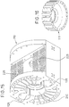
- the cylinders are preferably forced air-cooled but they can be also liquid cooled.
- a finned area is provided around the cylinders through which forced air flows from cooling fan. Specifically said finned area is provided in the intermediate space between the outermost portion of the cylinder body and the cylinder where the pistons are received. Forced air is flows through said intermediate portion coming from the cooling fan. Cooling is thus performed in a better-distributed and efficient way.
- Respective lubrication portions are defined between the opposite end portions of the engine block and the engine block itself.
- exhaust ports are opened by the piston head causing exhaust of gases due to pressure differential of the cylinder and the exhaust collector.
- opening of the exhaust ports is carried out in advance in order to ensure that when the intake ports are opening, pressure inside the cylinder has dropped sufficiently to allow fresh gases entering through the intake ports.
- exhaust gases are swept through the exhaust ports.
- exhaust ports are closed by the exhaust piston heads while the intake ports continue opened at a given angle, such that cylinder intake is optimized.
- the fuel is injected into the cylinder. Shortly before the TDC ignition starts again causing combustion.
- one of the power cams may have a through hole along its shaft and the other power cam may have its shaft extended such that it passes through the other power cam to its rear portion. Up to this point the two power cams are allowed to rotate freely with no link between them.
- the shifting means for rotating the two power cams to each other are received between the rear portion of the power cam with the through hole and the side crankcase. Said shifting means could also be provided outside the side crankcase.
- a further embodiment is also envisaged in which the helical ramps interacting with the shifter comprise helical teeth and a secondary shaft is provided parallel to the cam shaft.
- Said secondary shaft has two helical gears meshing with each of the teeth of the shafts. Therefore, this secondary shaft rotates together with the power cam shafts and causes them to be rotated together.
- said secondary shaft can be displaced linearly such that the relative angle between the power cams is varied.
- the power cams and the corresponding shafts are not formed integrally with each other and the power cams can be slightly rotated relative to the corresponding shaft.
- radially distributed chambers are defined inside the power cams .
- a wall is provided dividing the chamber into two areas. Said wall is formed integrally with the shaft and divides each chamber into two sub-chambers. In this way, when oil under pressure is suitably fed into each sub-chamber the power cams are caused to be rotated to the desired position.
- the cam tracks are shaped such that peaks and valleys are equal.
- the slider should start from a position (idling) to a position in which the exhaust cam track is rotated a suitable angle with respect to the intake cam track.
- the profile of the intake and exhaust cam tracks are similar to each other, and even equal, so that vibrations (especially at low speeds) are minimized since the exhaust and intake pistons move symmetrically. This results in that peak forces of the cylinders, piston body, power cams, etc., are greatly reduced, thus decreasing the wear, vibration, etc.
- the present engine is highly flexible in relation to design and calculation so it can be better configured for the use to which it is intended.
- the present internal combustion engine provides many advantages. Said advantages include, but are not limited to, the common advantages of the known opposed piston engines where side loads are eliminated or at least greatly reduced and with a very simple and therefore cost effective construction.
- the most significant advantage of the present internal combustion engine is that distribution and compression ratio can be dynamically and simultaneously varied as the engine is running. Such dynamic and simultaneous variation of engine distribution and compression ratio are achieved in a very simple way resulting in higher torque over a wide range of engine speeds, opening and closing of intake and exhaust ports being fitted at any time to engine requirements, an increased engine performance, reduced pollutants and an increased fuel efficiency while the engine is working under varying loads.
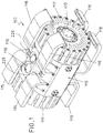
- a twin cylinder, three-stroke, opposed piston, direct injection petrol engine is shown in the figures by way of an example. It been indicated as a whole by reference numeral 100.
- the opposed piston engine 100 comprises a cylindrical engine block 110.
- the embodiment shown in figure 1 is one possible example of an engine block 110. However, it could be different in shape, such as prismatic or irregular, according to the specific requirements.
- holes 118, 119 are formed in the engine block 110 for cooling purposes.
- Intake collectors 116 and exhaust collectors 115 are provided on the engine block 110.
- the intake and exhaust collectors 116, 115 lead to corresponding exhaust and intake ports (not shown).
- Cylinders 120, 130 are arranged inside the engine block 110 separated 180o from each other in the axial direction of their corresponding longitudinal axes X, parallel to each other.
- the cylinders 120, 130 are formed integral with the engine block 110 although they could be separated parts coupled to the engine block 110.
- the cylinders 120, 130 may be arranged to work in any desired position, such as horizontal, vertical or inclined.
- the engine block 110 is further provided with side crankcases 117 located at its opposites ends as shown in figure 1 , surrounding cylinders 120, 130.
- the side crankcases 117 house power cams 300, 400, that will be explained further below, within the engine block 110.
- the side crankcases 117 absorb piston expansion forces and define lubrication areas.
- pistons 140, 150 and 160, 170 are provided within each cylinder 120, 130. Pistons 140, 150 and 160, 170 in their respective cylinder 120, 130 are aligned to each other such that in use, pistons 140, 150 and 160, 170 reciprocate along the longitudinal axis of the cylinder, that is, along their longitudinal axes X.
- Pistons 140, 150 and 160, 170 are associated with the above mentioned intake and exhaust ports.
- exhaust ports are driven by exhaust pistons and intake ports are driven by intake pistons. Opening and closing of intake and exhaust ports is controlled as set out below.
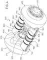
- each combustion chamber 250 is defined by the space between two adjacent pistons 140, 150 and 160, 170 in each cylinder 120, 130, as shown in figure 4 .
- Corresponding spark plugs are provided inside the combustion chamber 250 in each cylinder 120, 130.
- the spark plugs 230, 231 can be fitted through corresponding access holes 225, 226 formed in an upper housing and received inside the engine block 110, as shown in figures 1-3 of the drawings.
- the above mentioned intake and exhaust ports are formed in correspondence with said chambers 250.
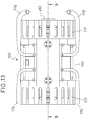
- FIGS 7-10 show one embodiment of the pistons 140, 150 and 160, 170.
- Pistons 140, 150 and 160, 170 each comprises a piston head 180, a piston body 190 and a connector 200.
- the connector 200 can be shown in the sectional view of figure 8 .
- the connector 200 is formed like a connecting rod for connecting the piston head 180 with the piston body 190 to each other with no or little oscillating movement.
- the connector 200 comprises three parallel rods 210 mutually joined by a bottom common shaft 220 and an upper common shaft 221 which connect the piston head 180 and the piston body 190.
- the piston head 180 carries compression and lubrication piston segments 185, 186 as shown in figures 7-10 .
- the compression piston segments 185 are arranged at one end of the pistons 140, 150 and 160, 170, near the combustion chamber 250.
- the lubrication piston segments 186 are arranged in the lowermost part of the piston head 180, close to the compression piston segments 185 taking into account that in the compression stroke ports can not be opened for preventing oil from entering ports and therefore the cylinder 120, 130.
- Each piston body 190 has an indentation 280 as shown in figure 10 .
- the indentation 280 is formed at one end of each piston 140, 150 and 160, 170 and it is suitable for preventing the piston body from hitting the corresponding cam track.
- the cylinders 120, 130 have an indentation 125, 135 formed in opposite ends for allowing the counter cam follower wheel 228 and its shaft do not collide with the cylinders 120, 130. This can be seen in figure 15 of the drawings.
- Pistons 140, 150 and 160, 170 are provided with locking means for preventing the pistons 140, 150 and 160, 170 from being rotated.
- the locking means as shown in figures 3 and 4 , comprise a groove 260 formed along the piston body 190 intended for receiving a projection 270 formed in the cylinder 120, 130.
- the projection 270 may be attached to the cylinder 120, 130 or it may be integral therewith.
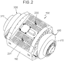
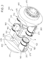
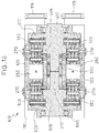
- the engine 100 shown in the figures further comprises two mutually opposed power cams 300, 400 as shown in figures 2 and 3 of the drawings and in greater detail, disassembled from the engine 100, in figures 11 and 12 .
- the power cams 300, 400 are rotatably fitted inside the engine block 110 at the opposite ends thereof, facing each other.
- each power cam has cam tracks 315, 316, 415, 416.
- the cam tracks 315, 316, 415, 416 are shaped such that each half turn of the first and second rotary shafts 500, 600 causes a complete combustion and completes the thermodynamic cycle.
- figures 11 and 12 illustrates intake cam tracks 315, 316 and exhaust cam tracks 415, 416 of the power cams 300, 400.
- Intake cam tracks 315, 316 are equal to one another.
- Exhaust cam tracks 415, 416 are equal to one another.
- Said cam tracks 315, 316, 415, 416 are defined by respective protruding areas or protrusions formed therein as shown in said figures 11 and 12 .
- the intake cams track control the movement of intake pistons, that is, pistons associated with the engine intake stroke while exhaust cam tracks control the movement of exhaust pistons, that is, pistons associated with the engine exhaust stroke depending upon the stroke in use.
- Opening and closing of the ports is thus controlled by the profile of each of the cam tracks 315, 316, 415, 416 in a way that the exhaust piston is advanced with respect to the intake piston. Therefore, before at the end of the power stroke, opening of the exhaust port is carried out before opening of the intake port and at the beginning of the compression exhaust port closes before closing the intake port.
- Respective output shafts 310, 410 are connected to the respective power cams 300, 400, as shown in figures 11 and 12 .
- the output shafts 310, 410 can be attached to the power cams 300, 400 or they can be integrally formed therewith.
- First and second rotary shafts 500, 600 are also provided inside the engine block 110, in a substantially central portion, as shown in figure 4 .
- the first and second rotary shafts 500, 600 are aligned to each other, with their free ends next to each other but not in contact with each other.
- the first and second rotary shafts 500, 600 are connected to or are formed integral with the respective power cams 300, 400, as shown in figures 11 and 12 .
- the pistons 140, 150 and 160, 170 have a respective drive end.
- the drive end in each of the pistons 140, 150 and 160, 170 comprises three cam follower wheels 227.
- the follower wheels 227 are adapted to roll onto the respective power cams 300, 400.
- the drive end in each of the pistons 140, 150 and 160, 170 further comprises the above mentioned counter cam follower wheel 228.
- Said counter cam follower wheel 228 is adapted to roll onto respective counter cams 305, 405 which will be described in greater detail according to figures 3 , 4 , 11, 12 and 15 of the drawings.
- each piston 140, 150 and 160, 170 are mounted on the above mentioned common shaft 220 as shown in figures 7, 8 and 10 .
- the common shaft 220 is arranged perpendicular to said first and second shafts 500, 600 and to the longitudinal axis X of the pistons 140, 150 and 160, 170.
- the follower wheels 227 roll on the respective first and second power cams 300, 400.
- Reciprocation of pistons 140, 150 and 160, 170 against the power cams 300, 400 results in that a rotating motion is imparted to the first and second rotary shafts 500, 600 to drive the engine 100, causing the output shafts 310, 410 to be rotated.
- FIG 3 the first and second rotary shafts 500, 600 of the engine 100 are linked to each other through an attachment device 700.
- the attachment device 700 that has been removed from the engine 100 in figure 4 for the sake of clarity in order to show the first and second rotary shafts 500, 600, is arranged inside the engine block 110.
- the attachment device 700 connects the first and second rotary shafts 500, 600 to each other so that they can be rotated together in operation.
- the attachment device 700 comprises shifting means 705.
- the shifting means 705 include a slider 710.
- the slider 710 comprises two main bodies 711, 712 attached to each other.
- the slider 710 is commanded by a control unit (not shown) causing it to be displaced along the longitudinal axis of the first and second rotary shafts 500, 600 through a motor means comprising a servomotor M.
- Other motor means controlled by the control unit (not shown) for displacing the slider 710 are not rule out, such as motor means comprising a hydraulic motor.
- the slider 710 includes an inner bushing 720 rotatably mounted therein through bearings 721.
- a number of helical teeth 730 are provided in an inner surface of bushing 720, shown in detail in figure 6 .
- the inner bushing helical teeth 730 are arranged to engage the respective helical teeth 505, 605 formed at the respective mutually adjacent or proximate ends of the first and second rotary shafts 500, 600 as shown in figures 4 , 11 and 12 .
- the driving assembly 715 comprises a driving arm 716 acting on a connecting rod 717.
- the connecting rod 717 of the driving assembly 715 connects the driving arm 716 with the main bodies 711, 712 of the slider 710 through a fork element 718 attached to them.
- the intake and exhaust power cams 300, 400 in this specific example are equal to each other. Therefore a suitable angular shift exists between the power cams 300, 400.
- the angular shift is of the order of 4,5o. This means that the exhaust power cam is advanced relative to the intake power cam. This is an initial angular shift between the power cams which is not caused by the attachment device 700 but is due to the design of the helical teeth 730, 505, 605 of the slider 720 and the first and second rotary shafts 500, 600.
- the slider 710 can travel a maximum displacement of the order of 16 mm and as a consequence the power cams 300, 400 are rotated to each other, that is, the exhaust power cam is advanced relative to the intake power cam, up to 12,8o in this specific example. This however may vary depending upon gear pitch, teeth shape (whether they are constant or variable radius teeth, etc).
- pistons 140, 150 and 160, 170 act, through their respective drive end, on the power cams 300, 400 causing them, together with the first and second rotary shafts 500, 600, to be rotated in the same direction while the slider 710 is actuated, that is, displaced along them, causing the engine distribution and compression ratio are changed.
- respective counter cams 305, 405 are provided in correspondence with each power cam 300, 400.
- the counter cams 305, 405 are received in respective recesses 240 formed at both ends of the engine block 110 as shown in figure 15 .
- the counter cams 305, 405 are attached to or are part of the respective first and second shafts rotary 500, 600.
- the counter cams 305, 405 are attached to or are part of the respective power cams 300, 400.
- the diameter of the counter cams 305, 405 is smaller than that of the power cams 300, 400.
- the counter cams 305, 405 have the same shape and they are facing each other.
- the counter cams 305, 405 are adapted to prevent pistons 140, 150 and 160, 170 from losing contact with the cam tracks 315, 316, 415, 416 of the power cams 300, 400 and thus to prevent possible collisions with each other which might occur when inertial forces of the pistons 140, 150 and 160, 170 are in opposite direction to those of the power cams 300, 400 and the gas pressure inside the cylinder or cylinders 120, 130 is lower than said inertial forces.
- shifting means 705 have been disclosed herein as comprising a slider 710 such that as it is moved along the longitudinal axis of the first and second rotary shafts 500, 600, said first and second rotary shafts 500, 600 are rotated to each other, other alternative mechanical embodiments are possible.
- the shifting means 705 might comprise a rotary actuator. As such actuator is rotated, the first and second rotary shafts 500, 600 are rotated to each other resulting in that the engine distribution and compression ratio are changed as stated above.
Landscapes
- Engineering & Computer Science (AREA)
- Mechanical Engineering (AREA)
- General Engineering & Computer Science (AREA)
- Chemical & Material Sciences (AREA)
- Combustion & Propulsion (AREA)
- Combustion Methods Of Internal-Combustion Engines (AREA)
- Output Control And Ontrol Of Special Type Engine (AREA)
- Valve Device For Special Equipments (AREA)
- Transmission Devices (AREA)
- Cylinder Crankcases Of Internal Combustion Engines (AREA)
Claims (14)
- Ein Verbrennungsmotor (100) umfassend mindestens einen Zylinder (120, 130), der versehen mit entsprechenden Kolben (140, 150, 160, 170) ist, die angeordnet sind, um sich entlang der Längsachse (X) jedes Zylinders (120, 130) hin und her zu bewegen, und mindestens einen ersten und zweiten Arbeitsnocken (300, 400), die gegenüber einander angeordnet sind und mit entsprechenden ersten und zweiten rotierenden Wellen (500, 600) verbunden sind, wobei die Hinundherbewegung der Kolben (140, 150, 160, 170) zur Folge hat, dass die Kolben (140, 150, 160, 170) auf den ersten und den zweiten Arbeitsnocken (300, 400) wirken, wodurch eine Drehbewegung der ersten und der zweiten rotierenden Welle (500, 600) zum Antrieb des Motors (100) hervorgerufen wird, wobei er weiterhin eine Verbindungsvorrichtung (700) zur Verbindung der ersten und der zweiten rotierenden Welle (500, 600) miteinander umfasst, so dass sie zusammen drehen können, wobei die Verbindungsvorrichtung (700) ein Schaltmittel (705) zum Schalten der relativen Winkelposition der ersten und der zweiten rotierenden Welle (500, 600) umfasst, wobei der Motor (100) Gegennocken (305, 405) umfasst, die mit jedem Arbeitsnocken (300, 400) verknüpft sind, um zu verhindern, dass der Kontakt der Kolben (140, 150, 160, 170) mit den Arbeitsnocken (300, 400) unterbrochen wird, wobei die Kolben (140, 150, 160, 170) mindestens ein mitlaufendes Gegenrad (228) umfassen, das angepasst ist, um auf einem Gennocken (305, 405) zu rollen und die Zylinder (120, 130) eine in gegenüber liegenden Enden davon gebildete Einkerbung (125, 135) haben, damit das mit dem Gegennocken verknüpfte Gegenrad (228) und seine Welle nicht mit den Zylindern (120, 130) zusammenstoßen.
- Der Motor (100) des Anspruchs 1, wobei das Schaltmittel (705) ein Gleitstück (710) umfasst, das Zähne (730) umfasst, die geeignet sind, um im Eingriff mit entsprechenden Zähnen (505, 605) der ersten und der zweiten drehbaren Welle (500, 600) zu kommen, so dass, wenn das Gleitstück (710) entlang der Längsachse der ersten und der zweiten drehbaren Welle (500, 600) geschoben wird, die erste und die zweite drehbare Welle (500, 600) bezüglich einander gedreht werden.
- Der Motor (100) des Anspruchs 2, wobei die Zähne (730, 505, 605) sowohl vom Gleitstück (710) als auch von der ersten und der zweiten drehbaren Welle (500, 600) spiralförmig sind, wobei die Zähne (505) der ersten drehbaren Welle (500) symmetrisch bezüglich der Zähne (605) der zweiten drehbaren Welle (600) sind.
- Der Motor (100) von einem der Ansprüche 2-3, wobei das Schaltmittel (705) ein Antriebsmittel zur Betätigung des Gleitstücks umfasst.
- Der Motor (100) von einem der vorhergehenden Ansprüche, wobei die Kolben (140, 150, 160, 170) mindestens ein zum Rollen auf einem Arbeitsnocken (300, 400) angepasstes mitlaufendes Rad (227) umfassen.
- Der Motor (100) von einem der vorhergehenden Ansprüche, wobei jeder Arbeitsnocken (300, 400) mit mindestens einer Nockenbahn (315, 415) versehen ist.
- Der Motor (100) des Anspruchs 6, wobei jede Nockenbahn (315, 415) durch zwei jeweilige herausragende Flächen definiert ist, die derart ausgelegt sind, dass Auslassöffnungen in einem Arbeitstakt vor der Öffnung der Eingangsöffnungen geöffnet werden und Ausgangsöffnungen im Verdichtungstakt vor dem Schließen der Eingangsöffnungen geschlossen werden.
- Der Motor (100) des Anspruchs 7, wobei die jeweiligen Nockenbahnen (315, 415) mindestens einen steigenden Teil oder Verdichtungsteil und einen absteigenden Teil oder Arbeitsteil umfassen.
- Der Motor (100) von einem der vorhergehenden Ansprüche, wobei Kolben (140, 150, 160, 170) einen Kolbenboden (180), einen Kolbenkörper (190) und ein Verbindungsstück (200) zur Verbindung des Kolbenbodens (180) mit dem Kolbenkörper (190) umfassen.
- Der Motor (100) des Anspruchs 9, wobei eine Brennkammer (250) innerhalb jedes Zylinders (120, 130) definiert ist, die durch den zwischen zwei angrenzenden Kolbenböden (180) in jedem Zylinder (120, 130) gegebenen Raum gebildet ist.
- Der Motor (100) von einem der Ansprüche 6-10, wobei der Kolbenboden (190) eine Einkerbung (280) hat, die in gegenüber liegenden Enden gebildet ist und die ein Zusammenstoßen des Kolbenbodens (190) mit der Nockenbahn (315; 415) während Verdichtungs- und Arbeitstakte verhindert.
- Der Motor (100) von einem der vorhergehenden Ansprüche, wobei er weiterhin ein Arretierungsmittel umfasst, um eine Drehung der Kolben (140, 150, 160, 170) bezüglich jedes Zylinders (120, 130) zu verhindern.
- Der Motor (100) von einem der Ansprüche 10-12, wobei der Kolbenboden (180) Verdichtungskolbenabschnitte (185) trägt, die an einem Ende des Kolbenbodens (180) in der Nähe der Brennkammer (250) angeordnet sind und Schmierkolbenabschnitte (186) trägt, die in einem sich am tiefsten Teil des Kolbenbodens (180) befindenden Teil angeordnet sind.
- Der Motor (100) von einem der vorhergehenden Ansprüche, wobei jeder Zylinder (120, 130) an einer Seite Eingangsöffnungen hat, die durch Kolben gesteuert werden, welche wiederum durch die in einem Arbeitsnocken (300) bereitgestellten entsprechenden Nockenbahnen (315, 415) gesteuert werden, und Auslassöffnungen hat, die durch Kolben gesteuert werden, welche wiederum durch die in dem gegenüber liegenden Arbeitsnocken (400) bereitgestellten entsprechenden Nockenbahnen (315, 345) gesteuert werden.
Applications Claiming Priority (1)
| Application Number | Priority Date | Filing Date | Title |
|---|---|---|---|
| PCT/EP2013/072921 WO2015062673A1 (en) | 2013-11-04 | 2013-11-04 | Internal combustion engine |
Publications (2)
| Publication Number | Publication Date |
|---|---|
| EP3066312A1 EP3066312A1 (de) | 2016-09-14 |
| EP3066312B1 true EP3066312B1 (de) | 2019-02-20 |
Family
ID=49517517
Family Applications (1)
| Application Number | Title | Priority Date | Filing Date |
|---|---|---|---|
| EP13785878.3A Active EP3066312B1 (de) | 2013-11-04 | 2013-11-04 | Verbrennungsmotor |
Country Status (7)
| Country | Link |
|---|---|
| US (1) | US10267225B2 (de) |
| EP (1) | EP3066312B1 (de) |
| JP (1) | JP6364689B2 (de) |
| KR (1) | KR102108605B1 (de) |
| CN (1) | CN105849383B (de) |
| ES (1) | ES2717890T3 (de) |
| WO (1) | WO2015062673A1 (de) |
Cited By (2)
| Publication number | Priority date | Publication date | Assignee | Title |
|---|---|---|---|---|
| EP4290063A1 (de) | 2022-06-09 | 2023-12-13 | Innengine S.L. | Axial-verbrennungsmotor |
| US12000332B2 (en) | 2022-12-14 | 2024-06-04 | Matthew Jackson | System and method for opposed piston barrel engine |
Families Citing this family (4)
| Publication number | Priority date | Publication date | Assignee | Title |
|---|---|---|---|---|
| GB2517763B (en) * | 2013-08-30 | 2017-12-27 | Newlenoir Ltd | Piston arrangement and internal combustion engine |
| US10650621B1 (en) | 2016-09-13 | 2020-05-12 | Iocurrents, Inc. | Interfacing with a vehicular controller area network |
| US10465516B1 (en) | 2018-11-07 | 2019-11-05 | Hts Llc | Opposed piston engine cam shape |
| CN110578663B (zh) * | 2019-07-31 | 2021-05-25 | 杭州盛维科技有限公司 | 一种轴向柱塞泵及往复传动机构 |
Family Cites Families (20)
| Publication number | Priority date | Publication date | Assignee | Title |
|---|---|---|---|---|
| US1817375A (en) * | 1929-05-02 | 1931-08-04 | Imblum Aeronautical Company | Internal combustion engine |
| US2431686A (en) * | 1943-07-21 | 1947-12-02 | Deschamps Fuel Injection Corp | Variable capacity pump |
| GB855553A (en) * | 1957-12-17 | 1960-12-07 | United Engines Ltd | Internal combustion engines of the swash or wobble plate type |
| US2957462A (en) * | 1957-12-17 | 1960-10-25 | Clark Charles William | Internal combustion engines of the swash or wobble plate type |
| JPS63230947A (ja) * | 1987-03-19 | 1988-09-27 | Kubota Ltd | エンジンのセラミツクスヘツド付金属ピストン |
| CA1325897C (en) | 1988-08-29 | 1994-01-11 | Brian Leslie Powell | Crankless reciprocating machine |
| GB8926818D0 (en) * | 1989-11-28 | 1990-01-17 | Ehrlich Josef | Drive/driven apparatus |
| US5507253A (en) * | 1993-08-27 | 1996-04-16 | Lowi, Jr.; Alvin | Adiabatic, two-stroke cycle engine having piston-phasing and compression ratio control system |
| US5551383A (en) | 1995-07-20 | 1996-09-03 | Novotny; Rudolph J. | Internal combustion engine utilizing pistons |
| US6125819A (en) * | 1995-08-08 | 2000-10-03 | Strieber; Louis Charles | Rotating piston engine with variable effective compression stroke |
| KR0138397Y1 (ko) * | 1995-12-11 | 1999-03-20 | 한승준 | 피스톤 핀 윤활구멍이 형성된 피스톤 |
| NO306422B1 (no) * | 1997-04-25 | 1999-11-01 | Leif Dag Henriksen | Anordning ved forbrenningsmotor med innvendig forbrenning |
| JPH11257090A (ja) * | 1998-03-11 | 1999-09-21 | Yonehara Giken Kk | エンジン |
| JPH11294258A (ja) * | 1998-04-14 | 1999-10-26 | Hino Motors Ltd | 内燃機関用ピストン及びその組立て方法 |
| JP4149621B2 (ja) * | 1999-09-03 | 2008-09-10 | 邦彦 奥平 | 対向ピストン式2サイクルユニフロー型機関 |
| WO2005008038A2 (en) | 2001-12-18 | 2005-01-27 | Novotny Rudolph J | Internal combustion engine using opposed pistons |
| JP2012524198A (ja) | 2009-04-16 | 2012-10-11 | パウエル,ダーレン | 同軸クランクレスエンジン |
| WO2012113949A1 (es) | 2011-02-25 | 2012-08-30 | Garrido Requena Juan | Motor de combustión interna de tres tiempos |
| CN102359416B (zh) * | 2011-11-12 | 2013-05-15 | 吴以怡 | 一种逆向对冲内燃机 |
| US20160195008A1 (en) * | 2015-01-01 | 2016-07-07 | Cesar Mercier | Two-stroke opposed piston Rotary internal combustion engine with no reactive torque |
-
2013
- 2013-11-04 US US15/030,356 patent/US10267225B2/en active Active
- 2013-11-04 EP EP13785878.3A patent/EP3066312B1/de active Active
- 2013-11-04 CN CN201380080570.XA patent/CN105849383B/zh active Active
- 2013-11-04 KR KR1020167014582A patent/KR102108605B1/ko active IP Right Grant
- 2013-11-04 JP JP2016524468A patent/JP6364689B2/ja active Active
- 2013-11-04 ES ES13785878T patent/ES2717890T3/es active Active
- 2013-11-04 WO PCT/EP2013/072921 patent/WO2015062673A1/en active Application Filing
Non-Patent Citations (1)
| Title |
|---|
| None * |
Cited By (3)
| Publication number | Priority date | Publication date | Assignee | Title |
|---|---|---|---|---|
| EP4290063A1 (de) | 2022-06-09 | 2023-12-13 | Innengine S.L. | Axial-verbrennungsmotor |
| WO2023237695A1 (en) | 2022-06-09 | 2023-12-14 | Innengine, S.L. | Axial internal combustion engine |
| US12000332B2 (en) | 2022-12-14 | 2024-06-04 | Matthew Jackson | System and method for opposed piston barrel engine |
Also Published As
| Publication number | Publication date |
|---|---|
| KR20160089385A (ko) | 2016-07-27 |
| WO2015062673A1 (en) | 2015-05-07 |
| KR102108605B1 (ko) | 2020-05-08 |
| US20160237890A1 (en) | 2016-08-18 |
| US10267225B2 (en) | 2019-04-23 |
| JP2016535193A (ja) | 2016-11-10 |
| EP3066312A1 (de) | 2016-09-14 |
| CN105849383B (zh) | 2019-06-25 |
| JP6364689B2 (ja) | 2018-08-01 |
| ES2717890T3 (es) | 2019-06-26 |
| CN105849383A (zh) | 2016-08-10 |
Similar Documents
| Publication | Publication Date | Title |
|---|---|---|
| CA2261596C (en) | Opposed piston combustion engine | |
| US8726856B2 (en) | Internal combustion engine | |
| EP3066312B1 (de) | Verbrennungsmotor | |
| US7987823B2 (en) | Hybrid piston/rotary engine | |
| US8967097B2 (en) | Variable stroke mechanism for internal combustion engine | |
| JP3143564B2 (ja) | カム式エンジン | |
| EP2893166A1 (de) | Variabler hubmechanismus für einen verbrennungsmotor | |
| CN101072934B (zh) | 旋转机械场组件 | |
| US6619244B1 (en) | Expansible chamber engine | |
| US20130276761A1 (en) | Variable-compression engine assembly | |
| US7040262B2 (en) | Expansible chamber engine with undulating flywheel | |
| NL2011947C2 (en) | Combustion engine comprising a cylinder. | |
| US10947847B2 (en) | Engine crank and connecting rod mechanism | |
| PL171033B1 (pl) | Gwiazdowy silnik spalinowy PL PL PL | |
| US7188598B2 (en) | Rotary mechanical field assembly | |
| US9239002B2 (en) | Orbiting planetary gearing system and internal combustion engine employing the same | |
| JPH03149319A (ja) | クランクレスエンジン機構 | |
| JP3172366B2 (ja) | カム式エンジン | |
| WO2000036288A2 (en) | Pairing of combustion chambers in engines | |
| JPH07109931A (ja) | 往復運動を回転運動に変換する装置および該装置を用いたレシプロエンジン | |
| EP2925966B1 (de) | Verbrennungsmotor mit einem umlaufenden planetengetriebesystem | |
| CA3186118A1 (en) | Reciprocating mechanism | |
| WO2005019620A1 (en) | Expansible chamber engine with undulating flywheel | |
| WO2014052455A2 (en) | Orbiting planetary gearing system and internal combustion engine employing the same |
Legal Events
| Date | Code | Title | Description |
|---|---|---|---|
| PUAI | Public reference made under article 153(3) epc to a published international application that has entered the european phase |
Free format text: ORIGINAL CODE: 0009012 |
|
| 17P | Request for examination filed |
Effective date: 20160606 |
|
| AK | Designated contracting states |
Kind code of ref document: A1 Designated state(s): AL AT BE BG CH CY CZ DE DK EE ES FI FR GB GR HR HU IE IS IT LI LT LU LV MC MK MT NL NO PL PT RO RS SE SI SK SM TR |
|
| AX | Request for extension of the european patent |
Extension state: BA ME |
|
| DAX | Request for extension of the european patent (deleted) | ||
| GRAP | Despatch of communication of intention to grant a patent |
Free format text: ORIGINAL CODE: EPIDOSNIGR1 |
|
| STAA | Information on the status of an ep patent application or granted ep patent |
Free format text: STATUS: GRANT OF PATENT IS INTENDED |
|
| INTG | Intention to grant announced |
Effective date: 20180509 |
|
| GRAJ | Information related to disapproval of communication of intention to grant by the applicant or resumption of examination proceedings by the epo deleted |
Free format text: ORIGINAL CODE: EPIDOSDIGR1 |
|
| STAA | Information on the status of an ep patent application or granted ep patent |
Free format text: STATUS: REQUEST FOR EXAMINATION WAS MADE |
|
| REG | Reference to a national code |
Ref country code: DE Ref legal event code: R079 Ref document number: 602013051031 Country of ref document: DE Free format text: PREVIOUS MAIN CLASS: F02B0025080000 Ipc: F01B0003040000 |
|
| GRAJ | Information related to disapproval of communication of intention to grant by the applicant or resumption of examination proceedings by the epo deleted |
Free format text: ORIGINAL CODE: EPIDOSDIGR1 |
|
| GRAP | Despatch of communication of intention to grant a patent |
Free format text: ORIGINAL CODE: EPIDOSNIGR1 |
|
| STAA | Information on the status of an ep patent application or granted ep patent |
Free format text: STATUS: GRANT OF PATENT IS INTENDED |
|
| INTC | Intention to grant announced (deleted) | ||
| INTC | Intention to grant announced (deleted) | ||
| RIC1 | Information provided on ipc code assigned before grant |
Ipc: F02B 75/32 20060101ALI20180927BHEP Ipc: F01B 3/10 20060101ALI20180927BHEP Ipc: F02B 75/02 20060101ALI20180927BHEP Ipc: F02B 75/28 20060101ALI20180927BHEP Ipc: F02B 25/08 20060101ALI20180927BHEP Ipc: F01B 3/04 20060101AFI20180927BHEP Ipc: F02D 15/00 20060101ALI20180927BHEP |
|
| INTG | Intention to grant announced |
Effective date: 20181011 |
|
| GRAS | Grant fee paid |
Free format text: ORIGINAL CODE: EPIDOSNIGR3 |
|
| GRAA | (expected) grant |
Free format text: ORIGINAL CODE: 0009210 |
|
| STAA | Information on the status of an ep patent application or granted ep patent |
Free format text: STATUS: THE PATENT HAS BEEN GRANTED |
|
| AK | Designated contracting states |
Kind code of ref document: B1 Designated state(s): AL AT BE BG CH CY CZ DE DK EE ES FI FR GB GR HR HU IE IS IT LI LT LU LV MC MK MT NL NO PL PT RO RS SE SI SK SM TR |
|
| REG | Reference to a national code |
Ref country code: GB Ref legal event code: FG4D |
|
| REG | Reference to a national code |
Ref country code: CH Ref legal event code: EP |
|
| REG | Reference to a national code |
Ref country code: DE Ref legal event code: R096 Ref document number: 602013051031 Country of ref document: DE |
|
| REG | Reference to a national code |
Ref country code: AT Ref legal event code: REF Ref document number: 1098436 Country of ref document: AT Kind code of ref document: T Effective date: 20190315 |
|
| REG | Reference to a national code |
Ref country code: IE Ref legal event code: FG4D |
|
| REG | Reference to a national code |
Ref country code: ES Ref legal event code: FG2A Ref document number: 2717890 Country of ref document: ES Kind code of ref document: T3 Effective date: 20190626 Ref country code: NL Ref legal event code: MP Effective date: 20190220 |
|
| REG | Reference to a national code |
Ref country code: LT Ref legal event code: MG4D |
|
| PG25 | Lapsed in a contracting state [announced via postgrant information from national office to epo] |
Ref country code: SE Free format text: LAPSE BECAUSE OF FAILURE TO SUBMIT A TRANSLATION OF THE DESCRIPTION OR TO PAY THE FEE WITHIN THE PRESCRIBED TIME-LIMIT Effective date: 20190220 Ref country code: NL Free format text: LAPSE BECAUSE OF FAILURE TO SUBMIT A TRANSLATION OF THE DESCRIPTION OR TO PAY THE FEE WITHIN THE PRESCRIBED TIME-LIMIT Effective date: 20190220 Ref country code: LT Free format text: LAPSE BECAUSE OF FAILURE TO SUBMIT A TRANSLATION OF THE DESCRIPTION OR TO PAY THE FEE WITHIN THE PRESCRIBED TIME-LIMIT Effective date: 20190220 Ref country code: PT Free format text: LAPSE BECAUSE OF FAILURE TO SUBMIT A TRANSLATION OF THE DESCRIPTION OR TO PAY THE FEE WITHIN THE PRESCRIBED TIME-LIMIT Effective date: 20190620 Ref country code: NO Free format text: LAPSE BECAUSE OF FAILURE TO SUBMIT A TRANSLATION OF THE DESCRIPTION OR TO PAY THE FEE WITHIN THE PRESCRIBED TIME-LIMIT Effective date: 20190520 Ref country code: FI Free format text: LAPSE BECAUSE OF FAILURE TO SUBMIT A TRANSLATION OF THE DESCRIPTION OR TO PAY THE FEE WITHIN THE PRESCRIBED TIME-LIMIT Effective date: 20190220 |
|
| PG25 | Lapsed in a contracting state [announced via postgrant information from national office to epo] |
Ref country code: IS Free format text: LAPSE BECAUSE OF FAILURE TO SUBMIT A TRANSLATION OF THE DESCRIPTION OR TO PAY THE FEE WITHIN THE PRESCRIBED TIME-LIMIT Effective date: 20190620 Ref country code: BG Free format text: LAPSE BECAUSE OF FAILURE TO SUBMIT A TRANSLATION OF THE DESCRIPTION OR TO PAY THE FEE WITHIN THE PRESCRIBED TIME-LIMIT Effective date: 20190520 Ref country code: RS Free format text: LAPSE BECAUSE OF FAILURE TO SUBMIT A TRANSLATION OF THE DESCRIPTION OR TO PAY THE FEE WITHIN THE PRESCRIBED TIME-LIMIT Effective date: 20190220 Ref country code: HR Free format text: LAPSE BECAUSE OF FAILURE TO SUBMIT A TRANSLATION OF THE DESCRIPTION OR TO PAY THE FEE WITHIN THE PRESCRIBED TIME-LIMIT Effective date: 20190220 Ref country code: GR Free format text: LAPSE BECAUSE OF FAILURE TO SUBMIT A TRANSLATION OF THE DESCRIPTION OR TO PAY THE FEE WITHIN THE PRESCRIBED TIME-LIMIT Effective date: 20190521 Ref country code: LV Free format text: LAPSE BECAUSE OF FAILURE TO SUBMIT A TRANSLATION OF THE DESCRIPTION OR TO PAY THE FEE WITHIN THE PRESCRIBED TIME-LIMIT Effective date: 20190220 |
|
| REG | Reference to a national code |
Ref country code: AT Ref legal event code: MK05 Ref document number: 1098436 Country of ref document: AT Kind code of ref document: T Effective date: 20190220 |
|
| PG25 | Lapsed in a contracting state [announced via postgrant information from national office to epo] |
Ref country code: CZ Free format text: LAPSE BECAUSE OF FAILURE TO SUBMIT A TRANSLATION OF THE DESCRIPTION OR TO PAY THE FEE WITHIN THE PRESCRIBED TIME-LIMIT Effective date: 20190220 Ref country code: SK Free format text: LAPSE BECAUSE OF FAILURE TO SUBMIT A TRANSLATION OF THE DESCRIPTION OR TO PAY THE FEE WITHIN THE PRESCRIBED TIME-LIMIT Effective date: 20190220 Ref country code: AL Free format text: LAPSE BECAUSE OF FAILURE TO SUBMIT A TRANSLATION OF THE DESCRIPTION OR TO PAY THE FEE WITHIN THE PRESCRIBED TIME-LIMIT Effective date: 20190220 Ref country code: DK Free format text: LAPSE BECAUSE OF FAILURE TO SUBMIT A TRANSLATION OF THE DESCRIPTION OR TO PAY THE FEE WITHIN THE PRESCRIBED TIME-LIMIT Effective date: 20190220 Ref country code: EE Free format text: LAPSE BECAUSE OF FAILURE TO SUBMIT A TRANSLATION OF THE DESCRIPTION OR TO PAY THE FEE WITHIN THE PRESCRIBED TIME-LIMIT Effective date: 20190220 Ref country code: RO Free format text: LAPSE BECAUSE OF FAILURE TO SUBMIT A TRANSLATION OF THE DESCRIPTION OR TO PAY THE FEE WITHIN THE PRESCRIBED TIME-LIMIT Effective date: 20190220 |
|
| REG | Reference to a national code |
Ref country code: DE Ref legal event code: R097 Ref document number: 602013051031 Country of ref document: DE |
|
| PG25 | Lapsed in a contracting state [announced via postgrant information from national office to epo] |
Ref country code: SM Free format text: LAPSE BECAUSE OF FAILURE TO SUBMIT A TRANSLATION OF THE DESCRIPTION OR TO PAY THE FEE WITHIN THE PRESCRIBED TIME-LIMIT Effective date: 20190220 Ref country code: PL Free format text: LAPSE BECAUSE OF FAILURE TO SUBMIT A TRANSLATION OF THE DESCRIPTION OR TO PAY THE FEE WITHIN THE PRESCRIBED TIME-LIMIT Effective date: 20190220 |
|
| PLBE | No opposition filed within time limit |
Free format text: ORIGINAL CODE: 0009261 |
|
| STAA | Information on the status of an ep patent application or granted ep patent |
Free format text: STATUS: NO OPPOSITION FILED WITHIN TIME LIMIT |
|
| PG25 | Lapsed in a contracting state [announced via postgrant information from national office to epo] |
Ref country code: AT Free format text: LAPSE BECAUSE OF FAILURE TO SUBMIT A TRANSLATION OF THE DESCRIPTION OR TO PAY THE FEE WITHIN THE PRESCRIBED TIME-LIMIT Effective date: 20190220 |
|
| 26N | No opposition filed |
Effective date: 20191121 |
|
| PG25 | Lapsed in a contracting state [announced via postgrant information from national office to epo] |
Ref country code: SI Free format text: LAPSE BECAUSE OF FAILURE TO SUBMIT A TRANSLATION OF THE DESCRIPTION OR TO PAY THE FEE WITHIN THE PRESCRIBED TIME-LIMIT Effective date: 20190220 |
|
| PG25 | Lapsed in a contracting state [announced via postgrant information from national office to epo] |
Ref country code: TR Free format text: LAPSE BECAUSE OF FAILURE TO SUBMIT A TRANSLATION OF THE DESCRIPTION OR TO PAY THE FEE WITHIN THE PRESCRIBED TIME-LIMIT Effective date: 20190220 |
|
| REG | Reference to a national code |
Ref country code: CH Ref legal event code: PL |
|
| PG25 | Lapsed in a contracting state [announced via postgrant information from national office to epo] |
Ref country code: LI Free format text: LAPSE BECAUSE OF NON-PAYMENT OF DUE FEES Effective date: 20191130 Ref country code: CH Free format text: LAPSE BECAUSE OF NON-PAYMENT OF DUE FEES Effective date: 20191130 Ref country code: LU Free format text: LAPSE BECAUSE OF NON-PAYMENT OF DUE FEES Effective date: 20191104 Ref country code: MC Free format text: LAPSE BECAUSE OF FAILURE TO SUBMIT A TRANSLATION OF THE DESCRIPTION OR TO PAY THE FEE WITHIN THE PRESCRIBED TIME-LIMIT Effective date: 20190220 |
|
| REG | Reference to a national code |
Ref country code: BE Ref legal event code: MM Effective date: 20191130 |
|
| PG25 | Lapsed in a contracting state [announced via postgrant information from national office to epo] |
Ref country code: IE Free format text: LAPSE BECAUSE OF NON-PAYMENT OF DUE FEES Effective date: 20191104 |
|
| PG25 | Lapsed in a contracting state [announced via postgrant information from national office to epo] |
Ref country code: BE Free format text: LAPSE BECAUSE OF NON-PAYMENT OF DUE FEES Effective date: 20191130 |
|
| PG25 | Lapsed in a contracting state [announced via postgrant information from national office to epo] |
Ref country code: CY Free format text: LAPSE BECAUSE OF FAILURE TO SUBMIT A TRANSLATION OF THE DESCRIPTION OR TO PAY THE FEE WITHIN THE PRESCRIBED TIME-LIMIT Effective date: 20190220 |
|
| PG25 | Lapsed in a contracting state [announced via postgrant information from national office to epo] |
Ref country code: HU Free format text: LAPSE BECAUSE OF FAILURE TO SUBMIT A TRANSLATION OF THE DESCRIPTION OR TO PAY THE FEE WITHIN THE PRESCRIBED TIME-LIMIT; INVALID AB INITIO Effective date: 20131104 Ref country code: MT Free format text: LAPSE BECAUSE OF FAILURE TO SUBMIT A TRANSLATION OF THE DESCRIPTION OR TO PAY THE FEE WITHIN THE PRESCRIBED TIME-LIMIT Effective date: 20190220 |
|
| PG25 | Lapsed in a contracting state [announced via postgrant information from national office to epo] |
Ref country code: MK Free format text: LAPSE BECAUSE OF FAILURE TO SUBMIT A TRANSLATION OF THE DESCRIPTION OR TO PAY THE FEE WITHIN THE PRESCRIBED TIME-LIMIT Effective date: 20190220 |
|
| P01 | Opt-out of the competence of the unified patent court (upc) registered |
Effective date: 20230513 |
|
| PGFP | Annual fee paid to national office [announced via postgrant information from national office to epo] |
Ref country code: GB Payment date: 20231127 Year of fee payment: 11 |
|
| PGFP | Annual fee paid to national office [announced via postgrant information from national office to epo] |
Ref country code: ES Payment date: 20231201 Year of fee payment: 11 |
|
| PGFP | Annual fee paid to national office [announced via postgrant information from national office to epo] |
Ref country code: IT Payment date: 20231122 Year of fee payment: 11 Ref country code: FR Payment date: 20231127 Year of fee payment: 11 Ref country code: DE Payment date: 20231129 Year of fee payment: 11 |