EP3065654B1 - Dispositifs pour faciliter des procédures de gastrectomie longitudinale - Google Patents
Dispositifs pour faciliter des procédures de gastrectomie longitudinale Download PDFInfo
- Publication number
- EP3065654B1 EP3065654B1 EP14860011.7A EP14860011A EP3065654B1 EP 3065654 B1 EP3065654 B1 EP 3065654B1 EP 14860011 A EP14860011 A EP 14860011A EP 3065654 B1 EP3065654 B1 EP 3065654B1
- Authority
- EP
- European Patent Office
- Prior art keywords
- tube
- stomach
- distal end
- gastrectomy
- elongated member
- Prior art date
- Legal status (The legal status is an assumption and is not a legal conclusion. Google has not performed a legal analysis and makes no representation as to the accuracy of the status listed.)
- Active
Links
Images


Classifications
-
- A—HUMAN NECESSITIES
- A61—MEDICAL OR VETERINARY SCIENCE; HYGIENE
- A61F—FILTERS IMPLANTABLE INTO BLOOD VESSELS; PROSTHESES; DEVICES PROVIDING PATENCY TO, OR PREVENTING COLLAPSING OF, TUBULAR STRUCTURES OF THE BODY, e.g. STENTS; ORTHOPAEDIC, NURSING OR CONTRACEPTIVE DEVICES; FOMENTATION; TREATMENT OR PROTECTION OF EYES OR EARS; BANDAGES, DRESSINGS OR ABSORBENT PADS; FIRST-AID KITS
- A61F5/00—Orthopaedic methods or devices for non-surgical treatment of bones or joints; Nursing devices; Anti-rape devices
- A61F5/0003—Apparatus for the treatment of obesity; Anti-eating devices
- A61F5/0013—Implantable devices or invasive measures
- A61F5/0076—Implantable devices or invasive measures preventing normal digestion, e.g. Bariatric or gastric sleeves
-
- A—HUMAN NECESSITIES
- A61—MEDICAL OR VETERINARY SCIENCE; HYGIENE
- A61B—DIAGNOSIS; SURGERY; IDENTIFICATION
- A61B17/00—Surgical instruments, devices or methods, e.g. tourniquets
- A61B17/02—Surgical instruments, devices or methods, e.g. tourniquets for holding wounds open; Tractors
- A61B17/0218—Surgical instruments, devices or methods, e.g. tourniquets for holding wounds open; Tractors for minimally invasive surgery
-
- A—HUMAN NECESSITIES
- A61—MEDICAL OR VETERINARY SCIENCE; HYGIENE
- A61B—DIAGNOSIS; SURGERY; IDENTIFICATION
- A61B17/00—Surgical instruments, devices or methods, e.g. tourniquets
- A61B17/22—Implements for squeezing-off ulcers or the like on the inside of inner organs of the body; Implements for scraping-out cavities of body organs, e.g. bones; Calculus removers; Calculus smashing apparatus; Apparatus for removing obstructions in blood vessels, not otherwise provided for
- A61B17/22031—Gripping instruments, e.g. forceps, for removing or smashing calculi
- A61B17/22032—Gripping instruments, e.g. forceps, for removing or smashing calculi having inflatable gripping elements
-
- A—HUMAN NECESSITIES
- A61—MEDICAL OR VETERINARY SCIENCE; HYGIENE
- A61B—DIAGNOSIS; SURGERY; IDENTIFICATION
- A61B90/00—Instruments, implements or accessories specially adapted for surgery or diagnosis and not covered by any of the groups A61B1/00 - A61B50/00, e.g. for luxation treatment or for protecting wound edges
- A61B90/30—Devices for illuminating a surgical field, the devices having an interrelation with other surgical devices or with a surgical procedure
-
- A—HUMAN NECESSITIES
- A61—MEDICAL OR VETERINARY SCIENCE; HYGIENE
- A61F—FILTERS IMPLANTABLE INTO BLOOD VESSELS; PROSTHESES; DEVICES PROVIDING PATENCY TO, OR PREVENTING COLLAPSING OF, TUBULAR STRUCTURES OF THE BODY, e.g. STENTS; ORTHOPAEDIC, NURSING OR CONTRACEPTIVE DEVICES; FOMENTATION; TREATMENT OR PROTECTION OF EYES OR EARS; BANDAGES, DRESSINGS OR ABSORBENT PADS; FIRST-AID KITS
- A61F5/00—Orthopaedic methods or devices for non-surgical treatment of bones or joints; Nursing devices; Anti-rape devices
- A61F5/0003—Apparatus for the treatment of obesity; Anti-eating devices
- A61F5/0013—Implantable devices or invasive measures
- A61F5/0083—Reducing the size of the stomach, e.g. gastroplasty
-
- A—HUMAN NECESSITIES
- A61—MEDICAL OR VETERINARY SCIENCE; HYGIENE
- A61B—DIAGNOSIS; SURGERY; IDENTIFICATION
- A61B1/00—Instruments for performing medical examinations of the interior of cavities or tubes of the body by visual or photographical inspection, e.g. endoscopes; Illuminating arrangements therefor
- A61B1/273—Instruments for performing medical examinations of the interior of cavities or tubes of the body by visual or photographical inspection, e.g. endoscopes; Illuminating arrangements therefor for the upper alimentary canal, e.g. oesophagoscopes, gastroscopes
- A61B1/2736—Gastroscopes
-
- A—HUMAN NECESSITIES
- A61—MEDICAL OR VETERINARY SCIENCE; HYGIENE
- A61B—DIAGNOSIS; SURGERY; IDENTIFICATION
- A61B17/00—Surgical instruments, devices or methods, e.g. tourniquets
- A61B2017/00831—Material properties
- A61B2017/00876—Material properties magnetic
-
- A—HUMAN NECESSITIES
- A61—MEDICAL OR VETERINARY SCIENCE; HYGIENE
- A61B—DIAGNOSIS; SURGERY; IDENTIFICATION
- A61B17/00—Surgical instruments, devices or methods, e.g. tourniquets
- A61B17/22—Implements for squeezing-off ulcers or the like on the inside of inner organs of the body; Implements for scraping-out cavities of body organs, e.g. bones; Calculus removers; Calculus smashing apparatus; Apparatus for removing obstructions in blood vessels, not otherwise provided for
- A61B2017/22051—Implements for squeezing-off ulcers or the like on the inside of inner organs of the body; Implements for scraping-out cavities of body organs, e.g. bones; Calculus removers; Calculus smashing apparatus; Apparatus for removing obstructions in blood vessels, not otherwise provided for with an inflatable part, e.g. balloon, for positioning, blocking, or immobilisation
- A61B2017/22061—Implements for squeezing-off ulcers or the like on the inside of inner organs of the body; Implements for scraping-out cavities of body organs, e.g. bones; Calculus removers; Calculus smashing apparatus; Apparatus for removing obstructions in blood vessels, not otherwise provided for with an inflatable part, e.g. balloon, for positioning, blocking, or immobilisation for spreading elements apart
-
- A—HUMAN NECESSITIES
- A61—MEDICAL OR VETERINARY SCIENCE; HYGIENE
- A61B—DIAGNOSIS; SURGERY; IDENTIFICATION
- A61B17/00—Surgical instruments, devices or methods, e.g. tourniquets
- A61B17/30—Surgical pincettes without pivotal connections
- A61B2017/306—Surgical pincettes without pivotal connections holding by means of suction
-
- A—HUMAN NECESSITIES
- A61—MEDICAL OR VETERINARY SCIENCE; HYGIENE
- A61B—DIAGNOSIS; SURGERY; IDENTIFICATION
- A61B90/00—Instruments, implements or accessories specially adapted for surgery or diagnosis and not covered by any of the groups A61B1/00 - A61B50/00, e.g. for luxation treatment or for protecting wound edges
- A61B90/30—Devices for illuminating a surgical field, the devices having an interrelation with other surgical devices or with a surgical procedure
- A61B2090/309—Devices for illuminating a surgical field, the devices having an interrelation with other surgical devices or with a surgical procedure using white LEDs
Definitions
- the present disclosure relates generally to bariatric surgery and, more particularly, to devices and methods that facilitate performing sleeve gastrectomy procedures.
- Obesity is reaching epidemic proportions in many regions of the world, particularly in the United States.
- various surgical procedures have been developed including, for example, gastric bypass, adjustable gastric banding, and sleeve gastrectomy.
- the goal in each of these procedures is to reduce the patient's stomach capacity to restrict the amount of food that the patient can eat.
- the reduced stomach capacity results in a feeling of fullness for the patient after ingesting a relatively smaller amount of food.
- the patient can achieve significant weight loss.
- Sleeve gastrectomy involves transecting the stomach, e.g., using a stapling device or other suitable device, to reduce the patient's stomach volume.
- Sleeve gastrectomy procedures are often aided by the use of a bougie, which serves as a guide or template for transecting the stomach to the appropriate configuration while inhibiting inadvertent transection of stomach or esophageal tissue.
- a bougie serves as a guide or template for transecting the stomach to the appropriate configuration while inhibiting inadvertent transection of stomach or esophageal tissue.
- EPC discloses a gastric tube for use in a bariatric surgical procedure comprising an elongate tube having a convex portion extending longitudinally along the tube with a concave depression defining a groove for slidable receipt of a sail member which is moveable between an unexpanded and expanded position.
- the sail member further includes a plurality of lights disposed thereon and along an entirety of its length.
- Gastrectomy devices for use in bariatric surgery are provided in accordance with the present disclosure.
- a gastrectomy device includes an elongated flexible tube member, a balloon member, and a shape modification member.
- a gastrectomy device includes a shaft having at least one expandable feature.
- a gastrectomy device includes at least one stapling location identifying feature.
- the present invention provides a gastrectomy device including an elongated member, a tube, and an array of lights.
- the elongated member has a proximal end and a distal end.
- the elongated member defines a longitudinal side window disposed adjacent the distal end, a first longitudinal channel having the tube extending therethrough, the tube having a proximal and a distal end, the first longitudinal channel being in communication with the longitudinal side window which is large enough to allow passage of a portion of the tube therethrough.
- the device further comprises a plurality of side apertures, and a second longitudinal channel fluidly isolated from the first longitudinal channel and being in communication with the plurality of side apertures.
- the second longitudinal channel is configured for coupling to a source of pressure.
- the tube extends through the first longitudinal channel and has a proximal end and a distal end.
- the array of lights is associated with the tube to provide illumination.
- the tube is movable through the elongated member between a first state, in which the tube is disposed within the first longitudinal channel contained within the elongated member, and a second state, in which a portion of the tube extends through the longitudinal side window outside of the elongated member.
- the gastrectomy device may further include an elongated printed circuit board disposed within the tube.
- the printed circuit board has the array of lights disposed thereon. It is contemplated that the array of lights may be LEDs.
- the gastrectomy device may further include a handle assembly coupled to the proximal end of the elongated member.
- the tube may be translatable through the handle assembly.
- the handle assembly may include a power source.
- the power source may be a battery.
- the battery may be electrically connected to the array of lights.
- the handle assembly may include an activation strip removably coupled to the handle assembly.
- the handle assembly may include a luer assembly in fluid communication with the second longitudinal channel of the elongated member.
- the luer assembly may be configured for connection to the source of pressure.
- the source of pressure may provide positive or negative pressure.
- the source of pressure may be a vacuum source or an insufflation source.
- the distal end of the elongated member may have a wireless receiver.
- the elongated member may be formed of a flexible material.
- the elongated member may form an arc in the second state.
- the tube may have an actuator fixed to the proximal end thereof.
- a method of performing bariatric surgery includes inserting the gastrectomy device into an oral cavity of a patient, guiding the gastrectomy device along an enteral pathway, repositioning the gastrectomy device based on an observed position of the illuminated tube to a selected position within a stomach of the patient, moving the tube from a first state to a second state, in which the tube bows outwardly through the longitudinal side window of the elongated member into engagement with a portion of the stomach, and transecting a portion of the stomach.
- guiding the gastrectomy device along the enteral pathway may include advancing the gastrectomy device from an oral cavity through an esophagus into an antrum of the stomach.
- the method may further include at least one of: insufflating fluid through the second longitudinal channel and out of the plurality of side apertures; or vacuuming fluid from the antrum of the stomach through the plurality of side apertures and into the second longitudinal channel.
- moving the tube may include sliding the proximal end of the tube distally relative to the elongated member through the first longitudinal channel.
- proximal will refer to the portion of the device or component thereof that is closest to the user and the term “distal” will refer to the portion of the device or component thereof that is farthest from the user.
- examples of sleeve gastrectomy devices are provided in accordance with the present disclosure for effectuating gastrectomy procedures involving shape modification and/or remodeling.
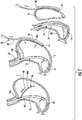
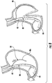
- FIG. 1 one example of a sleeve gastrectomy device is shown generally identified by reference numeral 10.
- Device 10 includes a tubular member 12 and an expandable balloon 14 supported on a distal end of tubular member 12.
- Tubular member 12 defines an aperture 12a through which a magnetic member 16 of device 10 can be advanced.
- Balloon 14 is selectively inflatable and deflatable, for example, in the antrum of the stomach "S" to position device 10 for effectuating a sleeve gastrectomy procedure.
- Magnetic member 16 includes a distal end portion 16a that supports one or more magnets 18 and/or magnetic material and a proximal end portion 16b.
- Magnetic member is advanced out of device 10 so that distal end portion 16a is positioned against an internal surface of stomach "S” for remodeling a curvature of stomach “S.”
- a manipulation tool 20 having a shaft 22 that supports a capturing portion 24 can be positioned on an external surface of stomach “S” adjacent to distal end portion 16a of magnetic member 16 to magnetically secure distal end portion 16a to stomach “S.”
- the stomach “S” can then be resected, as appropriate, separating the stomach “S” into a resected portion "R” and a new stomach portion “SN.”
- any number of open or laparoscopic stomach resection techniques/devices can be used including surgical staplers, vessel sealing devices, suturing and scalpels, etc.
- the new stomach portion "SN” is tested for extravasation using any suitable technique, for example, by insufflating with saline and/or a dye, etc.
- the resected portion "R” can then be removed with distal end portion 16a, which is severed at proximal end portion 16b during resection, upon withdrawing manipulation tool 20 and balloon 14 can be deflated so that device 10 can be withdrawn.
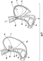
- Device 30 includes a tubular member 32 and an expandable balloon 34 supported on a distal end of tubular member 32.
- Tubular member 32 defines a first aperture 32a and a second aperture 32b.
- a form wire 36 is supported on tubular member 32 by suture 38.
- Form wire 36 includes a first wire anchor 36a on a distal end thereof and a second wire anchor 36b on a proximal end thereof.
- Suture 38 includes a first portion 38a and a second portion 38b, each of which may be separate sutures.
- first portion 38a extends through first aperture 32a and is secured to a distal end portion of form wire 36 and second portion 38b extends through second aperture 32b and is secured to a proximal end portion form wire 36.
- balloon 34 is selectively inflated in the antrum of stomach “S” to position device 30 for effectuating a sleeve gastrectomy procedure.
- Suture 38 is advanced out of device 30 so that form wire 36 separates from tubular member 32 and spring biases against an internal surface of stomach “S” so that wire anchors 36a and 36b secure form wire 36 to stomach “S” for remodeling a curvature of stomach "S.”
- the stomach "S” can then be resected, as appropriate, separating the stomach "S” into a resected portion "R” and a new stomach portion "SN.”
- the new stomach portion "SN” can be tested for extravasation as described above.
- the resected portion "R” can be grasped by a separate forceps "F” and removed with form wire 36, which is separated from tubular member 32 when the suture 38 is severed during resection, and balloon 34 can be deflated so that device 30 can be withdrawn.
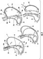
- Device 40 includes a tubular member 42 and an expandable balloon 44 supported on a distal end of tubular member 42.
- Tubular member 42 defines an aperture 42a.
- a rigid forming member 46 is advanceable through tubular member 42 and out of aperture 42a and has a suture 48 secured to a proximal end portion thereof.
- Rigid forming member 46 includes a first anchor 46a on a distal end thereof and a second anchor 46b on a proximal end thereof.
- balloon 44 is selectively inflated in the antrum of stomach "S” to position device 40 for effectuating a sleeve gastrectomy procedure.
- Rigid forming member 46 is advanced out of device 40 until suture 48 extends through aperture 42a so that first anchor 46a of rigid forming member 46 can be positioned against an internal surface of stomach "S.”
- a separate forceps "F” can then grasp rigid forming member 46 from an external surface of stomach “S” to support rigid forming member 46 against stomach “S.”
- rigid forming member 46 can be positioned flush against the internal surface of stomach “S” so that anchors 46a, 46b and forceps "F,” which is positioned centrally on rigid forming member 46, secure rigid forming member 46 to stomach “S” for remodeling a curvature of stomach “S.”
- Stomach "S” can then be resected, as appropriate, separating the stomach "S” into a resected portion "R” and a new stomach portion “SN.”
- the new stomach portion "SN”
- the resected portion "R” and rigid forming member 46 which is separated from tubular member 42 when suture 48 is severed during resection, can be removed by forceps "F," and balloon 44 can be deflated so that device 40 can be withdrawn.
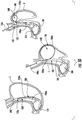
- Device 50 includes a tubular member 52 and a first expandable balloon 54 supported on a distal end of tubular member 52 and a second expandable balloon 56 supported on tubular member 52 proximally of first expandable balloon 54.
- the second balloon 56 can have a non-compliant shape.
- a distal end portion of second balloon 56 can be temporarily secured to tubular member 52 via suture 58.
- balloon 54 is selectively inflated in the antrum of stomach “S” to position device 50 for effectuating a sleeve gastrectomy procedure.
- Second balloon 56 is inflated against an internal surface of stomach “S” for remodeling a curvature of stomach “S.”
- the stomach "S” can then be at least partially resected, as appropriate, separating the stomach "S” into a resected portion "R” and a new stomach portion "SN.”
- first and second balloons 54, 56 can be deflated and device 50 can be withdrawn so that resection can be completed.
- the new stomach portion "SN” can be tested for extravasation as described above.
- the resected portion "R” can be grasped by a separate forceps "F” and removed.
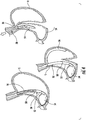
- FIG. 5 still another example of a sleeve gastrectomy device is shown generally identified by reference numeral 60.
- Device 60 includes a tubular member 62 and an expandable balloon 64 supported on a distal end of tubular member 62.
- Tubular member 62 defines an aperture 62a, out of which, an articulating member 66 can be advanced.
- Articulating member 66 includes a distal end portion 66a, a pivot portion 66b, a proximal end portion 66c, and an articulation pull wire 66d that is secured to distal end portion 66a.
- balloon 64 is selectively inflated in the antrum of stomach "S” to position device 60 for effectuating a sleeve gastrectomy procedure.
- Distal end portion 66a is advanced out of device 60 so that a proximally pulling of pull wire 66d pivots distal end portion 66a relative to proximal end portion 66c about pivot portion 66b to position distal end portion 66a against an internal surface of stomach "S” for remodeling a curvature of stomach "S.”
- the stomach "S” can then be at least partially resected, as appropriate, separating the stomach "S” into a resected portion "R” and a new stomach portion "SN.”
- articulation member 66 can be withdrawn so that resection can be completed.
- the new stomach portion "SN" can be tested for extravasation as described above.
- the resected portion "R” can be grasped by a separate forceps "F” and removed, and balloon 64 can be deflated so that device 60 can be withdrawn.
- Device 70 includes a tubular member 72 and an expandable balloon 74 supported on a distal end of tubular member 72.
- Tubular member 72 defines an aperture 72a, out of which, an articulating spine 76 can be advanced.
- Articulating spine 76 includes a distal end portion 76a and a plurality of vertebral members 76b.
- Each vertebral member of the plurality of vertebral members 76b defines a pull wire lumen 76c dimensioned to receive a pull wire 76d therethrough.
- the pull wire 76d is secured to distal end portion 76a, extends through each pull wire lumen 76c, and couples the plurality of vertebral members 76b together with distal end portion 76a.
- balloon 74 is selectively inflated in the antrum of stomach "S" to position device 70 for effectuating a sleeve gastrectomy procedure.
- Distal end portion 76a and at least some of the plurality of vertebral members 76b are advanced out of device 70 so that a proximal pulling of pull wire 76d articulates articulating spine 76 to that at least some of the plurality of vertebral members 76b abut against an internal surface of stomach "S” for remodeling a curvature of stomach "S,” which can be a predetermined curvature.
- the stomach "S” can then be at least partially resected, as appropriate, separating the stomach “S” into a resected portion "R” and a new stomach portion "SN.”
- articulation spine 76 can be withdrawn so that resection can be completed.
- the new stomach portion "SN” can be tested for extravasation as described above.
- the resected portion "R” can be grasped by a separate forceps and removed, and balloon 74 can be deflated so that device 70 can be withdrawn.
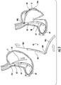
- Device 80 includes a tubular member 82 and an expandable balloon 84 supported on a distal end of tubular member 82.
- Tubular member 82 defines an aperture 82a, out of which, a flexible wire form 86 can be advanced.
- balloon 84 is selectively inflated in the antrum of stomach "S” to position device 80 for effectuating a sleeve gastrectomy procedure.
- Flexible wire form 86 is advanced out of device 80 and into an internal surface of stomach "S.”
- the flexibility of flexible wire form 86 enables flexible wire form 86 to curve into any suitable shape for remodeling a curvature of stomach "S.”
- flexible wire form 86 can be advanced against stomach "S” and curled to form a B-shape with a first looped portion 86a and a second looped portion 86b that cooperate to remodel the curvature of stomach "S" for resection.
- Stomach "S” can then be at least partially resected, as appropriate, separating the stomach "S” into a resected portion "R” and a new stomach portion "SN.”
- flexible wire form 86 can be withdrawn so that resection can be completed.
- the new stomach portion "SN” can be tested for extravasation as described above.
- the resected portion "R” can be grasped by a separate forceps and removed, and balloon 84 can be deflated so that device 80 can be withdrawn.
- device 80 can include a rigid wire form 88 instead of flexible wire form 86.
- Rigid wire form 88 includes a curved distal end portion 88a that is advanced out of device 80 and against stomach "S" to remodel a curvature of stomach "S.” Similar to that described above, stomach "S” can then be at least partially resected, as appropriate, separating the stomach "S” into a resected portion "R” and a new stomach portion "SN.”
- rigid wire form 88 can be withdrawn so that resection can be completed.
- the new stomach portion "SN” can be tested for extravasation as described above.
- the resected portion "R” can be grasped by a separate forceps and removed, and balloon 84 can be deflated so that device 80 can be withdrawn.
- Device 90 includes a tubular member 92 and an expandable balloon 94 supported on a distal end of tubular member 92.
- Tubular member 92 includes a distal end portion 92a and a proximal end portion 92b supported on distal end portion 92a.
- Proximal end portion 92b is positioned around distal end portion 92a to define a passage 92c therebetween that is dimensioned to receive a wire-forming loop 96.
- balloon 94 is selectively inflated in the antrum of stomach "S” to position device 90 for effectuating a sleeve gastrectomy procedure.
- Wire forming loop 96 is advanced out of passage 92c and into an internal surface of stomach "S.”
- Wire forming loop 96 defines a loop 96a that increases in diameter as wire-forming loop 96 is distally advanced from passage 92c and into contact with an internal surface of stomach "S” for remodeling the curvature of stomach "S” for resection.
- Stomach "S” can then be resected, as appropriate, while retracting wire-forming loop 96 to decrease the diameter of loop 96a as resection (e.g., stapling and cutting) progresses.
- the decrease in diameter of loop 96a may be indexed, for example, to correlate with the staple line formed in the stomach "S" during resection.
- the resection separates the stomach "S” into a resected portion "R” and a new stomach portion "SN.”
- Wire forming loop 96 can be withdrawn so that resection can be completed.
- the new stomach portion "SN” can be tested for extravasation as described above.
- the resected portion "R” can be grasped by a separate forceps and removed, and balloon 94 can be deflated so that device 90 can be withdrawn.
- Device 100 includes a tubular member 102 and an expandable balloon 104 supported on a distal end of tubular member 102.
- Tubular member 102 defines an attachment point 102a and supports a loop collar 106 dimensioned to linearly translate about an outer surface of tubular member 102.
- Loop collar 106 includes a collar 106a, wire member 106b, and an actuation rod 106c.
- Wire member 106b extends along an outer surface of tubular member 102 and is secured to attachment point 102a at a proximal end of wire member 106b and to collar 106a at a distal end of wire member 106b.
- a distal end of actuation rod 106c is secured to collar 106a to move collar 106 linearly relative to tubular member 102 upon linear translation of actuation rod 106c.
- Actuation rod 106c extends along tubular member 102 and can be arranged to extend along the outer surface of tubular member 102 and/or through tubular member 102.
- Tubular member 102 can define a channel (not shown) therealong to facilitate linear movement of collar 106a.
- balloon 104 is selectively inflated in the antrum of stomach "S" to position device 100 for effectuating a sleeve gastrectomy procedure.
- Actuation rod 106c is pulled proximally to draw collar 106a proximally.
- wire member 106b extends outwardly forming a loop 108 that engages an internal surface of stomach "S” to remodel the curvature of stomach “S” for resection. Similar to that described above, stomach "S” can then be at least partially resected, as appropriate.
- actuation rod 106c can be distally advanced to distally advance collar 106a and tighten slack formed in wire member 106b as loop 108 decreases in diameter.
- collar 106a is advanced to a distal most position, e.g., the insertion position, so that wire 106b is flush or substantially flush against tubular member 102 so that loop 108 can be retracted for final stapling and cutting.
- the stomach "S" is resected into a resected portion "R” and a new stomach portion "SN” that can be tested for extravasation as described above.
- the resected portion "R” can be grasped by a separate forceps and removed, and balloon 104 can be deflated so that device 100 can be withdrawn.
- System 110 includes a device 120 and grasping instrument 130.
- Device 120 includes a tubular member 122 and an expandable balloon 124 supported on a distal end of tubular member 122.
- Grasping instrument 130 includes an elongate body 132 and an end effector 134
- balloon 124 is selectively inflated in the antrum of stomach "S” to position device 120 for effectuating a sleeve gastrectomy procedure.
- End effector 134 of grasping instrument 130 can be used to grasp a portion of stomach “S” to be removed upon resection. Similar to that described above, stomach “S” can then be resected into a resected portion "R” and a new stomach portion "SN.” Upon completion of the resection, the new stomach portion "SN" can be tested for extravasation as described above.
- the resected portion "R” can be removed by grasping instrument 130, and balloon 104 can be deflated so that device 120 can be withdrawn.
- tubular members of sleeve gastrectomy devices can include at least one expandable feature to facilitate securement of the respective embodiments of gastrectomy devices within the stomach, for example, within the antrum of the stomach.
- Tubular member 140 includes an outer member 140a and an inner member 140b that defines a centerline "C.”
- Outer member 140a includes a plurality of umbrella members 142 that are selectively expandable relative to centerline "C" between a contracted state and an expanded state in response to linear movement of outer member 140a relative to inner member 140b, as indicated by arrow "a.”
- Each umbrella member 142 can have the same and/or different outer diameters in the contracted and/or expanded states and each umbrella member 142 includes a plurality of segments 142a that are positioned radially around tubular member 140.
- Each segment 142a of the plurality of segments 142a is spaced apart from the other segments 142a of the plurality of segments when umbrella member 142 is disposed in the expanded state and can be in contact with adjacent segments 142a when umbrella member 142 is in the contracted state.
- Tubular member 140 can be secured to vacuum source "VS" adapted to enable suction through one or more of the plurality of umbrella members 142 when in the expanded state.
- Tubular member 150 includes a shaft 152 and a polymer braid 154 with a plurality of braided filaments 154a secured to shaft 152.
- Shaft 152 defines a centerline "C.”
- Braid 154 is selectively expandable relative to centerline "C” between a contracted state and an expanded state in response to linear movement of braid 154 relative to shaft 152, as indicated by arrow "a.”
- Tubular member 150 can be secured to vacuum source "VS" adapted to enable suction between adjacent braided filaments 154a of braid 154 when braid 154 is in the expanded state.
- Tubular member 160 includes a shaft 162 that defines a centerline "C," a compliant balloon 164 supported on shaft 162, and a plurality of vacuum tubes 166 supported on balloon 164 and extending along shaft 162.
- Compliant balloon 164 can be coupled to an inflation source "IS" that is adapted to deliver inflation fluid, e.g., saline, to balloon 164 for selectively expanding and/or contracting balloon 164 between a contracted state and an expanded state relative to centerline "C.”
- the plurality of vacuum tubes 166 defines a plurality of vacuum ports 166a.
- a vacuum source "VS” can be coupled to vacuum tubes 166 to provide suction through vacuum ports 166a.
- Tubular member 170 includes a shaft 172 and a compliant balloon 174 supported on a side surface of shaft 172.
- Shaft 172 defines a centerline "C," a plurality of vacuum ports 172a, and vacuum lumen 172b that extends along centerline "C" and is in fluid communication with the plurality of vacuum ports 172a.
- a vacuum source "VS” can be coupled to vacuum lumen 172b to provide suction through vacuum ports 172a.
- Compliant balloon 174 is coupled to an inflation conduit 176 that extends along shaft 172 and can be coupled to an inflation source "IS" adapted to deliver inflation fluid, e.g., saline, to balloon 174 for selectively expanding and/or contracting balloon 174 between a contracted state and an expanded state relative to the side surface of shaft 172.
- IS inflation source
- Tubular member 180 includes a shaft 182 and a plurality of compliant balloons 184 supported in spaced-apart relation radially around an outer surface of shaft 182.
- Shaft 182 defines a centerline "C" and a plurality of vacuum ports 186 positioned between adjacent balloons 184 of the plurality of compliant balloons 184.
- the plurality of vacuum ports 186 includes a first port 186a, a second port 186b, and a third port 186c.
- Vacuum ports 186 are in fluid communication with a vacuum lumen 186d defined by shaft 182.
- Vacuum lumen 186d extends along centerline "C" of shaft 182.
- a vacuum source “VS” can be coupled to vacuum lumen 186d to provide suction through the plurality of vacuum ports 186.
- the plurality of compliant balloons 184 includes a first balloon 184a, a second balloon 184b, and a third balloon 184c.
- Each of the plurality of compliant balloons 184 is coupled to an inflation conduit 188 that extends along shaft 182 and can be coupled to an inflation source "IS" adapted to deliver inflation fluid, e.g., saline, to the balloons 184 for selectively expanding and/or contracting balloons 184 between a contracted state and an expanded state relative to the outer surface of shaft 182.
- a separate inflation conduit 188 can be coupled to each of first, second, and third balloons 184a, 184b, 184c.
- Tubular member 190 includes a shaft 192 and an expandable coil 194 helically supported around an outer surface of shaft 192.
- a distal end of expandable coil 194 is secured to a distal end portion of shaft 192 Shaft 192 defines a centerline "C,” and a plurality of vacuum ports 192a, and vacuum lumen 192b that extends along centerline "C" and is in fluid communication with the plurality of vacuum ports 192a.
- a vacuum source “VS” can be coupled to vacuum lumen 192b to provide suction through vacuum ports 192a.
- expandable coil 194 can be linearly advanced along shaft 192 relative to centerline “C” for selectively expanding and/or contracting coil 194 between a contracted state, where coil 194 is adjacent to shaft 192, and an expanded state, where coil 194 is spaced from shaft 192. Adjacent turns of expandable coil 194 are closer to one another in the expanded state than in the contracted state, and vice versa.
- Tubular member 200 includes an outer shaft 202a, an inner shaft 202b, and a rolling member 204 secured to a side surface of inner shaft 202b along an edge of rolling member 204.
- Inner shaft 202b defines a centerline "C" and a plurality of vacuum ports 206.
- rolling member 204 In response to rotational movement of inner shaft 202b, for example, in the direction indicated by arrow "bi," rolling member 204 is movable between a contracted state, where rolling member 204 is wrapped around inner shaft 202b in an overlapping arrangement in close proximity to the centerline “C,” and an expanded state, where rolling member 204 is unraveled, for example in the direction indicated by arrow “b 2 ,” so that portions of rolling member 204 are farther from centerline "C" than those respective portions are in the contracted state.
- a vacuum source “VS” can be coupled to vacuum ports 206, for example, via a vacuum lumen (not shown) to provide suction through vacuum ports 206.
- tubular member 210 can include a plurality of spaced apart rolling members such as rolling members 204a-204d, etc.
- Tubular member 220 includes a shaft 222 and a plurality of spaced-apart balloons 224 that are selectively expandable relative to a centerline "C" defined by shaft 222 between contracted and expanded states.
- the plurality of balloons 224 can includes a first balloon 224a, a second balloon 224b, and a third balloon 224c, etc., each of which can be coupled to one or more inflation conduits (not shown) defined by shaft 222 that are in fluid communication with an inflation source "IS.” Similar to that described above, shaft 222 defines a plurality of vacuum ports 222a in fluid communication with a vacuum source "VS,” for example, via a vacuum lumen (not shown) defined by shaft 222 that couples to vacuum source "VS.”
- Tubular member 230 includes a shaft 232 that supports a self-expanding member 234 and a linearly translatable sheath 236 supported on self-expanding member 234.
- Sheath 236 is retractable in the direction indicated by arrow "a" to free self-expanding member 234 to enable self-expanding member 234 to expand from a contracted state, where sheath 236 covers self-expanding member 234, to an expanded state, where sheath 236 is retracted.
- Self-expanding member 234 can be formed of a shape memory material such as nitinol and/or an electroactive polymer.
- Tubular member 240 includes a shaft 242 that defines a centerline "C" and supports an actuating assembly 244 and a blade assembly 246.
- Actuating assembly includes drive shaft 244a that supports an actuator face 244b on a distal end of drive shaft 244a.
- Actuator face 244b defines a plurality of channels 244c and a plurality of passages 244d.
- Blade assembly 246 includes a plurality of blades 246a and defines vacuum ports 246c between each blade 246a of the plurality of blades 246a.
- Each blade 246a of the plurality of blades 246a includes a finger 246b extending proximally from a proximal end portion of blade 246a.
- Each finger 246b is received within one of the plurality of channels 244c so that rotational movement of actuation assembly 244, for example, in the direction indicated by arrow "b," rotates actuator face 244b so that fingers 246b of each blade 246a slide through channels 244c to rotate blade assembly 246 between expanded and contracted states relative to centerline "C.”
- Vacuum ports 246c are in fluid communication with passages 244d, which can be coupled to a vacuum source "VS,” as described above.
- Tubular member 250 includes an outer shaft 252, an inner shaft 254 supported within outer shaft 252, and a clover member 256 supported on outer shaft 252.
- Inner shaft 254 defines a centerline "C.”
- Clover member 256 includes a plurality of radially spaced-apart clovers 256a and defines a central lumen 256b.
- Inner shaft 254 is linearly translatable relative to outer shaft 252, as indicated by arrow "a,” into central lumen 256b of clover member 256 so that the plurality of clovers 256a expands radially outwardly relative to the centerline "C" from a contracted state to an expanded state.
- Clover member 256 defines a plurality of vacuum ports 258 between the plurality of clovers 256a. Similar to that described above, vacuum ports 258 are in fluid communication with a vacuum source "VS" coupled to tubular member 250 at a proximal end portion thereof.
- VS vacuum source
- Tubular member 260 includes an inner shaft 262 that defines a centerline "C” and supports a plurality of stacked outer shafts 264 that are linearly translatable along centerline "C," as indicated by arrow "a" in a telescoping arrangement.
- the plurality of stacked outer shafts 264 can include a first outer shaft 264a, a second outer shaft 264b, and a third outer shaft 264c, etc., where each outer shaft has a different outer diameter with each successive outer diameter increasing in size so that tubular member 260 can expand from a contracted state, which can be defined by the diameter of the outer surface of inner shaft 262, to an expanded state, which can be defined the diameter of the outer surface of one of the plurality of stacked outer shafts 264.
- Any of the inner and/or outer shafts 262, 264 can define a plurality of vacuum ports 266 that can be disposed in fluid communication with a vacuum source "VS" as described above.
- Tubular member 270 includes a shaft 272 that defines a centerline "C,” a balloon member 274 supported on shaft 272 in fluid communication with an inflation source "IS,” and a foam member 276 supported on balloon member 274 that expands from a contracted state to an expanded state in response to inflation of balloon member 274 via inflation source "IS.”
- Foam member 276 is in fluid communication with one or more vacuum conduits 278 that are coupled to a vacuum source "VS" similar to that described above.
- Tubular member 280 includes an outer shaft 282 that defines a central lumen 282a and a centerline "C" and includes a low durometer distal portion 282b.
- Tubular member 280 supports a plurality of rods 284 that can be linearly advanced along centerline "C," as indicated by arrow "a,” into a distal end portion of central lumen 282a to expand distal portion 282b of outer shaft 282 from a contracted state to an expanded state.
- Outer shaft 282 can define a plurality of vacuum ports 286 that are in fluid communication with a vacuum source "VS" as described above.
- Tubular member 290 includes a shaft 292 that defines a centerline "C,” a plurality of expandable members 294, a plurality of rigid collars 296 interleaved between the plurality of expandable members 294, and an actuation rod 298 secured to a distal tip 292a of shaft 292.
- Actuation rod 298 is linearly translatable relative to centerline "C,” as indicated by arrow “a” to compress expandable members 294 against rigid collars 296 thereby expanding expandable members 294 from a contracted state to an expanded state.
- Collars 296 can define vacuum ports 296a that are in fluid communication with a vacuum source "VS,” similar to that described above.
- Tubular member 300 includes a shaft 302 that defines a centerline "C” and vacuum lumen 302a in fluid communication with a vacuum source "VS" as described above.
- Shaft 302 supports a plurality of inner shafts 304, each of the plurality of inner shafts 304 includes a curved portion 304a.
- Each inner shaft 304 of the plurality of inner shafts 304 is rotatable, as indicated by arrows "b," so that curved portions 304a rotate between a contracted state, where curved portions 304a are inwardly directed, to an expanded state, where curved portions 304a are outwardly directed.
- Tubular member 310 includes an outer shaft 312a that defines a centerline "C” and an inner shaft 312b that supports a clamshell assembly 314.
- One or both of inner and outer shafts 312a, 312b can define one or move vacuum ports (not shown) that are in fluid communication with a vacuum source "VS" similar to that described above.
- Clam shell assembly 314 includes a first shell 314a and second shell 314b that are pivotally coupled to an actuation rod 316 at pivot 314c so that a rotational movement of actuation rod 316, as indicated by arrow "b," moves clam shell assembly 314 between a contracted state, where first and second shells 314a, 314b are in close approximation with centerline “C,” and an expanded state, where first and second shells 314a, 314b are spaced from centerline "C.”
- Tubular member 320 includes a shaft 322 that defines a centerline "C," a plurality of laser cut tubes 324 disposed on shaft 322, and a sheath 326 secured to the plurality of laser cut tubes 324 that is linearly movable relative to the plurality of laser cut tubes 324, as indicated by arrow "a.”
- Sheath 326 can define a plurality of vacuum ports 328 that are in fluid communication with a vacuum source "VS" similar to that described above.
- Each tube of the plurality of laser cut tubes 324 includes a plurality of tines 324a disposed radially about the tube 324.
- Each tine of the plurality of tines 324a is secured to sheath 326 so that linear movement of sheath 326 moves tines 324a between a contracted state, where tines 324a and sheath 326 are in close proximity to centerline "C" and an expanded state, where tines 324a and sheath 326 are radially spaced from centerline "C.”
- Tubular member 330 includes a shaft 332 has an expandable portion 332a and defines a centerline "C," a central lumen 332b, and a plurality of vacuum ports 332c.
- Shaft 332 supports a mandrel 334 that is linearly movable through central lumen 332b, as indicated by arrow "a,” to move expandable portion 332a between a contracted state and an expanded state, as indicated by arrows "b.”
- Mandrel 334 defines a plurality of flutes 334a that extend along a length of mandrel 334 to provide a fluid communication between vacuum ports 332c and a vacuum source "VS" coupled to a proximal end portion of tubular member 330, as described above.
- FIGS. 32-41 are views illustrating various examples of gastrectomy devices including stapling location identifying features.
- device 120 With reference to FIG. 32 , device 120, described above, is shown with balloon 124 thereof inflated to fill antrum of stomach "S" to give a visual start indicator "I" for identifying a stapling location, which is shown, for example, at 6 centimeters.
- balloon 124 can be filled with any suitable biocompatible filler including, for example, air, saline, and/or foam.
- examples of gastrectomy devices can include a shaft 340a defining a channel 340b and supporting a pivoting foot 340c on a distal end portion of shaft 340a.
- Device 340 is adapted to receive a rigid rod 342 that can be advanced through channel 340 to engage and pivot pivoting foot 340c about pivot 340d, as indicated by arrow "a.”
- a suture 344 can be received in channel 340 that is secured to a proximal end of pivoting foot 340c to pivot pivoting foot 340c about pivot 340d by pulling suture 344, as indicated by arrow "b.”
- pivoting foot 340c can be positioned in stomach “S” to give a visual start indicator "I,” as described above.
- examples of gastrectomy devices can include a shaft 352 defining an aperture 352a and supporting a wire form probe 354 that can be advanced out of aperture 352a so that a dimple 354a disposed on an end of probe 354 can engage an internal surface of stomach "S" to establish a visual start indicator "I,” as described above.
- examples of gastrectomy devices can include a shaft 362 defining an channel 362a and supporting a tape probe 364 that can be advanced out of channel 362a so that probe 364 can engage an internal surface of stomach "S" to establish a visual start indicator "I," as described above.
- examples of gastrectomy devices can include similar features.
- device 370 includes a distal positioning basket 372 and device 380 includes a distal positioning pigtail 382, each of which can serve to establish a visual start indicator "I," as described above.
- examples of gastrectomy devices can be utilized with additional instruments such as a laser device 390 that is adapted to provide a projected staple line with the laser "L.”
- Clamp 400 can include a pivotable clamp 410 that is adapted to position an embodiment of a gastrectomy device in desired position in stomach "S" such as the antrum.
- examples of gastrectomy devices can also include features to help establish a visual start indicator.
- device 420 includes an indicator device 422 such as an RF tag and/or a magnet that can communicate with a stapler relay "SR" to help identify a start position.
- device 430 includes an LED indicator 432.
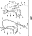
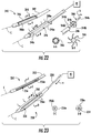
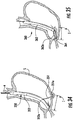
- FIG. 42 another example of a gastrectomy device is shown generally identified by reference numeral 440 which is a device for the purpose of predictably remodeling the anatomy of the stomach, particularly the greater curvature, such that the approximated anterior and posterior sides of the stomach are uniform during partial sleeve gastrectomy with repeatable results from case to case.
- Device 440 features a proximal handle assembly 442 connected to a flexible polymer main shaft 443 with a second more rigid polymer deflection shaft 444 positioned parallel to and tangent to polymer shaft 443.
- the length of the deflection shaft 444 is such that it connects proximally to the actuating member 446 of the handle assembly 442 and distally to the atraumatic polymer tip 445; both the main shaft 443 and deflection shaft 444 being attached to the atraumatic tip 445 fully distal.
- the design of both the main shaft 443 and deflection shaft 444 are each tubes of specific outer diameters and wall thicknesses, respectively. In order to achieve ease of actuation and a specific curvature of the deflection shaft 444, relief features may be included of depth and pattern to affect the necessary deployed geometry.
- a plurality of coupling brackets 447 exist along the length of the main shaft 443 in order to maintain the position of the main shaft 443 to the deflection shaft 444 over the length of the device.
- the connection of the coupling brackets 447 are such that they are mounted securely to the main shaft 443 while allowing the deflection shaft 444 to move freely, linearly.
- the location of a coupling bracket 447a dictates the resultant shape of the deflection shaft arc, and therefore can be spaced and positioned in a location(s) to maximize the effectiveness of the bow.
- a plurality of through lumens 448 in the main shaft exists at a specific distance from the distal end of the device over a specific length, and is oriented radial and perpendicular to the major axis of the shaft.
- the proximal handle assembly 442 includes a rigid, static handle 449a and a rigid, dynamic actuating member 449b. This actuating member 449b is attached to the static handle 449a in such a way as to be able to translate linearly over a specific distance.
- the deflection shaft 444 being attached to the actuation member 449b, when translating from proximal to distal, advances through the coupling brackets 447 distally. The result is that as the deflection shaft 444 is loaded in compression, being constrained by the static length of the main shaft 443, and bows into an arc 444a at the distal end of the device.
- a pressure regulator 441 that is linked to the inner lumen of the main shaft 443 through a lumen in the handle 442.
- a luer assembly 450 is also attached to the pressure regulator 441 in the handle 442 such that air can be introduced through the inner lumen of the main shaft 443 and through the lumens at the distal end 448 to achieve insufflation, or air withdrawn through this same path to achieve suction, both flow rates being controlled by the regulator 441.
- a length of LED lights 452 is housed within the ID of the deflection shaft 444 at the distal end of the device existing between the atraumatic tip 445 and the distal most coupling bracket 447a.
- the main shaft 443 of the device is introduced into the patient through the mouth, down the esophagus, cannulating the esophageal sphincter, and placed distally at the area of the antrum and pylorus.
- the user then orients the device rotationally via the proximal handle such that the main shaft 443 is oriented against the inner curve of the stomach "S" and the deflection shaft 444 is oriented toward the greater curve of the stomach.
- the actuation member on the handle assembly is then advanced distally, activating the LED light array and resulting in the bowing effect of the deflection shaft to the degree that the arc 444a of the shaft interfaces with the greater curve, putting the anterior and posterior sides of the stomach in tension and uniform about the distal geometry of the device.
- the LED array creates a visual indicator to the surgeon of the placement of the bowed deflection shaft. Additionally, this deflection results in a resultant force causing the atraumatic distal end of the main shaft 443 to conform to the angularis and antrum.
- the device allows for pressure testing of the newly remodeled sleeve by ceasing suction and allowing for insufflation of the sleeve cavity to a specific pressure. Upon completion of the procedure, the device is removed from the patient.
- This LED array feature can be included as an element in any of the embodiments.
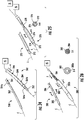
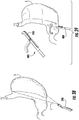
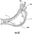
- a gastrectomy device is shown generally identified by reference numeral 460 which similar to device 440 but includes a compliant balloon feature 462 is located at the distal end of the device and can be inflated via a lumen that runs from the handle, through the ID of the main shaft 443 to the balloon.
- the main shaft 443 of the device is introduced into the patient through the mouth, down the esophagus, cannulating the esophageal sphincter, and placed distally at the area of the antrum and pylorus.
- the user then orients the device rotationally via the proximal handle such that the main shaft 443 is oriented against the inner curve of the stomach and the deflection shaft is oriented toward the greater curve of the stomach.
- the actuation member 449b on the handle assembly 442 is then advanced distally, resulting in the bowing effect of the deflection shaft to the degree that the arc 444a of the shaft interfaces with the greater curve, putting the anterior and posterior sides of the stomach in tension and uniform about the distal geometry of the device. Additionally, this deflection results in a resultant force causing the atraumatic distal end of the main shaft 443 to conform to the angularis and antrum.
- the distal balloon 462 is then inflated to a specific volume that results in the balloon filling the antrum and positioning the distal end of the device a specific distance from the pylorus. This is the starting point to begin resection.
- the device allows for pressure testing of the newly remodeled sleeve by ceasing suction and allowing for insufflation of the sleeve cavity to a specific pressure. Upon completion of the procedure, the device is removed from the patient.
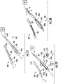
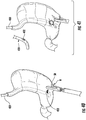
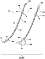
- FIG. 45 one example of a gastrectomy device is shown generally identified by reference numeral 470 which similar to devices 440 and 460 but includes a pivot stress relief feature 471 located at a specific distance from the distal end of the main shaft 443 and an actuation wire 472 that travels to and through a lumen in the handle attached to the atraumatic tip 445 and within the ID of the main shaft 443.
- reference numeral 470 similar to devices 440 and 460 but includes a pivot stress relief feature 471 located at a specific distance from the distal end of the main shaft 443 and an actuation wire 472 that travels to and through a lumen in the handle attached to the atraumatic tip 445 and within the ID of the main shaft 443.
- the main shaft 443 of the device is introduced into the patient through the mouth, down the esophagus, cannulating the esophageal sphincter, and placed distally at the area of the antrum and pylorus.
- the user then orients the device rotationally via the proximal handle such that the main shaft 443 is oriented against the inner curve of the stomach and the deflection shaft 444 is oriented toward the greater curve of the stomach.
- the actuation member 449b on the handle assembly 442 is then advanced distally, resulting in the bowing effect of the deflection shaft 444 to the degree that the arc of the shaft interfaces with the greater curve, putting the anterior and posterior sides of the stomach in tension and uniform about the distal geometry of the device.
- the actuation wire 472 is put in tension by the user, which deflects the distal end of the main shaft 443, pivoting about the pivot feature 471 and seating the distal end of the device in the antrum. Additionally, this deflection results in a resultant force causing the atraumatic distal end of the main shaft 443 to conform to the angularis and antrum.
- the device allows for pressure testing of the newly remodeled sleeve by ceasing suction and allowing for insufflation of the sleeve cavity to a specific pressure.
- tension of the actuation wire 472 is released and the device is removed from the patient.
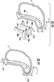
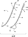
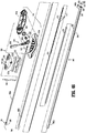
- FIGS. 46-49 illustrate an embodiment of a gastrectomy device shown generally as reference numeral 500.
- Gastrectomy device 500 is similar to gastrectomy device 460.
- Gastrectomy device 500 generally includes a handle assembly 510, an elongated member 540 extending distally from handle assembly 510, and a tube 560 associated with elongated member 540.
- Handle assembly 510 has a first section 512a and a second section 512b coupled to first section 512a and together defining a longitudinal passageway 514 that extends through handle assembly 510.
- a saddle member 516 attaches to first and second sections 512a, 512b.
- Saddle 516 has protruding, surface features 518 configured to enhance a clinician's ability to grip handle assembly 510 with one hand.
- Handle assembly 510 includes a battery housing 520 and a battery, for example, a pair of batteries 522a, 522b configured for snap-fit engagement within battery housing 520. Batteries 522a, 522b are positioned within battery housing 520.
- An actuation strip 524 is fabricated from a non-conductive material and received in battery housing 520 through a slit 526 defined in saddle 516. Actuation strip 524 isolates batteries 522a, 522b from each other such that power is not transmitted therebetween. Prior to use of gastrectomy device 500, actuation strip 524 is removed from slit 526 to electrically connect batteries 522a, 522b. Once connected, batteries 522a, 522b provide power to lights 570 as discussed in detail below.
- Handle assembly 510 includes a luer assembly 528 having a first end 530a extending outside of handle assembly 510 and a second end 530b disposed within longitudinal passageway 514 of handle assembly 510.
- First end 530a is configured for connection to a pressure source.
- Pressure source includes one of a positive pressure source, such as, for example, an insufflation source "FS" ( FIG. 48 ), or a negative pressure source, such as, for example, a vacuum source "VS” ( FIG. 48 ).
- Second end 530b is in communication with a second longitudinal channel 548 of elongated member 540.
- Luer assembly 528 has a pressure regulator 532 including a bellows 534 and a biasing member 536 disposed between luer assembly 528 and bellow 534. Pressure regulator 532 relieves pressure from within second longitudinal channel 548 upon the pressure reaching a threshold limit.
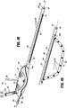
- Elongated member 540 defines a longitudinal axis "X" and has a proximal end 542a and a distal end 542b.
- Elongated member 540 is fabricated from a flexible material, for example, a suitable elastomer, adapted to conform to an interior of a stomach.
- Proximal end 542a is disposed within handle assembly 510 and distal end 542b is disposed distally of handle assembly 510.
- Elongated member 540 defines a longitudinal side window 544, a first longitudinal channel 546, a second longitudinal channel 548, and a plurality of side apertures 550.
- Side window 544 is disposed adjacent distal end 542b and has an opening large enough to accommodate passage of tube 560, as described in greater detail below.
- First longitudinal channel 546 is in communication with side window 544 and is configured for disposal of tube 560.
- Second longitudinal channel 548 of elongated member 540 is fluidly isolated from first longitudinal channel 546 by a septum (not shown) and extends in parallel relation to first longitudinal channel 546. Second longitudinal channel 548 is in fluid communication with side apertures 550 and luer assembly 528. As such, upon connecting insufflation source “FS" to first end 530a of luer assembly 528, fluid (i.e., air) may be directed from luer assembly 528 through second longitudinal channel 548, and out of side apertures 550. Additionally, upon connecting a vacuum source "VS" to first end 530a of luer assembly 528, suction may be provided at side apertures 550.
- Distal end 542b of elongated member 540 has a cap 552 attached thereto.
- Cap 552 has a cylindrical extension 554 defining a cavity 556 configured for mating engagement with a distal end 562b of tube 560.
- Cap 552 houses a GPS receiver 558. GPS receiver 558 enables a clinician to identify the precise location of a distal end of gastrectomy device 500 within a patient.
- various wireless fiduciary markers may be supported by cap 552 to determine a location of cap 552 and thus gastrectomy device 500.
- tube 560 is formed from a semi-rigid, resiliently flexible and transparent material, e.g., a suitable elastomer.
- Tube 560 defines a length greater than the length of elongated member 540 such that tube 560 can be accessed outside the patient and/or remotely of the surgical site.
- Tube 560 extends through handle assembly 510 and through first longitudinal channel 546 of elongated member 540.
- Tube 560 has a proximal end 562a extending proximally from handle assembly 510 and a distal end 562b. Proximal and distal ends 562a, 562b of tube 560 are interconnected to one another via a coupling member 563.
- proximal and distal ends 562a, 562b of tube 560 may be monolithically formed with one another.
- Proximal end 562a of tube 560 has an actuator 564.
- Actuator 564 defines a pair of depressions 566 disposed on opposite sides of actuator 564 configured for manipulation by fingers of a clinician.
- distal end 562b of tube 560 is integrally, i.e., monolithically, formed with or otherwise fixedly mated to cap 552 of elongated member 540 such that distal movement of tube 560 causes distal end 562b of tube 560 to expand or bow outwardly relative to elongated member 540. More specifically, distal movement of tube 560 causes a portion 566 of tube 560 to move from a first state, as shown in FIG. 48 , in which tube 560 is disposed within first longitudinal channel 546 of elongated member 540 and parallel with longitudinal axis "X,” to a second state, as shown in FIG.
- portion 566 of tube 560 extends outwardly from elongated member 540.
- portion 566 of tube 560 extends through longitudinal side window 544 of elongated member 540 to form an arc.
- tube 560 defines a configuration that generally complements the curvature of a greater curvature portion of a stomach. Translating tube 560 proximally relative to elongated member 540 pulls portion 566 of tube 560 into first longitudinal channel 546 through side window 544.
- gastrectomy device 500 further includes an array of lights 570 associated with tube 560.
- Lights 570 provide a visual reference of the position of tube 560 and/or gastrectomy device 500 generally.
- lights 570 may be integrally formed with tube 560.
- An elongated printed circuit board 572 is disposed within tube 560 and has lights 570 supported thereon.
- Printed circuit board 572 may be configured to frictionally fit within tube 560 such that printed circuit board 572, with lights 570 disposed thereon, move with tube 560.
- Printed circuit board 572 is made of a pliable material that permits printed circuit board 572 to flex as tube 560 moves between the first, unexpanded state, to the second, expanded state.
- a cable 574 extends from printed circuit board 572 to electrically connect lights 570 to a power source.
- Power source may be in the form of batteries, such as, for example, AAA batteries 522a, 522b, or some other power source to supply power to lights 570. It is contemplated that lights 570 may include an integral power source or may be wirelessly coupled (i.e., inductively) to a source of power that is external to the patient.
- a sheath 576 surrounds and encloses distal end 562b of tube 560 and lights 570.
- gastrectomy device 100 is inserted into a patient, such as, for example, an oral cavity of a patient and is distally advanced toward a stomach of the patient along an enteral pathway that extends from the oral cavity, through an esophagus of the patient, and into the stomach.
- Lights 570 are powered by power source 522a, 522b to illuminate tube 560 and/or gastrectomy device 500 generally.
- gastrectomy device 500 is guided along the enteral pathway via observation of the illuminated tube 560.
- Gastrectomy device 500 is selectively repositioned based on observed positions of the illuminated tube 560 along the enteral pathway.
- Guidance of gastrectomy device 500 through the esophagus is further aided by GPS receiver 558 supported in distal cap 552. Gastrectomy device 500 is further guided through the esophagus and selectively positioned within the stomach of the patient.
- a clinician grips actuator 564 supported on proximal end 562a of tube 560 and translates tube 560 distally, in the direction indicated by arrow "B" in FIG. 48 , through handle assembly 510 and first longitudinal channel 546 of elongated member 540.
- elongated member 540 As tube 560 bows outwardly towards the expanded state, elongated member 540 is urged towards and into complementary mating relation with a lesser curvature portion of the stomach, while tube 560 is urged towards and into complementary mating relation with a greater curvature portion of the stomach.
- the orientation of gastrectomy device 500 with elongated member 540 extending along the lesser curvature portion of the stomach between the esophageal sphincter and the pyloric sphincter can be readily achieved.
- this configuration of gastrectomy device 500 in the expanded state the above-described orientation of gastrectomy device 500 within the stomach is maintained despite spasms, folding, spiraling, and/or shifting of the stomach.
- suction is applied, by a vacuum source "VS," within second longitudinal channel 548 of elongated member 540 for suctioning any remaining contents within the antrum of the stomach into second longitudinal channel 548 of elongated member 540 through side apertures 550.
- Application of suction within second longitudinal channel 548 also suctions the lesser curvature portion of the stomach to an outer surface of elongated member 540, to ensure and maintain the complementary mating relation of elongated member 540 with the lesser curvature portion of the stomach.
- proximal end 562a of tube 560 is translated proximally relative to elongated member 540 such that tube 560 is pulled into first longitudinal channel 546 through side window 544 to return to the first, unexpanded state.
- elongated member 540 is maintained in the position detailed above despite contraction of tube 560.
- transection of the stomach adjacent elongated member 540 on an opposite side of elongated member 540 relative to the lesser curvature portion of the stomach may be effected in any suitable fashion, e.g., using a stapling device or other suitable device. Transection in this manner reforms the stomach to a tubular-shaped configuration that generally approximates the outer dimension of elongated member 540 and extends between the esophageal sphincter and the pyloric sphincter.
- the diameter of elongated member 540 may be selected in accordance with a desired diameter of the tubular-shape reformed stomach.
Landscapes
- Health & Medical Sciences (AREA)
- Life Sciences & Earth Sciences (AREA)
- Surgery (AREA)
- General Health & Medical Sciences (AREA)
- Public Health (AREA)
- Engineering & Computer Science (AREA)
- Biomedical Technology (AREA)
- Heart & Thoracic Surgery (AREA)
- Veterinary Medicine (AREA)
- Animal Behavior & Ethology (AREA)
- Nuclear Medicine, Radiotherapy & Molecular Imaging (AREA)
- Vascular Medicine (AREA)
- Orthopedic Medicine & Surgery (AREA)
- Medical Informatics (AREA)
- Molecular Biology (AREA)
- Obesity (AREA)
- Nursing (AREA)
- Child & Adolescent Psychology (AREA)
- Gastroenterology & Hepatology (AREA)
- Pathology (AREA)
- Oral & Maxillofacial Surgery (AREA)
- Surgical Instruments (AREA)
- Endoscopes (AREA)
- Physics & Mathematics (AREA)
- Biophysics (AREA)
- Optics & Photonics (AREA)
- Radiology & Medical Imaging (AREA)
Claims (13)
- Dispositif de gastrectomie (500) comprenant :
un élément allongé (540) ayant une extrémité proximale (542a) et une extrémité distale (542b), l'élément allongé définissant :un premier canal longitudinal (546) ayant un tube (560) s'étendant à travers celui-ci, le tube ayant une extrémité proximale et une extrémité distale ;une fenêtre latérale longitudinale (544) disposée adjacente à l'extrémité distale de l'élément allongé et étant en communication avec le premier canal longitudinal, la fenêtre étant suffisamment grande pour permettre le passage d'une partie du tube (560) à travers celle-ci ;une pluralité d'ouvertures latérales (550) ;un second canal longitudinal (548) isolé fluidiquement du premier canal longitudinal et étant en communication avec la pluralité d'ouvertures latérales (550) et configuré pour être couplé à une source de pression ; etun ensemble de lumières (570) associé au tube (560) pour fournir un éclairage ;dans lequel le tube (560) est mobile à travers l'élément allongé (540) entre un premier état, dans lequel le tube est disposé dans le premier canal longitudinal (546) contenu dans l'élément allongé, et un second état, dans lequel une partie du tube s'étend à travers la fenêtre latérale longitudinale (544) à l'extérieur de l'élément allongé. - Dispositif de gastrectomie selon la revendication 1, incluant en outre une carte de circuits imprimés allongée (572) disposée dans le tube (560) et sur laquelle est disposé l'ensemble de lumières (570).
- Dispositif de gastrectomie selon la revendication 1 ou la revendication 2, dans lequel l'ensemble de lumières (570) inclut des diodes électroluminescentes, DEL.
- Dispositif de gastrectomie selon l'une quelconque des revendications précédentes, incluant en outre un ensemble de poignée (510) couplé à l'extrémité proximale (542a) de l'élément allongé (540), le tube (560) pouvant être déplacé en translation à travers l'ensemble de poignée.
- Dispositif de gastrectomie selon la revendication 4, dans lequel l'ensemble de poignée (510) comprend une source d'alimentation connectée électriquement à l'ensemble de lumières.
- Dispositif de gastrectomie selon la revendication 5, dans lequel la source d'alimentation inclut une batterie (522a, 522b).
- Dispositif de gastrectomie selon la revendication 6, incluant en outre une bande d'activation (524) couplée de manière amovible à l'ensemble de poignée.
- Dispositif de gastrectomie selon la revendication 4, dans lequel l'ensemble de poignée inclut un ensemble Luer (528) en communication fluidique avec le second canal longitudinal (548) de l'élément allongé, l'ensemble Luer étant configuré pour une connexion à la source de pression.
- Dispositif de gastrectomie selon la revendication 8, dans lequel une source de pression est couplée au second canal longitudinal (548) pour fournir au moins une pression négative ou une pression positive au niveau de la pluralité d'ouvertures latérales (550).
- Dispositif de gastrectomie selon l'une quelconque des revendications précédentes, dans lequel l'extrémité distale (542b) de l'élément allongé (540) comporte un récepteur sans fil (558).
- Dispositif de gastrectomie selon l'une quelconque des revendications précédentes, dans lequel l'élément allongé (540) est formé d'un matériau flexible.
- Dispositif de gastrectomie selon l'une quelconque des revendications précédentes, dans lequel le tube (560) forme un arc dans le second état.
- Dispositif de gastrectomie selon l'une quelconque des revendications précédentes, dans lequel le tube (560) comporte un actionneur (564) fixé à une extrémité proximale (562a) de celui-ci.
Applications Claiming Priority (7)
| Application Number | Priority Date | Filing Date | Title |
|---|---|---|---|
| US201361901870P | 2013-11-08 | 2013-11-08 | |
| US201361902463P | 2013-11-11 | 2013-11-11 | |
| US14/491,660 US10159425B2 (en) | 2013-11-08 | 2014-09-19 | Devices and methods facilitating sleeve gastrectomy and other procedures |
| US14/492,712 US9655758B2 (en) | 2013-11-11 | 2014-09-22 | Devices and methods facilitating sleeve gastrectomy procedures |
| US201462059298P | 2014-10-03 | 2014-10-03 | |
| US14/521,571 US9801748B2 (en) | 2013-11-08 | 2014-10-23 | Devices and methods for facilitating sleeve gastrectomy procedures |
| PCT/US2014/062799 WO2015069506A1 (fr) | 2013-11-08 | 2014-10-29 | Dispositifs et procédés pour faciliter des procédures de gastrectomie longitudinale |
Publications (3)
| Publication Number | Publication Date |
|---|---|
| EP3065654A1 EP3065654A1 (fr) | 2016-09-14 |
| EP3065654A4 EP3065654A4 (fr) | 2017-08-09 |
| EP3065654B1 true EP3065654B1 (fr) | 2019-11-27 |
Family
ID=53041963
Family Applications (1)
| Application Number | Title | Priority Date | Filing Date |
|---|---|---|---|
| EP14860011.7A Active EP3065654B1 (fr) | 2013-11-08 | 2014-10-29 | Dispositifs pour faciliter des procédures de gastrectomie longitudinale |
Country Status (7)
| Country | Link |
|---|---|
| US (2) | US9801748B2 (fr) |
| EP (1) | EP3065654B1 (fr) |
| JP (2) | JP6560204B2 (fr) |
| AU (1) | AU2014347120A1 (fr) |
| CA (1) | CA2927940A1 (fr) |
| ES (1) | ES2765323T3 (fr) |
| WO (1) | WO2015069506A1 (fr) |
Families Citing this family (23)
| Publication number | Priority date | Publication date | Assignee | Title |
|---|---|---|---|---|
| EP3054860B1 (fr) | 2013-10-10 | 2020-07-01 | Nitinotes Ltd. | Gastroplastie par manchon endoluminal |
| US10779979B2 (en) | 2013-10-10 | 2020-09-22 | Nitinotes Ltd. | Endoluminal sleeve gastroplasty |
| US9801748B2 (en) * | 2013-11-08 | 2017-10-31 | Covidien Lp | Devices and methods for facilitating sleeve gastrectomy procedures |
| US9655758B2 (en) | 2013-11-11 | 2017-05-23 | Covidien Lp | Devices and methods facilitating sleeve gastrectomy procedures |
| US10278707B2 (en) | 2013-12-17 | 2019-05-07 | Standard Bariatrics, Inc. | Resection line guide for a medical procedure and method of using same |
| US9936953B2 (en) | 2014-03-29 | 2018-04-10 | Standard Bariatrics, Inc. | End effectors, surgical stapling devices, and methods of using same |
| CA2944383C (fr) | 2014-03-29 | 2019-09-17 | Standard Bariatrics, Inc. | Dispositifs d'agrafage chirurgical a effecteurs d'extremite, et leurs procedes d'utilisation |
| WO2017011085A1 (fr) * | 2015-07-15 | 2017-01-19 | Cook Medical Technologies Llc | Ensemble dispositif médical gastrique éclairé et procédé correspondant |
| US9717515B1 (en) * | 2015-08-10 | 2017-08-01 | MW Support Services, LLC | Medical device for sleeve gastrectomy surgery |
| US10285837B1 (en) | 2015-09-16 | 2019-05-14 | Standard Bariatrics, Inc. | Systems and methods for measuring volume of potential sleeve in a sleeve gastrectomy |
| WO2019036490A1 (fr) | 2017-08-14 | 2019-02-21 | Standard Bariatrics, Inc. | Effecteurs d'extrémité, dispositifs d'agrafage chirurgical, et leurs procédés d'utilisation |
| WO2019218066A1 (fr) | 2018-05-15 | 2019-11-21 | Ballast Medical Inc. | Techniques améliorées pour l'introduction et l'extraction d'une bougie pendant une gastroplastie |
| US20200261251A1 (en) * | 2019-02-19 | 2020-08-20 | Covidien Lp | Gastric positioning device |
| EP4054492A4 (fr) * | 2019-11-04 | 2023-11-01 | Standard Bariatrics, Inc. | Systèmes et procédés de réalisation d'une chirurgie en utilisant la rétractation de tension de la loi de laplace pendant la chirurgie |
| JP7415473B2 (ja) | 2019-11-20 | 2024-01-17 | 住友ベークライト株式会社 | ガイドチューブ及びガイドチューブセット |
| US11701095B2 (en) * | 2019-11-21 | 2023-07-18 | Covidien Lp | Robotic surgical systems and methods of use thereof |
| JP7415758B2 (ja) | 2020-04-10 | 2024-01-17 | 住友ベークライト株式会社 | ガイドチューブ |
| DE102020113465A1 (de) | 2020-05-19 | 2021-11-25 | Universitätsmedizin der Johannes Gutenberg-Universität Mainz, Körperschaft des öffentlichen Rechts | Vorrichtung zur Unterstützung der Ausleuchtung und der anatomischen Grenzdarstellung bei medizinischen Eingriffen |
| US11950839B2 (en) * | 2020-07-30 | 2024-04-09 | Sd Cardiothoracic Innovations, Llc | Multiple vacuum device for medical fixture placement |
| IT202000018649A1 (it) * | 2020-07-30 | 2022-01-30 | Sapi Med S P A | Dispositivo medicale |
| KR102539371B1 (ko) * | 2020-11-09 | 2023-06-08 | 아주대학교산학협력단 | 위소매 절제술 보조 장치 |
| KR102492193B1 (ko) * | 2020-12-03 | 2023-01-26 | 고려대학교 산학협력단 | 흡입 및 위치조절이 가능한 위소매절제술용 위관 |
| CA3212625A1 (fr) | 2021-03-23 | 2022-09-29 | Adam R. Dunki-Jacobs | Systemes et procedes pour empecher la migration de tissu dans des agrafeuses chirurgicales |
Family Cites Families (76)
| Publication number | Priority date | Publication date | Assignee | Title |
|---|---|---|---|---|
| US2067031A (en) | 1934-03-23 | 1937-01-05 | Wappler Frederick Charles | Instrument for insertion into constricted body cavities |
| US3739784A (en) | 1971-12-01 | 1973-06-19 | Olympus Optical Co | Surgical instrument |
| US4328805A (en) | 1980-10-03 | 1982-05-11 | Akopov Ernest M | Method of suturing the organs of the gastrointestinal tract |
| US4403604A (en) | 1982-05-13 | 1983-09-13 | Wilkinson Lawrence H | Gastric pouch |
| US5179938A (en) | 1983-02-17 | 1993-01-19 | The Trylon Corporation | Apparatus for endoscopic examination of body cavity using chemiluminescent light source |
| US4774949A (en) | 1983-06-14 | 1988-10-04 | Fogarty Thomas J | Deflector guiding catheter |
| US4744363A (en) | 1986-07-07 | 1988-05-17 | Hasson Harrith M | Intra-abdominal organ stabilizer, retractor and tissue manipulator |
| IL103445A (en) | 1991-10-18 | 1997-04-15 | Ethicon Inc | Endoscopic tissue manipulator |
| US5401241A (en) | 1992-05-07 | 1995-03-28 | Inamed Development Co. | Duodenal intubation catheter |
| US5246456A (en) | 1992-06-08 | 1993-09-21 | Wilkinson Lawrence H | Fenestrated gastric pouch |
| US5297536A (en) | 1992-08-25 | 1994-03-29 | Wilk Peter J | Method for use in intra-abdominal surgery |
| US5458131A (en) | 1992-08-25 | 1995-10-17 | Wilk; Peter J. | Method for use in intra-abdominal surgery |
| US5325848A (en) | 1992-09-10 | 1994-07-05 | Ethicon, Inc. | Endoscopic tissue manipulator with expandable frame |
| US5382231A (en) | 1993-02-02 | 1995-01-17 | Shlain; Leonard M. | Method for transesophageal retraction of the stomach |
| FR2708456B1 (fr) | 1993-08-06 | 1995-09-08 | Jarrossay Ets Yves | Ecarteur. |
| US5465709A (en) | 1993-11-10 | 1995-11-14 | Advanced Medical Products Inc. | Illuminated vaginal speculum |
| US5718666A (en) | 1996-02-29 | 1998-02-17 | Bioenterics Corporation | Transilluminating bougie |
| US5876427A (en) * | 1997-01-29 | 1999-03-02 | Light Sciences Limited Partnership | Compact flexible circuit configuration |
| US6371637B1 (en) * | 1999-02-26 | 2002-04-16 | Radiantz, Inc. | Compact, flexible, LED array |
| US6572627B2 (en) | 2001-01-08 | 2003-06-03 | Shlomo Gabbay | System to inhibit and/or control expansion of anatomical features |
| US7083629B2 (en) | 2001-05-30 | 2006-08-01 | Satiety, Inc. | Overtube apparatus for insertion into a body |
| WO2003075979A2 (fr) | 2002-03-06 | 2003-09-18 | Simon James S | Appareils medicaux illumines par chimiluminescence |
| US6773440B2 (en) | 2002-07-02 | 2004-08-10 | Satiety, Inc. | Method and device for use in tissue approximation and fixation |
| US7220237B2 (en) | 2002-10-23 | 2007-05-22 | Satiety, Inc. | Method and device for use in endoscopic organ procedures |
| US20040249367A1 (en) * | 2003-01-15 | 2004-12-09 | Usgi Medical Corp. | Endoluminal tool deployment system |
| US20040199052A1 (en) | 2003-04-01 | 2004-10-07 | Scimed Life Systems, Inc. | Endoscopic imaging system |
| US7052456B2 (en) * | 2003-04-16 | 2006-05-30 | Simon James S | Airway products having LEDs |
| US7128442B2 (en) * | 2003-05-09 | 2006-10-31 | Kian Shin Lee | Illumination unit with a solid-state light generating source, a flexible substrate, and a flexible and optically transparent encapsulant |
| DE602004028390D1 (de) | 2003-10-23 | 2010-09-09 | Proxy Biomedical Ltd | Magenverengungsvorrichtung |
| US7261730B2 (en) * | 2003-11-14 | 2007-08-28 | Lumerx, Inc. | Phototherapy device and system |
| US7703459B2 (en) | 2004-03-09 | 2010-04-27 | Usgi Medical, Inc. | Apparatus and methods for mapping out endoluminal gastrointestinal surgery |
| US8992420B2 (en) * | 2004-04-14 | 2015-03-31 | Usgi Medical, Inc. | Methods and apparatus for off-axis visualization |
| US8277373B2 (en) | 2004-04-14 | 2012-10-02 | Usgi Medical, Inc. | Methods and apparaus for off-axis visualization |
| US7918869B2 (en) | 2004-05-07 | 2011-04-05 | Usgi Medical, Inc. | Methods and apparatus for performing endoluminal gastroplasty |
| US20060106288A1 (en) | 2004-11-17 | 2006-05-18 | Roth Alex T | Remote tissue retraction device |
| US7976518B2 (en) | 2005-01-13 | 2011-07-12 | Corpak Medsystems, Inc. | Tubing assembly and signal generator placement control device and method for use with catheter guidance systems |
| WO2006081134A2 (fr) | 2005-01-26 | 2006-08-03 | Wilk Patent, Llc | Procedures et dispositif medicaux intra-abdominaux |
| US7153131B2 (en) | 2005-02-07 | 2006-12-26 | Crohn Enterprises Ltd. | Intraoral illumination device |
| JP2008536552A (ja) * | 2005-04-11 | 2008-09-11 | ユーエスジーアイ メディカル インク. | 軸外可視化のための方法および装置 |
| US20060241344A1 (en) | 2005-04-12 | 2006-10-26 | Wilk Patent, Llc | Intra-abdominal surgical method and associated apparatus |
| US20060241570A1 (en) | 2005-04-22 | 2006-10-26 | Wilk Patent, Llc | Intra-abdominal medical method |
| WO2007002084A2 (fr) | 2005-06-20 | 2007-01-04 | Susan Russo | Systeme tube medical a detection de position |
| US7779845B2 (en) | 2005-08-05 | 2010-08-24 | Ethicon Endo-Surgery, Inc. | Method and apparatus for endoscopically performing gastric reduction surgery |
| US20070060795A1 (en) * | 2005-09-14 | 2007-03-15 | Spotlight Surgical, Inc. | Lighted surgical retractors with LED illumination light engines |
| US20070073098A1 (en) | 2005-09-23 | 2007-03-29 | Ellipse Technologies, Inc. | Method and apparatus for adjusting body lumens |
| US7374309B2 (en) * | 2006-04-04 | 2008-05-20 | Horizon Group - Usa, Inc. | Waterproof, miniature light-emitting diode (LED) device |
| US7384392B2 (en) * | 2006-05-22 | 2008-06-10 | Ardeshir Bayat | Disposable expandable cordless lighted retractor |
| US8012089B2 (en) * | 2006-05-22 | 2011-09-06 | Ardeshir Bayat | Disposable expandable cordless lighted retractor |
| MX2009003931A (es) * | 2006-10-11 | 2009-04-24 | Light Sciences Oncology Inc | Sistema de suministro de luz. |
| ES2326937B2 (es) | 2006-12-27 | 2010-06-09 | Jesus Javier Castellanos Monedero | Cateter modificado. |
| JP4563446B2 (ja) * | 2006-12-28 | 2010-10-13 | オリンパスメディカルシステムズ株式会社 | 胃の処置システム |
| USD622676S1 (en) * | 2007-03-19 | 2010-08-31 | Nichia Corporation | LED display device |
| WO2008130582A2 (fr) * | 2007-04-17 | 2008-10-30 | Surgiquest, Incorporated | Procédés et dispositifs chirurgicaux endoluminaux et transluminaux |
| US8192448B2 (en) | 2007-11-19 | 2012-06-05 | Tyco Healthcare Group Lp | Natural orifice bariatric procedure and apparatus for use therewith |
| EP2240086B1 (fr) | 2008-02-01 | 2018-08-01 | Ballast Medical Inc. | Dispositifs permettant la réalisation d'une gastroplastie |
| US8147502B2 (en) | 2008-05-01 | 2012-04-03 | Ethicon Endo-Surgery, Inc. | Gastric coil manipulator |
| US10350050B2 (en) | 2008-05-01 | 2019-07-16 | Ethicon Endo-Surgery, Inc. | Method for gastric volume reduction surgery |
| WO2010042493A1 (fr) * | 2008-10-06 | 2010-04-15 | Allergan, Inc. | Bande gastrique mécanique avec coussins |
| CN201365906Y (zh) | 2009-02-13 | 2009-12-23 | 殷秀芬 | 胃液ph值检测装置 |
| US9050174B2 (en) | 2009-07-23 | 2015-06-09 | Reshape Medical, Inc. | Deflation and removal of implantable medical devices |
| US20110288576A1 (en) | 2010-05-21 | 2011-11-24 | Jason Lane Hoffman | Hoffy Bougie Gastric Tube |
| FR2961703B1 (fr) * | 2010-06-23 | 2012-07-13 | Medical Innovation Dev | Sonde orogastrique de gastrectomie longitudinale |
| US20120165842A1 (en) * | 2010-12-22 | 2012-06-28 | Ethicon Endo-Surgery, Inc. | Endoluminal fold creation |
| US20120239061A1 (en) | 2011-03-15 | 2012-09-20 | Mathur Sandip V | Endoscopic full thickness gastric reduction apparatus and method |
| WO2012138737A1 (fr) | 2011-04-04 | 2012-10-11 | Roger De La Torre | Appareil et procédé de création d'une lumière de forme et de taille voulues dans un organe viscéral creux à partir de tissu de cet organe |
| WO2012141679A1 (fr) * | 2011-04-11 | 2012-10-18 | Hassan Chandra | Technique(s) et/ou dispositif(s) chirurgicaux |
| US20130197313A1 (en) * | 2012-01-31 | 2013-08-01 | Shaw P. Wan | Surgical retractor with light |
| US20150080647A1 (en) | 2012-02-16 | 2015-03-19 | Lowell Albert Wetter | Internal Organ Plication Device and Method |
| CN102626536A (zh) | 2012-03-31 | 2012-08-08 | 泰安市中心医院 | 临床护理用多用途三通插接件及其使用方法 |
| JP3178309U (ja) | 2012-05-07 | 2012-09-13 | 仁 戸田 | コンドームを蓄尿バッグの導尿管に繋ぐための連結管セット |
| WO2014062881A1 (fr) | 2012-10-19 | 2014-04-24 | Covidien Lp | Dispositifs et procédés facilitant des interventions de gastrectomie longitudinale |
| US20150045613A1 (en) * | 2013-05-16 | 2015-02-12 | Norton EDWARDS | Malleable Surgical Assistance Devices |
| US9801748B2 (en) * | 2013-11-08 | 2017-10-31 | Covidien Lp | Devices and methods for facilitating sleeve gastrectomy procedures |
| US9655758B2 (en) | 2013-11-11 | 2017-05-23 | Covidien Lp | Devices and methods facilitating sleeve gastrectomy procedures |
| WO2015187857A1 (fr) * | 2014-06-03 | 2015-12-10 | The Regents Of The University Of California | Suivi de dispositif médical au moyen d'un réseau de capteurs à base de rf |
| US9629741B2 (en) * | 2014-07-18 | 2017-04-25 | Covidien Lp | Gastric tubes and methods of use |
-
2014
- 2014-10-23 US US14/521,571 patent/US9801748B2/en active Active
- 2014-10-29 AU AU2014347120A patent/AU2014347120A1/en not_active Abandoned
- 2014-10-29 WO PCT/US2014/062799 patent/WO2015069506A1/fr active Application Filing
- 2014-10-29 EP EP14860011.7A patent/EP3065654B1/fr active Active
- 2014-10-29 JP JP2016526863A patent/JP6560204B2/ja not_active Expired - Fee Related
- 2014-10-29 ES ES14860011T patent/ES2765323T3/es active Active
- 2014-10-29 CA CA2927940A patent/CA2927940A1/fr not_active Abandoned
-
2017
- 2017-10-30 US US15/798,338 patent/US10524947B2/en active Active
-
2018
- 2018-10-12 JP JP2018193397A patent/JP2019034173A/ja active Pending
Non-Patent Citations (1)
| Title |
|---|
| None * |
Also Published As
| Publication number | Publication date |
|---|---|
| US20180049902A1 (en) | 2018-02-22 |
| JP2019034173A (ja) | 2019-03-07 |
| US9801748B2 (en) | 2017-10-31 |
| JP6560204B2 (ja) | 2019-08-14 |
| ES2765323T3 (es) | 2020-06-08 |
| JP2016534800A (ja) | 2016-11-10 |
| US10524947B2 (en) | 2020-01-07 |
| CA2927940A1 (fr) | 2015-05-14 |
| EP3065654A1 (fr) | 2016-09-14 |
| WO2015069506A1 (fr) | 2015-05-14 |
| AU2014347120A1 (en) | 2016-05-05 |
| US20150133740A1 (en) | 2015-05-14 |
| EP3065654A4 (fr) | 2017-08-09 |
Similar Documents
| Publication | Publication Date | Title |
|---|---|---|
| EP3065654B1 (fr) | Dispositifs pour faciliter des procédures de gastrectomie longitudinale | |
| US11432953B2 (en) | Devices and methods facilitating sleeve gastrectomy procedures | |
| US11553855B2 (en) | Devices and methods facilitating sleeve gastrectomy and other procedures | |
| US8770460B2 (en) | Shield for surgical stapler and method of use | |
| US10603465B2 (en) | Illuminated gastric tubes and methods of use | |
| US11311401B2 (en) | Gastric tubes and methods of use | |
| WO2011087848A1 (fr) | Protection pour agrafeuse chirurgicale et son procede d'utilisation |
Legal Events
| Date | Code | Title | Description |
|---|---|---|---|
| PUAI | Public reference made under article 153(3) epc to a published international application that has entered the european phase |
Free format text: ORIGINAL CODE: 0009012 |
|
| 17P | Request for examination filed |
Effective date: 20160607 |
|
| AK | Designated contracting states |
Kind code of ref document: A1 Designated state(s): AL AT BE BG CH CY CZ DE DK EE ES FI FR GB GR HR HU IE IS IT LI LT LU LV MC MK MT NL NO PL PT RO RS SE SI SK SM TR |
|
| AX | Request for extension of the european patent |
Extension state: BA ME |
|
| DAX | Request for extension of the european patent (deleted) | ||
| A4 | Supplementary search report drawn up and despatched |
Effective date: 20170712 |
|
| RIC1 | Information provided on ipc code assigned before grant |
Ipc: A61F 5/00 20060101ALI20170706BHEP Ipc: A61B 90/30 20160101AFI20170706BHEP |
|
| STAA | Information on the status of an ep patent application or granted ep patent |
Free format text: STATUS: EXAMINATION IS IN PROGRESS |
|
| 17Q | First examination report despatched |
Effective date: 20180723 |
|
| REG | Reference to a national code |
Ref country code: DE Ref legal event code: R079 Ref document number: 602014057636 Country of ref document: DE Free format text: PREVIOUS MAIN CLASS: A61B0017320500 Ipc: A61B0017020000 |
|
| GRAP | Despatch of communication of intention to grant a patent |
Free format text: ORIGINAL CODE: EPIDOSNIGR1 |
|
| STAA | Information on the status of an ep patent application or granted ep patent |
Free format text: STATUS: GRANT OF PATENT IS INTENDED |
|
| RIC1 | Information provided on ipc code assigned before grant |
Ipc: A61B 90/30 20160101ALI20190508BHEP Ipc: A61B 17/02 20060101AFI20190508BHEP Ipc: A61F 5/00 20060101ALI20190508BHEP |
|
| INTG | Intention to grant announced |
Effective date: 20190605 |
|
| GRAS | Grant fee paid |
Free format text: ORIGINAL CODE: EPIDOSNIGR3 |
|
| GRAA | (expected) grant |
Free format text: ORIGINAL CODE: 0009210 |
|
| STAA | Information on the status of an ep patent application or granted ep patent |
Free format text: STATUS: THE PATENT HAS BEEN GRANTED |
|
| AK | Designated contracting states |
Kind code of ref document: B1 Designated state(s): AL AT BE BG CH CY CZ DE DK EE ES FI FR GB GR HR HU IE IS IT LI LT LU LV MC MK MT NL NO PL PT RO RS SE SI SK SM TR |
|
| REG | Reference to a national code |
Ref country code: GB Ref legal event code: FG4D |
|
| REG | Reference to a national code |
Ref country code: CH Ref legal event code: EP |
|
| REG | Reference to a national code |
Ref country code: AT Ref legal event code: REF Ref document number: 1205830 Country of ref document: AT Kind code of ref document: T Effective date: 20191215 |
|
| REG | Reference to a national code |
Ref country code: DE Ref legal event code: R096 Ref document number: 602014057636 Country of ref document: DE |
|
| REG | Reference to a national code |
Ref country code: IE Ref legal event code: FG4D |
|
| REG | Reference to a national code |
Ref country code: NL Ref legal event code: MP Effective date: 20191127 |
|
| REG | Reference to a national code |
Ref country code: LT Ref legal event code: MG4D |
|
| PG25 | Lapsed in a contracting state [announced via postgrant information from national office to epo] |
Ref country code: BG Free format text: LAPSE BECAUSE OF FAILURE TO SUBMIT A TRANSLATION OF THE DESCRIPTION OR TO PAY THE FEE WITHIN THE PRESCRIBED TIME-LIMIT Effective date: 20200227 Ref country code: GR Free format text: LAPSE BECAUSE OF FAILURE TO SUBMIT A TRANSLATION OF THE DESCRIPTION OR TO PAY THE FEE WITHIN THE PRESCRIBED TIME-LIMIT Effective date: 20200228 Ref country code: NO Free format text: LAPSE BECAUSE OF FAILURE TO SUBMIT A TRANSLATION OF THE DESCRIPTION OR TO PAY THE FEE WITHIN THE PRESCRIBED TIME-LIMIT Effective date: 20200227 Ref country code: NL Free format text: LAPSE BECAUSE OF FAILURE TO SUBMIT A TRANSLATION OF THE DESCRIPTION OR TO PAY THE FEE WITHIN THE PRESCRIBED TIME-LIMIT Effective date: 20191127 Ref country code: LT Free format text: LAPSE BECAUSE OF FAILURE TO SUBMIT A TRANSLATION OF THE DESCRIPTION OR TO PAY THE FEE WITHIN THE PRESCRIBED TIME-LIMIT Effective date: 20191127 Ref country code: LV Free format text: LAPSE BECAUSE OF FAILURE TO SUBMIT A TRANSLATION OF THE DESCRIPTION OR TO PAY THE FEE WITHIN THE PRESCRIBED TIME-LIMIT Effective date: 20191127 Ref country code: SE Free format text: LAPSE BECAUSE OF FAILURE TO SUBMIT A TRANSLATION OF THE DESCRIPTION OR TO PAY THE FEE WITHIN THE PRESCRIBED TIME-LIMIT Effective date: 20191127 Ref country code: FI Free format text: LAPSE BECAUSE OF FAILURE TO SUBMIT A TRANSLATION OF THE DESCRIPTION OR TO PAY THE FEE WITHIN THE PRESCRIBED TIME-LIMIT Effective date: 20191127 |
|
| PG25 | Lapsed in a contracting state [announced via postgrant information from national office to epo] |
Ref country code: IS Free format text: LAPSE BECAUSE OF FAILURE TO SUBMIT A TRANSLATION OF THE DESCRIPTION OR TO PAY THE FEE WITHIN THE PRESCRIBED TIME-LIMIT Effective date: 20200327 Ref country code: RS Free format text: LAPSE BECAUSE OF FAILURE TO SUBMIT A TRANSLATION OF THE DESCRIPTION OR TO PAY THE FEE WITHIN THE PRESCRIBED TIME-LIMIT Effective date: 20191127 Ref country code: HR Free format text: LAPSE BECAUSE OF FAILURE TO SUBMIT A TRANSLATION OF THE DESCRIPTION OR TO PAY THE FEE WITHIN THE PRESCRIBED TIME-LIMIT Effective date: 20191127 |
|
| REG | Reference to a national code |
Ref country code: ES Ref legal event code: FG2A Ref document number: 2765323 Country of ref document: ES Kind code of ref document: T3 Effective date: 20200608 |
|
| PG25 | Lapsed in a contracting state [announced via postgrant information from national office to epo] |
Ref country code: AL Free format text: LAPSE BECAUSE OF FAILURE TO SUBMIT A TRANSLATION OF THE DESCRIPTION OR TO PAY THE FEE WITHIN THE PRESCRIBED TIME-LIMIT Effective date: 20191127 |
|
| PG25 | Lapsed in a contracting state [announced via postgrant information from national office to epo] |
Ref country code: DK Free format text: LAPSE BECAUSE OF FAILURE TO SUBMIT A TRANSLATION OF THE DESCRIPTION OR TO PAY THE FEE WITHIN THE PRESCRIBED TIME-LIMIT Effective date: 20191127 Ref country code: CZ Free format text: LAPSE BECAUSE OF FAILURE TO SUBMIT A TRANSLATION OF THE DESCRIPTION OR TO PAY THE FEE WITHIN THE PRESCRIBED TIME-LIMIT Effective date: 20191127 Ref country code: PT Free format text: LAPSE BECAUSE OF FAILURE TO SUBMIT A TRANSLATION OF THE DESCRIPTION OR TO PAY THE FEE WITHIN THE PRESCRIBED TIME-LIMIT Effective date: 20200419 Ref country code: EE Free format text: LAPSE BECAUSE OF FAILURE TO SUBMIT A TRANSLATION OF THE DESCRIPTION OR TO PAY THE FEE WITHIN THE PRESCRIBED TIME-LIMIT Effective date: 20191127 Ref country code: RO Free format text: LAPSE BECAUSE OF FAILURE TO SUBMIT A TRANSLATION OF THE DESCRIPTION OR TO PAY THE FEE WITHIN THE PRESCRIBED TIME-LIMIT Effective date: 20191127 |
|
| REG | Reference to a national code |
Ref country code: DE Ref legal event code: R097 Ref document number: 602014057636 Country of ref document: DE |
|
| PG25 | Lapsed in a contracting state [announced via postgrant information from national office to epo] |
Ref country code: SK Free format text: LAPSE BECAUSE OF FAILURE TO SUBMIT A TRANSLATION OF THE DESCRIPTION OR TO PAY THE FEE WITHIN THE PRESCRIBED TIME-LIMIT Effective date: 20191127 Ref country code: SM Free format text: LAPSE BECAUSE OF FAILURE TO SUBMIT A TRANSLATION OF THE DESCRIPTION OR TO PAY THE FEE WITHIN THE PRESCRIBED TIME-LIMIT Effective date: 20191127 |
|
| REG | Reference to a national code |
Ref country code: AT Ref legal event code: MK05 Ref document number: 1205830 Country of ref document: AT Kind code of ref document: T Effective date: 20191127 |
|
| PLBE | No opposition filed within time limit |
Free format text: ORIGINAL CODE: 0009261 |
|
| STAA | Information on the status of an ep patent application or granted ep patent |
Free format text: STATUS: NO OPPOSITION FILED WITHIN TIME LIMIT |
|
| 26N | No opposition filed |
Effective date: 20200828 |
|
| PG25 | Lapsed in a contracting state [announced via postgrant information from national office to epo] |
Ref country code: PL Free format text: LAPSE BECAUSE OF FAILURE TO SUBMIT A TRANSLATION OF THE DESCRIPTION OR TO PAY THE FEE WITHIN THE PRESCRIBED TIME-LIMIT Effective date: 20191127 Ref country code: SI Free format text: LAPSE BECAUSE OF FAILURE TO SUBMIT A TRANSLATION OF THE DESCRIPTION OR TO PAY THE FEE WITHIN THE PRESCRIBED TIME-LIMIT Effective date: 20191127 Ref country code: AT Free format text: LAPSE BECAUSE OF FAILURE TO SUBMIT A TRANSLATION OF THE DESCRIPTION OR TO PAY THE FEE WITHIN THE PRESCRIBED TIME-LIMIT Effective date: 20191127 |
|
| PGFP | Annual fee paid to national office [announced via postgrant information from national office to epo] |
Ref country code: IT Payment date: 20200917 Year of fee payment: 7 |
|
| REG | Reference to a national code |
Ref country code: CH Ref legal event code: PL |
|
| PG25 | Lapsed in a contracting state [announced via postgrant information from national office to epo] |
Ref country code: LU Free format text: LAPSE BECAUSE OF NON-PAYMENT OF DUE FEES Effective date: 20201029 Ref country code: MC Free format text: LAPSE BECAUSE OF FAILURE TO SUBMIT A TRANSLATION OF THE DESCRIPTION OR TO PAY THE FEE WITHIN THE PRESCRIBED TIME-LIMIT Effective date: 20191127 |
|
| REG | Reference to a national code |
Ref country code: BE Ref legal event code: MM Effective date: 20201031 |
|
| PG25 | Lapsed in a contracting state [announced via postgrant information from national office to epo] |
Ref country code: LI Free format text: LAPSE BECAUSE OF NON-PAYMENT OF DUE FEES Effective date: 20201031 Ref country code: CH Free format text: LAPSE BECAUSE OF NON-PAYMENT OF DUE FEES Effective date: 20201031 Ref country code: BE Free format text: LAPSE BECAUSE OF NON-PAYMENT OF DUE FEES Effective date: 20201031 |
|
| PG25 | Lapsed in a contracting state [announced via postgrant information from national office to epo] |
Ref country code: TR Free format text: LAPSE BECAUSE OF FAILURE TO SUBMIT A TRANSLATION OF THE DESCRIPTION OR TO PAY THE FEE WITHIN THE PRESCRIBED TIME-LIMIT Effective date: 20191127 Ref country code: MT Free format text: LAPSE BECAUSE OF FAILURE TO SUBMIT A TRANSLATION OF THE DESCRIPTION OR TO PAY THE FEE WITHIN THE PRESCRIBED TIME-LIMIT Effective date: 20191127 Ref country code: CY Free format text: LAPSE BECAUSE OF FAILURE TO SUBMIT A TRANSLATION OF THE DESCRIPTION OR TO PAY THE FEE WITHIN THE PRESCRIBED TIME-LIMIT Effective date: 20191127 |
|
| PG25 | Lapsed in a contracting state [announced via postgrant information from national office to epo] |
Ref country code: MK Free format text: LAPSE BECAUSE OF FAILURE TO SUBMIT A TRANSLATION OF THE DESCRIPTION OR TO PAY THE FEE WITHIN THE PRESCRIBED TIME-LIMIT Effective date: 20191127 |
|
| PG25 | Lapsed in a contracting state [announced via postgrant information from national office to epo] |
Ref country code: IT Free format text: LAPSE BECAUSE OF NON-PAYMENT OF DUE FEES Effective date: 20211029 |
|
| PGFP | Annual fee paid to national office [announced via postgrant information from national office to epo] |
Ref country code: IE Payment date: 20220921 Year of fee payment: 9 Ref country code: GB Payment date: 20220922 Year of fee payment: 9 |
|
| PGFP | Annual fee paid to national office [announced via postgrant information from national office to epo] |
Ref country code: FR Payment date: 20220922 Year of fee payment: 9 |
|
| PGFP | Annual fee paid to national office [announced via postgrant information from national office to epo] |
Ref country code: ES Payment date: 20221102 Year of fee payment: 9 Ref country code: DE Payment date: 20220920 Year of fee payment: 9 |