EP3063835B1 - Verbindungsanordnung zum verbinden von wenigstens einer spannungsquelle und/oder spannungssenke in form einer zelle einer traktionsbatterie an eine externe elektrische komponente und elektrische anordnung mit einer verbindungsanordnung - Google Patents
Verbindungsanordnung zum verbinden von wenigstens einer spannungsquelle und/oder spannungssenke in form einer zelle einer traktionsbatterie an eine externe elektrische komponente und elektrische anordnung mit einer verbindungsanordnung Download PDFInfo
- Publication number
- EP3063835B1 EP3063835B1 EP14789307.7A EP14789307A EP3063835B1 EP 3063835 B1 EP3063835 B1 EP 3063835B1 EP 14789307 A EP14789307 A EP 14789307A EP 3063835 B1 EP3063835 B1 EP 3063835B1
- Authority
- EP
- European Patent Office
- Prior art keywords
- cell
- connection
- connection line
- arrangement
- voltage
- Prior art date
- Legal status (The legal status is an assumption and is not a legal conclusion. Google has not performed a legal analysis and makes no representation as to the accuracy of the status listed.)
- Active
Links
Images


Classifications
-
- H—ELECTRICITY
- H01—ELECTRIC ELEMENTS
- H01R—ELECTRICALLY-CONDUCTIVE CONNECTIONS; STRUCTURAL ASSOCIATIONS OF A PLURALITY OF MUTUALLY-INSULATED ELECTRICAL CONNECTING ELEMENTS; COUPLING DEVICES; CURRENT COLLECTORS
- H01R12/00—Structural associations of a plurality of mutually-insulated electrical connecting elements, specially adapted for printed circuits, e.g. printed circuit boards [PCB], flat or ribbon cables, or like generally planar structures, e.g. terminal strips, terminal blocks; Coupling devices specially adapted for printed circuits, flat or ribbon cables, or like generally planar structures; Terminals specially adapted for contact with, or insertion into, printed circuits, flat or ribbon cables, or like generally planar structures
- H01R12/50—Fixed connections
- H01R12/59—Fixed connections for flexible printed circuits, flat or ribbon cables or like structures
- H01R12/62—Fixed connections for flexible printed circuits, flat or ribbon cables or like structures connecting to rigid printed circuits or like structures
-
- H—ELECTRICITY
- H01—ELECTRIC ELEMENTS
- H01R—ELECTRICALLY-CONDUCTIVE CONNECTIONS; STRUCTURAL ASSOCIATIONS OF A PLURALITY OF MUTUALLY-INSULATED ELECTRICAL CONNECTING ELEMENTS; COUPLING DEVICES; CURRENT COLLECTORS
- H01R12/00—Structural associations of a plurality of mutually-insulated electrical connecting elements, specially adapted for printed circuits, e.g. printed circuit boards [PCB], flat or ribbon cables, or like generally planar structures, e.g. terminal strips, terminal blocks; Coupling devices specially adapted for printed circuits, flat or ribbon cables, or like generally planar structures; Terminals specially adapted for contact with, or insertion into, printed circuits, flat or ribbon cables, or like generally planar structures
- H01R12/50—Fixed connections
- H01R12/59—Fixed connections for flexible printed circuits, flat or ribbon cables or like structures
- H01R12/65—Fixed connections for flexible printed circuits, flat or ribbon cables or like structures characterised by the terminal
- H01R12/69—Fixed connections for flexible printed circuits, flat or ribbon cables or like structures characterised by the terminal deformable terminals, e.g. crimping terminals
-
- H—ELECTRICITY
- H01—ELECTRIC ELEMENTS
- H01M—PROCESSES OR MEANS, e.g. BATTERIES, FOR THE DIRECT CONVERSION OF CHEMICAL ENERGY INTO ELECTRICAL ENERGY
- H01M10/00—Secondary cells; Manufacture thereof
- H01M10/42—Methods or arrangements for servicing or maintenance of secondary cells or secondary half-cells
- H01M10/48—Accumulators combined with arrangements for measuring, testing or indicating the condition of cells, e.g. the level or density of the electrolyte
- H01M10/482—Accumulators combined with arrangements for measuring, testing or indicating the condition of cells, e.g. the level or density of the electrolyte for several batteries or cells simultaneously or sequentially
-
- H—ELECTRICITY
- H01—ELECTRIC ELEMENTS
- H01M—PROCESSES OR MEANS, e.g. BATTERIES, FOR THE DIRECT CONVERSION OF CHEMICAL ENERGY INTO ELECTRICAL ENERGY
- H01M50/00—Constructional details or processes of manufacture of the non-active parts of electrochemical cells other than fuel cells, e.g. hybrid cells
- H01M50/50—Current conducting connections for cells or batteries
- H01M50/502—Interconnectors for connecting terminals of adjacent batteries; Interconnectors for connecting cells outside a battery casing
- H01M50/503—Interconnectors for connecting terminals of adjacent batteries; Interconnectors for connecting cells outside a battery casing characterised by the shape of the interconnectors
-
- H—ELECTRICITY
- H01—ELECTRIC ELEMENTS
- H01M—PROCESSES OR MEANS, e.g. BATTERIES, FOR THE DIRECT CONVERSION OF CHEMICAL ENERGY INTO ELECTRICAL ENERGY
- H01M50/00—Constructional details or processes of manufacture of the non-active parts of electrochemical cells other than fuel cells, e.g. hybrid cells
- H01M50/50—Current conducting connections for cells or batteries
- H01M50/502—Interconnectors for connecting terminals of adjacent batteries; Interconnectors for connecting cells outside a battery casing
- H01M50/521—Interconnectors for connecting terminals of adjacent batteries; Interconnectors for connecting cells outside a battery casing characterised by the material
- H01M50/522—Inorganic material
-
- H—ELECTRICITY
- H01—ELECTRIC ELEMENTS
- H01M—PROCESSES OR MEANS, e.g. BATTERIES, FOR THE DIRECT CONVERSION OF CHEMICAL ENERGY INTO ELECTRICAL ENERGY
- H01M50/00—Constructional details or processes of manufacture of the non-active parts of electrochemical cells other than fuel cells, e.g. hybrid cells
- H01M50/50—Current conducting connections for cells or batteries
- H01M50/528—Fixed electrical connections, i.e. not intended for disconnection
-
- H—ELECTRICITY
- H01—ELECTRIC ELEMENTS
- H01R—ELECTRICALLY-CONDUCTIVE CONNECTIONS; STRUCTURAL ASSOCIATIONS OF A PLURALITY OF MUTUALLY-INSULATED ELECTRICAL CONNECTING ELEMENTS; COUPLING DEVICES; CURRENT COLLECTORS
- H01R12/00—Structural associations of a plurality of mutually-insulated electrical connecting elements, specially adapted for printed circuits, e.g. printed circuit boards [PCB], flat or ribbon cables, or like generally planar structures, e.g. terminal strips, terminal blocks; Coupling devices specially adapted for printed circuits, flat or ribbon cables, or like generally planar structures; Terminals specially adapted for contact with, or insertion into, printed circuits, flat or ribbon cables, or like generally planar structures
- H01R12/50—Fixed connections
- H01R12/59—Fixed connections for flexible printed circuits, flat or ribbon cables or like structures
- H01R12/63—Fixed connections for flexible printed circuits, flat or ribbon cables or like structures connecting to another shape cable
-
- H—ELECTRICITY
- H01—ELECTRIC ELEMENTS
- H01R—ELECTRICALLY-CONDUCTIVE CONNECTIONS; STRUCTURAL ASSOCIATIONS OF A PLURALITY OF MUTUALLY-INSULATED ELECTRICAL CONNECTING ELEMENTS; COUPLING DEVICES; CURRENT COLLECTORS
- H01R43/00—Apparatus or processes specially adapted for manufacturing, assembling, maintaining, or repairing of line connectors or current collectors or for joining electric conductors
- H01R43/20—Apparatus or processes specially adapted for manufacturing, assembling, maintaining, or repairing of line connectors or current collectors or for joining electric conductors for assembling or disassembling contact members with insulating base, case or sleeve
- H01R43/24—Assembling by moulding on contact members
-
- H—ELECTRICITY
- H01—ELECTRIC ELEMENTS
- H01M—PROCESSES OR MEANS, e.g. BATTERIES, FOR THE DIRECT CONVERSION OF CHEMICAL ENERGY INTO ELECTRICAL ENERGY
- H01M2220/00—Batteries for particular applications
- H01M2220/20—Batteries in motive systems, e.g. vehicle, ship, plane
-
- Y—GENERAL TAGGING OF NEW TECHNOLOGICAL DEVELOPMENTS; GENERAL TAGGING OF CROSS-SECTIONAL TECHNOLOGIES SPANNING OVER SEVERAL SECTIONS OF THE IPC; TECHNICAL SUBJECTS COVERED BY FORMER USPC CROSS-REFERENCE ART COLLECTIONS [XRACs] AND DIGESTS
- Y02—TECHNOLOGIES OR APPLICATIONS FOR MITIGATION OR ADAPTATION AGAINST CLIMATE CHANGE
- Y02E—REDUCTION OF GREENHOUSE GAS [GHG] EMISSIONS, RELATED TO ENERGY GENERATION, TRANSMISSION OR DISTRIBUTION
- Y02E60/00—Enabling technologies; Technologies with a potential or indirect contribution to GHG emissions mitigation
- Y02E60/10—Energy storage using batteries
-
- Y—GENERAL TAGGING OF NEW TECHNOLOGICAL DEVELOPMENTS; GENERAL TAGGING OF CROSS-SECTIONAL TECHNOLOGIES SPANNING OVER SEVERAL SECTIONS OF THE IPC; TECHNICAL SUBJECTS COVERED BY FORMER USPC CROSS-REFERENCE ART COLLECTIONS [XRACs] AND DIGESTS
- Y02—TECHNOLOGIES OR APPLICATIONS FOR MITIGATION OR ADAPTATION AGAINST CLIMATE CHANGE
- Y02P—CLIMATE CHANGE MITIGATION TECHNOLOGIES IN THE PRODUCTION OR PROCESSING OF GOODS
- Y02P70/00—Climate change mitigation technologies in the production process for final industrial or consumer products
- Y02P70/50—Manufacturing or production processes characterised by the final manufactured product
Definitions
- the invention relates to a connection arrangement for connecting at least one voltage source and/or voltage sink which is in the form of a cell to an external electrical component and an electrical arrangement comprising a voltage source and/or sink and a connection arrangement.
- voltage sources and/or voltage sinks in the form of cells, for example, in electrically driven vehicles in the form of galvanic cells, capacitors or super-capacitors ("Supercaps"). They are used therein to repeatedly take up and discharge electrical energy.
- a plurality of cells are generally arranged one behind the other and/or beside each other.
- connection arrangements are required. Since such electrical systems are often subjected to adverse environmental conditions, in previous solutions regions in which a connection is present are encapsulated, for example, by sealing, in order to prevent corrosion. This results in particular in a high level of production complexity in the case of a large number of cells.
- US 2012/019061 and JP2013152918 disclose connection arrangements for connecting at least one voltage source and /or voltage sink which is in the form of a cell of a traction battery to an external battery according to the preamble of claim 1.
- EP0337400 and US5770818 disclose a connection arrangement between a flat ribbon cable an lead wires wherein the lead wires are connected to the individual wires of the flat ribbon cable, and wherein said connection region is covered by a casting compound.
- An object of the invention is to provide a solution in which the production complexity is low.
- a casting compound in particular a low-pressure injection- moulding compound, is fitted around a connection region, at which the connection line is connected to the cell connection line.
- the casting compound can be fitted by overmoulding the connection region.
- the connection region can be encapsulated by the casting compound. Sealing is a particularly simple possibility of protecting the connection region.
- the cell connection line is secured to a base member by the casting compound.
- the cell connection line can thereby be retained on the base member, whereby the handling can be made easier in comparison with a freely movable connection line.
- the casting compound may form a tension relief member for the cell connection line. It may produce a mechanically stable connection between the cell connection line and another element, for example, a base member or a frame, so that tensile forces acting from the outer side are not transmitted to the connection line but instead to the other element.
- An electrical arrangement according to the invention comprises a voltage source and a connection arrangement according to the invention.
- the cell connection line and the cell contact comprise the same material, there is not produced between the two any electrochemical potential so that, even in the event of contact with moisture, for example, water which is introduced, no corrosion occurs between the two. Therefore, encapsulation of that connection location against environmental influences may become unnecessary. The production complexity can thereby be smaller.
- the cell connection line and the connection line can be connected to each other in an electrically conductive manner by means of crimping.
- Such a connection can be produced with little production complexity because it can be produced in a purely mechanical manner, for example, in comparison with a welding or soldering connection, and does not require any electrical or thermal contacting with a tool.
- the cell connection line and the connection line may naturally also be connected to each other in an electrically conductive manner by means of another connection mechanism, for instance, by means of welding or soldering.
- the cell contact and the cell connection line can be secured in a ribbon-like retention member, the retention member having at one end a connection region, at which the cell connection line and the connection line are connected to each other.
- a connection arrangement is particularly compact and easy to handle. It is particularly possible to secure a plurality of cell contacts and a plurality of cell connection lines in a single ribbon-like retention member. This further makes handling and production easier.
- the retention member may be produced from a plastics material, for example, a thermoplastic plastics material. It may comprise a plastics frame.
- connection region at which the connection line is connected to the cell connection line, may be encapsulated. Since the connection line does not necessarily comprise the same material as the cell connection line, corrosion, for example, at local elements, may be prevented by the encapsulation. Alternatively, such a connection region may also be in a region which is protected, for example, against environmental influences in a structural manner, whereby encapsulation is unnecessary.
- a connection region, at which the connection line is connected to the cell connection line, may have a protective layer.
- a protective layer may provide good protection against environmental influences and corrosion and be particularly light.
- Such a protective layer may have, for example, a coating.
- the protective layer may comprise a metal, for instance, a precious metal, a plastics material or another insulating material. The protective layer may also particularly bring about electrical insulation.
- connection region may be covered by a covering layer.
- This may protect the connection region, for example, from fluids or from contaminating particles.
- the covering layer may be impressed. Such an arrangement may be simple to produce.
- the covering layer may be produced by applying a dispersion which subsequently hardens by a component being volatilised. Such a covering layer may be rapid-hardening so that the production process does not have to be interrupted.
- the covering layer may have a single component. This may, for example, harden alone or be hardened by a selective influence, for instance, by UV radiation. Alternatively, the covering layer may have two or more components, the covering layer only hardening when the plurality of components are combined.
- the configurations mentioned for the materials of the covering layer may naturally also apply to the casting compound.
- a plurality of cell connection lines can be provided for a plurality of cell contacts and a plurality of connection lines.
- a plurality of connection regions between a cell connection line and a connection line can be encapsulated together, respectively. For example, they can be surrounded by a single casting compound. This may be secured to the base member.
- the casting compound may form a tension relief member for such an assembly of cell connection lines and connection lines.
- Such embodiments are very compact and simple to produce.
- the cell contact may be welded to the cell connection line.
- a welding connection often ensures a mechanically stable connection. In contrast to a configuration as known from the prior art, in which different materials are used, such a welding connection may also be exposed and does not have to be encapsulated.
- the cell connection line may contain aluminium.
- the cell connection line may comprise aluminium. This is particularly advantageous if one or more of the electrodes of the voltage source also comprise(s) aluminium or contain(s) aluminium since then corrosion is also prevented in the connection region between the electrode and the cell contact. Irrespective of the electrode material, aluminium may also be advantageous in order to save weight.
- the cell connection line may also contain other metals, for example, copper, and in particular completely comprise those metals.
- the cell connection line may be a portion of a ribbon-like connector, in particular a portion of a flat ribbon line or a flat ribbon cable.
- a ribbon-like connector is simple to handle and is flexible at the same time.
- a plurality of cell connection lines may be portions of a single ribbon-like connector. It is thereby possible to bundle the cell connection lines and to handle them together. Assembly is thereby made easier.
- connection arrangement comprises a plurality of cell connection lines which are arranged beside each other in a single ribbon-like connector.
- the cell connection lines may extend in a parallel manner in order to allow a compact configuration.
- connection line may comprise the same material as the cell contact.
- the cell contact, the cell connection line and the connection line may comprise the same material.
- a change to another material can then be brought about, for example, in or on the external electrical component, for instance, a plug. Such a change may be structurally separated and/or structurally protected against environmental influences, whereby corrosion is prevented. Encapsulation may also be present in this region.
- the cell contact may be in the form of an electrode for a galvanic cell. An element can thereby be saved, whereby the production costs are reduced.
- the voltage source and/or the voltage sink may be a galvanic cell, in particular a secondary cell. It is particularly advantageous if the cell contact is an electrode of the galvanic cell because an element is thereby saved, whereby the electrical arrangement can be produced in a particularly cost-effective manner.
- the voltage source and/or voltage sink in the form of a cell can also be constructed differently, for example, it may be a capacitor, in particular a super-capacitor ("Supercap").
- Supercap super-capacitor
- a cell contact may not only be used to contact a single cell, but may connect two cells simultaneously and consequently constitute a cell connector.
- various voltage sources and/or voltage sinks may be connected to each other in parallel or in series, the cell contact/cell connector connecting the anode of a cell to the anode or cathode of a second cell.
- the connection arrangement according to the invention can be used to tap a voltage in the intermediate region, for example, in order to tap and to control the voltages of the individual cells.
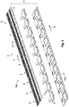
- FIG. 1 illustrates a connection arrangement 1 according to the invention.
- the connection arrangement 1 comprises cell contacts 2 which are connected to voltage sources which are located here in a state hidden under covers 3.
- the voltage sources simultaneously act as voltage sinks so that, in accordance with requirements, electrical power can be drawn or supplied and, for instance, stored.
- Each of the cell contacts 2 is connected to a cell connection line 4.
- the cell connection lines 4 are portions of a ribbon-like connector 5.
- the cell connection lines 4 are embedded in the ribbon-like connector 5 and extend beside each other, in particular in a parallel manner along the extent direction 6 of the ribbon-like connector 5.
- the ribbon-like connector 5 has at the upper side 7 thereof welding openings 8 which are aligned with welding openings 8 fitted at the lower side of the ribbon-like connector 5.
- the cell connection lines 4 of the ribbon-like connector 5 which are exposed have been welded to the cell contacts 2. Since the cell contacts 2 and the cell contact line 4 comprise the same material, for instance, in the example shown, aluminium, encapsulation of the connection is unnecessary because there is not present between the two any electrochemical voltage which could result in corrosion between the two. Alternatively, for instance, copper could be used as the material for the cell connection line 4 and the cell contacts 2.
- the ribbon-like connector 5 is produced in this instance by a flat ribbon line 9, a so-called FFC (Flat Flex Cable). It comprises an insulating outer member 30, for example, comprising plastics material, in which the cell connection lines 4 are embedded.
- the ribbon-like connector 5 may be bonded to the cell contacts 2 and/or the covers 3, for example, by melting an adhesive or the material of the outer member 30.
- the cell contacts 2 and the cell connection lines 4 are fixed in a ribbon-like retention member 9.
- the ribbon-like retention member 9 has a connection region 10 at one end 11, at which the cell connection lines 4 and connection lines 12 are connected.
- the connection lines 12 serve to connect the cell connection lines 4 to an external electrical component 13, in this instance in the form of a plug 14.
- the connection lines 12 are surrounded by an insulation 15, with which they form a cable.
- connection region 11 between the cell connection lines 4 and the connection lines 12 is encapsulated by a casting compound 16.
- the casting compound 16 encapsulates all the connection regions between a cell connection line 4 and a connection line 12 at the same time.
- the casting compound 16 is in this instance a low-pressure casting compound which has been applied in an injection-moulding step, for example, by overmoulding.
- the casting compound 16 has been fixed to a base member 17. It is connected to the base member 17 in a mechanically stable manner and consequently forms a tension relief member 18 for the cell connection line 4. Tensile forces from the region of the plug 14 and the connection line 12 are taken up by the tension relief member 18 and directed into the base member 17 so that the cell connection lines 4 are not subjected to any mechanical loads.
- connection lines 4 are connected in the connection region 11 to the connection lines 12 in an electrically conductive manner by means of a crimping. That crimping is embedded in the casting compound 16, whereby the connection region 11 is encapsulated and protected from environmental influences.
- connection region 11 may be covered by a covering layer, for instance, by an impressed covering layer or a covering layer comprising a rapidly hardening dispersion adhesive.
- the material of the covering layer may comprise a material which hardens alone or by means of external influences, for instance, by UV irradiation.
- the covering layer may comprise, for example, two materials which only harden when they are in contact with each other.
- a casting compound 16 may also comprise the materials mentioned.
- connection lines 12 may comprise a different material from that of the cell connection lines 4.
- the cell connection lines 4 may comprise aluminium and the connection lines 12 may comprise copper.
- the connection produced in this manner is not at risk of corrosion.
- connection lines 12 may also comprise the same material as the cell connection lines 4 and the cell contacts 2, that is to say, in this instance also aluminium.
- encapsulation of the connection region 11 between the cell connection lines 4 and the connection lines 12 would not be absolutely necessary because there is also then no electrochemical potential between the two in this instance.
- a change to another material, for example, to copper, could then be brought about in the region of the plug 14.
- FIG. 2 is an exploded view of a portion of another connection arrangement 1 according to the invention.
- a plurality of cell contacts 2 which are arranged one behind the other in an extent direction 6 of a ribbon-like connector 5.
- the cell connection lines 4 are in a state embedded as thin wires in the ribbon-like connector 5 and are connected to a cell contact 2 in the region of a welding opening 8, respectively.
- the cell contacts 2 and the cell connection lines 4 are secured in a ribbon-like retention member 9. What is not shown in this instance, at one end of the ribbon-like retention member 9, is a connection region in which the cell connection lines 4 are connected to connection lines.
- the ribbon-like retention member 9 has a lower portion 19a comprising a deep-drawn plastics plate and an upper portion 19b which is in the form of a flat ribbon line in this instance.
- the cell contacts 2 are embedded between the lower portion 19a and the upper portion 19b.
- Voltage sources for example, galvanic cells
- the cell contacts 2 shown here can be contacted at a total of four locations from below per cell contact 2. Two locations are used to contact an electrode of a galvanic cell, respectively.
- the cell contacts 2 are in the form of cell connectors 21 which connect two galvanic cells to each other.
- the anode of a first galvanic cell can be bridged with the cathode of a second galvanic cell by a cell contact 2.
- a second cell contact 2 can again connect the anode of the second galvanic cell to the cathode of a third galvanic cell, etc.
- Voltage is built up as a result of this serial connection of the galvanic cells.
- a parallel connection could also be brought about, for example, in order to be able to draw a high current.
- a cell connection line 4 is used to tap a control voltage at the cell contacts 2. The function and the charging state of the individual galvanic cells can thereby be monitored constantly.
- a cell contact 2 can also be constructed in such a manner that it is simultaneously an electrode of the galvanic cell. It is thereby possible to save an element, whereby the production costs are reduced.
- Figure 3 illustrates by way of example a use of a connection arrangement 1 according to the invention.
- the connection arrangement 1 is only partially shown.
- Figure 3 shows a traction battery 27, in which a large number of voltage sources and voltage sinks 25 in the form of galvanic cells 26 are connected to each other.
- the voltage sources and voltage sinks 25 are arranged in a row one behind the other, a voltage source and voltage sink 25 being rotated through 180° relative to the adjacent voltage sources and sinks so that an anode 28 is located between two cathodes 29, respectively.
- An anode 28 and a cathode 29 of two different galvanic cells 26 are connected to each other via the cell contacts 2.
- the cell connection lines 4 are connected to the cell contacts 2.
- the cell connection lines 4 extend parallel with each other along an extent direction 6 of a ribbon-like connector 5 and lead to the edge of the traction battery 27.
- Another connector 5 (not illustrated here) connects the electrodes which are illustrated at the top in Figure 3 . That second connector 5 is offset relative to the first connector 5 by a cell so that overall the current path extends substantially in a zig-zag manner.
- the cell contacts 2 are connected only to a single electrode of a galvanic cell 26. The total voltage can then be tapped at those cell contacts 2.
- the Figures show by way of example galvanic cells 26 as voltage sources and sinks 25 in the form of cells.
- voltage sources and/or sinks 25 in the form of cells may also be used, for example, capacitors, in particular super-capacitors ("Supercaps").
- Supercaps super-capacitors
Landscapes
- Chemical & Material Sciences (AREA)
- Chemical Kinetics & Catalysis (AREA)
- Electrochemistry (AREA)
- General Chemical & Material Sciences (AREA)
- Engineering & Computer Science (AREA)
- Manufacturing & Machinery (AREA)
- Inorganic Chemistry (AREA)
- Connection Of Batteries Or Terminals (AREA)
- Electric Double-Layer Capacitors Or The Like (AREA)
- Connections Effected By Soldering, Adhesion, Or Permanent Deformation (AREA)
Claims (13)
- Verbindungsanordnung (1) zum Verbinden wenigstens einer Spannungsquelle und/oder Spannungssenke (25), die die Form einer Zelle einer Traktionsbatterie (27) hat, mit einem externen elektrischen Bauteil (13), umfassend einen Zellenkontakt (2) zum Kontaktieren der Spannungsquelle und/oder -senke (25), eine an den Zellenkontakt (2) angeschlossene Zellenanschlussleitung (4) und eine an deren vom Zellenkontakt (2) abgewandten Ende an die Zellenanschlussleitung (4) angeschlossene Verbindungsleitung (12) zur Verbindung mit dem externen elektrischen Bauelement (13), wobei die Zellenanschlussleitung (4) das gleiche Material umfasst wie der Zellenkontakt (2), dadurch gekennzeichnet, dass eine Vergussmasse (16) um einen Verbindungsbereich (11) herum eingebracht ist, an dem die Verbindungsleitung (12) mit der Zellenanschlussleitung (4) verbunden ist, wobei die Zellenanschlussleitung (4) über die Vergussmasse (16) an einem Grundkörper (17) der Traktionsbatterie (27) befestigt ist.
- Verbindungsanordnung (1) nach Anspruch 1, wobei die Zellenanschlussleitung (4) und die Verbindungsleitung (12) durch Crimpen elektrisch leitend miteinander verbunden sind.
- Verbindungsanordnung (1) nach Anspruch 1 oder 2, wobei der Zellenkontakt (2) und die Zellenanschlussleitung (4) in einem bandförmigen Haltekörper (9) befestigt sind, und wobei der Haltekörper (9) einen Verbindungsbereich (11) an einem Ende (10) aufweist, an dem die Zellenanschlussleitung (4) und die Verbindungsleitung (12) miteinander verbunden sind.
- Verbindungsanordnung (1) nach einem der Ansprüche 1 bis 3, wobei ein Verbindungsbereich (11), an dem die Verbindungsleitung (12) mit der Zellenanschlussleitung (4) verbunden ist, gekapselt ist.
- Verbindungsanordnung (1) nach einem der Ansprüche 1 bis 4, wobei ein Verbindungsbereich (11), an dem die Verbindungsleitung (12) mit der Zellenanschlussleitung (4) verbunden ist, eine Schutzschicht aufweist.
- Verbindungsanordnung (1) nach einem der Ansprüche 1 bis 5, wobei der Zellenkontakt (2) an die Zellenanschlussleitung (4) angeschweißt ist.
- Verbindungsanordnung (1) nach einem der Ansprüche 1 bis 6, wobei die Zellenanschlussleitung (4) Aluminium enthält.
- Verbindungsanordnung (1) nach einem der Ansprüche 1 bis 7, wobei die Zellenanschlussleitung (4) ein Teil eines bandförmigen Verbinders (5) ist.
- Verbindungsanordnung (1) nach einem der Ansprüche 1 bis 8, wobei die Verbindungsanordnung (1) mehrere Zellenanschlussleitungen (4) umfasst, die nebeneinander in einem einzigen bandförmigen Verbinder (5) angeordnet sind.
- Verbindungsanordnung (1) nach einem der Ansprüche 1 bis 9, wobei die Verbindungsleitung (12) das gleiche Material umfasst wie der Zellenkontakt (2).
- Elektrische Anordnung, die eine Spannungsquelle und/oder -senke (25) sowie eine Verbindungsanordnung (1) nach einem der Ansprüche 1 bis 10 umfasst.
- Elektrische Anordnung nach Anspruch 11, wobei die Spannungsquelle und/oder die Spannungssenke (25) eine galvanische Zelle (26) sind/ist.
- Elektrische Anordnung nach Anspruch 12, wobei der Zellenkontakt (2) eine Elektrode der galvanischen Zelle (26) ist.
Applications Claiming Priority (2)
| Application Number | Priority Date | Filing Date | Title |
|---|---|---|---|
| DE102013221870.2A DE102013221870B4 (de) | 2013-10-28 | 2013-10-28 | Verbindungsanordnung zur Verbindung mindestens einer als Zelle ausgestalteten Spannungsquelle und/oder -senke mit einem externen elektrischen Bauelement und elektrische Anordnung umfassend eine Verbindungsanordnung |
| PCT/EP2014/073019 WO2015063035A1 (en) | 2013-10-28 | 2014-10-27 | Connection arrangement for connecting at least one voltage source and/or voltage sink which is in the form of a cell to an external electrical component and electrical arrangement comprising a connection arrangement |
Publications (2)
| Publication Number | Publication Date |
|---|---|
| EP3063835A1 EP3063835A1 (de) | 2016-09-07 |
| EP3063835B1 true EP3063835B1 (de) | 2019-11-27 |
Family
ID=51794893
Family Applications (1)
| Application Number | Title | Priority Date | Filing Date |
|---|---|---|---|
| EP14789307.7A Active EP3063835B1 (de) | 2013-10-28 | 2014-10-27 | Verbindungsanordnung zum verbinden von wenigstens einer spannungsquelle und/oder spannungssenke in form einer zelle einer traktionsbatterie an eine externe elektrische komponente und elektrische anordnung mit einer verbindungsanordnung |
Country Status (7)
| Country | Link |
|---|---|
| US (1) | US11201377B2 (de) |
| EP (1) | EP3063835B1 (de) |
| JP (1) | JP6640080B2 (de) |
| KR (1) | KR102327042B1 (de) |
| CN (1) | CN105659440B (de) |
| DE (1) | DE102013221870B4 (de) |
| WO (1) | WO2015063035A1 (de) |
Cited By (1)
| Publication number | Priority date | Publication date | Assignee | Title |
|---|---|---|---|---|
| TWI754413B (zh) * | 2020-07-03 | 2022-02-01 | 美商莫仕有限公司 | 電池連接模組 |
Families Citing this family (6)
| Publication number | Priority date | Publication date | Assignee | Title |
|---|---|---|---|---|
| DE102015209945A1 (de) * | 2015-05-29 | 2016-12-01 | Robert Bosch Gmbh | Leiterelement einer Kontaktierungsanordnung einer Batteriezelle, Kontaktierungsanordnung einer Batteriezelle mit einem solchen Leiterelement, Verfahren zu deren Herstellung, Batteriezelle und Batterie |
| PL3425970T3 (pl) | 2016-06-21 | 2021-12-13 | Guangdong Oppo Mobile Telecommunications Corp., Ltd. | Wysyłanie informacji o wskazaniu kanału nadawania |
| JP6581959B2 (ja) * | 2016-12-19 | 2019-09-25 | 矢崎総業株式会社 | 端子用導体モジュール |
| CN109428183B (zh) * | 2017-08-24 | 2020-10-30 | 莫列斯有限公司 | 电池连接模块 |
| DE102019208769A1 (de) * | 2019-06-17 | 2020-12-17 | Mahle International Gmbh | Akkumulator |
| CN116746286A (zh) * | 2021-11-25 | 2023-09-12 | 微软技术许可有限责任公司 | 电缆连接器 |
Citations (1)
| Publication number | Priority date | Publication date | Assignee | Title |
|---|---|---|---|---|
| US5770818A (en) * | 1995-04-25 | 1998-06-23 | Yazaki Corporation | Connector for establishing connection between electric wires and flat cable and manufacturing method thereof |
Family Cites Families (27)
| Publication number | Priority date | Publication date | Assignee | Title |
|---|---|---|---|---|
| DE2142768B2 (de) | 1971-08-26 | 1979-05-03 | Varta Batterie Ag, 3000 Hannover | Batterie aus mehreren miteinander verbundenen Bleiakkumulatorenzellen |
| JPH0236710A (ja) * | 1988-04-12 | 1990-02-06 | Sumitomo Electric Ind Ltd | 平型電線とリード線の接続方法 |
| US5007280A (en) | 1990-01-26 | 1991-04-16 | Molex Incorporated | Tool head for use in crimping electrical connectors |
| JP3343888B2 (ja) * | 1997-10-13 | 2002-11-11 | トヨタ自動車株式会社 | バッテリーホルダ用接続プレートおよびその製造方法 |
| JP3343889B2 (ja) | 1997-10-13 | 2002-11-11 | トヨタ自動車株式会社 | バッテリーホルダ用接続プレート |
| JP3707595B2 (ja) * | 1998-09-09 | 2005-10-19 | 矢崎総業株式会社 | バッテリ接続プレート |
| JP2001102712A (ja) * | 1999-10-01 | 2001-04-13 | Rohm Co Ltd | コネクタ付きの配線基板、およびその製造方法 |
| JP4182854B2 (ja) * | 2003-10-10 | 2008-11-19 | 日産自動車株式会社 | 電池電極の溶接方法、および組電池 |
| JP2005222701A (ja) | 2004-02-03 | 2005-08-18 | Shin Kobe Electric Mach Co Ltd | 組電池 |
| JP2006245453A (ja) | 2005-03-07 | 2006-09-14 | Three M Innovative Properties Co | フレキシブルプリント回路基板の他の回路基板への接続方法 |
| US8342459B2 (en) * | 2008-03-06 | 2013-01-01 | Covidien Lp | Wire organizer |
| WO2010113455A1 (ja) * | 2009-03-31 | 2010-10-07 | 三洋電機株式会社 | 電池モジュール、バッテリシステムおよび電動車両 |
| JP2011049155A (ja) * | 2009-07-30 | 2011-03-10 | Sanyo Electric Co Ltd | バッテリシステムおよびそれを備えた電動車両 |
| JPWO2011024477A1 (ja) | 2009-08-31 | 2013-01-24 | 三洋電機株式会社 | バッテリモジュール、バッテリシステムおよび電動車両 |
| CN102668165B (zh) | 2009-10-01 | 2015-01-14 | 迪尔基金两合公司 | 借助于电池连接器电联接电池组的电池的装置和具有这种电池连接器的电池组 |
| US8928673B2 (en) * | 2010-06-30 | 2015-01-06 | Blue Sky Studios, Inc. | Methods and systems for 3D animation |
| WO2012026093A1 (ja) * | 2010-08-25 | 2012-03-01 | 三洋電機株式会社 | バッテリモジュール、バッテリシステム、電動車両、移動体、電力貯蔵装置および電源装置 |
| KR101441423B1 (ko) * | 2010-09-01 | 2014-10-20 | 에스케이이노베이션 주식회사 | 일체형 전지 연결 장치가 구비되는 고전압 배터리 |
| JP5880930B2 (ja) * | 2011-01-28 | 2016-03-09 | 株式会社オートネットワーク技術研究所 | 電池接続アセンブリ |
| JP2012227002A (ja) * | 2011-04-20 | 2012-11-15 | Auto Network Gijutsu Kenkyusho:Kk | 配線モジュール |
| JP2013016381A (ja) * | 2011-07-05 | 2013-01-24 | Auto Network Gijutsu Kenkyusho:Kk | 電池配線モジュール |
| DE102011056718B4 (de) | 2011-12-20 | 2024-02-15 | Bmz Germany Gmbh | Elektrisches Bauteil |
| JP2013152918A (ja) * | 2011-12-26 | 2013-08-08 | Auto Network Gijutsu Kenkyusho:Kk | 配線モジュール |
| DE102012205019A1 (de) | 2012-03-28 | 2013-10-02 | Elringklinger Ag | Zellkontaktierungssystem für eine elektrochemische Vorrichtung und Verfahren zum Herstellen eines Zellkontaktierungssystems |
| DE102012205910A1 (de) | 2012-04-11 | 2013-10-17 | Elringklinger Ag | Zellkontaktierungssystem für eine elektrochemische Vorrichtung und Verfahren zum Herstellen eines Zellkontaktierungssystems |
| JP6033019B2 (ja) * | 2012-09-19 | 2016-11-30 | 矢崎総業株式会社 | バスバーと電線の接続構造 |
| US9660357B1 (en) | 2016-03-22 | 2017-05-23 | David Worsham | Electrical connector with internal crimping mechanism |
-
2013
- 2013-10-28 DE DE102013221870.2A patent/DE102013221870B4/de not_active Expired - Fee Related
-
2014
- 2014-10-27 EP EP14789307.7A patent/EP3063835B1/de active Active
- 2014-10-27 WO PCT/EP2014/073019 patent/WO2015063035A1/en not_active Ceased
- 2014-10-27 JP JP2016526091A patent/JP6640080B2/ja active Active
- 2014-10-27 CN CN201480058643.XA patent/CN105659440B/zh active Active
- 2014-10-27 KR KR1020167013919A patent/KR102327042B1/ko active Active
-
2016
- 2016-04-28 US US15/140,668 patent/US11201377B2/en active Active
Patent Citations (1)
| Publication number | Priority date | Publication date | Assignee | Title |
|---|---|---|---|---|
| US5770818A (en) * | 1995-04-25 | 1998-06-23 | Yazaki Corporation | Connector for establishing connection between electric wires and flat cable and manufacturing method thereof |
Cited By (1)
| Publication number | Priority date | Publication date | Assignee | Title |
|---|---|---|---|---|
| TWI754413B (zh) * | 2020-07-03 | 2022-02-01 | 美商莫仕有限公司 | 電池連接模組 |
Also Published As
| Publication number | Publication date |
|---|---|
| JP2017503306A (ja) | 2017-01-26 |
| US20160240832A1 (en) | 2016-08-18 |
| KR20160077146A (ko) | 2016-07-01 |
| WO2015063035A1 (en) | 2015-05-07 |
| KR102327042B1 (ko) | 2021-11-15 |
| DE102013221870A1 (de) | 2015-04-30 |
| EP3063835A1 (de) | 2016-09-07 |
| JP6640080B2 (ja) | 2020-02-05 |
| DE102013221870B4 (de) | 2021-09-30 |
| CN105659440A (zh) | 2016-06-08 |
| CN105659440B (zh) | 2019-06-18 |
| US11201377B2 (en) | 2021-12-14 |
Similar Documents
| Publication | Publication Date | Title |
|---|---|---|
| EP3063835B1 (de) | Verbindungsanordnung zum verbinden von wenigstens einer spannungsquelle und/oder spannungssenke in form einer zelle einer traktionsbatterie an eine externe elektrische komponente und elektrische anordnung mit einer verbindungsanordnung | |
| EP3123539B1 (de) | Verbinder zur verbindung elektrischer zellenelemente und verfahren zur installation solch eines verbinders an eine batterieeinheit | |
| EP3686956B1 (de) | Batteriemodul mit stromschiene und batteriesatz | |
| CN109390537B (zh) | 导体模块 | |
| JP6033019B2 (ja) | バスバーと電線の接続構造 | |
| US9960401B2 (en) | Wiring module | |
| US8721367B2 (en) | Fuse unit | |
| EP3314678B1 (de) | Deckelanordnung für batteriemodul | |
| JP6717788B2 (ja) | 導体モジュール | |
| EP3579306B1 (de) | Batteriemodul | |
| JP5825991B2 (ja) | 蓄電池用の電線配索構造 | |
| JP2015517728A (ja) | バイメタルバスバーアセンブリ | |
| EP4167252B1 (de) | Folienkabel umfassend eine sicherungssleitung | |
| EP3641045B1 (de) | Kabelartige batterie | |
| US20140308561A1 (en) | Current tap element for an energy storage module | |
| EP3358644B1 (de) | Batteriezelle und batteriemodul | |
| US20130196217A1 (en) | Battery, Battery System and Method for Connecting a Plurality of Batteries | |
| KR101973055B1 (ko) | 회로보호모듈 일체형 캡 조립체, 캡 조립체의 제조 방법, 및 이차 전지 |
Legal Events
| Date | Code | Title | Description |
|---|---|---|---|
| PUAI | Public reference made under article 153(3) epc to a published international application that has entered the european phase |
Free format text: ORIGINAL CODE: 0009012 |
|
| 17P | Request for examination filed |
Effective date: 20160524 |
|
| AK | Designated contracting states |
Kind code of ref document: A1 Designated state(s): AL AT BE BG CH CY CZ DE DK EE ES FI FR GB GR HR HU IE IS IT LI LT LU LV MC MK MT NL NO PL PT RO RS SE SI SK SM TR |
|
| AX | Request for extension of the european patent |
Extension state: BA ME |
|
| DAX | Request for extension of the european patent (deleted) | ||
| STAA | Information on the status of an ep patent application or granted ep patent |
Free format text: STATUS: EXAMINATION IS IN PROGRESS |
|
| 17Q | First examination report despatched |
Effective date: 20171211 |
|
| GRAP | Despatch of communication of intention to grant a patent |
Free format text: ORIGINAL CODE: EPIDOSNIGR1 |
|
| STAA | Information on the status of an ep patent application or granted ep patent |
Free format text: STATUS: GRANT OF PATENT IS INTENDED |
|
| INTG | Intention to grant announced |
Effective date: 20190628 |
|
| GRAS | Grant fee paid |
Free format text: ORIGINAL CODE: EPIDOSNIGR3 |
|
| GRAA | (expected) grant |
Free format text: ORIGINAL CODE: 0009210 |
|
| STAA | Information on the status of an ep patent application or granted ep patent |
Free format text: STATUS: THE PATENT HAS BEEN GRANTED |
|
| AK | Designated contracting states |
Kind code of ref document: B1 Designated state(s): AL AT BE BG CH CY CZ DE DK EE ES FI FR GB GR HR HU IE IS IT LI LT LU LV MC MK MT NL NO PL PT RO RS SE SI SK SM TR |
|
| REG | Reference to a national code |
Ref country code: GB Ref legal event code: FG4D |
|
| REG | Reference to a national code |
Ref country code: CH Ref legal event code: EP |
|
| REG | Reference to a national code |
Ref country code: AT Ref legal event code: REF Ref document number: 1207772 Country of ref document: AT Kind code of ref document: T Effective date: 20191215 |
|
| REG | Reference to a national code |
Ref country code: DE Ref legal event code: R096 Ref document number: 602014057547 Country of ref document: DE |
|
| REG | Reference to a national code |
Ref country code: IE Ref legal event code: FG4D |
|
| REG | Reference to a national code |
Ref country code: NL Ref legal event code: MP Effective date: 20191127 |
|
| REG | Reference to a national code |
Ref country code: LT Ref legal event code: MG4D |
|
| PG25 | Lapsed in a contracting state [announced via postgrant information from national office to epo] |
Ref country code: NO Free format text: LAPSE BECAUSE OF FAILURE TO SUBMIT A TRANSLATION OF THE DESCRIPTION OR TO PAY THE FEE WITHIN THE PRESCRIBED TIME-LIMIT Effective date: 20200227 Ref country code: GR Free format text: LAPSE BECAUSE OF FAILURE TO SUBMIT A TRANSLATION OF THE DESCRIPTION OR TO PAY THE FEE WITHIN THE PRESCRIBED TIME-LIMIT Effective date: 20200228 Ref country code: BG Free format text: LAPSE BECAUSE OF FAILURE TO SUBMIT A TRANSLATION OF THE DESCRIPTION OR TO PAY THE FEE WITHIN THE PRESCRIBED TIME-LIMIT Effective date: 20200227 Ref country code: FI Free format text: LAPSE BECAUSE OF FAILURE TO SUBMIT A TRANSLATION OF THE DESCRIPTION OR TO PAY THE FEE WITHIN THE PRESCRIBED TIME-LIMIT Effective date: 20191127 Ref country code: LT Free format text: LAPSE BECAUSE OF FAILURE TO SUBMIT A TRANSLATION OF THE DESCRIPTION OR TO PAY THE FEE WITHIN THE PRESCRIBED TIME-LIMIT Effective date: 20191127 Ref country code: LV Free format text: LAPSE BECAUSE OF FAILURE TO SUBMIT A TRANSLATION OF THE DESCRIPTION OR TO PAY THE FEE WITHIN THE PRESCRIBED TIME-LIMIT Effective date: 20191127 Ref country code: SE Free format text: LAPSE BECAUSE OF FAILURE TO SUBMIT A TRANSLATION OF THE DESCRIPTION OR TO PAY THE FEE WITHIN THE PRESCRIBED TIME-LIMIT Effective date: 20191127 Ref country code: NL Free format text: LAPSE BECAUSE OF FAILURE TO SUBMIT A TRANSLATION OF THE DESCRIPTION OR TO PAY THE FEE WITHIN THE PRESCRIBED TIME-LIMIT Effective date: 20191127 |
|
| PG25 | Lapsed in a contracting state [announced via postgrant information from national office to epo] |
Ref country code: IS Free format text: LAPSE BECAUSE OF FAILURE TO SUBMIT A TRANSLATION OF THE DESCRIPTION OR TO PAY THE FEE WITHIN THE PRESCRIBED TIME-LIMIT Effective date: 20200327 Ref country code: HR Free format text: LAPSE BECAUSE OF FAILURE TO SUBMIT A TRANSLATION OF THE DESCRIPTION OR TO PAY THE FEE WITHIN THE PRESCRIBED TIME-LIMIT Effective date: 20191127 Ref country code: RS Free format text: LAPSE BECAUSE OF FAILURE TO SUBMIT A TRANSLATION OF THE DESCRIPTION OR TO PAY THE FEE WITHIN THE PRESCRIBED TIME-LIMIT Effective date: 20191127 |
|
| PG25 | Lapsed in a contracting state [announced via postgrant information from national office to epo] |
Ref country code: AL Free format text: LAPSE BECAUSE OF FAILURE TO SUBMIT A TRANSLATION OF THE DESCRIPTION OR TO PAY THE FEE WITHIN THE PRESCRIBED TIME-LIMIT Effective date: 20191127 |
|
| PG25 | Lapsed in a contracting state [announced via postgrant information from national office to epo] |
Ref country code: ES Free format text: LAPSE BECAUSE OF FAILURE TO SUBMIT A TRANSLATION OF THE DESCRIPTION OR TO PAY THE FEE WITHIN THE PRESCRIBED TIME-LIMIT Effective date: 20191127 Ref country code: DK Free format text: LAPSE BECAUSE OF FAILURE TO SUBMIT A TRANSLATION OF THE DESCRIPTION OR TO PAY THE FEE WITHIN THE PRESCRIBED TIME-LIMIT Effective date: 20191127 Ref country code: PT Free format text: LAPSE BECAUSE OF FAILURE TO SUBMIT A TRANSLATION OF THE DESCRIPTION OR TO PAY THE FEE WITHIN THE PRESCRIBED TIME-LIMIT Effective date: 20200419 Ref country code: EE Free format text: LAPSE BECAUSE OF FAILURE TO SUBMIT A TRANSLATION OF THE DESCRIPTION OR TO PAY THE FEE WITHIN THE PRESCRIBED TIME-LIMIT Effective date: 20191127 Ref country code: RO Free format text: LAPSE BECAUSE OF FAILURE TO SUBMIT A TRANSLATION OF THE DESCRIPTION OR TO PAY THE FEE WITHIN THE PRESCRIBED TIME-LIMIT Effective date: 20191127 Ref country code: CZ Free format text: LAPSE BECAUSE OF FAILURE TO SUBMIT A TRANSLATION OF THE DESCRIPTION OR TO PAY THE FEE WITHIN THE PRESCRIBED TIME-LIMIT Effective date: 20191127 |
|
| REG | Reference to a national code |
Ref country code: DE Ref legal event code: R097 Ref document number: 602014057547 Country of ref document: DE |
|
| PG25 | Lapsed in a contracting state [announced via postgrant information from national office to epo] |
Ref country code: SM Free format text: LAPSE BECAUSE OF FAILURE TO SUBMIT A TRANSLATION OF THE DESCRIPTION OR TO PAY THE FEE WITHIN THE PRESCRIBED TIME-LIMIT Effective date: 20191127 Ref country code: SK Free format text: LAPSE BECAUSE OF FAILURE TO SUBMIT A TRANSLATION OF THE DESCRIPTION OR TO PAY THE FEE WITHIN THE PRESCRIBED TIME-LIMIT Effective date: 20191127 |
|
| REG | Reference to a national code |
Ref country code: AT Ref legal event code: MK05 Ref document number: 1207772 Country of ref document: AT Kind code of ref document: T Effective date: 20191127 |
|
| PLBE | No opposition filed within time limit |
Free format text: ORIGINAL CODE: 0009261 |
|
| STAA | Information on the status of an ep patent application or granted ep patent |
Free format text: STATUS: NO OPPOSITION FILED WITHIN TIME LIMIT |
|
| 26N | No opposition filed |
Effective date: 20200828 |
|
| PG25 | Lapsed in a contracting state [announced via postgrant information from national office to epo] |
Ref country code: PL Free format text: LAPSE BECAUSE OF FAILURE TO SUBMIT A TRANSLATION OF THE DESCRIPTION OR TO PAY THE FEE WITHIN THE PRESCRIBED TIME-LIMIT Effective date: 20191127 Ref country code: AT Free format text: LAPSE BECAUSE OF FAILURE TO SUBMIT A TRANSLATION OF THE DESCRIPTION OR TO PAY THE FEE WITHIN THE PRESCRIBED TIME-LIMIT Effective date: 20191127 Ref country code: SI Free format text: LAPSE BECAUSE OF FAILURE TO SUBMIT A TRANSLATION OF THE DESCRIPTION OR TO PAY THE FEE WITHIN THE PRESCRIBED TIME-LIMIT Effective date: 20191127 |
|
| PG25 | Lapsed in a contracting state [announced via postgrant information from national office to epo] |
Ref country code: IT Free format text: LAPSE BECAUSE OF FAILURE TO SUBMIT A TRANSLATION OF THE DESCRIPTION OR TO PAY THE FEE WITHIN THE PRESCRIBED TIME-LIMIT Effective date: 20191127 |
|
| REG | Reference to a national code |
Ref country code: CH Ref legal event code: PL |
|
| GBPC | Gb: european patent ceased through non-payment of renewal fee |
Effective date: 20201027 |
|
| PG25 | Lapsed in a contracting state [announced via postgrant information from national office to epo] |
Ref country code: LU Free format text: LAPSE BECAUSE OF NON-PAYMENT OF DUE FEES Effective date: 20201027 Ref country code: MC Free format text: LAPSE BECAUSE OF FAILURE TO SUBMIT A TRANSLATION OF THE DESCRIPTION OR TO PAY THE FEE WITHIN THE PRESCRIBED TIME-LIMIT Effective date: 20191127 |
|
| REG | Reference to a national code |
Ref country code: BE Ref legal event code: MM Effective date: 20201031 |
|
| PG25 | Lapsed in a contracting state [announced via postgrant information from national office to epo] |
Ref country code: FR Free format text: LAPSE BECAUSE OF NON-PAYMENT OF DUE FEES Effective date: 20201031 |
|
| PG25 | Lapsed in a contracting state [announced via postgrant information from national office to epo] |
Ref country code: CH Free format text: LAPSE BECAUSE OF NON-PAYMENT OF DUE FEES Effective date: 20201031 Ref country code: BE Free format text: LAPSE BECAUSE OF NON-PAYMENT OF DUE FEES Effective date: 20201031 Ref country code: LI Free format text: LAPSE BECAUSE OF NON-PAYMENT OF DUE FEES Effective date: 20201031 Ref country code: GB Free format text: LAPSE BECAUSE OF NON-PAYMENT OF DUE FEES Effective date: 20201027 |
|
| PG25 | Lapsed in a contracting state [announced via postgrant information from national office to epo] |
Ref country code: IE Free format text: LAPSE BECAUSE OF NON-PAYMENT OF DUE FEES Effective date: 20201027 |
|
| PG25 | Lapsed in a contracting state [announced via postgrant information from national office to epo] |
Ref country code: TR Free format text: LAPSE BECAUSE OF FAILURE TO SUBMIT A TRANSLATION OF THE DESCRIPTION OR TO PAY THE FEE WITHIN THE PRESCRIBED TIME-LIMIT Effective date: 20191127 Ref country code: MT Free format text: LAPSE BECAUSE OF FAILURE TO SUBMIT A TRANSLATION OF THE DESCRIPTION OR TO PAY THE FEE WITHIN THE PRESCRIBED TIME-LIMIT Effective date: 20191127 Ref country code: CY Free format text: LAPSE BECAUSE OF FAILURE TO SUBMIT A TRANSLATION OF THE DESCRIPTION OR TO PAY THE FEE WITHIN THE PRESCRIBED TIME-LIMIT Effective date: 20191127 |
|
| PG25 | Lapsed in a contracting state [announced via postgrant information from national office to epo] |
Ref country code: MK Free format text: LAPSE BECAUSE OF FAILURE TO SUBMIT A TRANSLATION OF THE DESCRIPTION OR TO PAY THE FEE WITHIN THE PRESCRIBED TIME-LIMIT Effective date: 20191127 |
|
| PGFP | Annual fee paid to national office [announced via postgrant information from national office to epo] |
Ref country code: DE Payment date: 20250902 Year of fee payment: 12 |