EP3061994B1 - Control device for continuously variable transmission - Google Patents
Control device for continuously variable transmission Download PDFInfo
- Publication number
- EP3061994B1 EP3061994B1 EP14855144.3A EP14855144A EP3061994B1 EP 3061994 B1 EP3061994 B1 EP 3061994B1 EP 14855144 A EP14855144 A EP 14855144A EP 3061994 B1 EP3061994 B1 EP 3061994B1
- Authority
- EP
- European Patent Office
- Prior art keywords
- pressure
- control
- control mode
- selection
- selection control
- Prior art date
- Legal status (The legal status is an assumption and is not a legal conclusion. Google has not performed a legal analysis and makes no representation as to the accuracy of the status listed.)
- Not-in-force
Links
Images


Classifications
-
- F—MECHANICAL ENGINEERING; LIGHTING; HEATING; WEAPONS; BLASTING
- F16—ENGINEERING ELEMENTS AND UNITS; GENERAL MEASURES FOR PRODUCING AND MAINTAINING EFFECTIVE FUNCTIONING OF MACHINES OR INSTALLATIONS; THERMAL INSULATION IN GENERAL
- F16H—GEARING
- F16H61/00—Control functions within control units of change-speed- or reversing-gearings for conveying rotary motion ; Control of exclusively fluid gearing, friction gearing, gearings with endless flexible members or other particular types of gearing
- F16H61/66—Control functions within control units of change-speed- or reversing-gearings for conveying rotary motion ; Control of exclusively fluid gearing, friction gearing, gearings with endless flexible members or other particular types of gearing specially adapted for continuously variable gearings
- F16H61/662—Control functions within control units of change-speed- or reversing-gearings for conveying rotary motion ; Control of exclusively fluid gearing, friction gearing, gearings with endless flexible members or other particular types of gearing specially adapted for continuously variable gearings with endless flexible members
- F16H61/66272—Control functions within control units of change-speed- or reversing-gearings for conveying rotary motion ; Control of exclusively fluid gearing, friction gearing, gearings with endless flexible members or other particular types of gearing specially adapted for continuously variable gearings with endless flexible members characterised by means for controlling the torque transmitting capability of the gearing
-
- F—MECHANICAL ENGINEERING; LIGHTING; HEATING; WEAPONS; BLASTING
- F16—ENGINEERING ELEMENTS AND UNITS; GENERAL MEASURES FOR PRODUCING AND MAINTAINING EFFECTIVE FUNCTIONING OF MACHINES OR INSTALLATIONS; THERMAL INSULATION IN GENERAL
- F16H—GEARING
- F16H61/00—Control functions within control units of change-speed- or reversing-gearings for conveying rotary motion ; Control of exclusively fluid gearing, friction gearing, gearings with endless flexible members or other particular types of gearing
- F16H61/66—Control functions within control units of change-speed- or reversing-gearings for conveying rotary motion ; Control of exclusively fluid gearing, friction gearing, gearings with endless flexible members or other particular types of gearing specially adapted for continuously variable gearings
- F16H61/664—Friction gearings
- F16H61/6649—Friction gearings characterised by the means for controlling the torque transmitting capability of the gearing
-
- F—MECHANICAL ENGINEERING; LIGHTING; HEATING; WEAPONS; BLASTING
- F16—ENGINEERING ELEMENTS AND UNITS; GENERAL MEASURES FOR PRODUCING AND MAINTAINING EFFECTIVE FUNCTIONING OF MACHINES OR INSTALLATIONS; THERMAL INSULATION IN GENERAL
- F16H—GEARING
- F16H9/00—Gearings for conveying rotary motion with variable gear ratio, or for reversing rotary motion, by endless flexible members
- F16H9/02—Gearings for conveying rotary motion with variable gear ratio, or for reversing rotary motion, by endless flexible members without members having orbital motion
- F16H9/04—Gearings for conveying rotary motion with variable gear ratio, or for reversing rotary motion, by endless flexible members without members having orbital motion using belts, V-belts, or ropes
- F16H9/12—Gearings for conveying rotary motion with variable gear ratio, or for reversing rotary motion, by endless flexible members without members having orbital motion using belts, V-belts, or ropes engaging a pulley built-up out of relatively axially-adjustable parts in which the belt engages the opposite flanges of the pulley directly without interposed belt-supporting members
- F16H9/16—Gearings for conveying rotary motion with variable gear ratio, or for reversing rotary motion, by endless flexible members without members having orbital motion using belts, V-belts, or ropes engaging a pulley built-up out of relatively axially-adjustable parts in which the belt engages the opposite flanges of the pulley directly without interposed belt-supporting members using two pulleys, both built-up out of adjustable conical parts
- F16H9/18—Gearings for conveying rotary motion with variable gear ratio, or for reversing rotary motion, by endless flexible members without members having orbital motion using belts, V-belts, or ropes engaging a pulley built-up out of relatively axially-adjustable parts in which the belt engages the opposite flanges of the pulley directly without interposed belt-supporting members using two pulleys, both built-up out of adjustable conical parts only one flange of each pulley being adjustable
-
- F—MECHANICAL ENGINEERING; LIGHTING; HEATING; WEAPONS; BLASTING
- F16—ENGINEERING ELEMENTS AND UNITS; GENERAL MEASURES FOR PRODUCING AND MAINTAINING EFFECTIVE FUNCTIONING OF MACHINES OR INSTALLATIONS; THERMAL INSULATION IN GENERAL
- F16H—GEARING
- F16H61/00—Control functions within control units of change-speed- or reversing-gearings for conveying rotary motion ; Control of exclusively fluid gearing, friction gearing, gearings with endless flexible members or other particular types of gearing
- F16H61/04—Smoothing ratio shift
- F16H2061/0485—Smoothing ratio shift during range shift from neutral (N) to reverse (R)
-
- F—MECHANICAL ENGINEERING; LIGHTING; HEATING; WEAPONS; BLASTING
- F16—ENGINEERING ELEMENTS AND UNITS; GENERAL MEASURES FOR PRODUCING AND MAINTAINING EFFECTIVE FUNCTIONING OF MACHINES OR INSTALLATIONS; THERMAL INSULATION IN GENERAL
- F16H—GEARING
- F16H61/00—Control functions within control units of change-speed- or reversing-gearings for conveying rotary motion ; Control of exclusively fluid gearing, friction gearing, gearings with endless flexible members or other particular types of gearing
- F16H61/04—Smoothing ratio shift
- F16H2061/0488—Smoothing ratio shift during range shift from neutral (N) to drive (D)
-
- F—MECHANICAL ENGINEERING; LIGHTING; HEATING; WEAPONS; BLASTING
- F16—ENGINEERING ELEMENTS AND UNITS; GENERAL MEASURES FOR PRODUCING AND MAINTAINING EFFECTIVE FUNCTIONING OF MACHINES OR INSTALLATIONS; THERMAL INSULATION IN GENERAL
- F16H—GEARING
- F16H61/00—Control functions within control units of change-speed- or reversing-gearings for conveying rotary motion ; Control of exclusively fluid gearing, friction gearing, gearings with endless flexible members or other particular types of gearing
- F16H61/12—Detecting malfunction or potential malfunction, e.g. fail safe; Circumventing or fixing failures
- F16H2061/1232—Bringing the control into a predefined state, e.g. giving priority to particular actuators or gear ratios
-
- F—MECHANICAL ENGINEERING; LIGHTING; HEATING; WEAPONS; BLASTING
- F16—ENGINEERING ELEMENTS AND UNITS; GENERAL MEASURES FOR PRODUCING AND MAINTAINING EFFECTIVE FUNCTIONING OF MACHINES OR INSTALLATIONS; THERMAL INSULATION IN GENERAL
- F16H—GEARING
- F16H61/00—Control functions within control units of change-speed- or reversing-gearings for conveying rotary motion ; Control of exclusively fluid gearing, friction gearing, gearings with endless flexible members or other particular types of gearing
- F16H61/66—Control functions within control units of change-speed- or reversing-gearings for conveying rotary motion ; Control of exclusively fluid gearing, friction gearing, gearings with endless flexible members or other particular types of gearing specially adapted for continuously variable gearings
- F16H61/662—Control functions within control units of change-speed- or reversing-gearings for conveying rotary motion ; Control of exclusively fluid gearing, friction gearing, gearings with endless flexible members or other particular types of gearing specially adapted for continuously variable gearings with endless flexible members
- F16H2061/66204—Control for modifying the ratio control characteristic
- F16H2061/66222—Control for modifying the ratio control characteristic the ratio is varied in order to reduce surface wear of belt or pulley
Definitions
- the present invention relates to a control apparatus for a continuously variable transmission that is mounted in a vehicle.
- a continuously variable transmission including a belt-type continuously variable transmission mechanism that includes a belt wound around a primary pulley and a secondary pulley has widely been adopted as an automatic transmission.
- This continuously variable transmission is provided with a forward clutch and a reverse brake (hereinafter, these will also simply be referred to as clutches) that are interposed between the continuously variable transmission mechanism and an engine, and engagement and disengagement (release) of the clutches are controlled in accordance with an operation of a selection lever (also called a shift lever) by a driver.
- a selection lever also called a shift lever
- a motion of the selection lever is transmitted to a manual valve by a physical interlocking mechanism or a physical and electrical interlocking mechanism.
- the manual valve is displaced to a position at which the manual valve communicates between a clutch source pressure and a piston oil chamber of the clutch, and the clutch Is engaged when a hydraulic pressure is supplied to a piston oil chamber. In this way, an engine torque is transmitted to the continuously variable transmission.
- An operation position of the selection lever is detected by an inhibitor switch, and an electrical signal that corresponds to the operation position is inputted to a controller.
- a control for gradually increasing a clutch instruction (command) pressure hereinafter referred to as a selection control
- JP-A-2009 221986 discloses a configuration of lowering the clutch instruction (command) pressure to be lower than that during the ordinary selection control and of limiting the engine output in a case where a racing of the engine occurs in the pseudo D state. With such a configuration, the engine output is promptly restricted during a non-engagement of the clutch, so as to be able to suppress the racing of the engine, an engagement shock of the clutch, and the belt slippage.
- the clutch instruction (command) pressure is, ordinarily, gradually increased according to the selection control.
- the manual valve brings the oil passage for achieving the travel range into the communication state
- an actual clutch pressure is rapidly increased to the clutch instruction (command) pressure and, thus, the clutch is rapidly engaged. Accordingly, the torque is instantaneously inputted to the belt of the continuously variable transmission and there is a possibility that the belt slippage occurs due to a shortage of the pulley pressure.
- One of objects of the present application is to provide a control apparatus for a continuously variable transmission that is created in view of a problem as described above and that can suppress a belt slippage during an engagement of a clutch while a load on an oil pump is reduced. It should be noted that the present application is not limited to this object, and to exhibit an operational effect that is led by each configuration in an embodiment described below, that is to say, an operational effect that cannot be obtained by the conventional technique can also be served as another object of the present application.
- the pulley pressure is increased in a case where the friction engagement element is released even when a predetermined time elapses from a start of the selection control.
- a belt slippage that is caused by a rapid engagement of the friction engagement element can be suppressed.
- the pulley pressure is lowered when the friction engagement element is engaged.
- a load on the oil pump can be reduced. Therefore, in a case where the oil pump uses the engine as a drive source, a fuel economy (consumption) performance can be increased by reducing the load on the oil pump.
- Fig. 1 is an overall system configuration that represents a drive train and a control system of an engine vehicle to which a control apparatus for a continuously variable transmission according to this embodiment is applied.
- the vehicle has an engine (internal combustion engine) 70 as a drive source and includes an oil pump 10, a torque converter 20, a forward-reverse travel switching mechanism 30, a belt-type continuously variable transmission mechanism 40, a final reduction mechanism (not shown), and a drive wheel 80.
- a belt-type continuously variable transmission 1 (hereinafter referred to as a CVT1) is configured by housing the torque converter 20, the forward-reverse travel switching mechanism 30, the belt-type continuously variable transmission mechanism 40, and the final reduction mechanism in a transmission casing.
- the oil pump 10 is a mechanical pump that uses the engine 70 as a drive source and supplies oil under a pressure to a hydraulic pressure circuit.
- oil pressure (hydraulic pressure) regulators such as a line pressure regulator 11, a primary pressure regulator 12, a secondary pressure regulator 13, and a clutch pressure regulator 14, and a manual valve 57 are interposed.
- the line pressure regulator 11 regulates oil that is pressure-fed (supplied under a pressure) from the oil pump 10 to line pressure PL that corresponds to a line instruction (command) pressure.
- the regulated line pressure PL is fed (supplied) to the primary pressure regulator 12, the secondary pressure regulator 13, and the clutch pressure regulator 14.
- the primary pressure regulator 12 regulates the line pressure PL to primary pressure Ppri that corresponds to primary instruction (command) pressure.
- the secondary pressure regulator 13 regulates the line pressure PL to secondary pressure Psec that corresponds to secondary instruction (command) pressure.
- the clutch pressure regulator 14 regulates the line pressure PL to a forward clutch pressure Pfc or a reverse brake pressure Prb that respectively corresponds to a forward clutch instruction (command) pressure or a reverse brake instruction (command) pressure. It should be noted that each of the line instruction (command) pressure, the primary instruction (command) pressure, the secondary instruction (command) pressure, the forward clutch instruction (command) pressure, and the reverse brake instruction (command) pressure are outputted from a controller 60, as will be described below.
- This torque converter 20 has, as components: a pump impeller coupled, via a converter housing, which are not shown, to the engine output shaft 71; a turbine liner coupled to the torque converter output shaft 21; and a stator provided in a casing via a one-way clutch.
- the forward-reverse travel switching mechanism 30 is a mechanism that switches an input rotational direction to the belt-type continuously variable transmission mechanism 40 between an ordinary rotation direction during a forward travel and a reverse rotation direction during a reverse travel.
- This forward-reverse travel switching mechanism 30 includes: a double-pinion type planetary gear 31 that switches between power transmission passages on the engine 70 side and the belt-type continuously variable transmission mechanism 40 side; a forward clutch 32 (a forward-side friction engagement element) formed of plural clutch plates; and a reverse brake 33 (a reverse-side friction engagement element) formed of plural brake plates.
- the forward clutch 32 is connected to a forward clutch piston chamber 32a, and is engaged with the planetary gear 31 by a forward clutch pressure Pfc that is supplied to the forward clutch piston chamber 32a when a forward travel range such as a D range (a drive range) is selected (when the vehicle travels in a forward direction).
- the reverse brake 33 is connected to a reverse brake piston chamber 33a and is engaged with the planetary gear 31 by the reverse brake pressure Prb that is supplied to the reverse brake piston chamber 33a when an R range as a reverse travel range is selected (when the vehicle travels in a reverse direction). It should be noted that the forward clutch pressure Pfc and the reverse brake pressure Prb are fed to each of the piston chamber 32a and the piston chamber 33a via the manual valve 57 after being regulated (in pressure) by the clutch pressure regulator 14.
- the D range and the R range are collectively referred to as a "travel range”.
- the forward clutch 32 and the reverse brake 33 (hereinafter simply referred to as the clutches 32, 33) are disengaged (released) by respectively draining the forward clutch pressure Pfc and the reverse brake pressure Prb when a neutral position such as an N range (a neutral range) or a P range (a parking range) is selected.
- the N range and the P range are collectively referred to as a "non-travel range”.
- the belt-type continuously variable transmission mechanism 40 includes a continuously variable transmission function of continuously changing a speed change ratio (transmission gear ratio) that Is a ratio between a transmission input rotational speed and a transmission output rotational speed (that is to say, the transmission input rotational speed/the transmission output rotational speed) by changing a belt contact diameter and has a primary pulley 41, a secondary pulley 42, and a belt 43.
- the primary pulley 41 is an input-side pulley to which a drive power of the engine 70 is inputted
- the secondary pulley 42 is an output-side pulley that transmits the drive power transmitted by the belt 43 to the drive wheel 80 via an idler gear or a differential gear.
- the primary pulley 41 and the secondary pulley 42 respectively have: fixed conical plates 41a, 42a; movable conical plates 41b, 42b that are arranged in a state where sheave surfaces face these fixed conical plates 41a, 42a and that respectively form V grooves with the fixed conical plates 41a, 42a; and oil pressure cylinders (not shown).
- the hydraulic pressure cylinders are respectively provided on back surfaces of the movable conical plates 41b, 42b and are respectively supplied with the primary pressure Ppri and the secondary pressure Psec.
- the movable conical plates 41b, 42b move axially by the primary pressure Ppri and the secondary pressure Psec, respectively.
- a winding radius of the belt 43 around the primary pulley 41 and the secondary pulley 42 is changed in accordance with axial movement of the movable conical plates 41b, 42b, and thereby the speed change ratio (transmission gear ratio) is continuously (steplessly) changed.
- the vehicle includes a controller 60 that controls the forward clutch pressure Pfc, the secondary pressure Psec, and the like as the control system of the CVT 1.
- the controller 60 is a computer that includes: a CPU for executing various computation processes; a ROM that stores a program and data required for control thereof; a RAM that temporarily stores a computation result by the CPU and the like; an input/output port for inputting/outputting a signal to/from the outside; a timer for counting time; and the like.
- a primary rotational speed sensor 61 detects a rotational speed of the torque converter output shaft 21 (that is, a turbine rotational speed Nt).
- a selection lever (also called a shift lever) 50 for switching (selecting) a travel mode is provided in the vehicle.
- An inhibitor switch 65 detects an operation position of this selection lever 50 and outputs a range position signal that corresponds to a range position (the D range, the N range, the R range, or the like) selected by the selection lever 50.
- a schematic view that exemplifies a configuration of the transmission is shown in Fig. 2 .
- the selection lever 50 can freely pivot about a fulcrum 50a, and one end of a wire 52 is connected to an operation section 50b side thereof from the fulcrum 50a. The other end of this wire 52 is connected to a link 53.
- the link 53 can freely pivot about a fulcrum 53a, and the other end thereof is connected to a slider 54.
- the slider 54 is coupled to a switch section 65a of the inhibitor switch 65 via a coupling rod 55a.
- the switch section 65a allows conduction between any one terminal of a D range terminal 65c, an N range terminal 65d, and an R range terminal 65e and a power supply terminal 65b.
- the link 53 pivots like arrows via the wire 52, and the slider 54 moves like arrows.
- the switch section 65a moves in conjunction with movement of this slider 54 and causes the conduction between the power supply terminal 65b and any one terminal of the D range terminal 65c, the N range terminal 65d, and the R range terminal 65e.
- the slider 54 is coupled to the manual valve 57 via a coupling rod 55b that differs from the above coupling rod 55a.
- movement of the selection lever 50 is transmitted to the manual valve 57 by physical interlocking mechanisms (the wire 52, the link 53, the slider 54, and the coupling rod 55b). That is, when the selection lever 50 is operated, the link 53 pivots via the wire 52, and the slider 54 moves.
- the manual valve 57 is displaced along with the movement of this slider 54 and, as shown in Fig. 1 , brings the clutch pressure regulator 14 and an oil passage that leads to the forward clutch piston chamber 32a (FWD/C) or the reverse brake piston chamber 33a (REV/B) into a communication state.
- the forward clutch pressure Pfc or the reverse brake pressure Prb that Is regulated by the clutch pressure regulator 14 is supplied to an oil passage that achieves the D range or an oil passage that achieved the R range, and the engagement and disengagement (release) of the forward clutch 32 or the reverse brake 33 are thereby controlled.
- a line pressure control for outputting an instruction (command) to obtain target line pressure corresponding to a throttle opening angle or the like to the line pressure regulator 11
- speed change oil pressure control for outputting an instruction (command) to obtain a target speed change ratio (transmission gear ratio) in accordance with a vehicle speed, the throttle opening angle, or the like to the primary pressure regulator 12 and the secondary pressure regulator 13
- forward-reverse travel switching control for outputting an instruction (command) to control the engagement/disengagement (release) of the forward clutch 32 and the reverse brake 33 to the clutch pressure regulator 14, and the like are listed.
- the selection control that is executed at a time when the selection lever 50 is switched from the non-travel range to the travel range will first be described and the pulley pressure control will next be described.
- the pulley pressure control that is executed in a case where the selection lever 50 Is slowly and operatively switched from the non-travel range to the travel range will be described in details.
- the selection control is a control to fill the hydraulic pressure in the forward clutch piston chamber 32a or the reverse brake piston chamber 33a so as to engage the forward clutch 32 or the reverse brake 33 in a case where the switching of the selection lever 50 from the non-travel range to the travel range is detected by the inhibitor switch 65.
- a forward clutch pressure instruction (command) pressure (hereinafter simply referred to as clutch instruction (command) pressure) is controlled, and the forward clutch pressure Pfc that corresponds to the clutch instruction (command) pressure is regulated by the clutch pressure regulator 14. Then, when the manual valve 57 brings the clutch pressure regulator 14 and the oil passage for achieving the D range into the communication state, the forward clutch pressure Pfc is supplied to the forward clutch piston chamber 32a and the forward clutch 32 is engaged.
- the selection control includes: an ordinary selection control that is carried out in a case where a signal of the inhibitor switch 65 (hereinafter referred to as an INH signal) is coincident with the communication state of the manual valve 57; and a pseudo D selection control that is carried out in a case where the INH signal is not coincident with the communication state of the manual valve 57.
- each of these two types of the selection control is provided with four control modes that are a low-pressure filling mode as a first control mode, a capacity control mode as a second control mode, an engagement assurance mode as a third control mode, and an ordinary capacity control mode as a fourth control mode, and the clutch instruction (command) pressure is controlled in accordance with each of the modes.
- a case where the INH signal matches (is coincident with) the communication state of the manual valve 57 refers to a case where the manual valve 57 brings the clutch pressure regulator 14 and the oil passage for achieving the D range into the communication state in a case where the INH signal is a range position signal that corresponds to the D range, for example.
- a case where the manual valve 57 does not bring the clutch pressure regulator 14 and the oil passage for achieving the D range into the communication state in a case where the INH signal is the range position signal that corresponds to the D range refers to a case where the INH signal does not match (is not coincident with) the communication state of the manual valve 57.
- the pseudo D selection control is executed in a case where the driver slowly operates the selection lever 50 from the non-travel range to the travel range. That is to say, when the selection lever 50 is positioned between the non-travel range and the travel range, the manual valve 57 is brought into a state of not completely displaced (not completely switched to the travel range) despite a fact that the output signal of the inhibitor switch 65 indicates the travel range. Then, there is a possibility that a deviation occurs between the INH signal and the communication state of the manual valve 57.
- the pseudo D selection control is executed In this case.
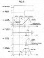
- a mode 1, a mode 2, a mode 3, and a mode 4 in Fig. 4(c) and Fig. 5(c) which will be described below, respectively correspond to the first control mode, the second control mode, the third control mode, and the fourth control mode.
- the first control mode (a low-pressure filling mode) is started at a time point (time t 0 ) at which the INH signal is switched from the N range (the non-travel range) to the D range (the travel range).
- the clutch instruction (command) pressure is first increased in a stepwise manner to pre-charge pressure Ppr and is maintained until a predetermined pre-charge time Tpr elapses. In this way, an invalid stroke of the forward clutch piston is promptly reduced.
- the pre-charge time Tpr is set to a time duration of such a degree that is required for the invalid stroke of the forward clutch piston to become zero and for the forward clutch 32 not to transmit torque in a case where the pre-charge pressure Ppr is supplied to the forward clutch piston chamber 32a, for example.
- the clutch instruction (command) pressure is lowered to a predetermined pressure Pfi that is slightly higher than torque 0 point hydraulic pressure.
- torque 0 point hydraulic pressure is a hydraulic pressure at which the forward clutch 32 can be retained in a contact state of such a degree that the torque is not transmitted.
- the engagement of the forward clutch 32 is gradually started by increasing the clutch instruction (command) pressure. Since the drive wheel 80 is stopped at this time, the turbine rotational speed Nt starts being decreased in conjunction with a degree of progress of the engagement of the forward clutch 32.
- the control mode is switched from the low-pressure filling mode to the capacity control mode at a time point (time t 2 ) at which the turbine rotational speed Nt reaches an engagement start determination threshold N1.
- the engagement start determination threshold N1 is a speed threshold for determining whether the engagement of the forward clutch 32 is started and is preset to a rotational speed that is decreased by a predetermined rotational speed from the turbine rotational speed Nt at a time when the INH signal is switched from the N range to the D range.
- the low-pressure filling mode of the ordinary selection control is a control mode that is executed in a period from a time point that the INH signal is switched from the N range to the D range until the turbine rotational speed Nt reaches the engagement start determination threshold N1.
- the clutch instruction (command) pressure is increased from the predetermined pressure Pfi in a ramp shape with a small inclination and the engagement of the forward clutch 32 is progressed. It should be noted that the forward clutch 32 is rapidly engaged when the forward clutch pressure Pfc is excessively high. Thus, the forward clutch pressure Pfc is controlled here to oil pressure that is slightly higher than the clutch instruction (command) pressure in the first control mode. Then, the control mode is switched from the second control mode to the third control mode at a time point (time t 3 ) at which the turbine rotational speed Nt reaches an engagement completion determination threshold N2.
- the engagement completion determination threshold N2 is a smaller value than the above-described engagement start determination threshold N1 (N1 > N2), is a threshold speed for determining whether the forward clutch 32 is engaged, and is preset to such a rotational speed that a deviation between the turbine rotational speed Nt and an engine speed Ne falls within a predetermined value, for example.
- the capacity control mode of the ordinary selection control is a control mode that is executed in a period from a time point at which the turbine rotational speed Nt reaches the engagement start determination threshold N1 until the turbine rotational speed Nt reaches the engagement completion determination threshold N2.
- the clutch instruction (command) pressure is increased in the ramp shape with a predetermined inclination for a predetermined assurance time Tfa. In this way, the forward clutch 32 is completely engaged (a time t 4 ).
- the third control mode of the ordinary selection control is executed for the assurance time Tfa from a time point at which the turbine rotational speed Nt reaches the engagement completion determination threshold N2, and the control mode is switched from the third control mode to the fourth control mode at a time t 5 .
- the clutch instruction (command) pressure is controlled to be lowered in the ramp shape and become a predetermined hydraulic pressure.
- the first control mode (the low-pressure filling mode) is started from the time point (the time t 0 ) at which the INH signal is switched from the N range to the D range.
- the first control mode is similar to that of the ordinary selection control.
- the manual valve 57 is not completely switched from a state corresponding to the N range to a state corresponding to the D range and, thus, does not completely bring the clutch pressure regulator 14 and the oil passage for achieving the D range into the communication state.
- the oil pressure is hardly supplied to the forward clutch piston chamber 32a. For this reason, the progress of the engagement of the forward clutch 32 is delayed and, thus, the turbine rotational speed Nt hardly changes.
- the control mode is switched from the first control mode to the second control mode at this time point.
- This first predetermined time T1 is set to a longer time than a time that is required for the turbine rotational speed Nt to reach the engagement start determination threshold N1 in a case where the INH signal matches (is coincident with) the communication state of the manual valve 57.
- the control of the clutch instruction (command) pressure in the first control mode is executed from the time point at which the INH signal is switched from the N range to the D range.
- the ordinary selection control is selected in a case where the turbine rotational speed Nt reaches the engagement start determination threshold N1 in a period from the start of the first control mode until the first predetermined time T1 elapses.
- the pseudo D selection control is selected in a case where the turbine rotational speed Nt does not change even after the first predetermined time T1 elapses.
- the clutch instruction (command) pressure Is increased in the ramp shape.
- the clutch instruction (command) pressure is increased in the ramp shape.
- the third control mode is executed from a time point at which the engagement of the forward clutch 32 is completed, that is, a time point (time t 10 ) at which the deviation between the turbine rotational speed Nt and the engine speed Ne becomes equal to or higher than a predetermined rotation speed until a third predetermined time T3 elapses. Thereafter, the control mode is switched to the fourth control mode.
- the third predetermined time T3 is set in an equivalent manner to the assurance time Tfa.
- the second control mode of the pseudo D selection control is shifted to the second control mode of the ordinary selection control. That is, when the turbine rotational speed Nt reaches the engagement completion determination threshold N2, the third control mode of the ordinary selection control is executed from the time point for the assurance time Tfa.
- the clutch pressure is controlled to be lowered in the ramp shape and become the predetermined hydraulic pressure.
- the similar selection control is executed in a case where the selection lever 50 is switched from the P range to the D range.
- the selection control for engaging the reverse brake 33 is executed. In this selection control, the reverse brake instruction (command) pressure is controlled in the similar manner as described above.
- the pulley pressure control is a control related to the primary pressure Ppri and the secondary pressure Psec (hereinafter, these will collectively be referred to as a pulley pressure) and is executed in a case where the selection control is executed.
- the pulley pressure control is executed in accordance with the selected selection control (that is, the ordinary selection control or the pseudo D selection control). Furthermore, in a case where the pseudo D selection control is selected, the pulley pressure is controlled in accordance with the control mode.
- the pulley pressure control in a case where the ordinary selection control is selected will be described.
- the secondary instruction (command) pressure is controlled to a preset ordinary instruction (command) pressure (hereinafter simply referred to as an ordinary secondary pressure Psec_us).
- a magnitude of the ordinary secondary pressure Psec_us is preset to such a degree that the belt slippage does not occur due to the torque that is transmitted to the belt 43 during the engagement of the forward clutch 32 through the ordinary selection control and the ordinary secondary pressure Psec_us has a constant value herein.
- the pulley pressure control in a case where the pseudo D selection control is selected will be described.
- the secondary instruction (command) pressure is controlled to a higher hydraulic pressure of the above-described ordinary secondary pressure Psec_us and a minimum pressure Psec_low.
- This minimum pressure Psec_low is the secondary pressure Psec that is minimally required to suppress the belt slippage during the engagement of the forward clutch 32 through the pseudo D selection control and is set in accordance with the control mode of the pseudo D selection control.
- the INH signal is first switched from the N range to the D range, which is followed by the displacement of the manual valve 57.
- the clutch instruction (command) pressure that is instructed (commanded) to the clutch pressure regulator 14 is gradually increased from time at which the INH signal is switched and the clutch source pressure (the hydraulic pressure that is held in the oil passage on the clutch pressure regulator 14 side than the manual valve 57) is also accordingly increased.
- the manual valve 57 is switched to be in the communication state with the oil passage that leads to the forward clutch piston chamber 32a In this state, the high clutch source pressure is supplied to the forward clutch piston chamber 32a.
- the forward clutch pressure Pfc is, then, rapidly increased, and the forward clutch 32 is rapidly engaged.
- the ordinary secondary pressure Psec_us becomes insufficient for the pulley pressure and there is a possibility that the belt slippage occurs.
- the minimum pressure Psec_low as another control pressure is provided to suppress such a belt slippage and the higher hydraulic pressure of the ordinary secondary pressure Psec_us and the minimum pressure Psec_low is used.
- the minimum pressure Psec_low is controlled to zero in the first control mode and is gradually increased at the same time when the control mode is switched to the second control mode.
- the minimum pressure Psec_low is increased in the ramp shape.
- the first predetermined pressure P1 is maintained until the second control mode is terminated.
- the secondary instruction (command) pressure is controlled to the ordinary secondary pressure Psec_us in the first control mode, and the secondary instruction (command) pressure is switched from the ordinary secondary pressure Psec_us to the minimum pressure Psec_low in a midway of the control mode, in the second control mode.
- the minimum pressure Psec_low is increased again in the ramp shape from a time point at which the control mode is switched to the third control mode and is increased to second predetermined pressure P2 that is higher than the first predetermined pressure P1. Then, after reaching the second predetermined pressure P2, the second predetermined pressure P2 is maintained until the third control mode is terminated.
- the secondary instruction (command) pressure is controlled to the minimum pressure Psec_low in the third control mode.
- the minimum pressure Psec_low is lowered to zero in the ramp shape.
- the secondary instruction (command) pressure is switched from the minimum pressure Psec_low to the ordinary secondary pressure Psec_us at a time point at which the minimum pressure Psec_low falls below the ordinary secondary pressure Psec_us.
- the first predetermined pressure P1 and the second predetermined pressure P2 are each the secondary pressure Psec that is minimally required to suppress the belt slippage during the engagement of the forward clutch 32 in the second control mode and the third control mode and are preset. That is, the secondary instruction (command) pressure is increased by the predetermined quantities P1, P2 to the hydraulic pressure at which the belt slippage does not occur even when the forward clutch 32 is engaged in any of the control modes. Since the clutch Instruction (command) pressure is higher in the third control mode than in the second control mode, the torque input during the engagement of the forward clutch 32 is larger in the third control mode. Thus, the second predetermined pressure P2 is set to be higher than the first predetermined pressure P1.
- the controller 60 is provided with a determination section 60a, a selection control section 60b, and a pulley pressure control section 60c as elements for executing the above-described control.
- a determination section 60a a selection control section 60b
- a pulley pressure control section 60c a pulley pressure control section 60c as elements for executing the above-described control.
- Each of these elements may be realized by an electronic circuit (a hardware) or may be programmed as a software. Alternatively, some of functions of these may be provided as the hardware, and the rest thereof may be provided as the software.
- the determination section (determination means) 60a determines the engagement states of the clutches 32, 33 after the INH signal is switched from the non-travel range to the travel range.
- the engagement states are determined by using the turbine rotational speed Nt that Is detected by the turbine rotational speed sensor 67. Since the drive wheel 80 is stopped at a time point at which the INH signal is switched from the non-travel range to the travel range, the turbine rotational speed Nt is decreased due to a brake action along with progress of the engagement of the clutches 32, 33. Accordingly, the turbine rotational speed Nt is compared with preset predetermined thresholds N1, N2 .
- the determination section 60a determines whether the following (A) is established after the INH signal is switched from the non-travel range to the travel range, and further determines whether the following (B) is established when determining that (A) is established,
- the determination section 60a determines that the engagement of the clutches 32, 33 is started when determining that the above (A) is established and determines that the clutches 32, 33 are disengaged (released) when determining that (A) Is not established. In addition, the determination section 60a determines that the engagement of the clutches 32, 33 is completed when determining that the above (B) is established, and determines that the clutches 32, 33 are currently being engaged when determining that (B) Is not established. A determination result at the determination section 60a is transmitted to the selection control section 60b.
- the selection control section (selection control means) 60b executes the above-described selection control by using the INH signal, the timer, and the determination result that is transmitted from the determination section 60a.
- the selection control section 60b detects that the INH signal is switched from the non-travel range to the travel range, and starts the selection control at this switching time point.
- the control mode at a start of the selection control is the first control mode.
- the selection control section 60b increases the clutch instruction (command) pressure to the pre-charge pressure Ppr from the switching time point of the INH signal, lowers the clutch instruction (command) pressure to the predetermined pressure Pfi at a time point at which the pre-charge time Tpr elapses, and maintains the predetermined pressure Pfi until the control mode is switched to the second control mode.
- the selection control section 60b selects the ordinary selection control in a case where the determination section 60a determines that the engagement of the clutches 32, 33 is started before a time point at which the first predetermined time T1 elapses from a time point at which the first control mode is started.
- the selection control section 60b selects the pseudo D selection control in a case where the determination section 60a determines that the clutches 32, 33 are disengaged at the time point at which the first predetermined time T1 elapses from the time point at which the first control mode is started.
- the selection control section 60b executes the control in the second control mode until the determination section 60a determines that the engagement of the clutches 32, 33 is completed. That is to say, the clutch instruction (command) pressure is increased from the predetermined pressure Pfi in the ramp shape with a predetermined inclination. Then, when the determination section 60a determines that the engagement of the clutches 32, 33 is completed, the control mode is switched to the third control mode, and the clutch instruction (command) pressure is increased in the ramp shape for the predetermined assurance time Tfa. Thereafter, the control mode is switched to the fourth control mode at a time point at which the assurance time Tfa elapses, the clutch instruction (command) pressure is lowered in the ramp shape, and the predetermined hydraulic pressure is maintained.
- the selection control section 60b executes the control in the second control mode at the time point at which the first predetermined time T1 elapses from the start of the first control mode. That is to say, the clutch instruction (command) pressure is increased in the ramp shape with the predetermined inclination from the predetermined pressure Pfi. Then, the control mode is switched to the third control mode at a time point at which the second predetermined time T2 elapses from a start of the second control mode, and the clutch instruction (command) pressure is increased in the ramp shape.
- the selection control section 60b switches the control mode from the third control mode to the fourth control mode at a time point at which the third predetermined time T3 elapses from the time point at which the determination section 60a determines that the engagement of the clutches 32, 33 is completed, lowers the clutch instruction (command) pressure in the ramp shape, and maintains the predetermined hydraulic pressure. It should be noted that, in a case where the determination section 60a determines that the engagement of the clutches 32, 33 is completed during the execution of second control mode, the selection control section 60b switches from the second control mode of the pseudo D selection control to the second control mode of the ordinary selection control.
- Contents of the control in the selection control section 60b are transmitted to the pulley pressure control section 60c. That is to say, that the selection control has been executed, a type of the executed selection control (the ordinary selection control or the pseudo D selection control), and the control mode in a case of the pseudo D selection control are transmitted to the pulley pressure control section 60c.
- the pulley pressure control section (pulley pressure control means) 60c executes the above-described pulley pressure control in accordance with the selection control by the selection control section 60b.
- the pulley pressure control section 60c starts the pulley pressure control when the selection control is started by the selection control section 60b.
- the secondary instruction (command) pressure is controlled to the preset ordinary secondary pressure Psec_us.
- the minimum pressure Psec_low is controlled in accordance with the control mode and the secondary instruction (command) pressure is controlled to the higher hydraulic pressure of the ordinary secondary pressure Psec_us, which is calculated on a basis of the input torque and a pulley ratio, and the minimum pressure Psec_low.
- the pulley pressure control section 60c controls the minimum pressure Psec_low to zero in the first control mode.
- the minimum pressure Psec_low is increased in the ramp shape and is maintained to be constant at the first predetermined pressure P1 after reaching the first predetermined pressure P1.
- the minimum pressure Psec_low Is increased in the ramp shape and is maintained to be constant at the second predetermined pressure P2 after reaching the second predetermined pressure P2.
- the pulley pressure control section 60c increases the minimum pressure Psec_low in accordance with a degree of progress of the pseudo D selection control by the selection control section 60b and thereby increases the secondary instruction (command) pressure.
- the pulley pressure control section 60c lowers the minimum pressure Psec_low in the ramp shape in the fourth control mode and maintains the minimum pressure Psec_low to be constant at zero after reaching zero.
- controller 60 determines in a step S10 whether the pseudo D selection control is being executed in the selection control section 60b. It should be noted that whether the ordinary selection control or the pseudo D selection control is selected is not indicated in this flow; however, if a condition to select the pseudo D selection control is established (a condition for the ordinary selection control is not established) after the first predetermined time T1 elapses from the start of the control, the pseudo D selection control is selected from this time point, and if the condition to select the pseudo D selection control is not established, the ordinary selection control is selected.
- step S150 the secondary instruction (command) pressure is controlled to the ordinary secondary pressure Psec_us, and this calculation interval is returned. That is, at a start of this flow, the process proceeds from step S10 to step S150, and the secondary instruction (command) pressure is controlled to the ordinary secondary pressure Psec_us. Then, if the ordinary selection control is selected in a period from the start of the flow (the start of the selection control) until the first predetermined time T1 elapses, the secondary instruction (command) pressure is constantly controlled to the ordinary secondary pressure Psec_us.
- the pseudo D selection control is selected at the time point at which the first predetermined time T1 elapses, and the process proceeds to a step S20.
- the first control mode of the pseudo D selection control has already been terminated. That is to say, since the minimum pressure Psec_low is set to zero in the first control mode, the secondary instruction (command) pressure is controlled to the ordinary secondary pressure Psec_us at the step S150 without exception.
- the controller 60 determines in the step S10 that the pseudo D selection control is being executed, the control mode is obtained in the step S20.
- the controller 60 determines whether the control mode is the second control mode. In a case of the second control mode, the process proceeds to a step S40. It should be noted that the second control mode is selected at the start of the pseudo D selection control.
- a pressure that is obtained by adding a first ramp pressure Pr 1 to the minimum pressure Psec_low in a previous interval is set as a new minimum pressure Psec_low.
- the controller 60 determines, at the following step S50, whether the minimum pressure Psec_low is equal to or above the first predetermined pressure P1. If the minimum pressure Psec_low is lower than the first predetermined pressure P1, the process proceeds to a step S140. At the step S140, the higher hydraulic pressure of the minimum pressure Psec_low and the ordinary secondary pressure Psec_us is set to the secondary instruction (command) pressure and this calculation interval is returned. As long as the second control mode of the pseudo D selection control is continued, the first ramp pressure Pr 1 is added to the minimum pressure Psec_low at the step S40 and the minimum pressure Psec_low is increased in the ramp shape.
- the process proceeds from the step S50 to a step S60.
- the minimum pressure Psec_low is set to the first predetermined pressure P1 and the process proceeds to the step S140.
- the process proceeds from the step S30 to a step S70 and the controller 60 determines whether the control mode of the pseudo D selection control is in the third control mode. Since It is in the third control mode, in this case, the process proceeds from the step S70 to a step S80 and, at the step S80, the pressure that is obtained by adding a second ramp pressure Pr 2 to the minimum pressure Psec_low in the previous interval is set to the new minimum pressure Psec_low. At the following step S90, it is determined whether the minimum pressure Psec_low is equal to or above the second predetermined pressure P2. If the minimum pressure Psec_low is lower than the second predetermined pressure P2, the process proceeds to the step S140.
- the second ramp pressure Pr 2 is added to the minimum pressure Psec_low at the step S80 and the minimum pressure Psec_low is increased in the ramp shape. Then, when the minimum pressure Psec_low becomes equal to or above the second predetermined pressure P2, the process proceeds from the step S90 to a step S100, at the step S100, the minimum pressure Psec_low is set to the second predetermined pressure P2, and the process proceeds to the step S140. It should be noted that, in a case of this third control mode, the minimum pressure Psec_low is set to the secondary instruction (command) pressure at the step S140.
- the process proceeds from the step S70 to a step S110. Then, the pressure that is obtained by subtracting third ramp pressure Pr 3 from the minimum pressure Psec_low at the previous interval is set as the new minimum pressure Psec_low.
- the controller 60 determines whether the minimum pressure Psec_low is equal to or below zero, and, if Psec_low is higher than zero, the process proceeds from the step S120 to the step S140.
- the minimum pressure Psec_low becomes equal to or below zero, the minimum pressure Psec_low is set to zero at a step S130, and the process proceeds to the step S140. Then, when the fourth control mode is terminated, this flow Is terminated.
- Fig. 4 is the timing chart in a case where the INH signal matches (is coincident with) the communication state of the manual valve 57 (the ordinary selection control)
- Fig. 5 is the timing chart in a case where the INH signal does not match (coincident with) the communication state of the manual valve 57 (the pseudo D selection control).
- the actual pressure of the clutch pressure (a broken line) is promptly increased due to the pre-charge and is controlled to the hydraulic pressure that is substantially the same as the clutch instruction (command) pressure.
- the transmission torque of the clutches 32, 33 (a solid line) is increased along the actual clutch pressure (a torque capacity) until the time t 4 at which the clutches 32, 33 are completely engaged, is lowered to a predetermined torque at the time t 4 , and, thereafter, gives a constant value.
- the secondary instruction (command) pressure (the pulley pressure) becomes constant at the ordinary secondary pressure Psec_us, in the ordinary selection control.
- the minimum pressure Psec_low is increased in the ramp shape to the first predetermined pressure P1 and becomes constant at the first predetermined pressure P1. In this way, the slippage of the belt 43 is prevented even when the clutches 32, 33 are engaged during the second control mode.
- the clutch instruction (command) pressure Is is further increased.
- the manual valve 57 is displaced at a time t 8 during the third control mode and matches (coincident with) the INH signal. Accordingly, the actual clutch pressure starts being increased, and is rapidly increased to the clutch instruction (command) pressure at once from a time t 9 at which the actual clutch pressure reaches the torque 0 point hydraulic pressure.
- the turbine rotational speed Nt is lowered at once from the time t 9 , and the deviation between the turbine rotational speed Nt and the engine speed Ne becomes equal to or above the predetermined rotation speed at the time t 10 . That is to say, the clutches 32, 33 are completely engaged at the time t 10 .
- the secondary instruction (command) pressure (the pulley pressure) is increased in a case where the clutches 32, 33 are disengaged (released) even after the first predetermined time T1 elapses from the start of the selection control.
- the belt slippage that is caused by the rapid engagement of the clutches 32, 33 can be suppressed.
- the secondary instruction (command) pressure Is lowered when the clutches 32, 33 are engaged.
- the load on the oil pump 10 can be reduced. Accordingly, in a case where the oil pump 10 uses the engine 70 as the drive source, the fuel economy (consumption) performance can be enhanced by reducing the load on the oil pump 10.
- the pulley pressure control section 60c increases the secondary instruction (command) pressure In accordance with the degree of the progress of the selection control of the selection control section 60b. That is to say, the secondary instruction (command) pressure is increased to the first predetermined pressure P1 in the second control mode, in accordance with the control mode of the pseudo D selection control, and the secondary instruction (command) pressure is increased to the second predetermined pressure P2 in the third control mode.
- the clutch instruction (command) pressure is gradually increased from the time point at which the first predetermined time T1 elapses from the start of the selection control (that is, the time point at which the control mode is switched to the second control mode).
- the pulley pressure control section 60c increases the secondary instruction (command) pressure to the hydraulic pressure at which the belt slippage does not occur during the engagement of the clutches.
- the load on the oil pump 10 can be suppressed to a minimally required load while the belt slippage is suppressed.
- the determination section 60a determines the engagement states of the clutches 32, 33 by using the turbine rotational speed Nt, the engagement states of the clutches 32, 33 can accurately and easily be determined.
- control mode is switched by using the timer, in the pseudo D selection control.
- the pulley pressure control section 60c increases the secondary instruction (command) pressure to the second predetermined pressure P2 in a case where the clutches 32, 33 are engaged in either mode of the second control mode and the third control mode. That is to say, since the similar control logic is used, the control configuration can be simplified.
- this control apparatus even in a case where the selection lever 50 is slowly operated and the accelerator pedal is depressed after the pseudo D state, the belt slippage can be suppressed since the pulley pressure is controlled and a startability can also be secured.
- the secondary pressure Psec is controlled, as the pulley pressure
- the primary pressure Ppri may be controlled.
- the pulley pressure may be increased not in the ramp shape but in a stepwise manner, or in place of the increase in two stages of the first predetermined pressure P1 and the second predetermined pressure P2, the pulley pressure may be increased in the ramp shape to the second predetermined pressure P2 with a predetermined inclination from the time t 6 in Fig. 5(f) , for example.
- the timing at which the pulley pressure is lowered is not limited to the timing that has been described above. That is to say, the pulley pressure may be lowered at the timing immediately after the engagement of the clutches 32, 33.
- the minimum pressure Psec_low is controlled in accordance with the control mode of the selection control and the higher oil pressure of the ordinary secondary pressure Psec_us and the minimum pressure Psec_low is set to the secondary instruction (command) pressure.
- a control method for the secondary instruction (command) pressure is not limited to this.
- only the minimum pressure Psec_low is provided without providing the control pressure called the ordinary secondary pressure Psec_us, and this minimum pressure Psec_low is set as the secondary instruction (command) pressure.
- the contents of the selection control by the selection control section 60b are not limited to those that have been described above and contents of the control of the clutch pressure in each of the control modes may be other than those that have been described above.
- another control mode may be provided.
- a component that detects the operation position of the selection lever 50 is not limited to the Inhibitor switch 65 but may be a detector, such as an AT shift position sensor, that can detect the operation position of the selection lever 50 and can output an electrical signal.
- the oil pump is not limited to the oil pump that uses the engine 70 as the drive source.
Landscapes
- Engineering & Computer Science (AREA)
- General Engineering & Computer Science (AREA)
- Mechanical Engineering (AREA)
- Control Of Transmission Device (AREA)
Applications Claiming Priority (2)
| Application Number | Priority Date | Filing Date | Title |
|---|---|---|---|
| JP2013220422 | 2013-10-23 | ||
| PCT/JP2014/077628 WO2015060204A1 (ja) | 2013-10-23 | 2014-10-17 | 無段変速機の制御装置 |
Publications (3)
| Publication Number | Publication Date |
|---|---|
| EP3061994A1 EP3061994A1 (en) | 2016-08-31 |
| EP3061994A4 EP3061994A4 (en) | 2017-01-04 |
| EP3061994B1 true EP3061994B1 (en) | 2018-03-21 |
Family
ID=52992801
Family Applications (1)
| Application Number | Title | Priority Date | Filing Date |
|---|---|---|---|
| EP14855144.3A Not-in-force EP3061994B1 (en) | 2013-10-23 | 2014-10-17 | Control device for continuously variable transmission |
Country Status (6)
| Country | Link |
|---|---|
| US (1) | US9863533B2 (ja) |
| EP (1) | EP3061994B1 (ja) |
| JP (1) | JP6063580B2 (ja) |
| KR (1) | KR101828190B1 (ja) |
| CN (1) | CN105518351B (ja) |
| WO (1) | WO2015060204A1 (ja) |
Families Citing this family (3)
| Publication number | Priority date | Publication date | Assignee | Title |
|---|---|---|---|---|
| DE102017114430A1 (de) * | 2017-06-29 | 2019-01-03 | Schaeffler Technologies AG & Co. KG | Hydrauliksystem |
| DE102019127419A1 (de) * | 2019-10-11 | 2021-04-15 | Schaeffler Technologies AG & Co. KG | Notbetriebsverfahren für ein Umschlingungsgetriebe bei Anpressdruckabfall, sowie Antriebsstrang |
| JPWO2022162809A1 (ja) * | 2021-01-28 | 2022-08-04 |
Family Cites Families (13)
| Publication number | Priority date | Publication date | Assignee | Title |
|---|---|---|---|---|
| GB2076483B (en) * | 1980-03-24 | 1984-02-01 | Aisin Warner | R vehicles control system for a continuously variable transmission fo |
| US6146308A (en) * | 1996-10-03 | 2000-11-14 | Aisin Aw Co., Ltd. | Creep torque control of infinitely variable transmission |
| JP2001304388A (ja) * | 2000-04-25 | 2001-10-31 | Mitsubishi Motors Corp | ベルト式無段変速機の切換制御装置 |
| JP2004263741A (ja) * | 2003-02-28 | 2004-09-24 | Jatco Ltd | 自動変速機のクラッチ締結制御装置 |
| JP4145856B2 (ja) * | 2004-10-05 | 2008-09-03 | ジヤトコ株式会社 | ベルト式無段変速機のライン圧制御装置 |
| JP4358130B2 (ja) * | 2005-02-22 | 2009-11-04 | ジヤトコ株式会社 | 自動変速機の油圧制御装置 |
| JP4323461B2 (ja) * | 2005-05-25 | 2009-09-02 | ジヤトコ株式会社 | 自動変速装置 |
| JP4532384B2 (ja) * | 2005-10-06 | 2010-08-25 | ジヤトコ株式会社 | ベルト式無段変速機の変速比制御装置 |
| JP2007263130A (ja) | 2006-03-27 | 2007-10-11 | Jatco Ltd | 変速機の制御装置 |
| JP4344379B2 (ja) * | 2006-12-06 | 2009-10-14 | ジヤトコ株式会社 | 無段変速機の制御装置 |
| JP4787855B2 (ja) * | 2008-03-17 | 2011-10-05 | ジヤトコ株式会社 | 無段変速機の制御装置 |
| JP2009222155A (ja) * | 2008-03-17 | 2009-10-01 | Jatco Ltd | 無段変速機の制御装置 |
| JP4965612B2 (ja) * | 2009-08-25 | 2012-07-04 | ジヤトコ株式会社 | 自動変速機の制御装置 |
-
2014
- 2014-10-17 US US15/021,501 patent/US9863533B2/en active Active
- 2014-10-17 EP EP14855144.3A patent/EP3061994B1/en not_active Not-in-force
- 2014-10-17 WO PCT/JP2014/077628 patent/WO2015060204A1/ja active Application Filing
- 2014-10-17 JP JP2015543823A patent/JP6063580B2/ja active Active
- 2014-10-17 KR KR1020167005730A patent/KR101828190B1/ko active IP Right Grant
- 2014-10-17 CN CN201480049604.3A patent/CN105518351B/zh active Active
Non-Patent Citations (1)
| Title |
|---|
| None * |
Also Published As
| Publication number | Publication date |
|---|---|
| EP3061994A1 (en) | 2016-08-31 |
| EP3061994A4 (en) | 2017-01-04 |
| KR20160041963A (ko) | 2016-04-18 |
| US20160223077A1 (en) | 2016-08-04 |
| WO2015060204A1 (ja) | 2015-04-30 |
| KR101828190B1 (ko) | 2018-02-09 |
| US9863533B2 (en) | 2018-01-09 |
| JPWO2015060204A1 (ja) | 2017-03-09 |
| CN105518351B (zh) | 2017-06-16 |
| JP6063580B2 (ja) | 2017-01-18 |
| CN105518351A (zh) | 2016-04-20 |
Similar Documents
| Publication | Publication Date | Title |
|---|---|---|
| US7815545B2 (en) | Hydraulic control system for automatic transmission | |
| JP5435137B2 (ja) | 車両用無段変速機の制御装置 | |
| US8690733B2 (en) | Vehicle control system and control method thereof | |
| US10001179B2 (en) | Control apparatus for power transmission system | |
| JP2008133881A (ja) | ベルト式無段変速機の油圧制御装置 | |
| US7524264B2 (en) | Vehicle controller of a vehicle power transmission device | |
| US9026328B2 (en) | Automatic transmission and starting time control method | |
| EP3061994B1 (en) | Control device for continuously variable transmission | |
| US6960153B2 (en) | Clutch engagement control of automatic transmission | |
| JP5811016B2 (ja) | 無段変速機の制御装置 | |
| US10683928B2 (en) | Transmission control device and transmission control method | |
| US9194487B2 (en) | System and method for automatically downshifting an automatic transmission with alternate forward launch gear | |
| JP5692030B2 (ja) | 車両用油圧制御装置 | |
| CN114096746B (zh) | 车辆的控制装置及车辆的控制方法 | |
| US10005445B2 (en) | Hydraulic control device for automatic transmission and control method therefor | |
| CN114126937B (zh) | 车辆的控制装置及车辆的控制方法 | |
| JP6984575B2 (ja) | 動力伝達機構の制御装置 | |
| JP5533556B2 (ja) | 車両の制御装置 | |
| US8977451B2 (en) | Vehicle, control apparatus and control method for equipment | |
| US11524670B2 (en) | Control device for vehicle and control method for vehicle | |
| JP2011106505A (ja) | 車両用無段変速機の制御装置 | |
| JP2010025246A (ja) | 車両の変速制御装置 | |
| US20200347933A1 (en) | Control method for power transmission device, and control device for power transmission device |
Legal Events
| Date | Code | Title | Description |
|---|---|---|---|
| PUAI | Public reference made under article 153(3) epc to a published international application that has entered the european phase |
Free format text: ORIGINAL CODE: 0009012 |
|
| 17P | Request for examination filed |
Effective date: 20160307 |
|
| AK | Designated contracting states |
Kind code of ref document: A1 Designated state(s): AL AT BE BG CH CY CZ DE DK EE ES FI FR GB GR HR HU IE IS IT LI LT LU LV MC MK MT NL NO PL PT RO RS SE SI SK SM TR |
|
| AX | Request for extension of the european patent |
Extension state: BA ME |
|
| A4 | Supplementary search report drawn up and despatched |
Effective date: 20161202 |
|
| RIC1 | Information provided on ipc code assigned before grant |
Ipc: F16H 61/662 20060101ALI20161128BHEP Ipc: F16H 61/02 20060101AFI20161128BHEP |
|
| DAX | Request for extension of the european patent (deleted) | ||
| GRAP | Despatch of communication of intention to grant a patent |
Free format text: ORIGINAL CODE: EPIDOSNIGR1 |
|
| INTG | Intention to grant announced |
Effective date: 20170928 |
|
| GRAS | Grant fee paid |
Free format text: ORIGINAL CODE: EPIDOSNIGR3 |
|
| GRAA | (expected) grant |
Free format text: ORIGINAL CODE: 0009210 |
|
| AK | Designated contracting states |
Kind code of ref document: B1 Designated state(s): AL AT BE BG CH CY CZ DE DK EE ES FI FR GB GR HR HU IE IS IT LI LT LU LV MC MK MT NL NO PL PT RO RS SE SI SK SM TR |
|
| REG | Reference to a national code |
Ref country code: GB Ref legal event code: FG4D |
|
| REG | Reference to a national code |
Ref country code: CH Ref legal event code: EP |
|
| RAP2 | Party data changed (patent owner data changed or rights of a patent transferred) |
Owner name: JATCO LTD Owner name: NISSAN MOTOR CO., LTD. |
|
| REG | Reference to a national code |
Ref country code: AT Ref legal event code: REF Ref document number: 981457 Country of ref document: AT Kind code of ref document: T Effective date: 20180415 |
|
| REG | Reference to a national code |
Ref country code: IE Ref legal event code: FG4D |
|
| REG | Reference to a national code |
Ref country code: DE Ref legal event code: R096 Ref document number: 602014022805 Country of ref document: DE |
|
| REG | Reference to a national code |
Ref country code: NL Ref legal event code: MP Effective date: 20180321 |
|
| PG25 | Lapsed in a contracting state [announced via postgrant information from national office to epo] |
Ref country code: CY Free format text: LAPSE BECAUSE OF FAILURE TO SUBMIT A TRANSLATION OF THE DESCRIPTION OR TO PAY THE FEE WITHIN THE PRESCRIBED TIME-LIMIT Effective date: 20180321 Ref country code: FI Free format text: LAPSE BECAUSE OF FAILURE TO SUBMIT A TRANSLATION OF THE DESCRIPTION OR TO PAY THE FEE WITHIN THE PRESCRIBED TIME-LIMIT Effective date: 20180321 Ref country code: LT Free format text: LAPSE BECAUSE OF FAILURE TO SUBMIT A TRANSLATION OF THE DESCRIPTION OR TO PAY THE FEE WITHIN THE PRESCRIBED TIME-LIMIT Effective date: 20180321 Ref country code: HR Free format text: LAPSE BECAUSE OF FAILURE TO SUBMIT A TRANSLATION OF THE DESCRIPTION OR TO PAY THE FEE WITHIN THE PRESCRIBED TIME-LIMIT Effective date: 20180321 Ref country code: NO Free format text: LAPSE BECAUSE OF FAILURE TO SUBMIT A TRANSLATION OF THE DESCRIPTION OR TO PAY THE FEE WITHIN THE PRESCRIBED TIME-LIMIT Effective date: 20180621 |
|
| REG | Reference to a national code |
Ref country code: LT Ref legal event code: MG4D |
|
| REG | Reference to a national code |
Ref country code: AT Ref legal event code: MK05 Ref document number: 981457 Country of ref document: AT Kind code of ref document: T Effective date: 20180321 |
|
| PG25 | Lapsed in a contracting state [announced via postgrant information from national office to epo] |
Ref country code: BG Free format text: LAPSE BECAUSE OF FAILURE TO SUBMIT A TRANSLATION OF THE DESCRIPTION OR TO PAY THE FEE WITHIN THE PRESCRIBED TIME-LIMIT Effective date: 20180621 Ref country code: RS Free format text: LAPSE BECAUSE OF FAILURE TO SUBMIT A TRANSLATION OF THE DESCRIPTION OR TO PAY THE FEE WITHIN THE PRESCRIBED TIME-LIMIT Effective date: 20180321 Ref country code: GR Free format text: LAPSE BECAUSE OF FAILURE TO SUBMIT A TRANSLATION OF THE DESCRIPTION OR TO PAY THE FEE WITHIN THE PRESCRIBED TIME-LIMIT Effective date: 20180622 Ref country code: SE Free format text: LAPSE BECAUSE OF FAILURE TO SUBMIT A TRANSLATION OF THE DESCRIPTION OR TO PAY THE FEE WITHIN THE PRESCRIBED TIME-LIMIT Effective date: 20180321 Ref country code: LV Free format text: LAPSE BECAUSE OF FAILURE TO SUBMIT A TRANSLATION OF THE DESCRIPTION OR TO PAY THE FEE WITHIN THE PRESCRIBED TIME-LIMIT Effective date: 20180321 |
|
| REG | Reference to a national code |
Ref country code: FR Ref legal event code: PLFP Year of fee payment: 5 |
|
| PG25 | Lapsed in a contracting state [announced via postgrant information from national office to epo] |
Ref country code: RO Free format text: LAPSE BECAUSE OF FAILURE TO SUBMIT A TRANSLATION OF THE DESCRIPTION OR TO PAY THE FEE WITHIN THE PRESCRIBED TIME-LIMIT Effective date: 20180321 Ref country code: PL Free format text: LAPSE BECAUSE OF FAILURE TO SUBMIT A TRANSLATION OF THE DESCRIPTION OR TO PAY THE FEE WITHIN THE PRESCRIBED TIME-LIMIT Effective date: 20180321 Ref country code: ES Free format text: LAPSE BECAUSE OF FAILURE TO SUBMIT A TRANSLATION OF THE DESCRIPTION OR TO PAY THE FEE WITHIN THE PRESCRIBED TIME-LIMIT Effective date: 20180321 Ref country code: NL Free format text: LAPSE BECAUSE OF FAILURE TO SUBMIT A TRANSLATION OF THE DESCRIPTION OR TO PAY THE FEE WITHIN THE PRESCRIBED TIME-LIMIT Effective date: 20180321 Ref country code: AL Free format text: LAPSE BECAUSE OF FAILURE TO SUBMIT A TRANSLATION OF THE DESCRIPTION OR TO PAY THE FEE WITHIN THE PRESCRIBED TIME-LIMIT Effective date: 20180321 Ref country code: EE Free format text: LAPSE BECAUSE OF FAILURE TO SUBMIT A TRANSLATION OF THE DESCRIPTION OR TO PAY THE FEE WITHIN THE PRESCRIBED TIME-LIMIT Effective date: 20180321 Ref country code: IT Free format text: LAPSE BECAUSE OF FAILURE TO SUBMIT A TRANSLATION OF THE DESCRIPTION OR TO PAY THE FEE WITHIN THE PRESCRIBED TIME-LIMIT Effective date: 20180321 |
|
| PG25 | Lapsed in a contracting state [announced via postgrant information from national office to epo] |
Ref country code: AT Free format text: LAPSE BECAUSE OF FAILURE TO SUBMIT A TRANSLATION OF THE DESCRIPTION OR TO PAY THE FEE WITHIN THE PRESCRIBED TIME-LIMIT Effective date: 20180321 Ref country code: SM Free format text: LAPSE BECAUSE OF FAILURE TO SUBMIT A TRANSLATION OF THE DESCRIPTION OR TO PAY THE FEE WITHIN THE PRESCRIBED TIME-LIMIT Effective date: 20180321 Ref country code: CZ Free format text: LAPSE BECAUSE OF FAILURE TO SUBMIT A TRANSLATION OF THE DESCRIPTION OR TO PAY THE FEE WITHIN THE PRESCRIBED TIME-LIMIT Effective date: 20180321 Ref country code: SK Free format text: LAPSE BECAUSE OF FAILURE TO SUBMIT A TRANSLATION OF THE DESCRIPTION OR TO PAY THE FEE WITHIN THE PRESCRIBED TIME-LIMIT Effective date: 20180321 |
|
| PG25 | Lapsed in a contracting state [announced via postgrant information from national office to epo] |
Ref country code: PT Free format text: LAPSE BECAUSE OF FAILURE TO SUBMIT A TRANSLATION OF THE DESCRIPTION OR TO PAY THE FEE WITHIN THE PRESCRIBED TIME-LIMIT Effective date: 20180723 |
|
| REG | Reference to a national code |
Ref country code: DE Ref legal event code: R097 Ref document number: 602014022805 Country of ref document: DE |
|
| PLBE | No opposition filed within time limit |
Free format text: ORIGINAL CODE: 0009261 |
|
| STAA | Information on the status of an ep patent application or granted ep patent |
Free format text: STATUS: NO OPPOSITION FILED WITHIN TIME LIMIT |
|
| PG25 | Lapsed in a contracting state [announced via postgrant information from national office to epo] |
Ref country code: DK Free format text: LAPSE BECAUSE OF FAILURE TO SUBMIT A TRANSLATION OF THE DESCRIPTION OR TO PAY THE FEE WITHIN THE PRESCRIBED TIME-LIMIT Effective date: 20180321 |
|
| PGFP | Annual fee paid to national office [announced via postgrant information from national office to epo] |
Ref country code: DE Payment date: 20181026 Year of fee payment: 5 |
|
| 26N | No opposition filed |
Effective date: 20190102 |
|
| PGFP | Annual fee paid to national office [announced via postgrant information from national office to epo] |
Ref country code: FR Payment date: 20181119 Year of fee payment: 10 |
|
| PG25 | Lapsed in a contracting state [announced via postgrant information from national office to epo] |
Ref country code: SI Free format text: LAPSE BECAUSE OF FAILURE TO SUBMIT A TRANSLATION OF THE DESCRIPTION OR TO PAY THE FEE WITHIN THE PRESCRIBED TIME-LIMIT Effective date: 20180321 |
|
| REG | Reference to a national code |
Ref country code: CH Ref legal event code: PL |
|
| REG | Reference to a national code |
Ref country code: BE Ref legal event code: MM Effective date: 20181031 |
|
| PG25 | Lapsed in a contracting state [announced via postgrant information from national office to epo] |
Ref country code: MC Free format text: LAPSE BECAUSE OF FAILURE TO SUBMIT A TRANSLATION OF THE DESCRIPTION OR TO PAY THE FEE WITHIN THE PRESCRIBED TIME-LIMIT Effective date: 20180321 Ref country code: LU Free format text: LAPSE BECAUSE OF NON-PAYMENT OF DUE FEES Effective date: 20181017 |
|
| REG | Reference to a national code |
Ref country code: IE Ref legal event code: MM4A |
|
| PG25 | Lapsed in a contracting state [announced via postgrant information from national office to epo] |
Ref country code: BE Free format text: LAPSE BECAUSE OF NON-PAYMENT OF DUE FEES Effective date: 20181031 Ref country code: CH Free format text: LAPSE BECAUSE OF NON-PAYMENT OF DUE FEES Effective date: 20181031 Ref country code: LI Free format text: LAPSE BECAUSE OF NON-PAYMENT OF DUE FEES Effective date: 20181031 |
|
| PG25 | Lapsed in a contracting state [announced via postgrant information from national office to epo] |
Ref country code: IE Free format text: LAPSE BECAUSE OF NON-PAYMENT OF DUE FEES Effective date: 20181017 |
|
| PG25 | Lapsed in a contracting state [announced via postgrant information from national office to epo] |
Ref country code: MT Free format text: LAPSE BECAUSE OF NON-PAYMENT OF DUE FEES Effective date: 20181017 |
|
| PG25 | Lapsed in a contracting state [announced via postgrant information from national office to epo] |
Ref country code: TR Free format text: LAPSE BECAUSE OF FAILURE TO SUBMIT A TRANSLATION OF THE DESCRIPTION OR TO PAY THE FEE WITHIN THE PRESCRIBED TIME-LIMIT Effective date: 20180321 |
|
| REG | Reference to a national code |
Ref country code: DE Ref legal event code: R119 Ref document number: 602014022805 Country of ref document: DE |
|
| PG25 | Lapsed in a contracting state [announced via postgrant information from national office to epo] |
Ref country code: MK Free format text: LAPSE BECAUSE OF NON-PAYMENT OF DUE FEES Effective date: 20180321 Ref country code: HU Free format text: LAPSE BECAUSE OF FAILURE TO SUBMIT A TRANSLATION OF THE DESCRIPTION OR TO PAY THE FEE WITHIN THE PRESCRIBED TIME-LIMIT; INVALID AB INITIO Effective date: 20141017 |
|
| PG25 | Lapsed in a contracting state [announced via postgrant information from national office to epo] |
Ref country code: DE Free format text: LAPSE BECAUSE OF NON-PAYMENT OF DUE FEES Effective date: 20200501 Ref country code: IS Free format text: LAPSE BECAUSE OF FAILURE TO SUBMIT A TRANSLATION OF THE DESCRIPTION OR TO PAY THE FEE WITHIN THE PRESCRIBED TIME-LIMIT Effective date: 20180721 |
|
| PG25 | Lapsed in a contracting state [announced via postgrant information from national office to epo] |
Ref country code: FR Free format text: LAPSE BECAUSE OF NON-PAYMENT OF DUE FEES Effective date: 20191031 |
|
| PGFP | Annual fee paid to national office [announced via postgrant information from national office to epo] |
Ref country code: GB Payment date: 20201007 Year of fee payment: 7 |
|
| GBPC | Gb: european patent ceased through non-payment of renewal fee |
Effective date: 20211017 |
|
| PG25 | Lapsed in a contracting state [announced via postgrant information from national office to epo] |
Ref country code: GB Free format text: LAPSE BECAUSE OF NON-PAYMENT OF DUE FEES Effective date: 20211017 |