EP3059191B1 - Machine et procédé de convoyage d'articles - Google Patents
Machine et procédé de convoyage d'articles Download PDFInfo
- Publication number
- EP3059191B1 EP3059191B1 EP16156571.8A EP16156571A EP3059191B1 EP 3059191 B1 EP3059191 B1 EP 3059191B1 EP 16156571 A EP16156571 A EP 16156571A EP 3059191 B1 EP3059191 B1 EP 3059191B1
- Authority
- EP
- European Patent Office
- Prior art keywords
- items
- conveyor belt
- comb
- articles
- robotic
- Prior art date
- Legal status (The legal status is an assumption and is not a legal conclusion. Google has not performed a legal analysis and makes no representation as to the accuracy of the status listed.)
- Active
Links
- 238000000034 method Methods 0.000 title claims description 28
- 238000004519 manufacturing process Methods 0.000 claims description 33
- 230000002950 deficient Effects 0.000 claims description 24
- 230000001360 synchronised effect Effects 0.000 claims description 18
- 238000011144 upstream manufacturing Methods 0.000 claims description 14
- 239000002699 waste material Substances 0.000 claims description 11
- 238000007599 discharging Methods 0.000 claims 5
- 235000014676 Phragmites communis Nutrition 0.000 description 35
- 238000006073 displacement reaction Methods 0.000 description 15
- 230000001105 regulatory effect Effects 0.000 description 3
- 235000012431 wafers Nutrition 0.000 description 3
- 230000001276 controlling effect Effects 0.000 description 2
- 238000005034 decoration Methods 0.000 description 2
- 235000021185 dessert Nutrition 0.000 description 2
- 238000011143 downstream manufacturing Methods 0.000 description 2
- 239000000463 material Substances 0.000 description 2
- 238000005259 measurement Methods 0.000 description 2
- 230000003287 optical effect Effects 0.000 description 2
- 238000009516 primary packaging Methods 0.000 description 2
- 238000012545 processing Methods 0.000 description 2
- 208000031968 Cadaver Diseases 0.000 description 1
- 230000004323 axial length Effects 0.000 description 1
- 235000013351 cheese Nutrition 0.000 description 1
- 239000006071 cream Substances 0.000 description 1
- 235000013365 dairy product Nutrition 0.000 description 1
- 238000000605 extraction Methods 0.000 description 1
- 239000012530 fluid Substances 0.000 description 1
- 235000015243 ice cream Nutrition 0.000 description 1
- 239000008267 milk Substances 0.000 description 1
- 235000013336 milk Nutrition 0.000 description 1
- 210000004080 milk Anatomy 0.000 description 1
- 238000004806 packaging method and process Methods 0.000 description 1
- 238000012856 packing Methods 0.000 description 1
- 238000011084 recovery Methods 0.000 description 1
- 238000000926 separation method Methods 0.000 description 1
- 230000035939 shock Effects 0.000 description 1
- 239000007787 solid Substances 0.000 description 1
- 238000003856 thermoforming Methods 0.000 description 1
- 238000013519 translation Methods 0.000 description 1
- 235000013618 yogurt Nutrition 0.000 description 1
- 229910000859 α-Fe Inorganic materials 0.000 description 1
Images


Classifications
-
- B—PERFORMING OPERATIONS; TRANSPORTING
- B65—CONVEYING; PACKING; STORING; HANDLING THIN OR FILAMENTARY MATERIAL
- B65G—TRANSPORT OR STORAGE DEVICES, e.g. CONVEYORS FOR LOADING OR TIPPING, SHOP CONVEYOR SYSTEMS OR PNEUMATIC TUBE CONVEYORS
- B65G47/00—Article or material-handling devices associated with conveyors; Methods employing such devices
- B65G47/74—Feeding, transfer, or discharging devices of particular kinds or types
- B65G47/90—Devices for picking-up and depositing articles or materials
-
- B—PERFORMING OPERATIONS; TRANSPORTING
- B65—CONVEYING; PACKING; STORING; HANDLING THIN OR FILAMENTARY MATERIAL
- B65G—TRANSPORT OR STORAGE DEVICES, e.g. CONVEYORS FOR LOADING OR TIPPING, SHOP CONVEYOR SYSTEMS OR PNEUMATIC TUBE CONVEYORS
- B65G15/00—Conveyors having endless load-conveying surfaces, i.e. belts and like continuous members, to which tractive effort is transmitted by means other than endless driving elements of similar configuration
-
- B—PERFORMING OPERATIONS; TRANSPORTING
- B65—CONVEYING; PACKING; STORING; HANDLING THIN OR FILAMENTARY MATERIAL
- B65G—TRANSPORT OR STORAGE DEVICES, e.g. CONVEYORS FOR LOADING OR TIPPING, SHOP CONVEYOR SYSTEMS OR PNEUMATIC TUBE CONVEYORS
- B65G47/00—Article or material-handling devices associated with conveyors; Methods employing such devices
- B65G47/74—Feeding, transfer, or discharging devices of particular kinds or types
- B65G47/90—Devices for picking-up and depositing articles or materials
- B65G47/901—Devices for picking-up and depositing articles or materials provided with drive systems with rectilinear movements only
-
- B—PERFORMING OPERATIONS; TRANSPORTING
- B65—CONVEYING; PACKING; STORING; HANDLING THIN OR FILAMENTARY MATERIAL
- B65G—TRANSPORT OR STORAGE DEVICES, e.g. CONVEYORS FOR LOADING OR TIPPING, SHOP CONVEYOR SYSTEMS OR PNEUMATIC TUBE CONVEYORS
- B65G47/00—Article or material-handling devices associated with conveyors; Methods employing such devices
- B65G47/02—Devices for feeding articles or materials to conveyors
- B65G47/04—Devices for feeding articles or materials to conveyors for feeding articles
- B65G47/06—Devices for feeding articles or materials to conveyors for feeding articles from a single group of articles arranged in orderly pattern, e.g. workpieces in magazines
- B65G47/08—Devices for feeding articles or materials to conveyors for feeding articles from a single group of articles arranged in orderly pattern, e.g. workpieces in magazines spacing or grouping the articles during feeding
- B65G47/084—Devices for feeding articles or materials to conveyors for feeding articles from a single group of articles arranged in orderly pattern, e.g. workpieces in magazines spacing or grouping the articles during feeding grouping articles in a predetermined 2-dimensional pattern
- B65G47/088—Devices for feeding articles or materials to conveyors for feeding articles from a single group of articles arranged in orderly pattern, e.g. workpieces in magazines spacing or grouping the articles during feeding grouping articles in a predetermined 2-dimensional pattern cylindrical articles
Definitions
- the invention relates to the conveying of articles, in particular in a production line.
- Such an article typically contains, or is typically intended to contain, a content that is homogeneous or not, presenting a more or less fluid overall state, possibly including more or less solid pieces.
- a content is for example a milk product or a dessert, this list not being exhaustive.
- the problem underlying the invention is therefore to propose a method and a conveying machine which make it possible to keep information on the relative position and the relative orientation of the articles during the conveying so as to allow downstream processing of the articles without preliminary repositioning.
- the invention also aims to provide such a method and such a conveying machine which are inexpensive and easily adaptable.
- the articles are contacted only from below, in a vertical direction.
- a robotic comb is lowered vertically, relative to the fixed conveyor belt, so as to bring the articles to rest on the belt conveying.
- the robotic comb is lowered vertically relative to the conveyor belt over a vertical travel greater than the predefined vertical spacing, so that the articles lose contact with the robotic comb at the end of said vertical stroke.
- a robotic comb is moved only in the vertical direction and in a horizontal direction, the horizontal direction being in particular the direction of movement of the conveyor belt.
- the presence or absence of defective articles among the seized articles is determined from the measured physical characteristic, and if the presence of defective articles among the seized articles is determined, the seized articles are evacuated.
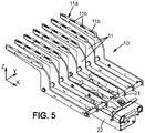
- the conveyor belt comprises a plurality of conveyor belts, synchronized, aligned with a predefined transverse pitch in the transverse direction perpendicular to the direction of movement of the conveyor belt, and spaced from each other in the transverse direction by transverse spacings of bands able to accommodate the longitudinal fingers of the robotic comb.
- the robotic reed comprises a frame on which the longitudinal fingers are mounted and a reed body integral with the displacement means, the frame and the reed body being fixed together by removable assembly means.
- the incoming batch support comprises a plurality of support pots of a cutting tool of a production line.
- the articles A can comprise at least a lower extension portion A1 and an upper portion A2 as is visible on the figure 8 , the upper portion A2 being arranged above the lower extension portion A1 in the vertical direction Z.
- the upper portion A2 has a greater transverse size than a transverse size of the lower extension portion A1.
- the lower die 27 comprises for example a plurality of openings distributed in the horizontal plane and forming cavities capable of receiving the pot supports 3 when the lower die 27 rises relative to the pot supports 3.
- the upper part 28 of the cutting tool 4 carries knives 28a which are arranged to come opposite grooves 27a made in the lower die at the desired cutting locations, so that the material of the articles A is sandwiched between the knives and grooves to be cut out.
- the upper part 28 may also include strippers 28b to facilitate the extraction of the articles A after cutting.
- one of the lower die 27, the upper part 28 and the pot supports 3 can for example be fixed, in particular the pot supports 3, while the others, in particular the lower die 27 and the upper part 28, can move along the vertical axis.
- the displacement of the conveyor belt 6 is carried out with a displacement speed V in the longitudinal direction X.
- displacement is meant that said at least one conveying belt 7 is driven in motion with a non-zero displacement speed V at least over part of an operating period of the conveying machine.
- speed of movement is thus meant a linear speed of said at least one conveyor belt 7 of the conveyor belt, for example in the frame of reference of the fixed frame 8 of the conveyor belt 6.
- the magnetic assembly means comprises a first element 24 mounted on the reed body 22 and a second element 25 mounted on the frame 21.
- the first element 24 and the second element 25 are such that a magnetic attraction force can exist between them when these elements are in proximity.
- the first element 24 can comprise a magnet while the second element 25 comprises a ferrite or vice versa.
- Said magnetic attraction force may in particular be sufficiently intense to secure the frame 21 to the reed body 22 in normal operation, that is to say when the forces exerted on the frame 21 and the reed body 22 are not top intense.
- the predefined magnetic attraction force can thus be calibrated by the choice of a permanent magnet for the first element 24 and/or the second element 25, and an adjustment of an air gap between the first element 24 and the second element 25, for example by means of peelable wedges.
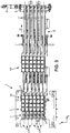
- the longitudinal fingers 11 are regularly aligned so as to present a predefined transverse pitch Py identical to the transverse pitch of the articles A arranged on, or in, the incoming batch support 2.
- the longitudinal fingers 11 advantageously present, on at least one active portion of said longitudinal fingers 11, a transverse finger size Ed less than the transverse gripping spacings Ey separating the longitudinal columns C so as to be able to be introduced between the longitudinal columns C without touching the articles A of the said longitudinal columns C.
- the robotic comb 10 is moreover arranged in such a way that two neighboring longitudinal fingers 11 are able to transversely surround the articles A of a longitudinal column C and to support the articles A of the said longitudinal column in order to grasp them and bring them vertically. conveyor belt 6.
- the longitudinal grooves 12 are deep enough to accommodate the longitudinal fingers 11 of the robotic comb 10, when the articles A of the incoming batch L are placed on, or in, the incoming batch support 2, without said longitudinal fingers 11 entering in contact with the articles A of the incoming batch L.
- the incoming batch support 2 comprises a plurality of pot supports 3
- the grooves are formed in particular by the spaces separating the pot supports.
- Such a first routing section P1-P2 of the robotic comb 10 thus belongs to an inactive routing section of the robotic comb 10, illustrated in dotted lines on the figures 12 to 14 , that is to say a section of path on which the robotic comb does not perform any function of carrying the articles A.
- the moving means 13 raise the robotic reed 10 vertically, relative to the incoming batch support 2 horizontal, keeping the robotic reed 10 horizontal, so as to come contact, and lift from incoming lot 2 rack, items A of incoming lot L.
- moving the articles in the vertical direction simultaneously it is meant that all the articles A of the incoming batch are moved simultaneously, that is to say with a relative speed of the articles with respect to each other zero.
- the means of movement 13 may comprise means 14 capable of moving the robotic reed 10 in the vertical direction Z with the fingers 11 of the horizontal comb.
- These means 14 comprise for example an eccentric assembly controlled by a motor.
- the incoming batch support 2 is lowered vertically, relative to the horizontal robotic comb 10, on or in which the articles A are arranged, while maintaining said incoming batch support 2 horizontal, so as to come rest the articles A of the incoming batch L on the robotic comb 10 and in particular on the longitudinal fingers 11 of the robotic comb 10.
- the articles A are contacted only from below, in the vertical direction Z. More precisely, it is possible in particular to come and contact by below the upper portion A2 of the articles A by transversely surrounding the lower portion A1.
- the moving means 13 of the robotic reed 10 move the robotic reed 10 on a third path section P3-P4, to bring the articles A vertically to the conveyor belt 6 as illustrated in the figure 9 .
- the longitudinal fingers 11 of the robotic comb 10 each have an upper face 11a provided with a plurality of structures 11b, for example notches or extra thickness structures.
- the structures 11b are for example distributed along the longitudinal direction X of the longitudinal fingers 11 and able to wedge in the horizontal plane H the articles A seized during the movement of the robotic comb 10 in the horizontal plane H.
- the means of movement 13 of the robotic comb 10 can for example position the robotic comb 10 so that the upstream end of the robotic comb 10 is placed above the evacuation hole 17, if necessary close from the downstream end of the evacuation hole 17. Then, the means for evacuating defective articles detected 19 can sweep the articles A placed on the robotic comb 10 to cause them to fall into the evacuation hole 17.
- the adjustment and synchronization means 20 can also be connected to the drive motor 9 of the conveyor belt 6, or to a displacement speed sensor of the conveyor belt 6, so as to allow fine adjustment of the speed of movement of the articles A seized, that is to say the speed of movement of the robotic comb 10, with the speed of movement of the conveyor belt 6.
- the means of movement 13 of the robotic comb 10 are then implemented to move the articles A in the vertical direction Z , simultaneously, to bring the articles A to rest on the conveyor belt 6.
- the robotic comb 10 is moved over a fifth path section P5-P6 belonging to an active path section.
- the robotic comb 10 is lowered vertically in the vertical direction Z, relative to the fixed conveyor belt 6, by the means 14 capable of moving the robotic comb 10 in the vertical direction Z, while maintaining the horizontal movement of the articles A synchronized with the speed of movement V of the conveyor belt 6 thanks to the means 15 controlling the robotic comb 10 in the longitudinal direction X.
- the sixth path section thus belongs to an inactive path section of the robotic comb 10, illustrated in dotted lines on the figures 12 to 14 , that is to say a section of path on which the robotic comb does not perform any function of carrying the articles A.
Priority Applications (1)
| Application Number | Priority Date | Filing Date | Title |
|---|---|---|---|
| PL16156571T PL3059191T4 (pl) | 2015-02-20 | 2016-02-19 | Maszyna i sposób przenoszenia artykułów |
Applications Claiming Priority (1)
| Application Number | Priority Date | Filing Date | Title |
|---|---|---|---|
| FR1551481A FR3032950B1 (fr) | 2015-02-20 | 2015-02-20 | Machine et procede de convoyage d'articles |
Publications (2)
| Publication Number | Publication Date |
|---|---|
| EP3059191A1 EP3059191A1 (fr) | 2016-08-24 |
| EP3059191B1 true EP3059191B1 (fr) | 2022-01-12 |
Family
ID=53059277
Family Applications (1)
| Application Number | Title | Priority Date | Filing Date |
|---|---|---|---|
| EP16156571.8A Active EP3059191B1 (fr) | 2015-02-20 | 2016-02-19 | Machine et procédé de convoyage d'articles |
Country Status (7)
| Country | Link |
|---|---|
| US (1) | US9764907B2 (pl) |
| EP (1) | EP3059191B1 (pl) |
| JP (1) | JP6715615B2 (pl) |
| CN (1) | CN105905520B (pl) |
| ES (1) | ES2911237T3 (pl) |
| FR (1) | FR3032950B1 (pl) |
| PL (1) | PL3059191T4 (pl) |
Families Citing this family (4)
| Publication number | Priority date | Publication date | Assignee | Title |
|---|---|---|---|---|
| CN107176448A (zh) * | 2017-07-10 | 2017-09-19 | 中国大冢制药有限公司 | 安瓿制品自动分离系统 |
| FR3075769B1 (fr) * | 2017-12-27 | 2021-12-17 | Gebo Packaging Solutions France | Transfert de produits entre une zone de transit et une surface d'accumulation |
| CN109231123A (zh) * | 2018-10-30 | 2019-01-18 | 四川击瓦云智能科技有限公司 | 一种多通道瓶体输送装置 |
| WO2023137524A1 (en) * | 2022-01-20 | 2023-07-27 | Matthew Ian Angilley | Automated punnets handling assembly |
Citations (1)
| Publication number | Priority date | Publication date | Assignee | Title |
|---|---|---|---|---|
| EP2668124A1 (en) * | 2011-01-25 | 2013-12-04 | CARLE & MONTANARI - OPM S.p.A. | Annular conveyor |
Family Cites Families (10)
| Publication number | Priority date | Publication date | Assignee | Title |
|---|---|---|---|---|
| US4191003A (en) * | 1978-04-19 | 1980-03-04 | Talarico Lawrence J | Tray loader |
| US4457121A (en) * | 1982-09-27 | 1984-07-03 | Standard-Knapp, Inc. | Continuous motion bottle packer |
| CA1267716A (en) | 1984-02-23 | 1990-04-10 | Frederick W. Scholl | Edge-emitting light emitting diode |
| IT1219312B (it) * | 1988-05-18 | 1990-05-03 | Cavanna Spa | Procedimento e relativo impianto per il trattamento di articoli particolarmente per linee di confezionamento automatico |
| FR2673611B1 (fr) | 1991-03-05 | 1995-09-01 | Merlin Gerin | Dispositif rapide d'amenage et de positionnement a cinematique rectangulaire allongee. |
| IT1304279B1 (it) * | 1998-04-21 | 2001-03-13 | Zecchetti Srl | Dispositivo per alimentare strati di oggetti ad un impianto dipalettizzazione. |
| FR2792920B1 (fr) * | 1999-04-27 | 2001-06-15 | Loire Etudes Realisations Meca | Installation et procede de convoyage de produits selon deux directions |
| IT1318125B1 (it) * | 2000-07-05 | 2003-07-23 | Vortex Systems Srl | Apparecchiatura di alimentazione di gruppi di prodotti ad untrasportatore per il loro imballaggio. |
| DE10127896B4 (de) * | 2001-06-08 | 2005-02-24 | Indag Gesellschaft für Industriebedarf mbH & Co. Betriebs KG | Übergabevorrichtung und -verfahren für Folienbeutel |
| US7467504B2 (en) * | 2005-09-23 | 2008-12-23 | Delkor Systems, Inc. | Packaging system for split package assembly |
-
2015
- 2015-02-20 FR FR1551481A patent/FR3032950B1/fr active Active
-
2016
- 2016-02-12 US US15/042,337 patent/US9764907B2/en active Active
- 2016-02-19 CN CN201610092760.9A patent/CN105905520B/zh active Active
- 2016-02-19 ES ES16156571T patent/ES2911237T3/es active Active
- 2016-02-19 EP EP16156571.8A patent/EP3059191B1/fr active Active
- 2016-02-19 PL PL16156571T patent/PL3059191T4/pl unknown
- 2016-02-19 JP JP2016029705A patent/JP6715615B2/ja active Active
Patent Citations (1)
| Publication number | Priority date | Publication date | Assignee | Title |
|---|---|---|---|---|
| EP2668124A1 (en) * | 2011-01-25 | 2013-12-04 | CARLE & MONTANARI - OPM S.p.A. | Annular conveyor |
Also Published As
| Publication number | Publication date |
|---|---|
| US20160244272A1 (en) | 2016-08-25 |
| FR3032950A1 (fr) | 2016-08-26 |
| US9764907B2 (en) | 2017-09-19 |
| CN105905520A (zh) | 2016-08-31 |
| PL3059191T3 (pl) | 2022-07-11 |
| JP2016179858A (ja) | 2016-10-13 |
| ES2911237T3 (es) | 2022-05-18 |
| CN105905520B (zh) | 2020-08-04 |
| FR3032950B1 (fr) | 2017-03-17 |
| PL3059191T4 (pl) | 2022-07-11 |
| EP3059191A1 (fr) | 2016-08-24 |
| JP6715615B2 (ja) | 2020-07-01 |
Similar Documents
| Publication | Publication Date | Title |
|---|---|---|
| EP2341001B1 (fr) | Procédé et machine de suremballage d'articles pour former des lots d'articles, du type comprenant une certaine pluralité d'articles et un suremballage en carton | |
| EP3059191B1 (fr) | Machine et procédé de convoyage d'articles | |
| EP2648978B1 (fr) | Procede et dispositif d'encaissage destines a realiser un encaissage sequentiel de lots de produits a l'interieur de receptacles de conditionnement | |
| WO2019129968A1 (fr) | Déplacement de produits sur une zone de transit | |
| EP3317186B1 (fr) | Dispositif et méthode de constitution de lots | |
| EP3802377A1 (fr) | Transfert de produits en enserrement vers ou depuis une surface d'accumulation | |
| FR3063984A1 (fr) | Realisation de lots de produits en vue d'une palettisation par couches | |
| EP2978697B1 (fr) | Procede et systeme de transfert d'objets | |
| FR2978436A1 (fr) | Installation pour la manutention de produits, en particulier de tranches de denrees alimentaires | |
| WO2013001203A1 (fr) | Procede et machine d'encaissage de produits, avec intercalaire(s) | |
| EP3256409A1 (fr) | Procede et systeme de dechargement de colis | |
| FR3049933A1 (fr) | Systeme et procede de manipulation d'articles tels que recipients a boisson ou similaire | |
| FR2998284A1 (fr) | Dispositif et procede de placement d'une decoupe pour boites d'emballages avec depilage vertical et tapis de transfert. | |
| WO2019243674A1 (fr) | Appareil et procédé de transfert, vers une ligne de traitement, d'imprimés initialement conditionnés en liasse | |
| FR3018793A1 (fr) | Procede de collecte d'au moins un produit et installation assurant la mise en oeuvre du procede | |
| EP3511135B1 (fr) | Installation de decoupe de produits alimentaires equipee de moyens de remplissage de goulotte | |
| FR3060547A1 (fr) | Appareil et procede de transfert, vers une ligne de traitement, d'imprimes initialement conditionnes en liasse | |
| CA3047899C (fr) | Palettisation robotisee | |
| FR3060538A1 (fr) | Procede et appareil pour sectionner un lien entourant une liasse d'imprimes provenant d'une palette | |
| WO2012110723A1 (fr) | Outil de manipulation de produits | |
| EP3075686B1 (fr) | Dispositif et méthode de rotation de produit | |
| FR3088315A1 (fr) | Dispositif de convoyage de produits et procede de gestion du transfert desdits produits | |
| WO2020064860A1 (fr) | Dispositif et procede de transfert de produits | |
| FR2998272A1 (fr) | Installation et procede d'emballage de fruits ou legumes | |
| EP1792857A1 (fr) | Procédé de transfert et de stockage, dans une installation pour l'accumulation et la restitution de produits, et dispositif accumulateur conçu pour la mise en oeuvre du procédé |
Legal Events
| Date | Code | Title | Description |
|---|---|---|---|
| PUAI | Public reference made under article 153(3) epc to a published international application that has entered the european phase |
Free format text: ORIGINAL CODE: 0009012 |
|
| AK | Designated contracting states |
Kind code of ref document: A1 Designated state(s): AL AT BE BG CH CY CZ DE DK EE ES FI FR GB GR HR HU IE IS IT LI LT LU LV MC MK MT NL NO PL PT RO RS SE SI SK SM TR |
|
| AX | Request for extension of the european patent |
Extension state: BA ME |
|
| STAA | Information on the status of an ep patent application or granted ep patent |
Free format text: STATUS: REQUEST FOR EXAMINATION WAS MADE |
|
| 17P | Request for examination filed |
Effective date: 20170221 |
|
| RBV | Designated contracting states (corrected) |
Designated state(s): AL AT BE BG CH CY CZ DE DK EE ES FI FR GB GR HR HU IE IS IT LI LT LU LV MC MK MT NL NO PL PT RO RS SE SI SK SM TR |
|
| RAP1 | Party data changed (applicant data changed or rights of an application transferred) |
Owner name: SYNERLINK |
|
| GRAP | Despatch of communication of intention to grant a patent |
Free format text: ORIGINAL CODE: EPIDOSNIGR1 |
|
| STAA | Information on the status of an ep patent application or granted ep patent |
Free format text: STATUS: GRANT OF PATENT IS INTENDED |
|
| INTG | Intention to grant announced |
Effective date: 20210805 |
|
| GRAS | Grant fee paid |
Free format text: ORIGINAL CODE: EPIDOSNIGR3 |
|
| GRAA | (expected) grant |
Free format text: ORIGINAL CODE: 0009210 |
|
| STAA | Information on the status of an ep patent application or granted ep patent |
Free format text: STATUS: THE PATENT HAS BEEN GRANTED |
|
| AK | Designated contracting states |
Kind code of ref document: B1 Designated state(s): AL AT BE BG CH CY CZ DE DK EE ES FI FR GB GR HR HU IE IS IT LI LT LU LV MC MK MT NL NO PL PT RO RS SE SI SK SM TR |
|
| REG | Reference to a national code |
Ref country code: GB Ref legal event code: FG4D Free format text: NOT ENGLISH |
|
| REG | Reference to a national code |
Ref country code: CH Ref legal event code: EP |
|
| REG | Reference to a national code |
Ref country code: IE Ref legal event code: FG4D Free format text: LANGUAGE OF EP DOCUMENT: FRENCH |
|
| REG | Reference to a national code |
Ref country code: DE Ref legal event code: R096 Ref document number: 602016068253 Country of ref document: DE |
|
| REG | Reference to a national code |
Ref country code: AT Ref legal event code: REF Ref document number: 1462246 Country of ref document: AT Kind code of ref document: T Effective date: 20220215 |
|
| REG | Reference to a national code |
Ref country code: LT Ref legal event code: MG9D |
|
| REG | Reference to a national code |
Ref country code: NL Ref legal event code: MP Effective date: 20220112 Ref country code: ES Ref legal event code: FG2A Ref document number: 2911237 Country of ref document: ES Kind code of ref document: T3 Effective date: 20220518 |
|
| REG | Reference to a national code |
Ref country code: AT Ref legal event code: MK05 Ref document number: 1462246 Country of ref document: AT Kind code of ref document: T Effective date: 20220112 |
|
| PG25 | Lapsed in a contracting state [announced via postgrant information from national office to epo] |
Ref country code: NL Free format text: LAPSE BECAUSE OF FAILURE TO SUBMIT A TRANSLATION OF THE DESCRIPTION OR TO PAY THE FEE WITHIN THE PRESCRIBED TIME-LIMIT Effective date: 20220112 |
|
| PG25 | Lapsed in a contracting state [announced via postgrant information from national office to epo] |
Ref country code: SE Free format text: LAPSE BECAUSE OF FAILURE TO SUBMIT A TRANSLATION OF THE DESCRIPTION OR TO PAY THE FEE WITHIN THE PRESCRIBED TIME-LIMIT Effective date: 20220112 Ref country code: RS Free format text: LAPSE BECAUSE OF FAILURE TO SUBMIT A TRANSLATION OF THE DESCRIPTION OR TO PAY THE FEE WITHIN THE PRESCRIBED TIME-LIMIT Effective date: 20220112 Ref country code: PT Free format text: LAPSE BECAUSE OF FAILURE TO SUBMIT A TRANSLATION OF THE DESCRIPTION OR TO PAY THE FEE WITHIN THE PRESCRIBED TIME-LIMIT Effective date: 20220512 Ref country code: NO Free format text: LAPSE BECAUSE OF FAILURE TO SUBMIT A TRANSLATION OF THE DESCRIPTION OR TO PAY THE FEE WITHIN THE PRESCRIBED TIME-LIMIT Effective date: 20220412 Ref country code: LT Free format text: LAPSE BECAUSE OF FAILURE TO SUBMIT A TRANSLATION OF THE DESCRIPTION OR TO PAY THE FEE WITHIN THE PRESCRIBED TIME-LIMIT Effective date: 20220112 Ref country code: HR Free format text: LAPSE BECAUSE OF FAILURE TO SUBMIT A TRANSLATION OF THE DESCRIPTION OR TO PAY THE FEE WITHIN THE PRESCRIBED TIME-LIMIT Effective date: 20220112 Ref country code: BG Free format text: LAPSE BECAUSE OF FAILURE TO SUBMIT A TRANSLATION OF THE DESCRIPTION OR TO PAY THE FEE WITHIN THE PRESCRIBED TIME-LIMIT Effective date: 20220412 |
|
| PG25 | Lapsed in a contracting state [announced via postgrant information from national office to epo] |
Ref country code: LV Free format text: LAPSE BECAUSE OF FAILURE TO SUBMIT A TRANSLATION OF THE DESCRIPTION OR TO PAY THE FEE WITHIN THE PRESCRIBED TIME-LIMIT Effective date: 20220112 Ref country code: GR Free format text: LAPSE BECAUSE OF FAILURE TO SUBMIT A TRANSLATION OF THE DESCRIPTION OR TO PAY THE FEE WITHIN THE PRESCRIBED TIME-LIMIT Effective date: 20220413 Ref country code: FI Free format text: LAPSE BECAUSE OF FAILURE TO SUBMIT A TRANSLATION OF THE DESCRIPTION OR TO PAY THE FEE WITHIN THE PRESCRIBED TIME-LIMIT Effective date: 20220112 Ref country code: AT Free format text: LAPSE BECAUSE OF FAILURE TO SUBMIT A TRANSLATION OF THE DESCRIPTION OR TO PAY THE FEE WITHIN THE PRESCRIBED TIME-LIMIT Effective date: 20220112 |
|
| PG25 | Lapsed in a contracting state [announced via postgrant information from national office to epo] |
Ref country code: IS Free format text: LAPSE BECAUSE OF FAILURE TO SUBMIT A TRANSLATION OF THE DESCRIPTION OR TO PAY THE FEE WITHIN THE PRESCRIBED TIME-LIMIT Effective date: 20220512 |
|
| REG | Reference to a national code |
Ref country code: DE Ref legal event code: R097 Ref document number: 602016068253 Country of ref document: DE |
|
| REG | Reference to a national code |
Ref country code: CH Ref legal event code: PL |
|
| PG25 | Lapsed in a contracting state [announced via postgrant information from national office to epo] |
Ref country code: SM Free format text: LAPSE BECAUSE OF FAILURE TO SUBMIT A TRANSLATION OF THE DESCRIPTION OR TO PAY THE FEE WITHIN THE PRESCRIBED TIME-LIMIT Effective date: 20220112 Ref country code: SK Free format text: LAPSE BECAUSE OF FAILURE TO SUBMIT A TRANSLATION OF THE DESCRIPTION OR TO PAY THE FEE WITHIN THE PRESCRIBED TIME-LIMIT Effective date: 20220112 Ref country code: RO Free format text: LAPSE BECAUSE OF FAILURE TO SUBMIT A TRANSLATION OF THE DESCRIPTION OR TO PAY THE FEE WITHIN THE PRESCRIBED TIME-LIMIT Effective date: 20220112 Ref country code: MC Free format text: LAPSE BECAUSE OF FAILURE TO SUBMIT A TRANSLATION OF THE DESCRIPTION OR TO PAY THE FEE WITHIN THE PRESCRIBED TIME-LIMIT Effective date: 20220112 Ref country code: LU Free format text: LAPSE BECAUSE OF NON-PAYMENT OF DUE FEES Effective date: 20220219 Ref country code: EE Free format text: LAPSE BECAUSE OF FAILURE TO SUBMIT A TRANSLATION OF THE DESCRIPTION OR TO PAY THE FEE WITHIN THE PRESCRIBED TIME-LIMIT Effective date: 20220112 Ref country code: DK Free format text: LAPSE BECAUSE OF FAILURE TO SUBMIT A TRANSLATION OF THE DESCRIPTION OR TO PAY THE FEE WITHIN THE PRESCRIBED TIME-LIMIT Effective date: 20220112 Ref country code: CZ Free format text: LAPSE BECAUSE OF FAILURE TO SUBMIT A TRANSLATION OF THE DESCRIPTION OR TO PAY THE FEE WITHIN THE PRESCRIBED TIME-LIMIT Effective date: 20220112 |
|
| PLBE | No opposition filed within time limit |
Free format text: ORIGINAL CODE: 0009261 |
|
| STAA | Information on the status of an ep patent application or granted ep patent |
Free format text: STATUS: NO OPPOSITION FILED WITHIN TIME LIMIT |
|
| PG25 | Lapsed in a contracting state [announced via postgrant information from national office to epo] |
Ref country code: AL Free format text: LAPSE BECAUSE OF FAILURE TO SUBMIT A TRANSLATION OF THE DESCRIPTION OR TO PAY THE FEE WITHIN THE PRESCRIBED TIME-LIMIT Effective date: 20220112 |
|
| PGFP | Annual fee paid to national office [announced via postgrant information from national office to epo] |
Ref country code: FR Payment date: 20220719 Year of fee payment: 8 |
|
| 26N | No opposition filed |
Effective date: 20221013 |
|
| PG25 | Lapsed in a contracting state [announced via postgrant information from national office to epo] |
Ref country code: LI Free format text: LAPSE BECAUSE OF NON-PAYMENT OF DUE FEES Effective date: 20220228 Ref country code: IE Free format text: LAPSE BECAUSE OF NON-PAYMENT OF DUE FEES Effective date: 20220219 Ref country code: CH Free format text: LAPSE BECAUSE OF NON-PAYMENT OF DUE FEES Effective date: 20220228 |
|
| PG25 | Lapsed in a contracting state [announced via postgrant information from national office to epo] |
Ref country code: SI Free format text: LAPSE BECAUSE OF FAILURE TO SUBMIT A TRANSLATION OF THE DESCRIPTION OR TO PAY THE FEE WITHIN THE PRESCRIBED TIME-LIMIT Effective date: 20220112 |
|
| PGFP | Annual fee paid to national office [announced via postgrant information from national office to epo] |
Ref country code: ES Payment date: 20230309 Year of fee payment: 8 |
|
| PGFP | Annual fee paid to national office [announced via postgrant information from national office to epo] |
Ref country code: PL Payment date: 20230220 Year of fee payment: 8 Ref country code: GB Payment date: 20230324 Year of fee payment: 8 Ref country code: BE Payment date: 20230227 Year of fee payment: 8 |
|
| PG25 | Lapsed in a contracting state [announced via postgrant information from national office to epo] |
Ref country code: IT Free format text: LAPSE BECAUSE OF FAILURE TO SUBMIT A TRANSLATION OF THE DESCRIPTION OR TO PAY THE FEE WITHIN THE PRESCRIBED TIME-LIMIT Effective date: 20220112 |
|
| PG25 | Lapsed in a contracting state [announced via postgrant information from national office to epo] |
Ref country code: HU Free format text: LAPSE BECAUSE OF FAILURE TO SUBMIT A TRANSLATION OF THE DESCRIPTION OR TO PAY THE FEE WITHIN THE PRESCRIBED TIME-LIMIT; INVALID AB INITIO Effective date: 20160219 |
|
| PGFP | Annual fee paid to national office [announced via postgrant information from national office to epo] |
Ref country code: ES Payment date: 20240306 Year of fee payment: 9 |
|
| PG25 | Lapsed in a contracting state [announced via postgrant information from national office to epo] |
Ref country code: MK Free format text: LAPSE BECAUSE OF FAILURE TO SUBMIT A TRANSLATION OF THE DESCRIPTION OR TO PAY THE FEE WITHIN THE PRESCRIBED TIME-LIMIT Effective date: 20220112 Ref country code: CY Free format text: LAPSE BECAUSE OF FAILURE TO SUBMIT A TRANSLATION OF THE DESCRIPTION OR TO PAY THE FEE WITHIN THE PRESCRIBED TIME-LIMIT Effective date: 20220112 |
|
| PGFP | Annual fee paid to national office [announced via postgrant information from national office to epo] |
Ref country code: DE Payment date: 20240213 Year of fee payment: 9 |