EP3059191B1 - Machine and method for conveying items - Google Patents
Machine and method for conveying items Download PDFInfo
- Publication number
- EP3059191B1 EP3059191B1 EP16156571.8A EP16156571A EP3059191B1 EP 3059191 B1 EP3059191 B1 EP 3059191B1 EP 16156571 A EP16156571 A EP 16156571A EP 3059191 B1 EP3059191 B1 EP 3059191B1
- Authority
- EP
- European Patent Office
- Prior art keywords
- items
- conveyor belt
- comb
- articles
- robotic
- Prior art date
- Legal status (The legal status is an assumption and is not a legal conclusion. Google has not performed a legal analysis and makes no representation as to the accuracy of the status listed.)
- Active
Links
- 238000000034 method Methods 0.000 title claims description 28
- 238000004519 manufacturing process Methods 0.000 claims description 33
- 230000002950 deficient Effects 0.000 claims description 24
- 230000001360 synchronised effect Effects 0.000 claims description 18
- 238000011144 upstream manufacturing Methods 0.000 claims description 14
- 239000002699 waste material Substances 0.000 claims description 11
- 238000007599 discharging Methods 0.000 claims 5
- 235000014676 Phragmites communis Nutrition 0.000 description 35
- 238000006073 displacement reaction Methods 0.000 description 15
- 230000001105 regulatory effect Effects 0.000 description 3
- 235000012431 wafers Nutrition 0.000 description 3
- 230000001276 controlling effect Effects 0.000 description 2
- 238000005034 decoration Methods 0.000 description 2
- 235000021185 dessert Nutrition 0.000 description 2
- 238000011143 downstream manufacturing Methods 0.000 description 2
- 239000000463 material Substances 0.000 description 2
- 238000005259 measurement Methods 0.000 description 2
- 230000003287 optical effect Effects 0.000 description 2
- 238000009516 primary packaging Methods 0.000 description 2
- 238000012545 processing Methods 0.000 description 2
- 208000031968 Cadaver Diseases 0.000 description 1
- 230000004323 axial length Effects 0.000 description 1
- 235000013351 cheese Nutrition 0.000 description 1
- 239000006071 cream Substances 0.000 description 1
- 235000013365 dairy product Nutrition 0.000 description 1
- 238000000605 extraction Methods 0.000 description 1
- 239000012530 fluid Substances 0.000 description 1
- 235000015243 ice cream Nutrition 0.000 description 1
- 239000008267 milk Substances 0.000 description 1
- 235000013336 milk Nutrition 0.000 description 1
- 210000004080 milk Anatomy 0.000 description 1
- 238000004806 packaging method and process Methods 0.000 description 1
- 238000012856 packing Methods 0.000 description 1
- 238000011084 recovery Methods 0.000 description 1
- 238000000926 separation method Methods 0.000 description 1
- 230000035939 shock Effects 0.000 description 1
- 239000007787 solid Substances 0.000 description 1
- 238000003856 thermoforming Methods 0.000 description 1
- 238000013519 translation Methods 0.000 description 1
- 235000013618 yogurt Nutrition 0.000 description 1
- 229910000859 α-Fe Inorganic materials 0.000 description 1
Images


Classifications
-
- B—PERFORMING OPERATIONS; TRANSPORTING
- B65—CONVEYING; PACKING; STORING; HANDLING THIN OR FILAMENTARY MATERIAL
- B65G—TRANSPORT OR STORAGE DEVICES, e.g. CONVEYORS FOR LOADING OR TIPPING, SHOP CONVEYOR SYSTEMS OR PNEUMATIC TUBE CONVEYORS
- B65G47/00—Article or material-handling devices associated with conveyors; Methods employing such devices
- B65G47/74—Feeding, transfer, or discharging devices of particular kinds or types
- B65G47/90—Devices for picking-up and depositing articles or materials
-
- B—PERFORMING OPERATIONS; TRANSPORTING
- B65—CONVEYING; PACKING; STORING; HANDLING THIN OR FILAMENTARY MATERIAL
- B65G—TRANSPORT OR STORAGE DEVICES, e.g. CONVEYORS FOR LOADING OR TIPPING, SHOP CONVEYOR SYSTEMS OR PNEUMATIC TUBE CONVEYORS
- B65G15/00—Conveyors having endless load-conveying surfaces, i.e. belts and like continuous members, to which tractive effort is transmitted by means other than endless driving elements of similar configuration
-
- B—PERFORMING OPERATIONS; TRANSPORTING
- B65—CONVEYING; PACKING; STORING; HANDLING THIN OR FILAMENTARY MATERIAL
- B65G—TRANSPORT OR STORAGE DEVICES, e.g. CONVEYORS FOR LOADING OR TIPPING, SHOP CONVEYOR SYSTEMS OR PNEUMATIC TUBE CONVEYORS
- B65G47/00—Article or material-handling devices associated with conveyors; Methods employing such devices
- B65G47/74—Feeding, transfer, or discharging devices of particular kinds or types
- B65G47/90—Devices for picking-up and depositing articles or materials
- B65G47/901—Devices for picking-up and depositing articles or materials provided with drive systems with rectilinear movements only
-
- B—PERFORMING OPERATIONS; TRANSPORTING
- B65—CONVEYING; PACKING; STORING; HANDLING THIN OR FILAMENTARY MATERIAL
- B65G—TRANSPORT OR STORAGE DEVICES, e.g. CONVEYORS FOR LOADING OR TIPPING, SHOP CONVEYOR SYSTEMS OR PNEUMATIC TUBE CONVEYORS
- B65G47/00—Article or material-handling devices associated with conveyors; Methods employing such devices
- B65G47/02—Devices for feeding articles or materials to conveyors
- B65G47/04—Devices for feeding articles or materials to conveyors for feeding articles
- B65G47/06—Devices for feeding articles or materials to conveyors for feeding articles from a single group of articles arranged in orderly pattern, e.g. workpieces in magazines
- B65G47/08—Devices for feeding articles or materials to conveyors for feeding articles from a single group of articles arranged in orderly pattern, e.g. workpieces in magazines spacing or grouping the articles during feeding
- B65G47/084—Devices for feeding articles or materials to conveyors for feeding articles from a single group of articles arranged in orderly pattern, e.g. workpieces in magazines spacing or grouping the articles during feeding grouping articles in a predetermined 2-dimensional pattern
- B65G47/088—Devices for feeding articles or materials to conveyors for feeding articles from a single group of articles arranged in orderly pattern, e.g. workpieces in magazines spacing or grouping the articles during feeding grouping articles in a predetermined 2-dimensional pattern cylindrical articles
Definitions
- the invention relates to the conveying of articles, in particular in a production line.
- Such an article typically contains, or is typically intended to contain, a content that is homogeneous or not, presenting a more or less fluid overall state, possibly including more or less solid pieces.
- a content is for example a milk product or a dessert, this list not being exhaustive.
- the problem underlying the invention is therefore to propose a method and a conveying machine which make it possible to keep information on the relative position and the relative orientation of the articles during the conveying so as to allow downstream processing of the articles without preliminary repositioning.
- the invention also aims to provide such a method and such a conveying machine which are inexpensive and easily adaptable.
- the articles are contacted only from below, in a vertical direction.
- a robotic comb is lowered vertically, relative to the fixed conveyor belt, so as to bring the articles to rest on the belt conveying.
- the robotic comb is lowered vertically relative to the conveyor belt over a vertical travel greater than the predefined vertical spacing, so that the articles lose contact with the robotic comb at the end of said vertical stroke.
- a robotic comb is moved only in the vertical direction and in a horizontal direction, the horizontal direction being in particular the direction of movement of the conveyor belt.
- the presence or absence of defective articles among the seized articles is determined from the measured physical characteristic, and if the presence of defective articles among the seized articles is determined, the seized articles are evacuated.
- the conveyor belt comprises a plurality of conveyor belts, synchronized, aligned with a predefined transverse pitch in the transverse direction perpendicular to the direction of movement of the conveyor belt, and spaced from each other in the transverse direction by transverse spacings of bands able to accommodate the longitudinal fingers of the robotic comb.
- the robotic reed comprises a frame on which the longitudinal fingers are mounted and a reed body integral with the displacement means, the frame and the reed body being fixed together by removable assembly means.
- the incoming batch support comprises a plurality of support pots of a cutting tool of a production line.
- the articles A can comprise at least a lower extension portion A1 and an upper portion A2 as is visible on the figure 8 , the upper portion A2 being arranged above the lower extension portion A1 in the vertical direction Z.
- the upper portion A2 has a greater transverse size than a transverse size of the lower extension portion A1.
- the lower die 27 comprises for example a plurality of openings distributed in the horizontal plane and forming cavities capable of receiving the pot supports 3 when the lower die 27 rises relative to the pot supports 3.
- the upper part 28 of the cutting tool 4 carries knives 28a which are arranged to come opposite grooves 27a made in the lower die at the desired cutting locations, so that the material of the articles A is sandwiched between the knives and grooves to be cut out.
- the upper part 28 may also include strippers 28b to facilitate the extraction of the articles A after cutting.
- one of the lower die 27, the upper part 28 and the pot supports 3 can for example be fixed, in particular the pot supports 3, while the others, in particular the lower die 27 and the upper part 28, can move along the vertical axis.
- the displacement of the conveyor belt 6 is carried out with a displacement speed V in the longitudinal direction X.
- displacement is meant that said at least one conveying belt 7 is driven in motion with a non-zero displacement speed V at least over part of an operating period of the conveying machine.
- speed of movement is thus meant a linear speed of said at least one conveyor belt 7 of the conveyor belt, for example in the frame of reference of the fixed frame 8 of the conveyor belt 6.
- the magnetic assembly means comprises a first element 24 mounted on the reed body 22 and a second element 25 mounted on the frame 21.
- the first element 24 and the second element 25 are such that a magnetic attraction force can exist between them when these elements are in proximity.
- the first element 24 can comprise a magnet while the second element 25 comprises a ferrite or vice versa.
- Said magnetic attraction force may in particular be sufficiently intense to secure the frame 21 to the reed body 22 in normal operation, that is to say when the forces exerted on the frame 21 and the reed body 22 are not top intense.
- the predefined magnetic attraction force can thus be calibrated by the choice of a permanent magnet for the first element 24 and/or the second element 25, and an adjustment of an air gap between the first element 24 and the second element 25, for example by means of peelable wedges.
- the longitudinal fingers 11 are regularly aligned so as to present a predefined transverse pitch Py identical to the transverse pitch of the articles A arranged on, or in, the incoming batch support 2.
- the longitudinal fingers 11 advantageously present, on at least one active portion of said longitudinal fingers 11, a transverse finger size Ed less than the transverse gripping spacings Ey separating the longitudinal columns C so as to be able to be introduced between the longitudinal columns C without touching the articles A of the said longitudinal columns C.
- the robotic comb 10 is moreover arranged in such a way that two neighboring longitudinal fingers 11 are able to transversely surround the articles A of a longitudinal column C and to support the articles A of the said longitudinal column in order to grasp them and bring them vertically. conveyor belt 6.
- the longitudinal grooves 12 are deep enough to accommodate the longitudinal fingers 11 of the robotic comb 10, when the articles A of the incoming batch L are placed on, or in, the incoming batch support 2, without said longitudinal fingers 11 entering in contact with the articles A of the incoming batch L.
- the incoming batch support 2 comprises a plurality of pot supports 3
- the grooves are formed in particular by the spaces separating the pot supports.
- Such a first routing section P1-P2 of the robotic comb 10 thus belongs to an inactive routing section of the robotic comb 10, illustrated in dotted lines on the figures 12 to 14 , that is to say a section of path on which the robotic comb does not perform any function of carrying the articles A.
- the moving means 13 raise the robotic reed 10 vertically, relative to the incoming batch support 2 horizontal, keeping the robotic reed 10 horizontal, so as to come contact, and lift from incoming lot 2 rack, items A of incoming lot L.
- moving the articles in the vertical direction simultaneously it is meant that all the articles A of the incoming batch are moved simultaneously, that is to say with a relative speed of the articles with respect to each other zero.
- the means of movement 13 may comprise means 14 capable of moving the robotic reed 10 in the vertical direction Z with the fingers 11 of the horizontal comb.
- These means 14 comprise for example an eccentric assembly controlled by a motor.
- the incoming batch support 2 is lowered vertically, relative to the horizontal robotic comb 10, on or in which the articles A are arranged, while maintaining said incoming batch support 2 horizontal, so as to come rest the articles A of the incoming batch L on the robotic comb 10 and in particular on the longitudinal fingers 11 of the robotic comb 10.
- the articles A are contacted only from below, in the vertical direction Z. More precisely, it is possible in particular to come and contact by below the upper portion A2 of the articles A by transversely surrounding the lower portion A1.
- the moving means 13 of the robotic reed 10 move the robotic reed 10 on a third path section P3-P4, to bring the articles A vertically to the conveyor belt 6 as illustrated in the figure 9 .
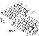
- the longitudinal fingers 11 of the robotic comb 10 each have an upper face 11a provided with a plurality of structures 11b, for example notches or extra thickness structures.
- the structures 11b are for example distributed along the longitudinal direction X of the longitudinal fingers 11 and able to wedge in the horizontal plane H the articles A seized during the movement of the robotic comb 10 in the horizontal plane H.
- the means of movement 13 of the robotic comb 10 can for example position the robotic comb 10 so that the upstream end of the robotic comb 10 is placed above the evacuation hole 17, if necessary close from the downstream end of the evacuation hole 17. Then, the means for evacuating defective articles detected 19 can sweep the articles A placed on the robotic comb 10 to cause them to fall into the evacuation hole 17.
- the adjustment and synchronization means 20 can also be connected to the drive motor 9 of the conveyor belt 6, or to a displacement speed sensor of the conveyor belt 6, so as to allow fine adjustment of the speed of movement of the articles A seized, that is to say the speed of movement of the robotic comb 10, with the speed of movement of the conveyor belt 6.
- the means of movement 13 of the robotic comb 10 are then implemented to move the articles A in the vertical direction Z , simultaneously, to bring the articles A to rest on the conveyor belt 6.
- the robotic comb 10 is moved over a fifth path section P5-P6 belonging to an active path section.
- the robotic comb 10 is lowered vertically in the vertical direction Z, relative to the fixed conveyor belt 6, by the means 14 capable of moving the robotic comb 10 in the vertical direction Z, while maintaining the horizontal movement of the articles A synchronized with the speed of movement V of the conveyor belt 6 thanks to the means 15 controlling the robotic comb 10 in the longitudinal direction X.
- the sixth path section thus belongs to an inactive path section of the robotic comb 10, illustrated in dotted lines on the figures 12 to 14 , that is to say a section of path on which the robotic comb does not perform any function of carrying the articles A.
Landscapes
- Engineering & Computer Science (AREA)
- Mechanical Engineering (AREA)
- Attitude Control For Articles On Conveyors (AREA)
- Specific Conveyance Elements (AREA)
Description
L'invention est relative au convoyage d'articles, notamment dans une chaîne de production.The invention relates to the conveying of articles, in particular in a production line.
L'invention s'applique tout spécialement au cas de pots tel que typiquement un pot en matière plastique, en carton paraffiné ou analogue et destiné à être fermé par un opercule. Le terme « pot » doit être compris au sens large comme comprenant les pots à proprement parler, mais également les barquettes, les coupelles, ou toute autre forme d'emballage primaire analogue. Les articles peuvent se présenter sous forme de pots uniques ou de plaquettes individualisées comprenant plusieurs pots côte à côte et attachés les uns aux autres en étant agencés en colonnes et/ou rangées avec entre eux des lignes ou zones frangibles à plus faible résistance. Par exemple, une plaquette peut comporter deux pots ou quatre pots agencés en deux rangées comprenant chacune deux pots ou encore six pots en deux rangées comprenant chacune trois pots...The invention applies most especially to the case of pots such as typically a pot made of plastic, waxed cardboard or the like and intended to be closed by a lid. The term "pot" should be understood in the broad sense as comprising the pots strictly speaking, but also the trays, the cups, or any other similar form of primary packaging. The articles can be in the form of single pots or of individual plates comprising several pots side by side and attached to each other by being arranged in columns and/or rows with between them lines or frangible zones of weaker resistance. For example, a plate can comprise two pots or four pots arranged in two rows each comprising two pots or even six pots in two rows each comprising three pots...
Comme détaillé ci-après, l'invention s'applique au cas de plaquettes séparées mais tout une application toute particulière au cas d'articles sous forme de pots uniques, c'est-à-dire individuellement séparés et n'étant pas liés en plaquettes, lesdits pots uniques étant remplis ou non de contenant et fermés ou non par des opercules.As detailed below, the invention applies to the case of separate wafers but a very particular application to the case of articles in the form of single pots, that is to say individually separated and not being linked in wafers, said single pots being filled or not with a container and closed or not by lids.
Un tel article contient typiquement, ou est typiquement destiné à contenir, un contenu homogène ou non, présentant un état d'ensemble plus ou moins fluide, comportant éventuellement des morceaux plus ou moins solides. Un tel contenu est par exemple un produit lacté ou un dessert, cette liste n'étant pas limitative.Such an article typically contains, or is typically intended to contain, a content that is homogeneous or not, presenting a more or less fluid overall state, possibly including more or less solid pieces. Such content is for example a milk product or a dessert, this list not being exhaustive.
Ainsi par exemple, l'invention trouve notamment une application dans la production de produits laitiers frais ou ultra-frais tels que yaourts et assimilés, crèmes dessert, glaces et assimilés, mais également des produits fromagers, des compotes... L'invention s'applique également dans la production de produits de natures et/ou de destinations différentes mais que l'on peut considérer comme analogues au regard de leur convoyage dans la chaine de production.Thus, for example, the invention finds application in particular in the production of fresh or ultra-fresh dairy products such as yogurts and the like, dessert creams, ice creams and the like, but also cheese products, compotes, etc. The invention s also applies in the production of products of different natures and/or destinations but which can be considered as analogous with regard to their conveyance in the production chain.
Pour la production de tels produits, on dispose ou on fabrique un contenu à emballer, on dispose ou on fabrique des pots et des opercules, individuels ou agencés en plaquettes, on dispose ou on fabrique éventuellement des flans de suremballage individualisés. Puis, on réalise les produits eux-mêmes, c'est-à-dire que l'on emplit les pots avec le ou les contenus souhaités puis on ferme les pots par mise en place des opercules. Puis on forme des lots ou packs et s'ils comprennent plusieurs pots, on assure leur regroupement, par exemple superposition. Puis, on dispose éventuellement autour de chaque pot, lot ou pack un flan de suremballage que l'on plie et que l'on ferme sur lui-même. Puis on encaisse le cas échéant les articles.For the production of such products, a content to be packaged is arranged or manufactured, jars and lids, individual or arranged in blisters, are arranged or manufactured, optionally individualized overwrapping blanks are arranged or manufactured. Then, the products themselves are produced, that is to say that the jars are filled with the desired content(s) and then the jars are closed by placing the lids. Then we form batches or packs and if they include several pots, we ensure their grouping, for example superposition. Then, optionally, around each jar, batch or pack, an overwrapping blank is placed which is folded and closed on itself. Then we cash the items if necessary.
Des machines de convoyages permettent le transport d'articles, c'est-à-dire de produits à divers stades de leur production, entre chacune de ces opérations. On entend notamment par articles d'une chaîne de production, des produits à divers stades de leur production, notamment pots vides, pots emplis de contenu, pots emplis de contenu et fermés, ou encore pots emplis de contenu, fermés et suremballés.Conveying machines allow the transport of articles, that is to say of products at various stages of their production, between each of these operations. The term “items of a production line” is understood to mean in particular products at various stages of their production, in particular empty jars, jars filled with contents, jars filled with contents and closed, or even jars filled with contents, closed and overwrapped.
Une telle machine de convoyage comporte une arrivée d'un lot entrant d'articles séparés, disposés sur, ou dans, un support de lot entrant, et une sortie articles en un lot d'articles sortants.Such a conveying machine comprises an arrival of an incoming batch of separate articles, placed on, or in, an incoming batch support, and an exit of articles into a batch of outgoing articles.
On connait à ce titre des machines de convoyages comportant un tapis de convoyage sur lequel les articles sont poussés, le tapis de convoyage permettant de déplacer les articles d'un emplacement d'opération à l'emplacement d'opération suivant. De tels dispositifs de convoyage présentent l'inconvénient de perdre, au cours du convoyage, les informations sur la position relative et l'orientation relative des articles.Conveying machines are known in this respect comprising a conveyor belt on which the articles are pushed, the conveyor belt making it possible to move the articles from one operating location to the next operation location. Such conveying devices have the drawback of losing, during conveying, the information on the relative position and the relative orientation of the articles.
Ces informations sont essentielles dans de nombreux cas pour le traitement postérieur des articles, par exemple pour la fermeture des pots, l'alignement des décors, l'assemblage en lot ou pack, le suremballage ou encore l'encaissage des articles. Il est alors nécessaire de mettre en place des moyens de détection de position et d'orientation des articles et des moyens de repositionnement et/ou de recalage d'orientation, en aval de telles machines de convoyage, ce qui est complexe et couteux.This information is essential in many cases for the subsequent processing of articles, for example for closing jars, aligning decorations, assembling in batches or packs, over-packaging or even case-packing articles. It is then necessary to set up means for detecting the position and orientation of the articles and means for repositioning and/or resetting the orientation, downstream of such conveying machines, which is complex and costly.
On entend ici par « informations sur la position relative » une connaissance de la position d'un article par rapport à des articles adjacents et/ou par rapport à un référentiel général. On entend notamment une information sur la position dudit article dans un plan horizontal de la machine de convoyage, notamment un plan de déplacement général des articles à convoyer.The term “information on the relative position” is understood here to mean knowledge of the position of an article with respect to adjacent articles and/or with respect to a general reference system. This means in particular information on the position of said article in a horizontal plane of the conveying machine, in particular a plane of general movement of the articles to be conveyed.
On entend également par « informations sur l'orientation relative » une connaissance de l'orientation d'un article par rapport à des articles adjacent et/ou par rapport à un référentiel général. On entend notamment une information sur l'orientation dudit article selon un axe vertical perpendiculaire audit plan horizontal de la machine de convoyage.The term “information on the relative orientation” also means knowledge of the orientation of an article with respect to adjacent articles and/or with respect to a general reference system. This means in particular information on the orientation of said article along a vertical axis perpendicular to said horizontal plane of the conveying machine.
On connait par ailleurs des convoyeurs dits « à pas de pèlerin » qui permettent de déplacer des articles pas-à-pas en conservant au moins des informations sur la position relative des articles, et éventuellement également sur l'orientation relative des articles, telles qu'indiquées ci-dessus. De tels convoyeurs comportent usuellement une succession de barres montées sur des arbres à cames qui en venant successivement soulever les articles permettent leur avancée, pas-à-pas, le long du convoyeur. De tels convoyeurs à « pas de pèlerin » présentent l'inconvénient d'être onéreux, car composés d'un grand nombre de pièces en mouvement synchronisé, et d'être usuellement limités au transport de pots individuels.Also known are so-called “pilgrim step” conveyors which make it possible to move articles step by step while retaining at least information on the relative position of the articles, and possibly also on the relative orientation of the articles, such as indicated above. Such conveyors usually comprise a succession of bars mounted on camshafts which, by successively lifting the articles, allow them to advance, step by step, along the conveyor. Such “pilgrim step” conveyors have the drawback of being expensive, since they consist of a large number of parts in synchronized movement, and of being usually limited to the transport of individual pots.
Le document
Le problème à la base de l'invention est de donc proposer un procédé et une machine de convoyage qui permettent de conserver une information sur la position relative et l'orientation relative des articles lors du convoyage de sorte à permettre un traitement aval des articles sans repositionnement préliminaire. L'invention vise également à proposer un tel procédé et une telle machine de convoyage qui soient peu couteux et aisément adaptables.The problem underlying the invention is therefore to propose a method and a conveying machine which make it possible to keep information on the relative position and the relative orientation of the articles during the conveying so as to allow downstream processing of the articles without preliminary repositioning. The invention also aims to provide such a method and such a conveying machine which are inexpensive and easily adaptable.
A cet effet, et selon un premier aspect, l'invention a pour objet un procédé de convoyage d'articles dans une chaîne de production, dans lequel,
- on dispose d'un lot entrant d'articles comportant une pluralité d'articles séparés, disposés sur, ou dans, un support de lot entrant de sorte à être alignés selon un plan horizontal en une ou plusieurs colonnes longitudinales et/ou une ou plusieurs rangées transversales,
- on déplace la pluralité d'articles du lot entrant par rapport au support de lot entrant, de manière simultanée, selon une direction verticale perpendiculaire au plan horizontal, en conservant les articles immobiles par rapport au support de lot entrant dans le plan horizontal, de sorte à ce que les articles ne soient plus en contact avec le support de lot entrant et soient libres d'être déplacés dans le plan horizontal sans toucher le support de lot entrant,
- on amène les articles saisis à la verticale d'un tapis de convoyage horizontal, les articles étant espacés verticalement dudit tapis de convoyage par un espacement vertical prédéfini,
- puis, on déplace les articles dans la direction verticale, de manière simultanée, pour amener les articles à reposer sur le tapis de convoyage, et
- on évacue les articles en un lot d'articles sortants au moyen du tapis de convoyage.
- an incoming batch of articles is provided comprising a plurality of separate articles, arranged on, or in, an incoming batch support so as to be aligned along a horizontal plane in one or more longitudinal columns and/or one or more cross rows,
- the plurality of items of the incoming batch are moved with respect to the incoming batch support, simultaneously, in a vertical direction perpendicular to the horizontal plane, keeping the items immobile with respect to the incoming batch support in the horizontal plane, so that the articles are no longer in contact with the incoming batch support and are free to be moved in the horizontal plane without touching the incoming batch support,
- the seized articles are brought vertically to a horizontal conveyor belt, the articles being spaced vertically from said conveyor belt by a predefined vertical spacing,
- then, the articles are moved in the vertical direction, simultaneously, to bring the articles to rest on the conveyor belt, and
- the articles are evacuated in a batch of outgoing articles by means of the conveyor belt.
Selon une caractéristique de ce procédé :
- lorsque les articles sont amenés à la verticale du tapis de convoyage, le tapis de convoyage présente un déplacement selon une direction de déplacement du plan horizontal avec une vitesse de déplacement,
- les articles saisis étant à la verticale du tapis de convoyage, on règle et on synchronise avec ladite vitesse de déplacement du tapis de convoyage un déplacement horizontal des articles, et
- on déplace les articles dans la direction verticale pour amener les articles à reposer sur le tapis de convoyage en conservant le déplacement horizontal des articles synchronisé avec la vitesse de déplacement du tapis de convoyage.
- when the articles are brought to the vertical of the conveyor belt, the conveyor belt has a movement in a direction of movement of the horizontal plane with a speed of movement,
- the seized articles being vertical to the conveyor belt, a horizontal movement of the articles is regulated and synchronized with said speed of movement of the conveyor belt, and
- the articles are moved in the vertical direction to bring the articles to rest on the conveyor belt while keeping the horizontal movement of the articles synchronized with the speed of movement of the conveyor belt.
Selon une réalisation, les articles du lot entrant sont disposés, sur, ou dans, le support de lot entrant, en colonnes longitudinales régulièrement alignées de sorte à présenter un pas transversal prédéfini selon une direction transversale du plan horizontal, et à être espacées les unes des autres selon ladite direction transversale par des espacements transversaux de préhension.According to one embodiment, the items of the incoming batch are arranged, on or in the incoming batch support, in regularly aligned longitudinal columns so as to have a predefined transverse pitch in a transverse direction of the horizontal plane, and to be spaced apart others in said transverse direction by transverse gripping spaces.
Selon une réalisation, pour déplacer la pluralité d'articles du lot entrant, de manière simultanée, selon la direction verticale, on vient introduire dans les espacements transversaux de préhension du lot entrant des doigts longitudinaux d'un peigne robotisé, lesdits doigts longitudinaux étant régulièrement alignés de sorte à présenter ledit pas transversal prédéfini, et étant agencés de telle sorte que deux doigts longitudinaux voisins sont aptes à entourer transversalement les articles d'une colonne longitudinale d'articles du lot entrant et à soutenir les articles de ladite colonne longitudinale pour les saisir et les amener à la verticale du tapis de convoyage.According to one embodiment, to move the plurality of articles of the incoming batch, simultaneously, in the vertical direction, longitudinal fingers of a robotic comb are introduced into the transverse spacings for gripping the incoming batch, said longitudinal fingers being regularly aligned so as to have said predefined transverse pitch, and being arranged such that two adjacent longitudinal fingers are able to transversely surround the articles of a longitudinal column of articles of the incoming batch and to support the articles of said longitudinal column for them seize and bring them to the vertical of the conveyor belt.
Selon une réalisation, les articles comportent au moins une portion d'extension inférieure et une portion supérieure, la portion supérieure présentant un encombrement transversal supérieur à un encombrement transversal de la portion d'extension inférieure, et, pour déplacer les articles du lot entrant selon une direction verticale, on vient contacter par en dessous la portion supérieure en entourant transversalement la portion inférieure.According to one embodiment, the articles comprise at least a lower extension portion and an upper portion, the upper portion having a transverse dimension greater than a transverse dimension of the lower extension portion, and, to move the articles of the incoming batch according to a vertical direction, the upper portion is contacted from below by surrounding the lower portion transversely.
Selon une réalisation, les articles sont du type comportant un corps avec une paroi de fond, une paroi latérale fermée sur elle-même et une fermeture de dessus, ainsi qu'une collerette vers la fermeture de dessus, ledit corps constituant la portion d'extension inférieure, ladite collerette constituant la portion supérieure.According to one embodiment, the articles are of the type comprising a body with a bottom wall, a side wall closed on itself and a top closure, as well as a flange towards the top closure, said body constituting the portion of lower extension, said flange constituting the upper portion.
Selon une réalisation, on contacte les articles uniquement par en-dessous, selon une direction verticale.According to one embodiment, the articles are contacted only from below, in a vertical direction.
Selon une réalisation, pour déplacer les articles du lot entrant selon une direction verticale, on monte verticalement un peigne robotisé, par rapport au support de lot entrant horizontal, en maintenant le peigne robotisé horizontal, de sorte à venir contacter, et soulever du support de lot entrant, les articles du lot entrant. Selon une réalisation, pour déplacer les articles du lot entrant selon une direction verticale, on abaisse verticalement, par rapport à un peigne robotisé horizontal, le support de lot entrant sur, ou dans, lequel sont disposés les articles, en maintenant ledit support de lot entrant horizontal, de sorte à venir faire reposer les articles du lot entrant sur le peigne robotisé.According to one embodiment, to move the articles of the incoming batch in a vertical direction, a robotic comb is mounted vertically, relative to the horizontal incoming batch support, while maintaining the robotic comb horizontal, so as to come into contact, and lift from the support of incoming batch, the items of the incoming batch. According to one embodiment, to move the articles of the incoming batch in a vertical direction, the incoming batch support is lowered vertically, relative to a horizontal robotic comb, on or in which the articles are arranged, while maintaining said batch support incoming horizontal, so as to rest the articles of the incoming batch on the robotic comb.
Selon une réalisation, pour déplacer les articles du lot entrant selon une direction verticale, on déplace un peigne robotisé et/ou le support de lot entrant de sorte à ce que le peigne robotisé et le support de lot entrant présentent une vitesse verticale relative inférieure à 200 millimètres par secondes lors d'un contact entre le peigne robotisé et les articles du lot entrant.According to one embodiment, to move the articles of the incoming batch in a vertical direction, a robotic comb and/or the incoming batch support is moved so that the robotic comb and the incoming batch support have a relative vertical speed less than 200 millimeters per second during contact between the robotic comb and the articles of the incoming batch.
Selon une réalisation, on déplace un peigne robotisé, sur un tronçon de cheminement actif pour amener les articles à la verticale du tapis de convoyage, avec une première vitesse de déplacement dans le plan horizontal, et sur un tronçon de cheminement inactif de retour, dans lequel le peigne robotisé n'assure aucune fonction de portage des articles, avec une seconde vitesse de déplacement dans le plan horizontal supérieure à la première vitesse de déplacement.According to one embodiment, a robotic comb is moved, on an active path section to bring the articles vertically to the conveyor belt, with a first speed of movement in the horizontal plane, and on an inactive return path section, in wherein the robotic comb performs no function of carrying the articles, with a second speed of movement in the horizontal plane greater than the first speed of movement.
Selon une réalisation, pour déplacer les articles dans la direction verticale pour amener les articles à reposer sur le tapis de convoyage, on abaisse verticalement un peigne robotisé, par rapport au tapis de convoyage fixe, de sorte à venir faire reposer les articles sur le tapis de convoyage.According to one embodiment, to move the articles in the vertical direction to bring the articles to rest on the conveyor belt, a robotic comb is lowered vertically, relative to the fixed conveyor belt, so as to bring the articles to rest on the belt conveying.
Selon une réalisation, pour amener les articles à reposer sur le tapis de convoyage on abaisse verticalement le peigne robotisé par rapport au tapis de convoyage sur une course verticale supérieure à l'espacement vertical prédéfini, de sorte à ce que les articles perdent contact avec le peigne robotisé à la fin de ladite course verticale.According to one embodiment, to bring the articles to rest on the conveyor belt, the robotic comb is lowered vertically relative to the conveyor belt over a vertical travel greater than the predefined vertical spacing, so that the articles lose contact with the robotic comb at the end of said vertical stroke.
Selon une réalisation, pour évacuer les articles en un lot d'articles sortants au moyen du tapis de convoyage, on guide les articles sur le tapis de convoyage dans la direction de déplacement du plan horizontal, notamment au moyen de doigts longitudinaux d'un peigne robotisé entourant transversalement les articles.According to one embodiment, to evacuate the articles in a batch of outgoing articles by means of the conveyor belt, the articles are guided on the conveyor belt in the direction of movement of the horizontal plane, in particular by means of longitudinal fingers of a comb robotic transversely surrounding the articles.
Selon une réalisation, on déplace un peigne robotisé uniquement selon la direction verticale et selon une direction horizontale, la direction horizontale étant en particulier la direction de déplacement du tapis de convoyage.According to one embodiment, a robotic comb is moved only in the vertical direction and in a horizontal direction, the horizontal direction being in particular the direction of movement of the conveyor belt.
Selon une réalisation, alors qu'on amène les articles saisis à la verticale du tapis de convoyage, on mesure au moins une caractéristique physique des articles saisis.According to one embodiment, while the seized articles are brought vertically on the conveyor belt, at least one physical characteristic of the seized articles is measured.
Selon une réalisation, on détermine la présence ou l'absence d'articles défectueux parmi les articles saisis, à partir de la caractéristique physique mesurée, et si on détermine la présence d'articles défectueux parmi les articles saisis, on évacue les articles saisis.According to one embodiment, the presence or absence of defective articles among the seized articles is determined from the measured physical characteristic, and if the presence of defective articles among the seized articles is determined, the seized articles are evacuated.
Selon une réalisation, les articles du lot d'articles sortants présentent, dans le plan horizontal, les mêmes orientations relatives et les mêmes positions relatives que les articles du lot entrant.According to one embodiment, the articles of the batch of outgoing articles have, in the horizontal plane, the same relative orientations and the same relative positions as the articles of the incoming batch.
Selon une réalisation, lorsqu'on règle et on synchronise avec la vitesse de déplacement du tapis de convoyage un déplacement horizontal des articles, on définit une position horizontale des articles du lot d'articles sortants par rapport au tapis de convoyage, en particulier une position horizontal selon la direction de déplacement du tapis de convoyage.According to one embodiment, when a horizontal movement of the articles is regulated and synchronized with the speed of movement of the conveyor belt, a horizontal position of the articles of the batch of outgoing articles is defined with respect to the conveyor belt, in particular a position horizontal according to the direction of movement of the conveyor belt.
Selon une réalisation, lorsqu'on on amène les articles saisis à la verticale d'un tapis de convoyage horizontal, on écarte verticalement desdits articles des déchets de découpe d'articles pour que lesdits déchets de découpe d'articles n'entrent pas en contact avec les articles saisis.According to one embodiment, when the articles are brought vertically from a horizontal conveyor belt, waste from the cutting of articles is separated vertically from the said articles so that the waste from the cutting of articles does not come into contact with the items seized.
Selon une réalisation, on réitère les étapes du procédé une pluralité de fois de sorte à assurer, sur le tapis de convoyage, un flux d'articles sortant comportant des rangées d'articles, transversales à la direction de déplacement du tapis de convoyage, régulièrement espacées par un pas d'espacement longitudinal prédéfini, les articles étant arrangés en une ou plusieurs colonnes.According to one embodiment, the steps of the method are repeated a plurality of times so as to ensure, on the conveyor belt, an outgoing flow of articles comprising rows of articles, transverse to the direction of movement of the conveyor belt, regularly spaced apart by a predefined longitudinal spacing pitch, the articles being arranged in one or more columns.
Selon un deuxième aspect, l'invention a pour objet une machine de convoyage d'articles dans une chaîne de production, pour la mise en œuvre du procédé tel que décrit ci-avant, qui comporte :
- vers l'amont, un support de lot entrant sur, ou dans, lequel sont disposés une pluralité d'articles séparés d'un lot entrant d'articles de sorte à être alignés selon un plan horizontal en une ou plusieurs colonnes longitudinales et/ou une ou plusieurs rangées transversales,
- vers l'aval, un tapis de convoyage horizontal pour évacuer les articles en un lot d'articles sortants,
- vers l'amont, des moyens pour déplacer la pluralité d'articles du lot entrant, de manière simultanée, selon une direction verticale perpendiculaire au plan horizontal, en conservant les articles immobiles par rapport au support de lot entrant dans le plan horizontal, de sorte à ce que les articles ne soient plus en contact avec le support de lot entrant et soient libres d'être déplacés dans le plan horizontal sans toucher le support de lot entrant,
- vers l'aval, des moyens pour amener les articles saisis à la verticale du tapis de convoyage, les articles étant espacés verticalement dudit tapis de convoyage par un espacement vertical prédéfini,
- vers l'aval, des moyens pour déplacer les articles dans la direction verticale, de manière simultanée, pour amener les articles à reposer sur le tapis de convoyage.
- upstream, an incoming batch support on or in which are arranged a plurality of separate articles of an incoming batch of articles so as to be aligned along a horizontal plane in one or more longitudinal columns and/or one or more transverse rows,
- downstream, a horizontal conveyor belt to evacuate the articles in a batch of outgoing articles,
- upstream, means for moving the plurality of articles of the incoming batch, simultaneously, in a vertical direction perpendicular to the horizontal plane, keeping the articles stationary with respect to the incoming batch support in the horizontal plane, so that the articles are no longer in contact with the incoming batch support and are free to be moved in the horizontal plane without touching the incoming batch support,
- downstream, means for bringing the seized articles vertically to the conveyor belt, the articles being spaced vertically from said conveyor belt by a predefined vertical spacing,
- downstream, means for moving the articles in the vertical direction, simultaneously, to bring the articles to rest on the conveyor belt.
Selon une caractéristique d'une telle machine :
- le tapis de convoyage présente un déplacement selon une direction de déplacement du plan horizontal avec une vitesse de déplacement au moins lorsque les articles sont amenés à la verticale du tapis de convoyage,
- la machine comporte en outre vers l'aval, des moyens de réglage et de synchronisation avec la vitesse de déplacement du tapis de convoyage, d'un déplacement horizontal des articles amenés à la verticale du tapis de convoyage, et
- les moyens pour déplacer les articles dans la direction verticale pour amener les articles à reposer sur le tapis de convoyage sont apte à déplacer lesdits articles dans la direction verticale en conservant le déplacement horizontal des articles synchronisé avec la vitesse de déplacement du tapis de convoyage.
- the conveyor belt has a movement in a direction of movement of the horizontal plane with a speed of movement at least when the articles are brought vertically to the conveyor belt,
- the machine further comprises, downstream, means for adjusting and synchronizing with the speed of movement of the conveyor belt, of a horizontal movement of the articles brought to the vertical of the conveyor belt, and
- the means for moving the articles in the vertical direction to bring the articles to rest on the conveyor belt are able to move said articles in the vertical direction while keeping the horizontal movement of the articles synchronized with the speed of movement of the conveyor belt.
Selon une réalisation, les moyens pour amener les articles saisis à la verticale du tapis de convoyage, comportent un peigne robotisé et des moyens de déplacement du peigne robotisé.According to one embodiment, the means for bringing the items seized vertically from the conveyor belt, comprise a robotic comb and means for moving the robotic comb.
Selon une réalisation, le peigne robotisé est muni de doigts longitudinaux régulièrement alignés de sorte à présenter un pas transversal prédéfini selon une direction transversale du plan horizontal perpendiculaire à la direction de déplacement du tapis de convoyage, et agencés de telle sorte que deux doigts longitudinaux voisins sont aptes à entourer transversalement les articles d'une colonne longitudinale d'articles du lot entrant et à soutenir les articles de ladite colonne longitudinale pour les saisir et les amener à la verticale du tapis de convoyage.According to one embodiment, the robotic comb is provided with longitudinal fingers that are regularly aligned so as to have a predefined transverse pitch in a transverse direction of the horizontal plane perpendicular to the direction of movement of the conveyor belt, and arranged in such a way that two neighboring longitudinal fingers are capable of transversely surrounding the articles of a longitudinal column of articles of the incoming batch and of supporting the articles of said longitudinal column in order to grasp them and bring them vertically to the conveyor belt.
Selon une réalisation, le support de lot entrant comporte une pluralité de rainures longitudinales régulièrement alignées avec un pas transversal prédéfini selon une direction transversale du plan horizontal perpendiculaire à la direction de déplacement du tapis de convoyage, lesdites rainures longitudinales étant aptes à accueillir les doigts longitudinaux du peigne robotisé.According to one embodiment, the incoming batch support comprises a plurality of longitudinal grooves regularly aligned with a predefined transverse pitch according to a transverse direction of the horizontal plane perpendicular to the direction of movement of the conveyor belt, said longitudinal grooves being capable of receiving the longitudinal fingers of the robotic comb.
Selon une réalisation, le tapis de convoyage comporte une pluralité de bandes de convoyages, synchronisées, alignées avec un pas transversal prédéfini selon la direction transversale perpendiculaire à la direction de déplacement du tapis de convoyage, et espacées les unes des autres selon la direction transversale par des espacements transversaux de bandes aptes à accueillir les doigts longitudinaux du peigne robotisé.According to one embodiment, the conveyor belt comprises a plurality of conveyor belts, synchronized, aligned with a predefined transverse pitch in the transverse direction perpendicular to the direction of movement of the conveyor belt, and spaced from each other in the transverse direction by transverse spacings of bands able to accommodate the longitudinal fingers of the robotic comb.
Selon une réalisation, les doigts longitudinaux du peigne robotisé présentent chacun une face supérieure munie d'une pluralité de structures, réparties le long de la direction longitudinale des doigts longitudinaux.According to one embodiment, the longitudinal fingers of the robotic comb each have an upper face provided with a plurality of structures, distributed along the longitudinal direction of the longitudinal fingers.
Selon une réalisation, le peigne robotisé comprend un châssis sur lequel sont montés les doigts longitudinaux et un corps de peigne solidaire des moyens de déplacement, le châssis et le corps de peigne étant fixés ensemble par des moyens d'assemblage amovible.According to one embodiment, the robotic reed comprises a frame on which the longitudinal fingers are mounted and a reed body integral with the displacement means, the frame and the reed body being fixed together by removable assembly means.
Selon une réalisation, les moyens d'assemblage amovible sont des moyens d'assemblage magnétique comprenant un premier élément monté sur le corps de peigne et un second élément monté sur le châssis, les moyens d'assemblage amovible étant adaptés pour fixer le châssis sur le corps de peigne de manière amovible en réponse à une sollicitation suffisamment importante pour surmonter une force d'attraction magnétique prédéfinie entre le premier élément et le second élément.According to one embodiment, the removable assembly means are magnetic assembly means comprising a first element mounted on the reed body and a second element mounted on the frame, the removable assembly means being adapted to fix the frame on the comb body removably in response to a sufficiently large stress to overcome a predefined magnetic attraction force between the first element and the second element.
Selon une réalisation, les moyens de déplacement comportent des moyens de déplacement du peigne robotisé selon une direction horizontale contrôlés par les moyens de réglage et de synchronisation avec la vitesse de déplacement du tapis de convoyage, lesdits moyens comportant notamment un moteur linéaire, par exemple sous forme de vérin magnétique.According to one embodiment, the moving means comprise means for moving the robotic reed in a horizontal direction controlled by the means for adjustment and synchronization with the speed of movement of the conveyor belt, said means comprising in particular a linear motor, for example under form of magnetic cylinder.
Selon une réalisation, les moyens de déplacement comportent des moyens de déplacement du peigne robotisé selon la direction verticale aptes à déplacer le peigne robotisé en conservant les doigts longitudinaux du peigne robotisé horizontaux, lesdits moyens comportant notamment un ensemble à excentriques.According to one embodiment, the moving means comprise means for moving the robotic comb in the vertical direction capable of moving the robotic comb while keeping the longitudinal fingers of the robotic comb horizontal, said means comprising in particular an eccentric assembly.
Selon une réalisation, la machine comporte en outre des moyens de mesure d'au moins une caractéristique physique des articles saisis.According to one embodiment, the machine further comprises means for measuring at least one physical characteristic of the seized articles.
Selon une réalisation, la machine comporte en outre des moyens de détermination aptes à déterminer la présence ou l'absence d'articles défectueux parmi les articles saisis à partir de ladite caractéristique physique des articles saisis et des moyens d'évacuation d'articles détectés défectueux.According to one embodiment, the machine further comprises determination means suitable for determining the presence or absence of defective articles among the seized articles from said physical characteristic of the seized articles and means for evacuating defective articles detected .
Selon une réalisation, les moyens d'évacuation d'articles détectés défectueux comprennent un trou d'évacuation séparant le tapis de convoyage du support de lot entrant, dans le plan horizontal, les moyens d'évacuation d'articles détectés défectueux étant aptes à évacuer par le trou d'évacuation les articles défectueux parmi les articles saisis.According to one embodiment, the means for evacuating defective detected articles comprise an evacuation hole separating the conveyor belt from the incoming batch support, in the horizontal plane, the means for evacuating defective detected articles being capable of evacuating through the evacuation hole the defective articles among the seized articles.
Selon une réalisation, le support de lot entrant comporte une pluralité de support de pots d'un outil de découpe d'une chaine de production.According to one embodiment, the incoming batch support comprises a plurality of support pots of a cutting tool of a production line.
Selon une réalisation, la pluralité de structures est adaptée pour écarter verticalement des articles saisis, de déchets de découpe d'articles, lors d'un mouvement du peigne robotisé.According to one embodiment, the plurality of structures is adapted to vertically separate seized articles, of article cutting waste, during a movement of the robotic comb.
De cette façon, le procédé et la machine de convoyage conservent une information sur la position relative et l'orientation relative des articles lors du convoyage. Il est ainsi possible de mettre en œuvre, sans repositionnement préliminaire, une grande variété de traitements avals des articles, et notamment une fermeture des articles, un alignement et une disposition de décors sur les articles, un assemblage en lot ou pack des articles, un suremballage des articles. En outre, ceci est obtenu moyennant une machinabilité élevée pour de hautes cadences, de façon sûre avec une ligne de fabrication qui évite les complexités pénalisantes. Par ailleurs, il est possible de mesurer des caractéristiques physiques des articles au cours du convoyage et d'évacuer des articles déterminés comme défectueux au vue desdites caractéristiques physiques mesurées.In this way, the method and the conveying machine keep information on the relative position and the relative orientation of the articles during the conveying. It is thus possible to implement, without preliminary repositioning, a wide variety of downstream processing of the articles, and in particular a closing of the articles, an alignment and an arrangement of decorations on the articles, an assembly in batch or pack of the articles, a overpacking of items. In addition, this is obtained by means of high machinability for high speeds, in a safe way with a production line that avoids penalizing complexities. Furthermore, it is possible to measure the physical characteristics of the articles during conveying and to evacuate articles determined to be defective in view of said measured physical characteristics.
On décrit maintenant brièvement les figures des dessins.The figures of the drawings will now be briefly described.
On décrit maintenant plusieurs modes de réalisation de l'invention à l'aide des dessins, dans lesquels :
- La
figure 1 est une vue d'ensemble partielle, en perspective d'une machine de convoyage selon un mode de réalisation de l'invention. - La
figure 2 est une vue latérale de la machine de lafigure 1 , illustrant notamment le peigne robotisé, ses moyens de déplacement et le tapis de convoyage. - La
figure 3 est une vue de dessus de la machine de lafigure 1 , illustrant notamment les articles d'un lot entrant, le peigne robotisé et le tapis de convoyage. - La
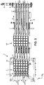
figure 4 est une vue de détail partielle, en coupe d'un outil de découpe d'une chaine de production accueillant des supports de pots d'une machine de convoyage selon un mode de réalisation de l'invention. - La
figure 5 est une vue de détail en perspective partielle du peigne robotisé, illustrant notamment les doigts longitudinaux du peigne. - La
figure 6A est une vue latérale en coupe du peigne robotisé de lafigure 5 illustrant les moyens d'assemblage magnétique, - La
figure 6B est une vue latérale en coupe du peigne robotisé de lafigure 5 , notamment lorsqu'un effort appliqué sur les doigts longitudinaux selon la direction longitudinale est supérieure à une force d'attraction magnétique prédéfinie entre le premier élément et le second élément des moyens d'assemblage magnétique, - La
figure 6C est une vue latérale en coupe du peigne robotisé de lafigure 5 , notamment lorsque le châssis est séparé du corps de peigne, - La
figure 7 est une vue de détail en perspective de la partie amont de la machine illustrant le support de lot entrant de la machine ainsi qu'un lot entrant d'articles. - La
figure 8 est une vue de face en coupe vertical de la partie amont de la machine, les doigts longitudinaux du peigne robotisé étant accueillis dans les rainures longitudinales du support de lot entrant, les articles du lot entrant étant disposés dans le support de lot entrant. - La
figure 9 est une vue partielle latérale de la machine, le peigne robotisé ayant saisi et amené les articles à la verticale du tapis de convoyage. - La
figure 10 est une vue de détail en perspective de la partie amont de la machine, illustrant la grille de plastique des déchets de découpe ainsi que les doigts longitudinaux du peigne robotisé et en particulier les structures de la face supérieure des doigts longitudinaux soutenant, et éloignant des articles, la grille de plastique des déchets de découpe, - La
figure 11 est une vue partielle latérale de la machine, le peigne robotisé ayant déplacé les articles amenés à la verticale du tapis de convoyage pour les faire reposer sur le tapis de convoyage. - La
figure 12 est une courbe illustrant le cheminement du peigne robotisé dans la direction longitudinale au cours de la mise en œuvre d'un procédé selon l'invention. - La
figure 13 est une courbe illustrant la vitesse selon la direction longitudinale du peigne robotisé pendant le cheminement dudit peigne robotisé au cours de la mise en œuvre d'un procédé selon l'invention. - La
figure 14 est une courbe illustrant le cheminement du peigne robotisé dans la direction verticale au cours de la mise en œuvre d'un procédé selon l'invention, - La
figure 15 est un organigramme de fonctionnement d'un mode de réalisation d'une machine selon l'invention.
- The
figure 1 is a partial overall view, in perspective, of a conveying machine according to one embodiment of the invention. - The
picture 2figure 1 , illustrating in particular the robotic comb, its means of movement and the conveyor belt. - The
picture 3figure 1 , illustrating in particular the articles of an incoming batch, the robotic comb and the conveyor belt. - The
figure 4 is a partial detail view, in section, of a cutting tool of a production line accommodating pot supports of a conveying machine according to one embodiment of the invention. - The
figure 5 is a detail view in partial perspective of the robotic comb, illustrating in particular the longitudinal fingers of the comb. - The
Figure 6A is a cross-sectional side view of the robotic comb of thefigure 5 illustrating the magnetic assembly means, - The
figure 6B is a cross-sectional side view of the robotic comb of thefigure 5 , in particular when a force applied to the longitudinal fingers in the longitudinal direction is greater than a predefined magnetic attraction force between the first element and the second element of the magnetic assembly means, - The
Fig. 6C is a cross-sectional side view of the robotic comb of thefigure 5 , in particular when the frame is separated from the comb body, - The
figure 7 is a perspective detail view of the upstream part of the machine illustrating the incoming batch support of the machine as well as an incoming batch of articles. - The
figure 8 is a vertical sectional front view of the upstream part of the machine, the longitudinal fingers of the robotic comb being accommodated in the longitudinal grooves of the incoming batch support, the articles of the incoming batch being arranged in the incoming batch support. - The
figure 9 is a partial side view of the machine, the robotic comb having picked up and brought the articles vertically to the conveyor belt. - The
figure 10 is a detail view in perspective of the upstream part of the machine, illustrating the plastic grid of the cutting waste as well as the longitudinal fingers of the robotic comb and in particular the structures of the upper face of the longitudinal fingers supporting, and moving away from the articles , the plastic grid of cutting waste, - The
figure 11 is a partial side view of the machine, the robotic comb having moved the articles brought vertically from the conveyor belt to make them rest on the conveyor belt. - The
figure 12 is a curve illustrating the path of the robotic comb in the longitudinal direction during the implementation of a method according to the invention. - The
figure 13 is a curve illustrating the speed in the longitudinal direction of the robotic comb during the progress of said robotic comb during the implementation of a method according to the invention. - The
figure 14 is a curve illustrating the progress of the robotic comb in the vertical direction during the implementation of a method according to the invention, - The
figure 15 is an operating flowchart of one embodiment of a machine according to the invention.
Ci-après un exposé détaillé de plusieurs modes de réalisation de l'invention assorti d'exemples et de référence aux dessins.Below is a detailed description of several embodiments of the invention accompanied by examples and reference to the drawings.
L'invention est relative au convoyage d'articles A entre différents postes de traitement d'une chaine de production. Les articles A sont typiquement des produits à divers stades de leur production comportant alors au moins un emballage primaire tel qu'un pot en matière plastique, en carton paraffiné ou analogue destiné à être fermé par un opercule. Les pots à divers stades de leur production sont ainsi vides ou bien emplis de contenu ou encore emplis de contenu et fermé, voire emplis de contenu, fermés et suremballés. Tout cela n'est qu'exemplatif et non limitatif et le terme « article » signifie par convention un produit d'une chaîne de production à un stade de sa production.The invention relates to the conveying of articles A between different processing stations of a production line. Articles A are typically products at various stages of their production then comprising at least one primary packaging such as a pot made of plastic, waxed cardboard or the like intended to be closed by a lid. The pots at various stages of their production are thus empty or else filled with content or even filled with content and closed, or even filled with content, closed and over-packaged. All this is only illustrative and not limiting and the term "article" means by convention a product of a production line at a stage of its production.
Dans une réalisation typique, les articles A ont une forme générale cylindrique ou prismatique ou pseudo cylindrique ou pseudo prismatique ou ovoïde ou analogue avec un axe disposé normalement verticalement. Dans une réalisation typique, un tel article A a une longueur axiale de l'ordre de quelques centimètres.In a typical embodiment, the articles A have a generally cylindrical or prismatic or pseudo-cylindrical or pseudo-prismatic or ovoid or similar shape with an axis normally arranged vertically. In a typical embodiment, such an article A has an axial length of the order of a few centimeters.
Le procédé peut être mis en œuvre et la machine peut fonctionner à condition de disposer d'un lot entrant L d'articles A.The method can be implemented and the machine can operate provided that an incoming batch L of articles A is available.
Un tel lot entrant L comporte une pluralité d'articles A séparés. Dans la présente description, un lot d'articles, notamment un lot entrant L et un lot sortant S comprend au moins un, préférentiellement au moins deux articles A.Such an incoming batch L comprises a plurality of separate articles A. In the present description, a batch of articles, in particular an incoming batch L and an outgoing batch S comprises at least one, preferably at least two articles A.
Les articles A du lot entrant L peuvent par exemple se présenter sous forme de pots uniques ou de plaquettes individualisées comprenant plusieurs pots côte à côte et attachés les uns aux autres en étant agencés en colonnes et/ou rangées avec entre eux des lignes ou zones frangibles à plus faible résistance. Une plaquette peut comporter deux pots ou quatre pots agencés en deux rangées comprenant chacune deux pots ou encore six pots en deux rangées comprenant chacune trois pots... tout cela n'étant donné qu'à titre exemplatif et non limitatif. Préférentiellement, les articles A du lot entrant L se présentent sous la forme de pots uniques.The articles A of the incoming batch L can for example be in the form of single pots or individualized plates comprising several pots side by side and attached to each other by being arranged in columns and/or rows with frangible lines or zones between them at lower resistance. A wafer may comprise two pots or four pots arranged in two rows each comprising two pots or even six pots in two rows each comprising three pots... all this being given only by way of example and not limitation. Preferably, the articles A of the incoming batch L are in the form of single pots.
En particulier le procédé selon l'invention peut être mis en œuvre et la machine selon l'invention peut être installée en aval, notamment immédiatement en aval ou quasiment immédiatement en aval, d'une ligne ou d'une unité d'élaboration des articles A (thermoformage et découpe des pots, et éventuellement emplissage et fermeture des pots).In particular, the method according to the invention can be implemented and the machine according to the invention can be installed downstream, in particular immediately downstream or almost immediately downstream, of a line or of a unit for producing articles. A (thermoforming and cutting of pots, and possibly filling and closing of pots).
Les articles A du lot entrant L sont disposés sur, ou dans, un support de lot entrant 2 de sorte à être alignés selon un plan horizontal H en une ou plusieurs colonnes longitudinales C et/ou une ou plusieurs rangées transversales, perpendiculaire aux colonnes longitudinales.The articles A of the incoming batch L are arranged on, or in, an
En aval, un tapis de convoyage 6 évacue les articles A en un lot d'articles sortants S.Downstream, a
Le procédé et la machine selon l'invention visent à ce que les articles A soient également disposés sur le tapis de convoyage de sorte à être alignés selon un plan horizontal H en une ou plusieurs colonnes longitudinales et/ou une ou plusieurs rangées transversales. Plus précisément, le procédé et la machine selon l'invention visent à ce que les articles A du lot d'articles sortants S présentent, dans le plan horizontal H les mêmes orientations relatives et les mêmes positions relatives que les articles du lot entrant L.The method and the machine according to the invention aim to ensure that the articles A are also arranged on the conveyor belt so as to be aligned along a horizontal plane H in one or more longitudinal columns and/or one or more transverse rows. More specifically, the method and the machine according to the invention are intended to ensure that the articles A of the batch of outgoing articles S have, in the horizontal plane H, the same relative orientations and the same relative positions as the articles of the incoming batch L.
En se référant tout d'abord aux
Elle s'étend horizontalement selon un plan général horizontal H qui est également un plan du mouvement d'entraînement des parties et organes d'entraînement dont est pourvue la machine, tels que tapis de convoyage ou moyens convoyeur décrits ci-après. La machine 1 peut plus particulièrement s'étendre le long d'une direction longitudinale X du plan horizontal H qui est une direction des flux d'articles A convoyés et en particulier du flux d'articles du lot sortant S.It extends horizontally along a general horizontal plane H which is also a plane of the drive movement of the parts and drive members with which the machine is provided, such as conveyor belts or conveyor means described below. The machine 1 can more particularly extend along a longitudinal direction X of the horizontal plane H which is a direction of the flow of articles A conveyed and in particular of the flow of articles of the outgoing batch S.
Les moyens de convoyage, notamment le tapis de convoyage, et les flux d'articles A sont ainsi en mouvement le long de la direction longitudinale X dans un sens donné, ce qui permet de définir sur la machine un côté amont (coté gauche sur les
Enfin, on définit une direction verticale Z, perpendiculaire au plan horizontal H, et donc perpendiculaire à la direction longitudinale X et à la direction transversale Y. Cette direction verticale Z est orientée dans un sens donné, de sorte à définir, pour les éléments de la machine 1 et les articles A, un « dessus » et un « dessous ». Se manière identique, on définit des parties « inférieures » et des parties « supérieures » pour les éléments de la machine 1 et les articles A, en référence à la direction verticale Z et au sens d'orientation de ladite direction verticale Z.Finally, a vertical direction Z is defined, perpendicular to the horizontal plane H, and therefore perpendicular to the longitudinal direction X and to the transverse direction Y. This vertical direction Z is oriented in a given direction, so as to define, for the elements of machine 1 and articles A, a "top" and a "bottom". In the same way, "lower" parts and "upper" parts are defined for the elements of the machine 1 and the articles A, with reference to the vertical direction Z and to the direction of orientation of said vertical direction Z.
Comme illustré sur les
Comme illustré en particulier sur la
Par « les colonnes longitudinales sont espacées les unes des autres selon la direction transversale par des espacements transversaux de préhension », on entend qu'une portion au moins des articles de chaque colonne longitudinale est espacée d'une portion au moins des articles d'une colonne longitudinale voisine, selon la direction transversale Y, par des espacements transversaux de préhension Ey, illustrés sur la
Ainsi en particulier, les articles A peuvent comporter au moins une portion d'extension inférieure A1 et une portion supérieure A2 comme cela est visible sur la
Par « encombrement transversal » d'un élément, on entend une extension maximale dudit élément selon la direction transversale Y.By "transverse size" of an element is meant a maximum extension of said element in the transverse direction Y.
Ainsi par exemple, les articles A peuvent être des pots comportant un corps constituant la portion d'extension inférieure A1, ledit corps A1 comportant une paroi de fond, une paroi latérale fermée sur elle-même et une fermeture de dessus. Les pots peuvent comporter une collerette, vers la fermeture de dessus, constituant la portion supérieure A2. En variante, les pots peuvent présenter par exemple une forme conique avec une portion d'extension inférieure A1 de plus faible diamètre qu'une portion supérieure A2.Thus, for example, the articles A can be pots comprising a body constituting the lower extension portion A1, said body A1 comprising a bottom wall, a side wall closed on itself and a top closure. The pots may include a flange, towards the top closure, constituting the upper portion A2. Alternatively, the pots may for example have a conical shape with a lower extension portion A1 of smaller diameter than an upper portion A2.
Dans cette réalisation donnée à titre purement exemplaire, les espacements transversaux de préhension Ey entre les colonnes longitudinales C sont ainsi entendus comme des espacements entre les portions d'extension inférieure A1 des articles des colonnes longitudinales C.In this embodiment given purely by way of example, the transverse gripping spacings Ey between the longitudinal columns C are thus understood as spacings between the portions of lower extension A1 of the articles of the longitudinal columns C.
Dans un mode de réalisation illustré en détail sur la
Les supports de pots 3 sont des éléments d'un outil de découpe 4 d'une chaine de production tel qu'illustré sur la
Ainsi, la partie supérieure 28 est apte à descendre par rapport aux supports de pots 3 alors que la matrice inférieure 27 monte par rapport aux supports de pots 3, jusqu'à emprisonner les articles A, portés par les supports de pots 3, et liés par la feuille matériau thermoformée de laquelle sont issus les articles A, pour assurer la coupe et la séparation des articles A de ladite feuille devenant un déchet de découpe.Thus, the
A cette fin, la matrice inférieure 27 comporte par exemple une pluralité d'ouvertures réparties dans le plan horizontal et formant des cavités aptes à accueillir les supports de pots 3 lorsque la matrice inférieure 27 monte par rapport aux supports de pots 3. La partie supérieure 28 de l'outil de découpe 4 porte des couteaux 28a qui sont arrangés pour venir en regard de rainures 27a pratiquées dans la matrice inférieure aux emplacements de découpe souhaités.de sorte à ce que le matériau des articles A soit pris en sandwich entre les couteaux et les rainures pour être découpé. La partie supérieure 28 peut en outre comporter des dévetisseurs 28b pour faciliter l'extraction des articles A après la découpe.To this end, the
Selon les modes de réalisation, l'un parmi la matrice inférieure 27, la partie supérieure 28 et les supports de pots 3 peut par exemple être fixe, notamment les supports de pots 3, tandis que les autres, notamment la matrice inférieure 27 et la partie supérieure 28, peuvent se déplacer selon l'axe vertical.According to the embodiments, one of the
Les supports de pots 3 peuvent être soit fixes, soit animés d'un mouvement vertical descendant permettant d'éloigner la partie supérieure des articles A de la partie supérieure 28 de l'outil de découpe 4 pour faciliter la préhension des articles A sans risque de collision.The pot supports 3 can be either fixed or animated by a downward vertical movement making it possible to move the upper part of the articles A away from the
De cette manière, on éloigne les articles A des déchets de découpe tels que la grille de plastique et de la partie supérieure 28 de l'outil de découpe.In this way, the articles A are kept away from the cutting waste such as the plastic grid and from the
Lorsque les supports de pots 3 sont mobiles, ils ne sont de telle manière à ne pas modifier la position ni l'orientation des articles A.When the pot supports 3 are mobile, they are not in such a way as to modify the position or the orientation of the articles A.
Dans ce mode de réalisation, les supports de pots 3 garantissent ainsi un arrangement des articles A du lot entrant L en colonnes longitudinales C tel que détaillé ci-avant.In this embodiment, the pot supports 3 thus guarantee an arrangement of the articles A of the incoming batch L in longitudinal columns C as detailed above.
Vers l'aval, la machine 1 de convoyage comporte un tapis de convoyage 6 visible sur les
Le déplacement du tapis de convoyage 6 est réalisé avec une vitesse de déplacement V selon la direction longitudinale X.The displacement of the
La vitesse de déplacement V du tapis de convoyage 6 est connue. La vitesse de déplacement peut être prédéfinie et, notamment, constante. La vitesse de déplacement V peut également être modulée, c'est-à-dire non constante. Dans ce cas, la vitesse de déplacement V est avantageusement mesurée en temps réel par un capteur ou par l'intermédiaire d'un moteur d'entraînement du tapis de convoyage. La vitesse de déplacement V du tapis de convoyage 6 peut notamment être modulée pour gérer l'écartement des articles sur le convoyeur et/ou pour répondre à des contraintes d'asservissement amont et/ou aval de la chaîne de production.The displacement speed V of the
Par « déplacement», on entend que ladite au moins une bande convoyage 7 est entraînée en mouvement avec une vitesse de déplacement V non nulle au moins sur une partie d'une période de fonctionnement de la machine de convoyage. En particulier, comme détaillé ci-après, on entend par là notamment que le tapis de convoyage est entraîné en mouvement avec une vitesse V non nulle au moins lorsque des articles A sont amenés à la verticale dudit tapis de convoyage.By "displacement" is meant that said at least one conveying belt 7 is driven in motion with a non-zero displacement speed V at least over part of an operating period of the conveying machine. In particular, as detailed below, this means in particular that the conveyor belt is driven in motion with a non-zero speed V at least when articles A are brought vertically to said conveyor belt.
Par « vitesse de déplacement», on entend ainsi une vitesse linéaire de ladite au moins une bande de convoyage 7 du tapis de convoyage, par exemple dans le référentiel du châssis fixe 8 du tapis de convoyage 6.By "speed of movement" is thus meant a linear speed of said at least one conveyor belt 7 of the conveyor belt, for example in the frame of reference of the fixed
Le tapis de convoyage 6 comporte au moins une bande convoyage 7 montée sur un châssis fixe 8 et entraînée par un moteur d'entraînement 9. Toutefois, le tapis de convoyage 6 peut avantageusement comporter une pluralité de bandes de convoyages 7 synchronisées comme illustré sur la
Par « synchronisées », on entend que les bandes de convoyages 7 présentent une même direction de déplacement D et une même vitesse de déplacement prédéfinie V selon la direction de déplacement D.By "synchronized", it is meant that the conveyor belts 7 have the same direction of movement D and the same predefined speed of movement V in the direction of movement D.
Par extension, on parle de « vitesse de déplacement du tapis de convoyage » en entendant par ceci une vitesse de la, ou des, bande(s) de convoyage 7 du tapis de convoyage 6 par rapport au châssis fixe 8.By extension, we speak of "movement speed of the conveyor belt" meaning by this a speed of the conveyor belt(s) 7 of the
Par ailleurs, la machine de convoyage 1 comporte un peigne robotisé 10 illustré sur les
Sur les
Le peigne robotisé 10 est muni d'une pluralité de doigts longitudinaux 11, s'étendant selon la direction longitudinale X, par exemple de l'aval vers l'amont de la machine de convoyage 1.The
Les doigts longitudinaux 11 sont assemblés de manière fixe en un faisceau de doigts longitudinaux par un châssis 21, de sorte à être solidaires et immobiles les uns par rapport aux autres. Le châssis 21 est fixé, de manière immobile, à un corps de peigne 22 par des moyens d'assemblage amovible 23. Le corps de peigne est, quant à lui, solidaire du reste de la machine de convoyage 1, et notamment solidaire de moyens de déplacement 13 du peigne robotisé 10 tels que détaillés plus loin.The
Grâce aux moyens d'assemblage amovible 23, il est possible de séparer le châssis 21 portant les doigts longitudinaux 11 du corps de peigne 22, de sorte à échanger aisément le faisceau de doigts longitudinaux 11 par un autre faisceau, neuf et/ou de conformation différente, sans avoir à démonter la machine de convoyage. Ce qui permet d'accroître la flexibilité de la machine dans le cas du convoyage d'articles A de tailles différentes par la même machine.Thanks to the removable assembly means 23, it is possible to separate the
Dans un mode de réalisation illustré sur les
Les moyens d'assemblage magnétique comportent un premier élément 24 monté sur le corps de peigne 22 et un second élément 25 monté sur le châssis 21. Le premier élément 24 et le second élément 25 sont tels qu'une force d'attraction magnétique peut exister entre eux lorsque ces éléments sont en proximité. Ainsi par exemple, le premier élément 24 peut comporter un aimant tandis que le second élément 25 comporte une ferrite ou vis-versa. Ladite force d'attraction magnétique peut notamment être suffisamment intense pour solidariser le châssis 21 au corps de peigne 22 en régime normal, c'est-à-dire lorsque les efforts exercées sur le châssis 21 et le corps de peigne 22 ne sont pas top intenses. La force d'attraction magnétique prédéfinie peut ainsi être calibrée par le choix d'un aimant permanent pour le premier élément 24 et/ou le second élément 25, et un réglage d'un entrefer entre le premier élément 24 et le second élément 25, par exemple au moyen de cales pelables.The magnetic assembly means comprises a
Ainsi, comme illustré sur la
Par ailleurs, notamment en cas de choc sur les doigts longitudinaux 11, le châssis 21 portant les doigts longitudinaux 11 peut se séparer corps de peigne 22 sans rupture de pièce mais par une simple séparation du premier élément 24 et du second élément 25, comme illustré sur la
Pour renforcer l'assemblage du châssis 21 et du corps de peigne 22, des positionneurs 26 peuvent permettre de limiter le déplacement relatif du châssis 21 et du corps de peigne 22 dans la direction verticale lorsque ledit châssis 21 et ledit corps de peigne 22 se trouvent en proximité. De cette manière, il est possible de prévenir un déplacement vertical du peigne robotisé 10 dans l'outil de découpe 4 qui pourrait être dommageable à l'outil de découpe.To reinforce the assembly of the
Les positionneurs 26 comportent par exemple des tiges 26a s'étendant à partir du corps de peigne 22 sur un certaine distance et étant aptes à traverser des trous 26b pratiqués dans le châssis 21. Ainsi, les tiges 26a peuvent être orientées selon la direction longitudinale X, comme illustré sur la
Les doigts longitudinaux 11 sont régulièrement alignés de sorte à présenter un pas transversal prédéfini Py identique au pas transversal des articles A disposés sur, ou dans, le support de lot entrant 2. Les doigts longitudinaux 11 présentent avantageusement, sur au moins une portion active desdits doigts longitudinaux 11, un encombrement transversal de doigt Ed inférieur aux espacements transversaux de préhension Ey séparant les colonnes longitudinales C de sorte à pouvoir être introduits entre les colonnes longitudinales C sans toucher les articles A desdites colonnes longitudinales C.The
Le peigne robotisé 10 est par ailleurs arrangé de telle sorte que deux doigts longitudinaux 11 voisins sont aptes à entourer transversalement les articles A d'une colonne longitudinale C et à soutenir les articles A de ladite colonne longitudinale pour les saisir et les amener à la verticale du tapis de convoyage 6.The
On se réfère à présent également aux
Le support de lots entrant 2 comporte une pluralité de rainures longitudinales 12 visibles sur la
Comme cela est visible sur la
Pour cela, la machine 1 comporte des moyens de déplacement 13 du peigne robotisé 10, et notamment des doigts longitudinaux 11, selon la direction verticale Z et selon une direction du plan horizontal H, ladite direction du plan horizontal H étant en particulier la direction de déplacement D du tapis de convoyage, et plus particulièrement la direction longitudinale X.For this, the machine 1 comprises means 13 for moving the
Plus précisément, le peigne robotisé 10 peut par exemple être déplacé selon la direction vertical Z et selon la direction horizontale X, et uniquement celle-ci, en conservant les doigts longitudinaux 11 horizontaux et alignés dans le plan horizontal H.More precisely, the
Ainsi, au cours d'un premier tronçon de cheminement P1-P2 du peigne robotisé 10, les doigts longitudinaux 11 peuvent être introduits dans les rainures longitudinales 12 du support de lots entrant 2 pour entourer transversalement les articles A des colonnes longitudinales C sans que lesdits doigts longitudinaux 11 n'entrent en contact avec les articles A du lot entrant L, comme illustré sur la
A la fin du premier tronçon de cheminement, en P2, le peigne robotisé est alors dans la position repérée par la référence 10 sur les
Un tel premier tronçon de cheminement P1-P2 du peigne robotisé 10 appartient ainsi à un tronçon de cheminement inactif du peigne robotisé 10, illustré en traits pointillés sur les
Avantageusement, lorsque le support de lots entrant 2 est accueilli dans un outil d'une chaine de production, le mouvement du peigne robotisé 10 peut être synchronisé avec ledit outil.Advantageously, when the
Ainsi par exemple, dans le mode de réalisation de la
Puis, dans un deuxième tronçon de cheminement P2-P3 du peigne robotisé 10, les moyens de déplacement 13 montent verticalement le peigne robotisé 10, par rapport au support de lot entrant 2 horizontal, en maintenant le peigne robotisé 10 horizontal, de sorte à venir contacter, et soulever du support de lot entrant 2, les articles A du lot entrant L.Then, in a second path section P2-P3 of the
De cette manière, on déplace la pluralité d'articles A du lot entrant L, de manière simultanée, selon la direction verticale Z, en conservant les articles A immobiles par rapport au support de lot entrant 2 dans le plan horizontal H. On déplace le peigne robotisé 10 jusqu'à ce que les articles A ne soient plus en contact avec le support de lot entrant 2 et soient libres d'être déplacés dans le plan horizontal H sans toucher le support de lot entrant 2.In this way, the plurality of articles A of the incoming batch L are moved simultaneously in the vertical direction Z, keeping the articles A stationary with respect to the
Par « déplacer les articles dans la direction verticale de manière simultanée », on entend que tous les articles A du lot entrant sont déplacés simultanément, c'est-à-dire avec une vitesse relative des articles les uns par rapport aux autres nulle.By “moving the articles in the vertical direction simultaneously”, it is meant that all the articles A of the incoming batch are moved simultaneously, that is to say with a relative speed of the articles with respect to each other zero.
Dans le cas où le support de lot entrant 2 comprend des supports de pots 3 et les articles A du lot entrant L sont logés dans des supports de pots 3, les moyens de déplacement 13 du peigne robotisé 10 montent ainsi verticalement les articles A jusqu'à sortir en totalité lesdits articles A des supports de pots 3.In the case where the
Pour réaliser le déplacement selon la direction verticale Z du peigne robotisé 10, les moyens de déplacement 13 peuvent comporter des moyens 14 aptes à déplacer le peigne robotisé 10 selon la direction vertical Z avec les doigts 11 du peigne horizontaux. Ces moyens 14 comportent par exemple un ensemble à excentriques commandé par un moteur.To carry out the movement in the vertical direction Z of the
Dans un deuxième mode de réalisation de l'invention, pour déplacer la pluralité d'articles A du lot entrant L par rapport au support de lot entrant 2 selon la direction verticale Z en conservant les articles A immobiles par rapport au support de lot entrant dans le plan horizontal H, on abaisse verticalement, par rapport au peigne robotisé 10 horizontal, le support de lot entrant 2 sur, ou dans, lequel sont disposés les articles A, en maintenant ledit support de lot entrant 2 horizontal, de sorte à venir faire reposer les articles A du lot entrant L sur le peigne robotisé 10 et notamment sur les doigts longitudinaux 11 du peigne robotisé 10.In a second embodiment of the invention, to move the plurality of articles A of the incoming batch L relative to the
On abaisse alors le support de lot entrant 2 dans la direction verticale Z, sur une course suffisante pour que les articles A ne soient plus en contact avec le support de lot entrant 2 et soient libres d'être déplacés dans le plan horizontal H sans toucher le support de lot entrant 2.The
Dans ce deuxième mode de réalisation de l'invention, pour réaliser le déplacement selon la direction verticale Z du support de lot entrant 2, celui-ci peut comporter des moyens de déplacement appropriés, par exemple un vérin, une crémaillère ou encore un ensemble à excentriques commandé par un moteur.In this second embodiment of the invention, to carry out the movement in the vertical direction Z of the
On note que dans les différents modes de réalisation de l'invention, pour déplacer les articles A du lot entrant L, on contacte les articles A uniquement par en-dessous, selon la direction verticale Z. Plus précisément, on peut notamment venir contacter par en dessous la portion supérieure A2 des articles A en entourant transversalement la portion inférieure A1.It is noted that in the various embodiments of the invention, to move the articles A of the incoming batch L, the articles A are contacted only from below, in the vertical direction Z. More precisely, it is possible in particular to come and contact by below the upper portion A2 of the articles A by transversely surrounding the lower portion A1.
Le fait de conserver les articles A immobiles par rapport au support de lot entrant 2 dans le plan horizontal H lors de leur déplacement selon la direction verticale Z permet d'assurer la conservation de l'orientation relative et de la position relative des articles A du lot entrant L. En effet, un mouvement horizontal des articles A en contact avec le support de lot entrant 2 entraînerait un risque important que lesdits articles pivotent sur eux-mêmes et/ou se décalent dans la direction longitudinale X et/ou, éventuellement la direction transversale Y.The fact of keeping the articles A immobile with respect to the
De manière générale, dans les différents modes de réalisation de l'invention, on peut commander le déplacement relatif du peigne robotisé et du support de lot entrant de sorte à ce que ceux-ci présentent une vitesse verticale relative inférieure à 200 millimètres par secondes lors d'un contact entre le peigne robotisé et les articles A du lot entrant L. De cette manière, on réduit l'intensité du choc lors du contact entre le peigne robotisé et les articles A et on évite un mouvement intempestif des articles A, par exemple un saut.In general, in the various embodiments of the invention, the relative movement of the robotic comb and of the incoming batch support can be controlled so that they have a relative vertical speed of less than 200 millimeters per second during contact between the robotic comb and the articles A of the incoming batch L. In this way, the intensity of the shock is reduced during contact between the robotic comb and the articles A and an untimely movement of the articles A is avoided, by example a jump.
Une fois que les articles A ne sont plus en contact avec le support de lot entrant 2 et sont libres d'être déplacés dans le plan horizontal H sans toucher ledit support de lot entrant 2, on amène les articles A saisis à la verticale du tapis de convoyage 6 horizontal, les articles A étant espacés verticalement dudit tapis de convoyage 6 par un espacement vertical prédéfini E.Once the articles A are no longer in contact with the
Pour cela, les moyens de déplacement 13 du peigne robotisé 10 déplacent le peigne robotisé 10 sur un troisième tronçon de cheminement P3-P4, pour amener les articles A à la verticale du tapis de convoyage 6 comme illustré sur la
A la fin du troisième tronçon de cheminement, en P4, le peigne robotisé est alors dans la position repérée par la référence 10' sur les
Le troisième tronçon de cheminement P3-P4 est un tronçon de cheminement actif, c'est-à-dire que les articles A sont disposés sur le peigne robotisé 10, illustré en traits continus sur les
Le déplacement du peigne robotisé 10 sur le troisième tronçon de cheminement peut être uniquement un déplacement dans le plan horizontal H, notamment un déplacement selon la direction longitudinale X. A cette fin, les moyens de déplacement 13 du peigne robotisé 10 peuvent comporter des moyens 15 aptes à déplacer le peigne robotisé 10 selon la direction longitudinale X, par exemple un moteur linéaire, notamment un moteur linéaire sous forme de vérin magnétique.The movement of the
Dans un mode de réalisation de l'invention, les moyens 14 aptes à déplacer le peigne robotisé 10 selon la direction vertical Z et les moyens 15 aptes à déplacer le peigne robotisé 10 selon la direction longitudinale X peuvent être couplés et synchronisés de sorte à compenser une dérive de l'un des moyens 14, 15 par un déplacement de l'autre des moyens 14, 15.In one embodiment of the invention, the
Dans un mode de réalisation de l'invention, les doigts longitudinaux 11 du peigne robotisé 10 présentent chacun une face supérieure 11a munie d'une pluralité de structures 11b, par exemple des encoches ou des structures en surépaisseur. Les structures 11b sont par exemple réparties le long de la direction longitudinale X des doigts longitudinaux 11 et aptes à caler dans le plan horizontal H les articles A saisis lors du mouvement du peigne robotisé 10 dans le plan horizontal H.In one embodiment of the invention, the
Dans le mode de réalisation dans lequel le support de lot entrant 2 est apte à être accueillit dans un outil de découpe 4, les structures 11b de la face supérieure 11a peuvent être adaptées pour soutenir, et éloigner des articles A, des déchets de découpe tels que la grille de plastique, notamment lorsque les articles A sont saisis par le peigne robotisé 10 et amenés à la verticale du tapis de convoyage 6.In the embodiment in which the
En se référant à la
La caractéristique physique des articles A peut par exemple être un poids des articles, une mesure optique de la surface extérieure des articles, une mesure de la présence ou de l'absence d'une portion des articles A. Les moyens de mesure 16 peuvent ainsi être un capteur optique, un capteur de force, un capteur magnétique ou autre, selon la caractéristique physique mesurée.The physical characteristic of the articles A can for example be a weight of the articles, an optical measurement of the outer surface of the articles, a measurement of the presence or absence of a portion of the articles A. The measuring means 16 can thus be an optical sensor, a force sensor, a magnetic sensor or other, depending on the physical characteristic measured.
A partir de la caractéristique physique mesurée, des moyens de détermination 18 peuvent alors déterminer la présence ou l'absence d'articles défectueux parmi les articles saisis. Si on détermine la présence d'articles défectueux parmi les articles saisis A, on peut notamment évacuer les articles A saisis par des moyens d'évacuation d'articles détectés défectueux 19..From the physical characteristic measured, determination means 18 can then determine the presence or absence of defective articles among the seized articles. If the presence of defective articles is determined among the seized articles A, it is possible in particular to evacuate the seized articles A by means of evacuation of defective articles detected 19 ..
Les moyens d'évacuation d'articles détectés défectueux 19 peuvent être disposés en aval de la machine de convoyage 1 et comporter une machine de préhension apte à saisir les articles défectueux du lot d'articles sortants S, ceux-ci étant repérés par leur position horizontale par rapport au tapis de convoyage 6 telle que détaillé ci-après.The means 19 for evacuating detected defective articles can be arranged downstream of the conveying machine 1 and comprise a gripping machine capable of seizing the defective articles from the batch of outgoing articles S, these being identified by their position horizontal relative to the
En variante, untrou d'évacuation 17 peut par exemple être agencé, dans le plan horizontal, entre le tapis de convoyage 6 et le support de lot entrant 2 comme illustré sur les
Ainsi pour cela, les moyens de déplacement 13 du peigne robotisé 10 peuvent par exemple positionner le peigne robotisé 10 de sorte à ce que l'extrémité amont du peigne robotisé 10 soient placée au-dessus du trou d'évacuation 17, le cas échéant proche de l'extrémité aval du trou d'évacuation 17. Puis, les moyens d'évacuation d'articles détectés défectueux 19 peuvent venir balayer les articles A placés sur le peigne robotisé 10pour les faire tomber dans le trou d'évacuation 17.Thus, for this, the means of
Par ailleurs, la machine 1 comporte en outre, notamment vers l'aval, des moyens de réglage et de synchronisation 20 indiqués sur la
Plus précisément, les moyens de réglage et de synchronisation 20 sont apte, les articles A saisis étant à la verticale du tapis de convoyage 6, à régler et synchroniser avec la vitesse de déplacement V du tapis de convoyage 6 un déplacement horizontal Va des articles A amenés à la verticale du tapis de convoyage.More precisely, the means of adjustment and
En effet, le tapis de convoyage 6 est tel que, lorsque les articles A saisis sont à la verticale du tapis de convoyage 6, ledit tapis de convoyage se déplace avec une vitesse de déplacement V.Indeed, the
Par « régler et synchroniser avec la vitesse de déplacement du tapis de convoyage un déplacement horizontal des articles », on entend ainsi ajuster la direction et la vitesse, dans le plan horizontal, des articles pour qu'elles soient identique à la vitesse et à la direction de déplacement du tapis de convoyage, de sorte à ce que les articles soient immobiles par rapport au tapis de convoyage dans le plan horizontal.By "regulating and synchronizing with the speed of movement of the conveyor belt a horizontal movement of the articles", it is thus meant to adjust the direction and the speed, in the horizontal plane, of the articles so that they are identical to the speed and the direction of movement of the conveyor belt, so that the articles are stationary relative to the conveyor belt in the horizontal plane.
A cette fin les moyens de réglage et de synchronisation 20 peuvent être reliés en outre au moteur d'entraînement 9 du tapis de convoyage 6, ou à un capteur de vitesse de déplacement du tapis de convoyage 6, de sorte à permettre un ajustement fin de la vitesse de déplacement des articles A saisis, c'est-à-dire de la vitesse de déplacement du peigne robotisé 10, avec la vitesse de déplacement du tapis de convoyage 6.To this end, the adjustment and synchronization means 20 can also be connected to the
On comprend donc que le peigne robotisé 10 est alors déplacé sur un quatrième tronçon de cheminement P4-P5, appartenant au tronçon de cheminement actif, et dans lequel la vitesse de déplacement dans le plan horizontal H du peigne robotisé 10 est synchronisée avec la vitesse de déplacement V du tapis de convoyage.It is therefore understood that the
Par ailleurs, lorsqu'on règle et on synchronise le déplacement horizontal des articles A avec la vitesse de déplacement V du tapis de convoyage 6, on peut en outre définir une position horizontale des articles A du lot d'articles sortants S par rapport au tapis de convoyage 6, en particulier une position horizontal définie selon la direction de déplacement D du tapis de convoyage.Furthermore, when adjusting and synchronizing the horizontal movement of the articles A with the speed of movement V of the
On entend ici par « définir une position horizontale », soit que l'on impose une position horizontale prédéfinie aux articles A par rapport au tapis de convoyage 6, soit que l'on repère et mémorise la position horizontale des articles A par rapport au tapis de convoyage 6. La position horizontale des articles A du lot d'articles sortants S par rapport au tapis de convoyage 6 et ainsi connue, ce qui facilite notamment les opérations de la chaîne de production situées en aval de la machine ou du procédé de convoyage.Here, the term “defining a horizontal position” is understood to mean either imposing a predefined horizontal position on the articles A relative to the
Il est notamment particulièrement intéressant d'avoir une position horizontale définie des articles A du lot d'articles sortants S par rapport au tapis de convoyage 6 lorsque la vitesse de déplacement V du tapis de convoyage est non constante. Dans ce cas, il est alors aisé de repérer les articles A en aval de la machine de convoyage ce qui simplifie les opérations avales de la chaine de production.It is in particular particularly advantageous to have a defined horizontal position of the articles A of the batch of outgoing articles S relative to the
Une fois la vitesse de déplacement dans le plan horizontal H du peigne robotisé 10 synchronisée avec la vitesse de déplacement du tapis de convoyage, les moyens de déplacement 13 du peigne robotisé 10 sont alors mis en œuvre pour déplacer les articles A dans la direction verticale Z, de manière simultanée, pour amener les articles A à reposer sur le tapis de convoyage 6.Once the speed of movement in the horizontal plane H of the
Pour cela, le peigne robotisé 10 est déplacé sur un cinquième tronçon de cheminement P5-P6 appartenant à un tronçon de cheminement actif. Le peigne robotisé 10 est abaissé verticalement dans la direction verticale Z, par rapport au tapis de convoyage 6 fixe, par les moyens 14 aptes à déplacer le peigne robotisé 10 selon la direction vertical Z, tout en conservant le déplacement horizontal des articles A synchronisé avec la vitesse de déplacement V du tapis de convoyage 6 grâce aux moyens 15 contrôlant le peigne robotisé 10 selon la direction longitudinale X.For this, the
Le peigne robotisé 10 est abaissé verticalement d'une telle manière sur une course suffisante pour amener les articles A à reposer sur le tapis de convoyage 6 comme illustré sur la
De cette manière, les articles A sont ainsi déposés sur le tapis de convoyage 6 avec une vitesse horizontale nulle relativement au tapis de convoyage 6 et avec vitesse horizontale nulle relativement au peigne robotisé 10. Ici également, le fait de conserver les articles A immobiles, par rapport au tapis de convoyage 6 et au peigne robotisé 10, dans le plan horizontal H, lors de leur déplacement selon la direction verticale Z permet d'assurer la conservation de l'orientation relative et de la position relative des articles A. En effet, un mouvement horizontal des articles A en contact avec le tapis de convoyage 6 et/ou en contact avec le peigne robotisé 10 entraînerait un risque élevé que lesdits articles pivotent sur eux-mêmes et/ou se décalent dans la direction longitudinale X et/ou, éventuellement la direction transversale Y.In this way, the articles A are thus deposited on the
De cette manière, les articles du lot d'articles sortants S présentent avantageusement, dans le plan horizontal H, les mêmes orientations relatives et les mêmes positions relatives que les articles du lot entrant L. Il n'est ainsi pas nécessaire de repositionner les articles A ultérieurement dans la chaîne de production.In this way, the articles of the batch of outgoing articles S advantageously have, in the horizontal plane H, the same relative orientations and the same relative positions as the articles of the incoming batch L. It is thus not necessary to reposition the articles A later in the production chain.
Pour permettre ledit mouvement du peigne robotisé 10 sur une course verticale supérieure à l'espacement vertical prédéfini E, le tapis de convoyage peuvent avantageusement comporter une pluralité de bandes de convoyage 7, comme indiqué ci-avant. Chaque bande de convoyage 7 peut être associée à une unique colonne longitudinal C d'articles A, saisie et soutenue entre deux doigts longitudinaux 11 voisins du peigne 10.To allow said movement of the
Les bandes de convoyages 7 peuvent être alignées avec un pas transversal prédéfini Py selon la direction transversale Y, identique au pas transversal des doigts longitudinaux 11 et donc notamment identique au pas transversal des articles A disposés sur, ou dans, le support de lot entrant 2. Les bandes de convoyages 7 peuvent être espacées les unes des autres selon la direction transversale Y par des espacements transversaux de bandes Eb. Les espacements transversaux de bandes Eb présentent avantageusement une largeur, selon la direction transversale Y, supérieure aux encombrements transversaux respectifs des doigts Ed. De cette manière, les espacements transversaux de bandes Eb sont aptes à accueillir les doigts longitudinaux 11 du peigne robotisé 10. Ceci permet notamment aux doigts longitudinaux 11 du peigne robotisé 10 de s'abaisser sous le niveau des bandes de convoyage 7 du tapis de convoyage 6.The conveyor belts 7 can be aligned with a predefined transverse pitch Py in the transverse direction Y, identical to the transverse pitch of the
Une fois que le peigne robotisé 10 n'est plus en contact avec les articles A, ceux-ci sont alors déplacés par le tapis de convoyage 6 et sont évacués en un lot d'articles sortants S, notamment par un mouvement de translation dans la direction de déplacement du tapis de convoyage comme illustré sur la
Par ailleurs, les doigts longitudinaux 11 du peigne robotisé 10 peuvent présenter une fonction de guidage supplémentaire. Ainsi, lorsque les articles A sont évacués en un lot d'articles sortants S au moyen du tapis de convoyage 6, les colonnes longitudinales C formées par les articles A sont guidées sur le tapis de convoyage 6 au moyen des doigts longitudinaux 11 du peigne robotisé 10 entourant transversalement les articles A. Les doigts longitudinaux 11 sont ainsi aptes à guider les articles A dans la direction de déplacement D du plan horizontal H lors du début de l'évacuation des articles A sur le tapis de convoyage 6.Furthermore, the
Enfin, lors d'un sixième tronçon de cheminement P0-P1 le peigne robotisé est déplacé dans le plan horizontal H selon la direction longitudinale X pour être ramené de l'aval vers l'amont, notamment au moyen des moyens 15 aptes à déplacer le peigne robotisé 10 selon la direction longitudinale X.Finally, during a sixth path section P0-P1, the robotic comb is moved in the horizontal plane H along the longitudinal direction X to be brought back from downstream to upstream, in particular by means of
Le sixième tronçon de cheminement appartient ainsi à un tronçon de cheminement inactif du peigne robotisé 10, illustré en traits pointillés sur les
Ainsi, sur les différents tronçons de cheminement, le peigne robotisé est déplacé au moins en partie par les moyens 15 aptes à déplacer le peigne robotisé 10 selon la direction longitudinale X. Le peigne robotisé peut ainsi être déplacé sur un tronçon de cheminement actif avec une première vitesse de déplacement V1 dans le plan horizontal H, ledit tronçon de cheminement actif comportant par exemple le troisième tronçon de cheminement P3-P4 et/ou le quatrième tronçon de cheminement P4-P5 décrit ci-avant. Le peigne robotisé peut par ailleurs être déplacé sur un tronçon de cheminement inactif de retour avec une seconde vitesse de déplacement V2 dans le plan horizontal, par exemple sur le sixième tronçon P0-P1 de cheminement décrit ci-avant.Thus, on the different routing sections, the robotic reed is moved at least in part by the
De manière avantageuse, comme illustré sur la
Par ailleurs, de manière avantageuse, la vitesse de déplacement du peigne robotisé sur le troisième tronçon de cheminement P3-P4 peut être supérieure à la vitesse de déplacement V du tapis de convoyage 6. De cette manière, on diminue la vitesse de déplacement du peigne robotisé pour la synchronisé avec la vitesse de déplacement du tapis de convoyage sur le quatrième tronçon de cheminement P4-P5.Furthermore, advantageously, the speed of movement of the robotic comb on the third path section P3-P4 can be greater than the speed of movement V of the
Dans un mode de réalisation de l'invention, on réitère les étapes du procédé, et donc le cheminement du peigne robotisé décrit ci-avant une pluralité de fois. En particulier, on peut synchroniser un ou plusieurs éléments parmi : le cheminement du peigne robotisé 10, l'arrivée des lots entrants L d'articles, le pas longitudinale Px des rangées d'articles A des lots entrants L et la vitesse de déplacement V du tapis de convoyage 6 ; de sorte à assurer, sur le tapis de convoyage 6, un flux d'articles A sortant comportant des rangées d'articles A, transversales à la direction de déplacement D du tapis de convoyage 6, régulièrement espacées par un pas d'espacement longitudinal prédéfini.In one embodiment of the invention, the steps of the method, and therefore the path of the robotic comb described above, are repeated a plurality of times. In particular, it is possible to synchronize one or more elements among: the path of the
Le pas d'espacement longitudinal prédéfini espaçant les rangées d'articles A du flux d'articles A sortant peut être constant ou être modulé pour gérer l'écartement des articles sur le convoyeur et/ou pour répondre à des contraintes d'asservissement amont et/ou aval de la chaîne de production.The predefined longitudinal spacing step spacing the rows of articles A from the outgoing flow of articles A can be constant or be modulated to manage the spacing of the articles on the conveyor and/or to respond to upstream servo-control constraints and /or downstream of the production chain.
Le peigne robotisé 10 parcourt alors une pluralité de fois le cheminement fermé P0-P6 détaillé ci-avant.The
De cette manière on obtient un flux régulier d'articles A sur le tapis de convoyage 6 ce qui simplifie encore davantage l'identification des positions des articles A en aval de la machine de convoyage sur la chaîne de production. Par ailleurs, on peut avoir une position horizontale définie des articles A du lot d'articles sortants S par rapport au tapis de convoyage 6, ce qui facilite la gestion aval des articles A du lot sortant, notamment dans le cas où la vitesse de déplacement V du tapis de convoyage 6 est non constante.In this way, a regular flow of articles A is obtained on the
Claims (16)
- Method for conveying items (A) in a production line, wherein,- an incoming batch (L) of items (A) is provided, having a plurality of separate items (A) placed on or in an incoming batch carrier (2) so as to be aligned within a horizontal plane (H) in one or a plurality of longitudinal columns (C) and/or one or more transverse rows,- the plurality of items (A) in the incoming batch (L) is moved relative to the incoming batch carrier (2), simultaneously, in a vertical direction (Z) perpendicular to the horizontal plane (H), while keeping the items (A) immovable relative to the incoming batch carrier (2) in the horizontal plane (H), so that the items (A) are no longer in contact with the incoming batch carrier (2) and are free to be moved in the horizontal plane (H) without touching the incoming batch carrier (2),- the captured items (A) are brought to directly above a horizontal conveyor belt (6), the items (A) being vertically distanced from said conveyor belt (6) by a predefined vertical spacing (E),- then, the items (A) are moved in the vertical direction (Z), simultaneously, to bring the items (A) to rest on the conveyor belt (6),- the items (A) are discharged in a batch of outgoing items (S) by means of the conveyor belt (6),characterized in that:- when the items (A) are brought to directly above the conveyor belt (6), the conveyor belt (6) has a movement in a movement direction (D) in the horizontal plane (H) at a movement speed (V),- as the captured items (A) are vertical to the conveyor belt (6), a horizontal movement of the items (A) is adjusted and is synchronized with said movement speed (V) of the conveyor belt (6), and- the items (A) are moved in the vertical direction (Z) to bring the items (A) to rest on the conveyor belt (6) while keeping the horizontal movement of the items (A) synchronized with the movement speed (V) of the conveyor belt (6).
- Method according to claim 1, wherein the items (A) of the incoming batch (L) are arranged on or in the incoming batch carrier (2), in regularly aligned longitudinal columns (C) so as to a have a predefined transverse pitch (Py) in a transverse direction (Y) in the horizontal plane (H) and to be spaced apart from each other in said transverse direction (Y) by transverse gripping spaces (Ey).
- Method according to claim 2, wherein, in order to move the plurality of items (A) of the incoming batch (L), simultaneously, in the vertical direction (Z), longitudinal fingers (11) of a robotic comb (10) are introduced into the transverse gripping spaces (Ey) of the incoming batch (L), said longitudinal fingers (11) being regularly aligned so as to provide said predefined transverse pitch (Py), and being arranged so that two adjacent longitudinal fingers (11) are able to surround transversely the items (A) of a longitudinal column (C) of items of the incoming batch (L) and to support the items (A) of said longitudinal column (C) in order to capture them and carry them to directly above the conveyor belt (6) and/ora robotic comb (10) is moved only in the vertical direction (Z) and in a horizontal direction (X), the horizontal direction (X) being in particular the travel direction (D) of the conveyor belt (6), and/ora robotic comb (10) is moved,- along an active path segment in order to bring the items (A) to directly above the conveyor belt (6), at a first movement speed (V1) in the horizontal plane (H), and- along an inactive return path segment, wherein the robotic comb (10) provides no item (A) carrying function, at a second movement speed (V2) in the horizontal plane (H) that is greater than the first movement speed (V1).
- Method according to any one of claims 1 to 3, wherein the items (A) comprise at least a lower extension portion (A1) and an upper portion (A2), the upper portion (A2) having a transverse dimension greater than a transverse dimension of the lower extension portion (A1), and that, in order to move the items (A) of the incoming batch (L) in a vertical direction (Z), contact is made with the upper portion (A2) from below while transversely surrounding the lower portion (A1), especially wherein the items (A) are of the type comprising a body with a bottom wall, a side wall closed on itself, and a top closure, as well as a flange near the top closure, said body constituting the lower extension portion (A1), said flange constituting the upper portion (A2).
- Method according to any one of claims 1 to 4, wherein, in order to move the items (A) of the incoming batch (L) in a vertical direction (Z), a robotic comb (10) is raised vertically, relative to the horizontal incoming batch carrier (2), while keeping the robotic comb (10) horizontal, so as to come to contact with, and lift from the incoming batch carrier (2), the items (A) of the incoming batch (L), and/or the incoming batch carrier (2) on or in which are arranged the items (A) is vertically lowered with respect to a horizontal robotic comb (10), while said incoming batch carrier (2) is kept horizontal, so that the items (A) of the incoming batch (L) come to rest on the robotic comb (10), especially a robotic comb (10) and/or the incoming batch carrier (2) are moved so that the robotic comb (10) and the incoming batch carrier (2) have a vertical relative velocity that is less than 200 millimeters per second upon contact between the robotic comb (10) and the items (A) of the incoming batch (L) .
- Method according to any one of claims 1 to 5, wherein, in order to move the items (A) in the vertical direction (Z) so that the items (A) are brought to rest on the conveyor belt (6), a robotic comb (10) is lowered vertically relative to the fixed conveyor belt (6), so that the items (A) come to rest on the conveyor belt (6), especially wherein, in order to bring the items (A) to rest on the conveyor belt (6), the robotic comb (10) is vertically lowered relative to the conveyor belt (6) along a vertical travel distance greater than the predefined vertical spacing (E), so that the items (A) lose contact with the robotic comb (10) at the end of said vertical travel.
- Method according to any one of claims 1 to 6, wherein, in order to discharge the items (A) in a batch of outgoing items (S) by means of the conveyor belt (6), the items (A) are guided on the conveyor belt (6) in the movement direction (D) of the horizontal plane (H), in particular by means of longitudinal fingers (11) of a robotic comb (10) transversely surrounding the items (A).
- Method according to any one of claims 1 to 7, wherein, when the captured items (A) are brought to directly above the conveyor belt (6), at least one physical characteristic of the captured items (A) is measured, especially- the presence or absence of defective items among the captured items (A) is determined, based on the measured physical characteristic, and- if the presence of defective items among the captured items (A) is determined, the captured items (A) are dischargedand/or
said items (A) are vertically apart from the cutting waste from the items so that said cutting waste from items does not come into contact with the captured items (A). - Method according to any one of claims 1 to 8, wherein the items (A) of the batch of outgoing items (S) have, in the horizontal plane (H), the same relative orientations and the same relative positions as the items of the incoming batch (L) and/or
when adjusting and synchronizing a horizontal movement of the items (A) to the movement speed (V) of the conveyor belt (6), a horizontal position of the items (A) of the batch of outgoing items (S) is defined relative to the conveyor belt (6), in particular a horizontal position along the direction of travel (D) of the conveyor belt. - Machine for conveying items (A) in a production line, for implementing the method according to any one of claims 1 to 9, which comprises:- upstream, an incoming batch carrier (2) on or in which are arranged a plurality of separate items (A) of an incoming batch (L) of items (A) so as to be aligned within a horizontal plane (H) in one or more longitudinal columns (C) and/or one or more transverse rows,- downstream, a horizontal conveyor belt (6) for discharging the items (A) in a batch of outgoing items (S),- upstream, means (10, 13) for moving the plurality of items (A) of the incoming batch (L), simultaneously, in a vertical direction (Z) perpendicular to the horizontal plane (H), while keeping the items (A) immovable in the horizontal plane (H) relative to the incoming batch carrier (2), so that items (A) are no longer in contact with the incoming batch carrier (2) and are free to be moved within the horizontal plane (H) without touching the incoming batch carrier (2),- downstream, means (10, 13) for bringing the captured items (A) to directly above the conveyor belt (6), the items (A) being vertically distant from said conveyor belt (6) by a predefined vertical spacing (E),- downstream, means (10, 13) for moving the items (A) in the vertical direction (Z), simultaneously, in order to bring the items (A) to rest on the conveyor belt (6),characterized in that- the conveyor belt (6) has movement in a direction of travel (D) in the horizontal plane (H) at a movement speed (V) at least when the items (A) are brought to directly above the conveyor belt (6),- the machine further comprises, downstream, means for adjustment and synchronization (20) with the movement speed (V) of the conveyor belt, of a horizontal movement of the items (A) brought to directly above the conveyor belt (6), and- means (10, 13) for moving the items (A) in the vertical direction (Z) in order to bring the items (A) to rest on the conveyor belt (6) are adapted to move said items (A) in the vertical direction (Z) while keeping the horizontal movement of the items (A) synchronized with the movement speed (V) of the conveyor belt (6).
- Machine according to claim 10, wherein the means (10, 13) for bringing the captured items (A) to directly above the conveyor belt (6) comprise a robotic comb (10) and means (13) for moving the robotic comb (10)more especially wherein the robotic comb (10) is provided with longitudinal fingers (11) regularly aligned so as to have a predefined transverse pitch (Py) in a transverse direction (Y) of the horizontal plane (H) that is perpendicular to the direction of travel (D) of the conveyor belt (6), and arranged such that two adjacent longitudinal fingers (11) are adapted to surround transversely the items (A) of a longitudinal column (C) of items of the incoming batch (L) and to support the items (A) of said longitudinal column (C) so as to capture them and carry them to directly above the conveyor belt,especially wherein the longitudinal fingers (11) of the robotic comb (10) each have an upper face (11a) provided with a plurality of structures (11b) distributed along the longitudinal direction (X) of the longitudinal fingers (11),especially wherein the robotic comb (10) comprises a frame (21) on which are mounted the longitudinal fingers (11) and a comb body (22) integral with movement means (13), the frame (21) and the comb body (22) being secured together by detachable assembly means (23), notably wherein the detachable assembly means (23) are magnetic assembly means comprising a first member (24) mounted on the comb body (22) and a second member (25) mounted on the frame (21), the detachable assembly means (23) being adapted to secure the frame (21) to the comb body (22) in a manner that is detachable in response to a force sufficiently strong to overcome a predefined magnetic attraction between the first member (24) and the second member (25).
- Machine according to claim 11, wherein the incoming batch carrier (2) comprises a plurality of longitudinal grooves (12) regularly aligned at a predefined transverse pitch (Py) in a transverse direction (Y) in the horizontal plane (H) that is perpendicular to the direction of travel (D) of the conveyor belt (6), said longitudinal grooves (12) being adapted to accommodate the longitudinal fingers (11) of the robotic comb (10).
- Machine according to either of claims 11 and 12, wherein the conveyor belt (6) comprises a plurality of conveying strands (7), synchronized, aligned at a predefined transverse pitch (Py) in a transverse direction (Y) perpendicular to the direction of travel (D) of the conveyor belt (6), and spaced apart from each other in the transverse direction (Y) by transverse strand spaces (Eb) adapted to accommodate the longitudinal fingers (11) of the robotic comb (10).
- Machine according to any one of claims 11 to 13, wherein the movement means (13) comprisemeans (15) for moving the robotic comb (10) in a horizontal direction (X), controlled by the means (20) for adjustment and synchronization with the movement speed (V) of the conveyor belt (6), said means (15) comprising in particular a linear motor (14), for example a magnetic actuator, and/ormeans (14) for moving the robotic comb (10) in the vertical direction (Z) which are capable of moving the robotic comb (10) while keeping the longitudinal fingers (11) of the robotic comb (10) horizontal, said means (14) comprising in particular an eccentric assembly.
- Machine according to any one of claims 10 to 14, wherein it further comprises means (16) for measuring at least one physical characteristic of the captured items (A), in particular wherein it further comprises determination means (18) capable of determining the presence or absence of defective items among the captured items (A) based on said physical characteristic of the captured items (A) and means for discharging the defective items detected (19), in particular wherein the means for discharging defective items detected (19) comprise a discharge outlet (17) between the conveyor belt (6) and the incoming batch carrier (2), in the horizontal plane (H), the means for discharging the defective items detected (19) being capable of discharging through the discharge outlet (17) the defective items among the captured items (A).
- Machine according to any one of claims 10 to 15, wherein the incoming batch carrier (2) comprises a plurality of pot supports (3) of a cutting tool (4) of a production line, in particular wherein the plurality of structures (11b) is adapted to distance the captured items (A) vertically from item cutting waste (29), during movement of the robotic comb.
Priority Applications (1)
| Application Number | Priority Date | Filing Date | Title |
|---|---|---|---|
| PL16156571T PL3059191T3 (en) | 2015-02-20 | 2016-02-19 | Machine and method for conveying items |
Applications Claiming Priority (1)
| Application Number | Priority Date | Filing Date | Title |
|---|---|---|---|
| FR1551481A FR3032950B1 (en) | 2015-02-20 | 2015-02-20 | MACHINE AND METHOD FOR CONVEYING ARTICLES |
Publications (2)
| Publication Number | Publication Date |
|---|---|
| EP3059191A1 EP3059191A1 (en) | 2016-08-24 |
| EP3059191B1 true EP3059191B1 (en) | 2022-01-12 |
Family
ID=53059277
Family Applications (1)
| Application Number | Title | Priority Date | Filing Date |
|---|---|---|---|
| EP16156571.8A Active EP3059191B1 (en) | 2015-02-20 | 2016-02-19 | Machine and method for conveying items |
Country Status (7)
| Country | Link |
|---|---|
| US (1) | US9764907B2 (en) |
| EP (1) | EP3059191B1 (en) |
| JP (1) | JP6715615B2 (en) |
| CN (1) | CN105905520B (en) |
| ES (1) | ES2911237T3 (en) |
| FR (1) | FR3032950B1 (en) |
| PL (1) | PL3059191T3 (en) |
Families Citing this family (4)
| Publication number | Priority date | Publication date | Assignee | Title |
|---|---|---|---|---|
| CN107176448A (en) * | 2017-07-10 | 2017-09-19 | 中国大冢制药有限公司 | Ampoule product automatic separation system |
| FR3075769B1 (en) * | 2017-12-27 | 2021-12-17 | Gebo Packaging Solutions France | TRANSFER OF PRODUCTS BETWEEN A TRANSIT ZONE AND AN ACCUMULATION SURFACE |
| CN109231123A (en) * | 2018-10-30 | 2019-01-18 | 四川击瓦云智能科技有限公司 | A kind of multichannel bottle body conveying device |
| AU2023209797B2 (en) * | 2022-01-20 | 2024-05-02 | Matthew Ian Angilley | Automated punnets handling assembly |
Citations (1)
| Publication number | Priority date | Publication date | Assignee | Title |
|---|---|---|---|---|
| EP2668124A1 (en) * | 2011-01-25 | 2013-12-04 | CARLE & MONTANARI - OPM S.p.A. | Annular conveyor |
Family Cites Families (10)
| Publication number | Priority date | Publication date | Assignee | Title |
|---|---|---|---|---|
| US4191003A (en) * | 1978-04-19 | 1980-03-04 | Talarico Lawrence J | Tray loader |
| US4457121A (en) * | 1982-09-27 | 1984-07-03 | Standard-Knapp, Inc. | Continuous motion bottle packer |
| CA1267716A (en) | 1984-02-23 | 1990-04-10 | Frederick W. Scholl | Edge-emitting light emitting diode |
| IT1219312B (en) * | 1988-05-18 | 1990-05-03 | Cavanna Spa | PROCEDURE AND RELATED PLANT FOR THE PROCESSING OF ITEMS PARTICULARLY FOR AUTOMATIC PACKAGING LINES |
| FR2673611B1 (en) | 1991-03-05 | 1995-09-01 | Merlin Gerin | RAPID FEEDING AND POSITIONING DEVICE WITH EXTENDED RECTANGULAR KINEMATICS. |
| IT1304279B1 (en) * | 1998-04-21 | 2001-03-13 | Zecchetti Srl | DEVICE FOR FEEDING LAYERS OF OBJECTS TO A DEPALLETIZATION SYSTEM. |
| FR2792920B1 (en) * | 1999-04-27 | 2001-06-15 | Loire Etudes Realisations Meca | INSTALLATION AND METHOD FOR CONVEYING PRODUCTS ACCORDING TO TWO DIRECTIONS |
| IT1318125B1 (en) * | 2000-07-05 | 2003-07-23 | Vortex Systems Srl | FEEDING EQUIPMENT OF GROUPS OF PRODUCTS TO A CONVEYOR FOR THEIR PACKAGING. |
| DE10127896B4 (en) * | 2001-06-08 | 2005-02-24 | Indag Gesellschaft für Industriebedarf mbH & Co. Betriebs KG | Transfer device and method for foil bags |
| WO2007038311A1 (en) * | 2005-09-23 | 2007-04-05 | Delkor Systems, Inc. | Split package assembly |
-
2015
- 2015-02-20 FR FR1551481A patent/FR3032950B1/en active Active
-
2016
- 2016-02-12 US US15/042,337 patent/US9764907B2/en active Active
- 2016-02-19 EP EP16156571.8A patent/EP3059191B1/en active Active
- 2016-02-19 ES ES16156571T patent/ES2911237T3/en active Active
- 2016-02-19 CN CN201610092760.9A patent/CN105905520B/en active Active
- 2016-02-19 PL PL16156571T patent/PL3059191T3/en unknown
- 2016-02-19 JP JP2016029705A patent/JP6715615B2/en active Active
Patent Citations (1)
| Publication number | Priority date | Publication date | Assignee | Title |
|---|---|---|---|---|
| EP2668124A1 (en) * | 2011-01-25 | 2013-12-04 | CARLE & MONTANARI - OPM S.p.A. | Annular conveyor |
Also Published As
| Publication number | Publication date |
|---|---|
| EP3059191A1 (en) | 2016-08-24 |
| JP2016179858A (en) | 2016-10-13 |
| CN105905520A (en) | 2016-08-31 |
| CN105905520B (en) | 2020-08-04 |
| US20160244272A1 (en) | 2016-08-25 |
| ES2911237T3 (en) | 2022-05-18 |
| PL3059191T4 (en) | 2022-07-11 |
| JP6715615B2 (en) | 2020-07-01 |
| PL3059191T3 (en) | 2022-07-11 |
| US9764907B2 (en) | 2017-09-19 |
| FR3032950A1 (en) | 2016-08-26 |
| FR3032950B1 (en) | 2017-03-17 |
Similar Documents
| Publication | Publication Date | Title |
|---|---|---|
| EP2341001B1 (en) | Method and machine for overpackaging items in order to form batches of items, including a certain plurality of items and a cardboard overpackaging | |
| EP3059191B1 (en) | Machine and method for conveying items | |
| EP2648978B1 (en) | Boxing method and device intended to sequentially box batches of products inside packaging receptacles | |
| FR3063984A1 (en) | PRODUCING LOTS OF PRODUCTS FOR LAYING PALLETIZATION | |
| WO2019129968A1 (en) | Movement of products on a transit zone | |
| EP3317186B1 (en) | Device and method for forming batches | |
| EP3802377A1 (en) | Transfer of products in a gripped manner to or from an accumulation surface | |
| EP2978697B1 (en) | Method and system for transporting objects | |
| FR2978436A1 (en) | INSTALLATION FOR THE HANDLING OF PRODUCTS, IN PARTICULAR SLICED FOODSTUFFS | |
| WO2013001203A1 (en) | Method and machine for packing products, having separator(s) | |
| FR3049933A1 (en) | SYSTEM AND METHOD FOR HANDLING ARTICLES SUCH AS BEVERAGE CONTAINERS OR THE LIKE | |
| FR2998284A1 (en) | DEVICE AND METHOD FOR PLACING A CUT FOR PACKAGING PACKS WITH VERTICAL DEPILING AND TRANSFER MAT. | |
| EP3256409A1 (en) | Method and system for unloading a package | |
| WO2019243674A1 (en) | Apparatus and method for transferring, to a processing line, printed matter initially packaged as bundles | |
| FR3018793A1 (en) | METHOD OF COLLECTING AT LEAST ONE PRODUCT AND INSTALLATION ENABLING THE PROCESS | |
| EP3511135B1 (en) | Facility for cutting food products provided with means for filling a chute | |
| FR3060547A1 (en) | APPARATUS AND METHOD FOR TRANSFERRING PROCESSING PRINTS INITIALLY CONDITIONED TO LIASSE | |
| CA3047899C (en) | Robotised palletisation | |
| FR3060538A1 (en) | METHOD AND APPARATUS FOR SEPARATING A LINK SURROUNDING A LIASSE OF PRINTS FROM A PALLET | |
| WO2012110723A1 (en) | Tool for handling products | |
| EP3075686B1 (en) | System and method for rotation of products | |
| FR3088315A1 (en) | DEVICE FOR CONVEYING PRODUCTS AND METHOD FOR MANAGING THE TRANSFER OF SAID PRODUCTS | |
| WO2020064860A1 (en) | Device and method for transferring products | |
| FR3074487A1 (en) | PRODUCING LOTS OF PRODUCTS FOR LAYING PALLETIZATION | |
| EP1792857A1 (en) | Method of transfer and storage in a product buffering device, and device for carrying out said method |
Legal Events
| Date | Code | Title | Description |
|---|---|---|---|
| PUAI | Public reference made under article 153(3) epc to a published international application that has entered the european phase |
Free format text: ORIGINAL CODE: 0009012 |
|
| AK | Designated contracting states |
Kind code of ref document: A1 Designated state(s): AL AT BE BG CH CY CZ DE DK EE ES FI FR GB GR HR HU IE IS IT LI LT LU LV MC MK MT NL NO PL PT RO RS SE SI SK SM TR |
|
| AX | Request for extension of the european patent |
Extension state: BA ME |
|
| STAA | Information on the status of an ep patent application or granted ep patent |
Free format text: STATUS: REQUEST FOR EXAMINATION WAS MADE |
|
| 17P | Request for examination filed |
Effective date: 20170221 |
|
| RBV | Designated contracting states (corrected) |
Designated state(s): AL AT BE BG CH CY CZ DE DK EE ES FI FR GB GR HR HU IE IS IT LI LT LU LV MC MK MT NL NO PL PT RO RS SE SI SK SM TR |
|
| RAP1 | Party data changed (applicant data changed or rights of an application transferred) |
Owner name: SYNERLINK |
|
| GRAP | Despatch of communication of intention to grant a patent |
Free format text: ORIGINAL CODE: EPIDOSNIGR1 |
|
| STAA | Information on the status of an ep patent application or granted ep patent |
Free format text: STATUS: GRANT OF PATENT IS INTENDED |
|
| INTG | Intention to grant announced |
Effective date: 20210805 |
|
| GRAS | Grant fee paid |
Free format text: ORIGINAL CODE: EPIDOSNIGR3 |
|
| GRAA | (expected) grant |
Free format text: ORIGINAL CODE: 0009210 |
|
| STAA | Information on the status of an ep patent application or granted ep patent |
Free format text: STATUS: THE PATENT HAS BEEN GRANTED |
|
| AK | Designated contracting states |
Kind code of ref document: B1 Designated state(s): AL AT BE BG CH CY CZ DE DK EE ES FI FR GB GR HR HU IE IS IT LI LT LU LV MC MK MT NL NO PL PT RO RS SE SI SK SM TR |
|
| REG | Reference to a national code |
Ref country code: GB Ref legal event code: FG4D Free format text: NOT ENGLISH |
|
| REG | Reference to a national code |
Ref country code: CH Ref legal event code: EP |
|
| REG | Reference to a national code |
Ref country code: IE Ref legal event code: FG4D Free format text: LANGUAGE OF EP DOCUMENT: FRENCH |
|
| REG | Reference to a national code |
Ref country code: DE Ref legal event code: R096 Ref document number: 602016068253 Country of ref document: DE |
|
| REG | Reference to a national code |
Ref country code: AT Ref legal event code: REF Ref document number: 1462246 Country of ref document: AT Kind code of ref document: T Effective date: 20220215 |
|
| REG | Reference to a national code |
Ref country code: LT Ref legal event code: MG9D |
|
| REG | Reference to a national code |
Ref country code: NL Ref legal event code: MP Effective date: 20220112 Ref country code: ES Ref legal event code: FG2A Ref document number: 2911237 Country of ref document: ES Kind code of ref document: T3 Effective date: 20220518 |
|
| REG | Reference to a national code |
Ref country code: AT Ref legal event code: MK05 Ref document number: 1462246 Country of ref document: AT Kind code of ref document: T Effective date: 20220112 |
|
| PG25 | Lapsed in a contracting state [announced via postgrant information from national office to epo] |
Ref country code: NL Free format text: LAPSE BECAUSE OF FAILURE TO SUBMIT A TRANSLATION OF THE DESCRIPTION OR TO PAY THE FEE WITHIN THE PRESCRIBED TIME-LIMIT Effective date: 20220112 |
|
| PG25 | Lapsed in a contracting state [announced via postgrant information from national office to epo] |
Ref country code: SE Free format text: LAPSE BECAUSE OF FAILURE TO SUBMIT A TRANSLATION OF THE DESCRIPTION OR TO PAY THE FEE WITHIN THE PRESCRIBED TIME-LIMIT Effective date: 20220112 Ref country code: RS Free format text: LAPSE BECAUSE OF FAILURE TO SUBMIT A TRANSLATION OF THE DESCRIPTION OR TO PAY THE FEE WITHIN THE PRESCRIBED TIME-LIMIT Effective date: 20220112 Ref country code: PT Free format text: LAPSE BECAUSE OF FAILURE TO SUBMIT A TRANSLATION OF THE DESCRIPTION OR TO PAY THE FEE WITHIN THE PRESCRIBED TIME-LIMIT Effective date: 20220512 Ref country code: NO Free format text: LAPSE BECAUSE OF FAILURE TO SUBMIT A TRANSLATION OF THE DESCRIPTION OR TO PAY THE FEE WITHIN THE PRESCRIBED TIME-LIMIT Effective date: 20220412 Ref country code: LT Free format text: LAPSE BECAUSE OF FAILURE TO SUBMIT A TRANSLATION OF THE DESCRIPTION OR TO PAY THE FEE WITHIN THE PRESCRIBED TIME-LIMIT Effective date: 20220112 Ref country code: HR Free format text: LAPSE BECAUSE OF FAILURE TO SUBMIT A TRANSLATION OF THE DESCRIPTION OR TO PAY THE FEE WITHIN THE PRESCRIBED TIME-LIMIT Effective date: 20220112 Ref country code: BG Free format text: LAPSE BECAUSE OF FAILURE TO SUBMIT A TRANSLATION OF THE DESCRIPTION OR TO PAY THE FEE WITHIN THE PRESCRIBED TIME-LIMIT Effective date: 20220412 |
|
| PG25 | Lapsed in a contracting state [announced via postgrant information from national office to epo] |
Ref country code: LV Free format text: LAPSE BECAUSE OF FAILURE TO SUBMIT A TRANSLATION OF THE DESCRIPTION OR TO PAY THE FEE WITHIN THE PRESCRIBED TIME-LIMIT Effective date: 20220112 Ref country code: GR Free format text: LAPSE BECAUSE OF FAILURE TO SUBMIT A TRANSLATION OF THE DESCRIPTION OR TO PAY THE FEE WITHIN THE PRESCRIBED TIME-LIMIT Effective date: 20220413 Ref country code: FI Free format text: LAPSE BECAUSE OF FAILURE TO SUBMIT A TRANSLATION OF THE DESCRIPTION OR TO PAY THE FEE WITHIN THE PRESCRIBED TIME-LIMIT Effective date: 20220112 Ref country code: AT Free format text: LAPSE BECAUSE OF FAILURE TO SUBMIT A TRANSLATION OF THE DESCRIPTION OR TO PAY THE FEE WITHIN THE PRESCRIBED TIME-LIMIT Effective date: 20220112 |
|
| PG25 | Lapsed in a contracting state [announced via postgrant information from national office to epo] |
Ref country code: IS Free format text: LAPSE BECAUSE OF FAILURE TO SUBMIT A TRANSLATION OF THE DESCRIPTION OR TO PAY THE FEE WITHIN THE PRESCRIBED TIME-LIMIT Effective date: 20220512 |
|
| REG | Reference to a national code |
Ref country code: DE Ref legal event code: R097 Ref document number: 602016068253 Country of ref document: DE |
|
| REG | Reference to a national code |
Ref country code: CH Ref legal event code: PL |
|
| PG25 | Lapsed in a contracting state [announced via postgrant information from national office to epo] |
Ref country code: SM Free format text: LAPSE BECAUSE OF FAILURE TO SUBMIT A TRANSLATION OF THE DESCRIPTION OR TO PAY THE FEE WITHIN THE PRESCRIBED TIME-LIMIT Effective date: 20220112 Ref country code: SK Free format text: LAPSE BECAUSE OF FAILURE TO SUBMIT A TRANSLATION OF THE DESCRIPTION OR TO PAY THE FEE WITHIN THE PRESCRIBED TIME-LIMIT Effective date: 20220112 Ref country code: RO Free format text: LAPSE BECAUSE OF FAILURE TO SUBMIT A TRANSLATION OF THE DESCRIPTION OR TO PAY THE FEE WITHIN THE PRESCRIBED TIME-LIMIT Effective date: 20220112 Ref country code: MC Free format text: LAPSE BECAUSE OF FAILURE TO SUBMIT A TRANSLATION OF THE DESCRIPTION OR TO PAY THE FEE WITHIN THE PRESCRIBED TIME-LIMIT Effective date: 20220112 Ref country code: LU Free format text: LAPSE BECAUSE OF NON-PAYMENT OF DUE FEES Effective date: 20220219 Ref country code: EE Free format text: LAPSE BECAUSE OF FAILURE TO SUBMIT A TRANSLATION OF THE DESCRIPTION OR TO PAY THE FEE WITHIN THE PRESCRIBED TIME-LIMIT Effective date: 20220112 Ref country code: DK Free format text: LAPSE BECAUSE OF FAILURE TO SUBMIT A TRANSLATION OF THE DESCRIPTION OR TO PAY THE FEE WITHIN THE PRESCRIBED TIME-LIMIT Effective date: 20220112 Ref country code: CZ Free format text: LAPSE BECAUSE OF FAILURE TO SUBMIT A TRANSLATION OF THE DESCRIPTION OR TO PAY THE FEE WITHIN THE PRESCRIBED TIME-LIMIT Effective date: 20220112 |
|
| PLBE | No opposition filed within time limit |
Free format text: ORIGINAL CODE: 0009261 |
|
| STAA | Information on the status of an ep patent application or granted ep patent |
Free format text: STATUS: NO OPPOSITION FILED WITHIN TIME LIMIT |
|
| PG25 | Lapsed in a contracting state [announced via postgrant information from national office to epo] |
Ref country code: AL Free format text: LAPSE BECAUSE OF FAILURE TO SUBMIT A TRANSLATION OF THE DESCRIPTION OR TO PAY THE FEE WITHIN THE PRESCRIBED TIME-LIMIT Effective date: 20220112 |
|
| 26N | No opposition filed |
Effective date: 20221013 |
|
| PG25 | Lapsed in a contracting state [announced via postgrant information from national office to epo] |
Ref country code: LI Free format text: LAPSE BECAUSE OF NON-PAYMENT OF DUE FEES Effective date: 20220228 Ref country code: IE Free format text: LAPSE BECAUSE OF NON-PAYMENT OF DUE FEES Effective date: 20220219 Ref country code: CH Free format text: LAPSE BECAUSE OF NON-PAYMENT OF DUE FEES Effective date: 20220228 |
|
| PG25 | Lapsed in a contracting state [announced via postgrant information from national office to epo] |
Ref country code: SI Free format text: LAPSE BECAUSE OF FAILURE TO SUBMIT A TRANSLATION OF THE DESCRIPTION OR TO PAY THE FEE WITHIN THE PRESCRIBED TIME-LIMIT Effective date: 20220112 |
|
| PGFP | Annual fee paid to national office [announced via postgrant information from national office to epo] |
Ref country code: PL Payment date: 20230220 Year of fee payment: 8 Ref country code: GB Payment date: 20230324 Year of fee payment: 8 Ref country code: BE Payment date: 20230227 Year of fee payment: 8 |
|
| PG25 | Lapsed in a contracting state [announced via postgrant information from national office to epo] |
Ref country code: IT Free format text: LAPSE BECAUSE OF FAILURE TO SUBMIT A TRANSLATION OF THE DESCRIPTION OR TO PAY THE FEE WITHIN THE PRESCRIBED TIME-LIMIT Effective date: 20220112 |
|
| PG25 | Lapsed in a contracting state [announced via postgrant information from national office to epo] |
Ref country code: HU Free format text: LAPSE BECAUSE OF FAILURE TO SUBMIT A TRANSLATION OF THE DESCRIPTION OR TO PAY THE FEE WITHIN THE PRESCRIBED TIME-LIMIT; INVALID AB INITIO Effective date: 20160219 |
|
| PGFP | Annual fee paid to national office [announced via postgrant information from national office to epo] |
Ref country code: ES Payment date: 20240306 Year of fee payment: 9 |
|
| PG25 | Lapsed in a contracting state [announced via postgrant information from national office to epo] |
Ref country code: MK Free format text: LAPSE BECAUSE OF FAILURE TO SUBMIT A TRANSLATION OF THE DESCRIPTION OR TO PAY THE FEE WITHIN THE PRESCRIBED TIME-LIMIT Effective date: 20220112 Ref country code: CY Free format text: LAPSE BECAUSE OF FAILURE TO SUBMIT A TRANSLATION OF THE DESCRIPTION OR TO PAY THE FEE WITHIN THE PRESCRIBED TIME-LIMIT Effective date: 20220112 |
|
| PGFP | Annual fee paid to national office [announced via postgrant information from national office to epo] |
Ref country code: DE Payment date: 20240213 Year of fee payment: 9 |
|
| PGFP | Annual fee paid to national office [announced via postgrant information from national office to epo] |
Ref country code: FR Payment date: 20240122 Year of fee payment: 9 |