EP3058808A1 - Appareil de travail portatif dote d'une section telescopique - Google Patents
Appareil de travail portatif dote d'une section telescopique Download PDFInfo
- Publication number
- EP3058808A1 EP3058808A1 EP16000362.0A EP16000362A EP3058808A1 EP 3058808 A1 EP3058808 A1 EP 3058808A1 EP 16000362 A EP16000362 A EP 16000362A EP 3058808 A1 EP3058808 A1 EP 3058808A1
- Authority
- EP
- European Patent Office
- Prior art keywords
- clamping
- clamping ring
- inner tube
- tube
- piece
- Prior art date
- Legal status (The legal status is an assumption and is not a legal conclusion. Google has not performed a legal analysis and makes no representation as to the accuracy of the status listed.)
- Granted
Links
- 230000006835 compression Effects 0.000 claims abstract description 4
- 238000007906 compression Methods 0.000 claims abstract description 4
- 239000007858 starting material Substances 0.000 description 4
- 230000007423 decrease Effects 0.000 description 3
- 230000035882 stress Effects 0.000 description 3
- 229930040373 Paraformaldehyde Natural products 0.000 description 2
- 230000003247 decreasing effect Effects 0.000 description 2
- 238000004519 manufacturing process Methods 0.000 description 2
- 229920006324 polyoxymethylene Polymers 0.000 description 2
- 238000003466 welding Methods 0.000 description 2
- 230000032683 aging Effects 0.000 description 1
- 238000002485 combustion reaction Methods 0.000 description 1
- 238000010276 construction Methods 0.000 description 1
- 238000011109 contamination Methods 0.000 description 1
- 230000008878 coupling Effects 0.000 description 1
- 238000010168 coupling process Methods 0.000 description 1
- 238000005859 coupling reaction Methods 0.000 description 1
- 238000006073 displacement reaction Methods 0.000 description 1
- 238000001746 injection moulding Methods 0.000 description 1
- 239000000463 material Substances 0.000 description 1
- 230000035515 penetration Effects 0.000 description 1
- -1 polyoxymethylene Polymers 0.000 description 1
- 230000008054 signal transmission Effects 0.000 description 1
Images


Classifications
-
- F—MECHANICAL ENGINEERING; LIGHTING; HEATING; WEAPONS; BLASTING
- F16—ENGINEERING ELEMENTS AND UNITS; GENERAL MEASURES FOR PRODUCING AND MAINTAINING EFFECTIVE FUNCTIONING OF MACHINES OR INSTALLATIONS; THERMAL INSULATION IN GENERAL
- F16D—COUPLINGS FOR TRANSMITTING ROTATION; CLUTCHES; BRAKES
- F16D3/00—Yielding couplings, i.e. with means permitting movement between the connected parts during the drive
- F16D3/02—Yielding couplings, i.e. with means permitting movement between the connected parts during the drive adapted to specific functions
- F16D3/06—Yielding couplings, i.e. with means permitting movement between the connected parts during the drive adapted to specific functions specially adapted to allow axial displacement
-
- B—PERFORMING OPERATIONS; TRANSPORTING
- B25—HAND TOOLS; PORTABLE POWER-DRIVEN TOOLS; MANIPULATORS
- B25F—COMBINATION OR MULTI-PURPOSE TOOLS NOT OTHERWISE PROVIDED FOR; DETAILS OR COMPONENTS OF PORTABLE POWER-DRIVEN TOOLS NOT PARTICULARLY RELATED TO THE OPERATIONS PERFORMED AND NOT OTHERWISE PROVIDED FOR
- B25F5/00—Details or components of portable power-driven tools not particularly related to the operations performed and not otherwise provided for
-
- B—PERFORMING OPERATIONS; TRANSPORTING
- B27—WORKING OR PRESERVING WOOD OR SIMILAR MATERIAL; NAILING OR STAPLING MACHINES IN GENERAL
- B27B—SAWS FOR WOOD OR SIMILAR MATERIAL; COMPONENTS OR ACCESSORIES THEREFOR
- B27B17/00—Chain saws; Equipment therefor
- B27B17/0008—Means for carrying the chain saw, e.g. handles
-
- A—HUMAN NECESSITIES
- A01—AGRICULTURE; FORESTRY; ANIMAL HUSBANDRY; HUNTING; TRAPPING; FISHING
- A01G—HORTICULTURE; CULTIVATION OF VEGETABLES, FLOWERS, RICE, FRUIT, VINES, HOPS OR SEAWEED; FORESTRY; WATERING
- A01G3/00—Cutting implements specially adapted for horticultural purposes; Delimbing standing trees
- A01G3/08—Other tools for pruning, branching or delimbing standing trees
- A01G3/085—Motor-driven saws for pruning or branching
- A01G3/086—Chain saws
-
- B—PERFORMING OPERATIONS; TRANSPORTING
- B25—HAND TOOLS; PORTABLE POWER-DRIVEN TOOLS; MANIPULATORS
- B25F—COMBINATION OR MULTI-PURPOSE TOOLS NOT OTHERWISE PROVIDED FOR; DETAILS OR COMPONENTS OF PORTABLE POWER-DRIVEN TOOLS NOT PARTICULARLY RELATED TO THE OPERATIONS PERFORMED AND NOT OTHERWISE PROVIDED FOR
- B25F5/00—Details or components of portable power-driven tools not particularly related to the operations performed and not otherwise provided for
- B25F5/001—Gearings, speed selectors, clutches or the like specially adapted for rotary tools
-
- F—MECHANICAL ENGINEERING; LIGHTING; HEATING; WEAPONS; BLASTING
- F16—ENGINEERING ELEMENTS AND UNITS; GENERAL MEASURES FOR PRODUCING AND MAINTAINING EFFECTIVE FUNCTIONING OF MACHINES OR INSTALLATIONS; THERMAL INSULATION IN GENERAL
- F16B—DEVICES FOR FASTENING OR SECURING CONSTRUCTIONAL ELEMENTS OR MACHINE PARTS TOGETHER, e.g. NAILS, BOLTS, CIRCLIPS, CLAMPS, CLIPS OR WEDGES; JOINTS OR JOINTING
- F16B7/00—Connections of rods or tubes, e.g. of non-circular section, mutually, including resilient connections
- F16B7/10—Telescoping systems
- F16B7/14—Telescoping systems locking in intermediate non-discrete positions
Definitions
- the invention relates to a hand-held implement with a telescopic section of the type specified in the preamble of claim 1.
- a pruner is known whose guide tube has a telescopic section.
- a clamping piece is provided which is tangentially tightened by means of screws and thereby fixed.
- the invention has for its object to provide a hand-held implement with a telescopic section of the generic type, which has a simple structure and allows for simplified operation.
- a clamping piece is provided, which is connected via a threaded connection with the outer tube and which is rotatably mounted relative to the inner tube.
- curved clamping ring is provided, which is supported on one axial side relative to the outer tube and on the other axial side relative to the clamping piece. If the clamping ring is compressed in the direction of a longitudinal central axis of the guide tube, then the opening of the clamping ring decreases.
- a rotation of the clamping piece causes due to the threaded connection an axial movement of the clamping piece relative to the outer tube. If the clamping piece is rotated so that the clamping ring is compressed in the direction of the longitudinal central axis of the guide tube, so the opening of the clamping ring decreases, whereby the clamping ring is clamped on the inner tube. As a result, the axial position of the clamping ring is fixed on the inner tube. Characterized in that the clamping ring is supported on one side opposite the outer tube and on the other axial side opposite the clamping piece, which in turn is connected to the outer tube via the threaded connection, the axial position of the outer tube relative to the inner tube is fixed. About the clamping piece, the clamping force is adjustable by appropriately wide turning of the clamping piece in a simple manner.
- the threaded connection can be a threaded connection that extends over several complete threads. However, the threads can also be interrupted.
- the threaded connection can also be designed in the manner of a bayonet connection whose thread extends over less than 360 °. It can also be provided a plurality of mutually parallel partial threads.
- the threaded connection can for example be provided so that a three-quarter turn is required for fixing and loosening.
- the threaded connection can advantageously have at least one latching position at an end position.
- a first detent position with dissolved clamping device and a second detent position are provided with a fixed clamping device.
- the clamping device can be easily solved and fixed by merely turning the clamping piece.
- the clamping device has no components such as screws or the like, which can be lost in the fully dissolved state of the clamping device.
- a tool is not needed for loosening and fixing the clamping device.
- About the at least one clamping ring can be a simple and secure fixation of the inner tube relative to the outer tube. Also a clamping unround Cross-sectional shapes is possible.
- the desired clamping force can be adjusted by appropriate design of the clamping ring and by adjusting the number of clamping rings. With decreasing clamping force, for example by aging, a simple replacement of at least one clamping ring is possible.
- an end piece is fixed to the outer tube, which carries an external thread of the threaded connection. Since the outer tube does not itself carry the external thread, a simple construction of the outer tube is possible.
- the threaded connection is advantageously designed as a fine thread with a low pitch. This results in a good adjustability of the clamping force.
- the pitch of the thread is advantageously less than 5 mm, in particular less than 3 mm. Due to the low pitch of the thread to be applied when turning the clamping piece torque is low, so that no tool is needed to rotate the clamping piece.
- the thread can advantageously be formed by individual threaded portions, which are spaced apart in the circumferential direction. As a result, the clamping piece and the end piece can be pushed one above the other in the axial direction, and the clamping device can be fixed by turning the clamping piece by significantly less than one revolution.
- the inner tube and the outer tube have a deviating from the circular cross-section.
- additional guide parts are provided to prevent rotation.
- the inner tube and the outer tube are designed in particular as welded tubes with a small wall thickness.
- the non-circular cross-section can be produced in a simple manner when straightening the welded tubes, in particular if the cross-section is a flattened circular cross-section, preferably a circular cross-section flattened on several sides.
- the cross section of the inner tube advantageously has flat sides, which are connected by rounded corners.
- the inner tube is held on at least one of its flat sides against rotation against the outer tube.
- the clamping piece is advantageously rotatably mounted relative to the inner tube. When fixing the clamping device, the clamping piece against the Inner tube and turned relative to the outer tube, while inner tube and outer tube are held against rotation to each other.
- the end piece is at least partially against the outer contour of the inner tube and positioned the inner tube and the outer tube against rotation to each other. Accordingly, the end piece advantageously serves both for the rotationally secure positioning of the inner tube and the outer tube relative to one another and also for producing the threaded connection to the clamping piece.
- the at least one clamping ring is supported on the outer tube via the end piece, so that a good introduction of force into the outer tube is simultaneously ensured via the end piece.
- the tail is only on the flat sides of the inner tube and not at the rounded corners.
- the flat sides of the inner tube can be easily manufactured with relatively high accuracy. Tolerance compensation is possible via the rounded corners, in particular if the inner tube is designed as a longitudinally welded tube whose flat sides are produced during straightening of the tube.
- the clamping piece has a pressure surface on which the at least one clamping ring is axially supported.
- the end piece advantageously has on its side facing away from the pressure surface means for centering the clamping piece.
- About the tail can be achieved in a simple manner, a good position assurance of the clamping piece.
- the clamping piece in an outer tube with a non-circular cross-section, can not or only partially supported on the outside of the outer tube, since the clamping piece must be rotatable relative to the inner tube.
- the clamping piece is not applied to the outer circumference of the inner tube.
- About the tail can be achieved in a simple way centering of the clamping piece.
- the clamping piece is designed in particular as a sleeve, which protrudes in the clamped state of the clamping device at least partially over the means for centering.
- the sleeve-shaped design of the clamping piece results in a compact appearance.
- One Stuck on outwardly projecting contours, as they are known in conventional clamping devices is thereby avoided.
- the means for centering preferably comprise an edge which at least partially closes an annular space between the outer tube and the clamping piece in the clamped state of the clamping device.
- the edge causes thereby at the same time a protection of the annulus from contamination.
- the tail does not form a stop for the clamping piece.
- the clamping piece can advantageously be pushed freely over the means for centering. As a result, even if the clamping force of the at least one clamping ring has decreased or if the use of a smaller number of clamping rings is provided, the clamping force can be fully tensioned.
- the at least one clamping ring advantageously has radially inwardly projecting clamping fingers, which press in the clamped state of the clamping device with its free end against the inner tube.
- the at least one clamping ring is advantageous in the untensioned state on the inner tube. As a result, a small clamping path is achieved.
- the clamping ring is advantageous in the longitudinal direction of the inner tube easily displaced to allow easy adjustability of the desired length of the telescopic section.
- the outer edge of the at least one clamping ring has a distance to the clamping piece in the radial direction. The clamping ring can thereby expand in axial compression and outward. In this case, a small radial gap between the clamping ring and the clamping piece is sufficient.
- a plurality of clamping rings are provided.
- the clamping rings advantageously form a clamping ring arrangement. At least two clamping rings are advantageously connected in series with each other.
- the clamping ring assembly may comprise one or more clamping ring packets, which are advantageously connected in series with each other.
- a clamping ring package consists of at least one clamping ring and can in particular more in series and / or comprise clamping rings connected in parallel with each other.
- a series circuit of clamping rings refers to the opposing arrangement of clamping rings and a parallel circuit a same direction arrangement of clamping rings.
- the spring constant is constant.
- Adjacent clamping rings are preferably in at least one clamping ring packet adjacent to their inner edges or adjacent to their outer edges to each other. In cross-section, this results in a zigzag-shaped course of the adjoining clamping rings.
- the clamping rings are arranged in a series connection.
- the clamping rings are not evenly loaded when operating the clamping device.
- the load on the adjacent to the pressure surface arranged clamping rings is higher than that of the clamping surface further away from the pressure surface arranged.
- the clamping ring assembly comprises a plurality of clamping ring packages with different spring constants.
- a first clamping ring packet is arranged with a first spring constant and, adjacent to the first clamping ring packet, a second clamping ring packet.
- the second clamping ring package has in particular a second, lower spring constant.
- the clamping rings advantageously have radially inwardly projecting clamping fingers.
- the at least one clamping ring is advantageously made of plastic.
- the plastic is in particular a POM (polyoxymethylene).
- a seal is provided which avoids the penetration of dirt between the inner tube and the outer tube.
- the seal is advantageously provided between the at least one clamping ring and the end piece.
- the seal between the clamping ring and a pressure surface of the clamping piece is provided.
- the inner cross section of the seal is advantageously adapted to the outer cross section of the inner tube.
- the inner tube and the outer tube advantageously each have a longitudinally extending weld.
- a guide part is arranged at the end of the inner tube protruding into the outer tube, which guides the inner tube in the outer tube.
- further guide parts are provided between inner tube and outer tube at a distance from the end of the inner tube.
- the drive motor is advantageously part of a drive unit which is arranged at a first end of the guide tube.
- the tool unit is advantageously arranged at a second end of the guide tube, wherein protrudes through the guide tube, a drive shaft which is formed as a telescopic shaft.
- the drive shaft serves to transmit the drive energy, as a rotation of the drive shaft about its longitudinal axis.
- the drive shaft is advantageously mounted on at least one bearing part in the inner tube.
- a plurality of axially spaced bearing parts are provided.
- the drive motor can also be arranged on the tool unit.
- the drive motor is then advantageously designed as an electric motor and via a cable, in particular a spiral cable, with a arranged at the other end of the guide tube power supply, in particular a battery connected.
- the cable is advantageously guided through the guide tube.
- Fig. 1 shows as an exemplary embodiment of a hand-held implement with a telescopic section a pruner 1. Instead of a pole pruner and another hand-held implement such as a hedge trimmer or the like may be provided.
- the pruner 1 has a drive unit 2 with a housing 40 in which a in Fig. 1 is schematically shown drive motor 41 is arranged.
- the pruner 1 also has a tool unit 3, which is connected via a guide tube 4 to the drive unit 2.
- the drive unit 2 is arranged at a first end 5 of the guide tube 4, and the tool unit 3 is held at a second end 6 of the guide tube 4.
- the tool unit 3 has a guide rail 7, on which a saw chain 8 is driven in rotation.
- the guide tube 4 has a telescopic section 9 which extends over a majority of the length of the guide tube 4.
- the guide tube has a longitudinal central axis 30.
- the telescopic section 9 has an inner tube 10, on which the tool unit 3 is fixed.
- the telescopic section 9 also comprises an outer tube 11, which is firmly connected to the drive unit 2.
- the inner tube 10 is fixed relative to the outer tube 11 via a releasable clamping device 12.
- the clamping device 12 has a clamping piece 13 which is rotatably mounted relative to the inner tube 10 and the outer tube 11. The design of the clamping device 12 will be explained in more detail below.
- Fig. 2 shows the structure of the drive unit 2 schematically.
- the drive motor 41 is arranged, which is designed as a single-cylinder internal combustion engine.
- the drive motor 41 is in particular a two-stroke engine or a mixture-lubricated four-stroke engine.
- the drive motor 41 has a cylinder 42 in which a piston 44 is reciprocally supported.
- the piston 44 drives via a connecting rod 45 a rotatably mounted in a crankcase 43 about a rotation axis 47 rotatably mounted crankshaft 46.
- the drive unit 2 has a starter device 48 for starting the drive motor 41.
- the starter device 48 is advantageously a pull starter to be started by hand. However, the starter 48 may also be an electrically operated pickup device.
- a fan 49 is fixed to the crankshaft 46. Between the fan 49 and the guide tube 4, a centrifugal clutch 50 is arranged, the output part is connected via a coupling part 51 with a drive shaft 23.
- the drive shaft 23 extends through the guide tube 4 and is also constructed telescopically, as will be explained in more detail below.
- Fig. 3 shows the structure of the clamping device 12 in detail.
- an end piece 19 is fixed.
- the other end of the outer tube 11 is fixed in the embodiment of the drive unit 2.
- the end piece 19 is non-rotatably and axially, ie in the direction of the longitudinal central axis 30, fixedly connected to the outer tube 11 via a locking connection 56 shown schematically.
- the end piece 19 forms a contact surface for a seal 15, which rests on the outer circumference of the inner tube 10 and the inner space between inner tube 10 and outer tube 11 seals.
- the inner cross section of the seal 15 is adapted to the outer cross section of the inner tube 10.
- the end piece 19 carries an external thread 20 of a threaded connection 16.
- the threaded connection 16 is formed as a fine thread with low pitch.
- the thread pitch is advantageously less than 5 mm, in particular less than 3 mm.
- a larger thread pitch in particular a thread pitch of about 5 mm to about 10 mm, but may be advantageous.
- the clamping piece 13 carries an internal thread 17 of the threaded connection 16.
- the clamping piece 13 is movable via the threaded connection 17 with respect to the outer tube 11.
- the clamping piece 13 has no contact.
- the clamping piece 13 is arranged rotatable relative to the inner tube 10 and axially displaceable.
- a plurality of clamping rings 14, which are arranged on the outer circumference of the inner tube 10 act. If the clamping rings 14 are compressed in the axial direction, that is to say in the direction of the longitudinal central axis 30 of the guide tube 4, then the opening of the clamping rings 14 is reduced, as a result of which the clamping rings 14 become clamped on the outer circumference of the inner tube 10.
- the clamping rings 14 are arranged in the axial direction between a pressure surface 29 of the clamping piece 13 and the end piece 19.
- the clamping rings 14 are each based with one axial side 65, 66 opposite the clamping piece 13 and with the other axial side 65, 66 relative to the end piece 19 from.
- the clamping rings 14 are connected in series in the manner of a series connection of springs.
- the force exerted on the clamping rings 14 acts between the outer tube 11 and the clamping piece 13 in the direction of the longitudinal central axis 30. If the clamping piece 13 is rotated so that the pressure surface 29 moves in the direction of the end piece 19, the clamping rings 14 in the direction of Longitudinal axis 30 compressed, thereby reducing the inner diameter.
- the clamping rings 14 thereby clamp on the inner tube 10.
- the clamping rings 14 are held simultaneously between the contact surface 29 and the end piece 19 and thereby fixed relative to the outer tube 11 in the axial direction. By squeezing the clamping rings 14, a fixation of the inner tube 10 relative to the outer tube 11 is achieved in a simple manner.
- the clamping piece 13 is sleeve-shaped.
- the pressure surface 29 is formed as an inwardly projecting edge on the side facing the tool unit 3 side of the clamping piece 13.
- clamping rings 14 are provided. However, it can also be provided a different number of clamping rings 14.
- the clamping piece 13 has on its outer tube 11 facing away from the tool unit 3 side recessed grips 18, which also in Fig. 1 are shown.
- the clamping piece 13 on its outer periphery also has a jacket 39, which advantageously consists of a soft plastic material.
- the clamping piece 13 is advantageously encapsulated with the jacket 39.
- the clamping piece 13 has a cylindrical outer periphery.
- another outer contour may also be advantageous, in particular to facilitate the gripping of the clamping piece 13.
- the outer diameter of the clamping piece 13 is comparatively large. As a result, the clamping piece 13 can be easily gripped by the operator, and it can also be applied to the clamping piece 13 even with tool-free operation, a comparatively large torque.
- annular space 34 is formed between the end piece 19 and the clamping piece 13 on the side facing away from the clamping rings 14 of the threaded connection 16.
- the end piece 19 has a radially outwardly projecting edge 21 which at least partially covers the annular space 34 in the axial direction.
- the edge 21 also serves to center the clamping piece 13 when the clamping piece 13 in Fig. 3 is screwed so far to the right that the clamping piece 13 engages over the edge 21.
- the end piece 19 also has a guide portion 22, with which the end piece 19 rests against the outer circumference of the inner tube 10. In the embodiment, the guide portion 22 forms a contact surface for the seal 15th Fig. 3 also shows the drive shaft 23.
- Fig. 4 shows the arrangement of the drive shaft 23 in the guide tube 4.
- the drive shaft 23 extends through the inner tube 10 and the outer tube 11.
- the drive shaft 23 has an inner shaft 24 which is mounted via a bearing element 26 in an outer shaft 25.
- the inner shaft 24 and the outer shaft 25 are rotatably connected to each other.
- the inner shaft 24 is telescopically inserted into the outer shaft 25.
- the bearing element 26 has outwardly projecting longitudinal ribs 27, with which the bearing element 26 is supported on the inner circumference of the outer shaft 25.
- Fig. 4 also shows the design of the inner tube 10 and the outer tube 11 in detail.
- the inner tube 10 has a non-round, flattened cross section, which is also in Fig. 5 is shown.
- the inner tube 10 has four flattened, planar sides 32, which are connected to each other via rounded corners 33. On one of the flat sides 32 extends a weld 37, which extends over the entire length of the inner tube 10. On the inside of the inner tube 10, the weld seam 37 forms an increase in the exemplary embodiment.
- the inner tube 10 is made as a welded tube from a flat surface blank. After welding the inner tube 10, the inner tube 10 is directed.
- the flat sides 32 are pressed by straightening rollers until the desired dimension of the inner tube 10, namely the desired distance between opposing planar sides 32, is reached.
- the end piece 19 is in the embodiment with its guide portion 22 (FIG. Fig. 3 ) only on the flat sides 32 of the inner tube 11 and not at the rounded corners 33rd
- the outer tube 11 has a non-round, flattened circular cross-section. Also, the outer tube 11 has a longitudinally extending weld 38.
- the outer tube 11 is also made as a welded tube and directed after welding under deformation. When straightening arise in the exemplary embodiment, four flat sides 62, which are connected to each other via rounded corners 63.
- the bearing part 52 bridges the distance between the outer shaft 25 and the inside of the inner tube 10 and thereby causes a centering of the outer shaft 25 in the inner tube 10.
- a plurality of bearing parts 52 are provided.
- Fig. 4 shows, the inner tube 10 and the outer tube 11 are telescoped with little radial play. Already due to the non-circular cross-sectional shape of inner tube 10 and outer tube 11, this results in a rotation.
- additional elements are provided which cause an anti-rotation between inner tube and outer tube.
- a guide part 61 is arranged on the projecting into the outer tube end of the inner tube 10, which guides the inner tube 10 in the outer tube 11.
- Fig. 7 shows a guide member 61 at the end of the inner tube 10 and another guide member 61 which is arranged at a distance from the end of the inner tube 10.
- the outer tube 11 On the outer circumference of the guide members 61, the outer tube 11 abuts when inner tube 10 and outer tube 11 are pushed far enough together, as Fig. 3 schematically shows.
- the clamping rings 14 have an inner edge 35 which rests on the outer circumference of the outer tube 10. The inner edge 35 rests against the flat sides 32 as well as at the rounded corners 33. As Fig. 5 also shows, the clamping rings 14 have an outer edge 36 which is radially spaced from the inside of the spanner 13. At the rounded corners of the clamping piece 13, only a narrow gap between clamping ring 14 and clamping piece 13 is formed. As the FIGS. 4 and 5 also show, the internal thread 17 of the clamping piece 13 is executed with three interruptions 57. As a result, a simple demolding in the manufacture of the clamping piece 13 in an injection molding process is possible.
- Fig. 6 shows the abutment of the end piece 19 on the inner tube 10.
- the guide portion 22 of the end piece 19 is formed by individual fingers 64 which are parallel to the longitudinal central axis 30th run and rest against the flat sides 32 of the inner tube 10.
- the end piece 19 is advantageously not on. Since the flat sides 32 are made with high accuracy, good, accurate guidance results.
- the rounded corners 33 can be used during manufacture for tolerance compensation.
- FIGS. 8 to 10 show the design of a clamping ring 14 in detail.
- the clamping ring 14 has a plurality of inwardly projecting clamping fingers 28.
- the end faces of the clamping fingers 28 form the inner edge 35 of the clamping ring 14.
- the individual clamping fingers 28 are separated by approximately radially extending slots 60.
- the inner edge 35 defines an opening 31 of the clamping ring 14, through which the inner tube 10 protrudes.
- three clamping fingers 28 for abutment on each flat side 32 and two clamping fingers 28 are provided for contact with each rounded corner 33 in the embodiment.
- the outer edge 36 is formed as a continuous edge, which also has flat sides, which are connected to each other via rounded corners. This results in an approximately equal length and elasticity of all clamping fingers 28.
- the clamping ring 14 has a central axis 58 which coincides in the installed state with the longitudinal central axis 30 of the guide tube 4.
- the clamping ring 14 has an approximately frusto-conical shape.
- the clamping ring 14 has an end face 59, which encloses an angle ⁇ with the central axis 58, which may be, for example, from about 40 ° to about 85 °. In the exemplary embodiment, an angle ⁇ is provided which is between 60 ° and 80 °.
- the clamping ring 14 has a first axial side 65, which adjoins the outer edge 36, and a second axial side 66, which adjoins the inner edge 35. If the clamping ring 14 is compressed in the axial direction by a clamping force F, then the clamping fingers 28 pivot inwards and reduce the size of the opening 31.
- Fig. 11 shows an embodiment of a Hochentasters 71.
- the Hochentaster 71 has instead of a drive unit 2, a housing 72 in which a battery 74 is arranged. Instead of the battery 74 may be provided on the housing 72 and a power cable for connection to a power supply.
- a tool unit 73 is arranged which comprises a guide rail 7 and a saw chain 8 arranged circumferentially on the guide rail 7. Identical reference characters indicate corresponding elements in all embodiments.
- the pole 67 has a cable 75 which connects the battery 74 in the housing 72 with a drive motor 81 of the tool unit 73.
- the cable 75 is advantageously designed as a spiral cable and has not only wires for power supply wires for signal transmission.
- the drive motor 81 is designed as an electric motor and supplied via the cable 75 with energy.
- the cable 75 is guided through the guide tube 4 and extends completely through the telescopic section 9, which in the embodiment according to Fig. 11 from the housing 72 to the tool unit 73 extends.
- the pressure force can not be forwarded to the adjacent clamping ring 14.
- Further tightening of the clamping device 12 can cause excessive deformation and stress on the already axially fixed clamping rings 14.
- the clamping rings 14 can move in the axial direction upon actuation of the clamping device 12 until all clamping rings 14 clamp with their openings 31 on the inner tube 10, the spring constant of the clamping rings 14 or clamping ring packages can be adjusted.
- Fig. 12 shows an embodiment of a clamping device 82, the clamping rings 14 form a clamping ring assembly 83.
- the clamping device 82 differs from the clamping device 12 substantially by the arrangement of the clamping rings 14.
- the clamping ring assembly 83 comprises a first clamping ring package 88, which abuts the pressure surface 29, a second clamping ring package 87 and a third clamping ring package 89th
- the third clamping ring package 89 is on the side facing away from the first clamping ring 88 side of the second clamping ring package 87 and is located on the seal 15 at.
- the second clamping ring package 87 is disposed between the first clamping ring package 88 and the third clamping ring package 89.
- the clamping ring arrangement 83 is symmetrical, so that the clamping ring arrangement 83 can be arranged with the first clamping ring package 88 or with the third clamping ring package 89 on the pressure surface 29.
- the first clamping ring package 88 comprises a plurality of, in the exemplary embodiment, two clamping rings 14 connected in parallel to one another.
- a plurality of clamping rings 14 are connected in series with one another.
- the third clamping ring package 89 several, in the embodiment, two clamping rings 14 are connected in parallel.
- a series circuit of clamping rings 14 denotes the opposing arrangement of successive clamping rings 14, and a parallel circuit denotes a co-directional arrangement of successive clamping rings 14.
- adjacent clamping rings 14 lie with their concave sides, ie their first axial sides 65 (FIGS. Fig. 10 ), or their convex sides, ie their second axial sides 66, to each other at.
- a concave side of a clamping ring 14 bears against the convex side of the adjacent clamping ring 14.
- Fig. 12 lie in the axial direction adjacent clamping rings 14 each to each other.
- the spring constant in the second clamping ring package 87 is smaller than the spring constant in the first clamping ring package 88 due to the series connection of the clamping rings.
- the spring constant in the second clamping ring packet 87 is also smaller than the spring constant in the third clamping ring packet 89.
- the spring constant increases starting from the pressure surface 29 first clamping ring package 88 to the second clamping ring package 87 and from the second clamping ring package 87 to the third clamping ring package 89 to.
- the spring constant in the first clamping ring package 88 and in the third clamping ring package 89 is the same size.
- Fig. 13 shows a further embodiment of a clamping device 92 with a clamping ring assembly 93.
- the clamping ring assembly 93 includes a clamping ring package 98, in which two clamping rings 14 are connected in parallel to each other and a clamping ring package 99, in which a plurality of clamping rings 14 are connected in series.
- the clamping ring package 98 has a higher spring constant than the clamping ring package 99 and is disposed adjacent to the pressure surface 29. As a result, the spring constant of the clamping ring package 93 decreases from the pressure surface 29 in the direction of the end piece 19. The clamping ring package 98 is thereby less compressed than the clamping ring package 99th
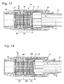
- Fig. 14 shows an embodiment of a clamping device 102 with a clamping ring assembly 103, the clamping ring packages 107, 108 and 109 includes.
- the spring constant of the clamping ring packages 107, 108, 109 takes on the pressure surface 29 in the direction the tail 19 from.
- the spring constant is constant.
- the clamping ring package 107 adjoins the pressure surface 29.
- the clamping ring package 107 comprises two groups of three mutually parallel clamping rings 14, wherein the two groups of clamping rings 14 are connected in series with each other.
- the subsequent clamping ring package 108 has a smaller spring constant than the clamping ring package 107.
- the clamping ring package 108 comprises two groups of two mutually parallel clamping rings 14, wherein the two groups of clamping rings 14 are connected in series.
- the spring rate of the clamping ring package 109 is smaller than the spring constant of the clamping ring package 108. This ensures that when fixing the clamping device 102, first the clamping rings 14 of the end piece 19 closest Spannringvers 109 on clamp the inner tube 10.
- the clamping rings 14 of the clamping ring package 108 are fixed on the inner tube 10 and only then the clamping rings 14 of the clamping ring package 107th
- the spring constant can be suitably adjusted in different areas of a clamping ring assembly. It may also be expedient to form clamping rings of a clamping ring arrangement with different inner diameters and / or different lengths of the clamping fingers in order to achieve a contact with the inner tube with different degrees of deformation of the clamping rings. A combination of different dimensions and suitable arrangement of the clamping rings may be advantageous in order to achieve a desired clamping behavior on the inner tube.
- the spring constant of a clamping ring package or the deformation of a clamping ring package which is necessary to clamp the clamping rings of the clamping ring package on the inner tube, the larger, the farther the clamping ring package from the stop, in particular from the end piece 19, is located. This allows a more uniform load on the clamping rings.
- the outermost and innermost clamping ring 14 contact the pressure surface 29 and the stop respectively with their concave, first axial side 65.
- the force is introduced into the outermost clamping ring 14 or discharge from the innermost clamping ring 14 at its large diameter.
- the clamping rings 14 with their convex, second axial side 66 to the pressure surface 29 and the stop show and the contact thus takes place at the small diameter.
- the stop is formed by the seal 15.
Priority Applications (1)
| Application Number | Priority Date | Filing Date | Title |
|---|---|---|---|
| EP16000362.0A EP3058808B1 (fr) | 2015-02-17 | 2016-02-13 | Appareil de travail portatif dote d'une section telescopique |
Applications Claiming Priority (2)
| Application Number | Priority Date | Filing Date | Title |
|---|---|---|---|
| EP15000469.5A EP3058807A1 (fr) | 2015-02-17 | 2015-02-17 | Appareil de travail manuel doté d'une section télescopique |
| EP16000362.0A EP3058808B1 (fr) | 2015-02-17 | 2016-02-13 | Appareil de travail portatif dote d'une section telescopique |
Publications (2)
| Publication Number | Publication Date |
|---|---|
| EP3058808A1 true EP3058808A1 (fr) | 2016-08-24 |
| EP3058808B1 EP3058808B1 (fr) | 2021-08-18 |
Family
ID=52544255
Family Applications (2)
| Application Number | Title | Priority Date | Filing Date |
|---|---|---|---|
| EP15000469.5A Withdrawn EP3058807A1 (fr) | 2015-02-17 | 2015-02-17 | Appareil de travail manuel doté d'une section télescopique |
| EP16000362.0A Active EP3058808B1 (fr) | 2015-02-17 | 2016-02-13 | Appareil de travail portatif dote d'une section telescopique |
Family Applications Before (1)
| Application Number | Title | Priority Date | Filing Date |
|---|---|---|---|
| EP15000469.5A Withdrawn EP3058807A1 (fr) | 2015-02-17 | 2015-02-17 | Appareil de travail manuel doté d'une section télescopique |
Country Status (3)
| Country | Link |
|---|---|
| US (1) | US10302142B2 (fr) |
| EP (2) | EP3058807A1 (fr) |
| CN (1) | CN105881462B (fr) |
Families Citing this family (10)
| Publication number | Priority date | Publication date | Assignee | Title |
|---|---|---|---|---|
| US11343973B2 (en) | 2018-05-23 | 2022-05-31 | Milwaukee Electric Tool Corporation | Pole saw |
| EP3599059B1 (fr) * | 2018-07-25 | 2022-05-04 | Andreas Stihl AG & Co. KG | Outil de travail à main et procédé de montage d'un élément anti-vibratoire d'un outil de travail à main |
| FR3084990A1 (fr) | 2018-08-17 | 2020-02-21 | Philippe CROCHAT | Dispositif d’elagage comportant au moins un manche de prehension, un outil de taille/debroussaillage et des moyens de levitation aerodynamique motorises |
| FR3085012B1 (fr) | 2018-08-17 | 2021-01-01 | Philippe Crochat | Ensemble comportant un manche de prehension pour un outil de travail et des moyens de levitation aerodynamique motorises |
| US11518018B2 (en) | 2019-01-21 | 2022-12-06 | Milwaukee Electric Tool Corporation | Power tool with non-conductive driveshaft |
| JP2022525175A (ja) * | 2019-03-13 | 2022-05-11 | シェルタード ウィングス インコーポレイテッド | 固定プラットフォーム用のコラム及び脚部ロック組立体 |
| US11384719B2 (en) | 2019-03-15 | 2022-07-12 | Milwaukee Electric Tool Corporation | Fluid tank for a power tool |
| US11618149B2 (en) | 2019-04-26 | 2023-04-04 | Milwaukee Electric Tool Corporation | Telescoping tool with collapsible bearing assembly |
| KR102385282B1 (ko) * | 2021-06-22 | 2022-04-08 | 강재성 | 공차 보정 시스템 |
| CN113944684B (zh) * | 2021-12-02 | 2022-08-09 | 柴琳 | 同轴动力传动可伸缩装置 |
Citations (4)
| Publication number | Priority date | Publication date | Assignee | Title |
|---|---|---|---|---|
| US3284114A (en) * | 1964-08-21 | 1966-11-08 | Vermont American Corp | Telescoping pole |
| US5011104A (en) * | 1990-05-07 | 1991-04-30 | Tatung Company Of America, Inc. | Adjustable frame |
| DE19618024A1 (de) | 1996-05-04 | 1997-11-06 | Stihl Maschf Andreas | Arbeitsgerät zum Entasten von Bäumen |
| US20020172548A1 (en) * | 2001-05-16 | 2002-11-21 | Jung-Hsien Chang | Locating device fo expandable rod |
Family Cites Families (7)
| Publication number | Priority date | Publication date | Assignee | Title |
|---|---|---|---|---|
| GB1384249A (en) * | 1971-06-25 | 1975-02-19 | Gkn Transmissions Ltd | Manufacture of diaphragm springs |
| US5013282A (en) * | 1989-11-20 | 1991-05-07 | Technic Tool Corporation | Extendible shaft assembly for portable tools |
| WO1996003065A1 (fr) * | 1994-07-27 | 1996-02-08 | Hoelle Erwin | Dispositif d'arret a systeme de freinage progressif |
| US7066511B2 (en) * | 2003-03-27 | 2006-06-27 | Specialty Products Of Greenwood, Missouri, Inc. | Non-conductive extension pole |
| US7344005B2 (en) * | 2003-11-18 | 2008-03-18 | General Motors Corporation | Self locking apparatus |
| ITPD20050381A1 (it) * | 2005-12-28 | 2007-06-29 | Lino Manfrotto & Co Spa | Supporto telescopico regolabile |
| CN201552561U (zh) * | 2009-12-11 | 2010-08-18 | 陈寅 | 电动工具的伸缩管 |
-
2015
- 2015-02-17 EP EP15000469.5A patent/EP3058807A1/fr not_active Withdrawn
-
2016
- 2016-02-10 US US15/040,459 patent/US10302142B2/en active Active
- 2016-02-13 EP EP16000362.0A patent/EP3058808B1/fr active Active
- 2016-02-17 CN CN201610088448.2A patent/CN105881462B/zh active Active
Patent Citations (4)
| Publication number | Priority date | Publication date | Assignee | Title |
|---|---|---|---|---|
| US3284114A (en) * | 1964-08-21 | 1966-11-08 | Vermont American Corp | Telescoping pole |
| US5011104A (en) * | 1990-05-07 | 1991-04-30 | Tatung Company Of America, Inc. | Adjustable frame |
| DE19618024A1 (de) | 1996-05-04 | 1997-11-06 | Stihl Maschf Andreas | Arbeitsgerät zum Entasten von Bäumen |
| US20020172548A1 (en) * | 2001-05-16 | 2002-11-21 | Jung-Hsien Chang | Locating device fo expandable rod |
Also Published As
| Publication number | Publication date |
|---|---|
| EP3058807A1 (fr) | 2016-08-24 |
| CN105881462B (zh) | 2020-11-10 |
| US10302142B2 (en) | 2019-05-28 |
| CN105881462A (zh) | 2016-08-24 |
| EP3058808B1 (fr) | 2021-08-18 |
| US20160238082A1 (en) | 2016-08-18 |
Similar Documents
| Publication | Publication Date | Title |
|---|---|---|
| EP3058808B1 (fr) | Appareil de travail portatif dote d'une section telescopique | |
| DE60206045T2 (de) | Kabelverschluss | |
| EP1846183B1 (fr) | Dispositif de préhension servant au montage de bagues d'élasticité du type du caoutchouc, et doigts utilises pour un tel dispositif | |
| DE102012102914B4 (de) | Spannvorrichtung für ein Werkstück oder Werkzeug | |
| EP1519813A2 (fr) | Appareil de pressage electrohydraulique et procede pour faire fonctionner un tel appareil | |
| WO2013050604A1 (fr) | Dispositif de prehension ou de serrage | |
| WO1996035885A1 (fr) | Systeme de fixation pour arbre | |
| EP2913561B1 (fr) | Système d'engrenage planétaire motorisé et procédé permettant de relier un moteur à un engrenage planétaire pour fabriquer un agencement moteur-engrenage planétaire | |
| DE102009054923A1 (de) | Handwerkzeugmaschine | |
| DE2821336C2 (de) | Wickelkopf | |
| DE1475035B2 (de) | Befestigungsvorrichtung | |
| DE3136406C2 (fr) | ||
| DE10161356B4 (de) | Schraubgerät | |
| DE1813556A1 (de) | Bolzensetzgeraet | |
| EP2594367A1 (fr) | Outil de vissage doté d'un dispositif de limitation du couple transmis | |
| DE1948573C3 (de) | AnlaBmotor für Brennkraftmaschinen | |
| DE102019218637A1 (de) | Spindelantrieb und Verfahren zur Montage eines Spindelantriebs | |
| DE2330552A1 (de) | Rohr- oder schlauchkupplung | |
| DE3411670A1 (de) | Gewindebohrwerkzeug-aufnahmefutter | |
| DE3802154C2 (fr) | ||
| DE4425961A1 (de) | Planetengetriebe und dessen Verwendung | |
| DE4002459C2 (de) | Motorgetriebenes, handgeführtes Arbeitsgerät mit einer durch Antivibrationselemente abgekoppelten Griffanordnung | |
| EP4169669A1 (fr) | Appareil de travail guidé à la main | |
| WO2016045773A1 (fr) | Appareil de travail | |
| DE3118326A1 (de) | "anlasserantrieb fuer verbrennungskraftmaschinen" |
Legal Events
| Date | Code | Title | Description |
|---|---|---|---|
| PUAI | Public reference made under article 153(3) epc to a published international application that has entered the european phase |
Free format text: ORIGINAL CODE: 0009012 |
|
| AK | Designated contracting states |
Kind code of ref document: A1 Designated state(s): AL AT BE BG CH CY CZ DE DK EE ES FI FR GB GR HR HU IE IS IT LI LT LU LV MC MK MT NL NO PL PT RO RS SE SI SK SM TR |
|
| AX | Request for extension of the european patent |
Extension state: BA ME |
|
| STAA | Information on the status of an ep patent application or granted ep patent |
Free format text: STATUS: REQUEST FOR EXAMINATION WAS MADE |
|
| 17P | Request for examination filed |
Effective date: 20170113 |
|
| RBV | Designated contracting states (corrected) |
Designated state(s): AL AT BE BG CH CY CZ DE DK EE ES FI FR GB GR HR HU IE IS IT LI LT LU LV MC MK MT NL NO PL PT RO RS SE SI SK SM TR |
|
| GRAP | Despatch of communication of intention to grant a patent |
Free format text: ORIGINAL CODE: EPIDOSNIGR1 |
|
| STAA | Information on the status of an ep patent application or granted ep patent |
Free format text: STATUS: GRANT OF PATENT IS INTENDED |
|
| RIC1 | Information provided on ipc code assigned before grant |
Ipc: A01G 3/08 20060101AFI20210212BHEP Ipc: B27B 17/00 20060101ALI20210212BHEP Ipc: F16B 7/14 20060101ALI20210212BHEP |
|
| INTG | Intention to grant announced |
Effective date: 20210324 |
|
| RIN1 | Information on inventor provided before grant (corrected) |
Inventor name: BARTH, BENJAMIN Inventor name: FOEHRENBACH, JAN Inventor name: DENSBORN, GERD |
|
| GRAS | Grant fee paid |
Free format text: ORIGINAL CODE: EPIDOSNIGR3 |
|
| GRAA | (expected) grant |
Free format text: ORIGINAL CODE: 0009210 |
|
| STAA | Information on the status of an ep patent application or granted ep patent |
Free format text: STATUS: THE PATENT HAS BEEN GRANTED |
|
| AK | Designated contracting states |
Kind code of ref document: B1 Designated state(s): AL AT BE BG CH CY CZ DE DK EE ES FI FR GB GR HR HU IE IS IT LI LT LU LV MC MK MT NL NO PL PT RO RS SE SI SK SM TR |
|
| REG | Reference to a national code |
Ref country code: GB Ref legal event code: FG4D Free format text: NOT ENGLISH |
|
| REG | Reference to a national code |
Ref country code: CH Ref legal event code: EP |
|
| REG | Reference to a national code |
Ref country code: DE Ref legal event code: R096 Ref document number: 502016013630 Country of ref document: DE |
|
| REG | Reference to a national code |
Ref country code: IE Ref legal event code: FG4D Free format text: LANGUAGE OF EP DOCUMENT: GERMAN Ref country code: AT Ref legal event code: REF Ref document number: 1420786 Country of ref document: AT Kind code of ref document: T Effective date: 20210915 |
|
| REG | Reference to a national code |
Ref country code: LT Ref legal event code: MG9D |
|
| REG | Reference to a national code |
Ref country code: NL Ref legal event code: MP Effective date: 20210818 |
|
| PG25 | Lapsed in a contracting state [announced via postgrant information from national office to epo] |
Ref country code: BG Free format text: LAPSE BECAUSE OF FAILURE TO SUBMIT A TRANSLATION OF THE DESCRIPTION OR TO PAY THE FEE WITHIN THE PRESCRIBED TIME-LIMIT Effective date: 20211118 Ref country code: LT Free format text: LAPSE BECAUSE OF FAILURE TO SUBMIT A TRANSLATION OF THE DESCRIPTION OR TO PAY THE FEE WITHIN THE PRESCRIBED TIME-LIMIT Effective date: 20210818 Ref country code: ES Free format text: LAPSE BECAUSE OF FAILURE TO SUBMIT A TRANSLATION OF THE DESCRIPTION OR TO PAY THE FEE WITHIN THE PRESCRIBED TIME-LIMIT Effective date: 20210818 Ref country code: FI Free format text: LAPSE BECAUSE OF FAILURE TO SUBMIT A TRANSLATION OF THE DESCRIPTION OR TO PAY THE FEE WITHIN THE PRESCRIBED TIME-LIMIT Effective date: 20210818 Ref country code: PT Free format text: LAPSE BECAUSE OF FAILURE TO SUBMIT A TRANSLATION OF THE DESCRIPTION OR TO PAY THE FEE WITHIN THE PRESCRIBED TIME-LIMIT Effective date: 20211220 Ref country code: NO Free format text: LAPSE BECAUSE OF FAILURE TO SUBMIT A TRANSLATION OF THE DESCRIPTION OR TO PAY THE FEE WITHIN THE PRESCRIBED TIME-LIMIT Effective date: 20211118 Ref country code: SE Free format text: LAPSE BECAUSE OF FAILURE TO SUBMIT A TRANSLATION OF THE DESCRIPTION OR TO PAY THE FEE WITHIN THE PRESCRIBED TIME-LIMIT Effective date: 20210818 Ref country code: RS Free format text: LAPSE BECAUSE OF FAILURE TO SUBMIT A TRANSLATION OF THE DESCRIPTION OR TO PAY THE FEE WITHIN THE PRESCRIBED TIME-LIMIT Effective date: 20210818 Ref country code: HR Free format text: LAPSE BECAUSE OF FAILURE TO SUBMIT A TRANSLATION OF THE DESCRIPTION OR TO PAY THE FEE WITHIN THE PRESCRIBED TIME-LIMIT Effective date: 20210818 |
|
| PG25 | Lapsed in a contracting state [announced via postgrant information from national office to epo] |
Ref country code: PL Free format text: LAPSE BECAUSE OF FAILURE TO SUBMIT A TRANSLATION OF THE DESCRIPTION OR TO PAY THE FEE WITHIN THE PRESCRIBED TIME-LIMIT Effective date: 20210818 Ref country code: LV Free format text: LAPSE BECAUSE OF FAILURE TO SUBMIT A TRANSLATION OF THE DESCRIPTION OR TO PAY THE FEE WITHIN THE PRESCRIBED TIME-LIMIT Effective date: 20210818 Ref country code: GR Free format text: LAPSE BECAUSE OF FAILURE TO SUBMIT A TRANSLATION OF THE DESCRIPTION OR TO PAY THE FEE WITHIN THE PRESCRIBED TIME-LIMIT Effective date: 20211119 |
|
| PG25 | Lapsed in a contracting state [announced via postgrant information from national office to epo] |
Ref country code: NL Free format text: LAPSE BECAUSE OF FAILURE TO SUBMIT A TRANSLATION OF THE DESCRIPTION OR TO PAY THE FEE WITHIN THE PRESCRIBED TIME-LIMIT Effective date: 20210818 |
|
| PG25 | Lapsed in a contracting state [announced via postgrant information from national office to epo] |
Ref country code: DK Free format text: LAPSE BECAUSE OF FAILURE TO SUBMIT A TRANSLATION OF THE DESCRIPTION OR TO PAY THE FEE WITHIN THE PRESCRIBED TIME-LIMIT Effective date: 20210818 |
|
| REG | Reference to a national code |
Ref country code: DE Ref legal event code: R097 Ref document number: 502016013630 Country of ref document: DE |
|
| PG25 | Lapsed in a contracting state [announced via postgrant information from national office to epo] |
Ref country code: SM Free format text: LAPSE BECAUSE OF FAILURE TO SUBMIT A TRANSLATION OF THE DESCRIPTION OR TO PAY THE FEE WITHIN THE PRESCRIBED TIME-LIMIT Effective date: 20210818 Ref country code: SK Free format text: LAPSE BECAUSE OF FAILURE TO SUBMIT A TRANSLATION OF THE DESCRIPTION OR TO PAY THE FEE WITHIN THE PRESCRIBED TIME-LIMIT Effective date: 20210818 Ref country code: RO Free format text: LAPSE BECAUSE OF FAILURE TO SUBMIT A TRANSLATION OF THE DESCRIPTION OR TO PAY THE FEE WITHIN THE PRESCRIBED TIME-LIMIT Effective date: 20210818 Ref country code: EE Free format text: LAPSE BECAUSE OF FAILURE TO SUBMIT A TRANSLATION OF THE DESCRIPTION OR TO PAY THE FEE WITHIN THE PRESCRIBED TIME-LIMIT Effective date: 20210818 Ref country code: CZ Free format text: LAPSE BECAUSE OF FAILURE TO SUBMIT A TRANSLATION OF THE DESCRIPTION OR TO PAY THE FEE WITHIN THE PRESCRIBED TIME-LIMIT Effective date: 20210818 Ref country code: AL Free format text: LAPSE BECAUSE OF FAILURE TO SUBMIT A TRANSLATION OF THE DESCRIPTION OR TO PAY THE FEE WITHIN THE PRESCRIBED TIME-LIMIT Effective date: 20210818 |
|
| PLBE | No opposition filed within time limit |
Free format text: ORIGINAL CODE: 0009261 |
|
| STAA | Information on the status of an ep patent application or granted ep patent |
Free format text: STATUS: NO OPPOSITION FILED WITHIN TIME LIMIT |
|
| 26N | No opposition filed |
Effective date: 20220519 |
|
| PG25 | Lapsed in a contracting state [announced via postgrant information from national office to epo] |
Ref country code: IT Free format text: LAPSE BECAUSE OF FAILURE TO SUBMIT A TRANSLATION OF THE DESCRIPTION OR TO PAY THE FEE WITHIN THE PRESCRIBED TIME-LIMIT Effective date: 20210818 |
|
| PG25 | Lapsed in a contracting state [announced via postgrant information from national office to epo] |
Ref country code: SI Free format text: LAPSE BECAUSE OF FAILURE TO SUBMIT A TRANSLATION OF THE DESCRIPTION OR TO PAY THE FEE WITHIN THE PRESCRIBED TIME-LIMIT Effective date: 20210818 |
|
| PG25 | Lapsed in a contracting state [announced via postgrant information from national office to epo] |
Ref country code: MC Free format text: LAPSE BECAUSE OF FAILURE TO SUBMIT A TRANSLATION OF THE DESCRIPTION OR TO PAY THE FEE WITHIN THE PRESCRIBED TIME-LIMIT Effective date: 20210818 |
|
| REG | Reference to a national code |
Ref country code: CH Ref legal event code: PL |
|
| REG | Reference to a national code |
Ref country code: BE Ref legal event code: MM Effective date: 20220228 |
|
| GBPC | Gb: european patent ceased through non-payment of renewal fee |
Effective date: 20220213 |
|
| PG25 | Lapsed in a contracting state [announced via postgrant information from national office to epo] |
Ref country code: LU Free format text: LAPSE BECAUSE OF NON-PAYMENT OF DUE FEES Effective date: 20220213 |
|
| PG25 | Lapsed in a contracting state [announced via postgrant information from national office to epo] |
Ref country code: LI Free format text: LAPSE BECAUSE OF NON-PAYMENT OF DUE FEES Effective date: 20220228 Ref country code: IE Free format text: LAPSE BECAUSE OF NON-PAYMENT OF DUE FEES Effective date: 20220213 Ref country code: GB Free format text: LAPSE BECAUSE OF NON-PAYMENT OF DUE FEES Effective date: 20220213 Ref country code: CH Free format text: LAPSE BECAUSE OF NON-PAYMENT OF DUE FEES Effective date: 20220228 |
|
| PG25 | Lapsed in a contracting state [announced via postgrant information from national office to epo] |
Ref country code: BE Free format text: LAPSE BECAUSE OF NON-PAYMENT OF DUE FEES Effective date: 20220228 |
|
| REG | Reference to a national code |
Ref country code: AT Ref legal event code: MM01 Ref document number: 1420786 Country of ref document: AT Kind code of ref document: T Effective date: 20220213 |
|
| PG25 | Lapsed in a contracting state [announced via postgrant information from national office to epo] |
Ref country code: AT Free format text: LAPSE BECAUSE OF NON-PAYMENT OF DUE FEES Effective date: 20220213 |
|
| PGFP | Annual fee paid to national office [announced via postgrant information from national office to epo] |
Ref country code: FR Payment date: 20230223 Year of fee payment: 8 |
|
| PGFP | Annual fee paid to national office [announced via postgrant information from national office to epo] |
Ref country code: DE Payment date: 20230227 Year of fee payment: 8 |
|
| PG25 | Lapsed in a contracting state [announced via postgrant information from national office to epo] |
Ref country code: HU Free format text: LAPSE BECAUSE OF FAILURE TO SUBMIT A TRANSLATION OF THE DESCRIPTION OR TO PAY THE FEE WITHIN THE PRESCRIBED TIME-LIMIT; INVALID AB INITIO Effective date: 20160213 |