EP3058808A1 - Hand-held work device with a telescopic section - Google Patents
Hand-held work device with a telescopic section Download PDFInfo
- Publication number
- EP3058808A1 EP3058808A1 EP16000362.0A EP16000362A EP3058808A1 EP 3058808 A1 EP3058808 A1 EP 3058808A1 EP 16000362 A EP16000362 A EP 16000362A EP 3058808 A1 EP3058808 A1 EP 3058808A1
- Authority
- EP
- European Patent Office
- Prior art keywords
- clamping
- clamping ring
- inner tube
- tube
- piece
- Prior art date
- Legal status (The legal status is an assumption and is not a legal conclusion. Google has not performed a legal analysis and makes no representation as to the accuracy of the status listed.)
- Granted
Links
- 230000006835 compression Effects 0.000 claims abstract description 4
- 238000007906 compression Methods 0.000 claims abstract description 4
- 239000007858 starting material Substances 0.000 description 4
- 230000007423 decrease Effects 0.000 description 3
- 230000035882 stress Effects 0.000 description 3
- 229930040373 Paraformaldehyde Natural products 0.000 description 2
- 230000003247 decreasing effect Effects 0.000 description 2
- 238000004519 manufacturing process Methods 0.000 description 2
- 229920006324 polyoxymethylene Polymers 0.000 description 2
- 238000003466 welding Methods 0.000 description 2
- 230000032683 aging Effects 0.000 description 1
- 238000002485 combustion reaction Methods 0.000 description 1
- 238000010276 construction Methods 0.000 description 1
- 238000011109 contamination Methods 0.000 description 1
- 230000008878 coupling Effects 0.000 description 1
- 238000010168 coupling process Methods 0.000 description 1
- 238000005859 coupling reaction Methods 0.000 description 1
- 238000006073 displacement reaction Methods 0.000 description 1
- 238000001746 injection moulding Methods 0.000 description 1
- 239000000463 material Substances 0.000 description 1
- 230000035515 penetration Effects 0.000 description 1
- -1 polyoxymethylene Polymers 0.000 description 1
- 230000008054 signal transmission Effects 0.000 description 1
Images


Classifications
-
- F—MECHANICAL ENGINEERING; LIGHTING; HEATING; WEAPONS; BLASTING
- F16—ENGINEERING ELEMENTS AND UNITS; GENERAL MEASURES FOR PRODUCING AND MAINTAINING EFFECTIVE FUNCTIONING OF MACHINES OR INSTALLATIONS; THERMAL INSULATION IN GENERAL
- F16D—COUPLINGS FOR TRANSMITTING ROTATION; CLUTCHES; BRAKES
- F16D3/00—Yielding couplings, i.e. with means permitting movement between the connected parts during the drive
- F16D3/02—Yielding couplings, i.e. with means permitting movement between the connected parts during the drive adapted to specific functions
- F16D3/06—Yielding couplings, i.e. with means permitting movement between the connected parts during the drive adapted to specific functions specially adapted to allow axial displacement
-
- B—PERFORMING OPERATIONS; TRANSPORTING
- B25—HAND TOOLS; PORTABLE POWER-DRIVEN TOOLS; MANIPULATORS
- B25F—COMBINATION OR MULTI-PURPOSE TOOLS NOT OTHERWISE PROVIDED FOR; DETAILS OR COMPONENTS OF PORTABLE POWER-DRIVEN TOOLS NOT PARTICULARLY RELATED TO THE OPERATIONS PERFORMED AND NOT OTHERWISE PROVIDED FOR
- B25F5/00—Details or components of portable power-driven tools not particularly related to the operations performed and not otherwise provided for
-
- B—PERFORMING OPERATIONS; TRANSPORTING
- B27—WORKING OR PRESERVING WOOD OR SIMILAR MATERIAL; NAILING OR STAPLING MACHINES IN GENERAL
- B27B—SAWS FOR WOOD OR SIMILAR MATERIAL; COMPONENTS OR ACCESSORIES THEREFOR
- B27B17/00—Chain saws; Equipment therefor
- B27B17/0008—Means for carrying the chain saw, e.g. handles
-
- A—HUMAN NECESSITIES
- A01—AGRICULTURE; FORESTRY; ANIMAL HUSBANDRY; HUNTING; TRAPPING; FISHING
- A01G—HORTICULTURE; CULTIVATION OF VEGETABLES, FLOWERS, RICE, FRUIT, VINES, HOPS OR SEAWEED; FORESTRY; WATERING
- A01G3/00—Cutting implements specially adapted for horticultural purposes; Delimbing standing trees
- A01G3/08—Other tools for pruning, branching or delimbing standing trees
- A01G3/085—Motor-driven saws for pruning or branching
- A01G3/086—Chain saws
-
- B—PERFORMING OPERATIONS; TRANSPORTING
- B25—HAND TOOLS; PORTABLE POWER-DRIVEN TOOLS; MANIPULATORS
- B25F—COMBINATION OR MULTI-PURPOSE TOOLS NOT OTHERWISE PROVIDED FOR; DETAILS OR COMPONENTS OF PORTABLE POWER-DRIVEN TOOLS NOT PARTICULARLY RELATED TO THE OPERATIONS PERFORMED AND NOT OTHERWISE PROVIDED FOR
- B25F5/00—Details or components of portable power-driven tools not particularly related to the operations performed and not otherwise provided for
- B25F5/001—Gearings, speed selectors, clutches or the like specially adapted for rotary tools
-
- F—MECHANICAL ENGINEERING; LIGHTING; HEATING; WEAPONS; BLASTING
- F16—ENGINEERING ELEMENTS AND UNITS; GENERAL MEASURES FOR PRODUCING AND MAINTAINING EFFECTIVE FUNCTIONING OF MACHINES OR INSTALLATIONS; THERMAL INSULATION IN GENERAL
- F16B—DEVICES FOR FASTENING OR SECURING CONSTRUCTIONAL ELEMENTS OR MACHINE PARTS TOGETHER, e.g. NAILS, BOLTS, CIRCLIPS, CLAMPS, CLIPS OR WEDGES; JOINTS OR JOINTING
- F16B7/00—Connections of rods or tubes, e.g. of non-circular section, mutually, including resilient connections
- F16B7/10—Telescoping systems
- F16B7/14—Telescoping systems locking in intermediate non-discrete positions
Definitions
- the invention relates to a hand-held implement with a telescopic section of the type specified in the preamble of claim 1.
- a pruner is known whose guide tube has a telescopic section.
- a clamping piece is provided which is tangentially tightened by means of screws and thereby fixed.
- the invention has for its object to provide a hand-held implement with a telescopic section of the generic type, which has a simple structure and allows for simplified operation.
- a clamping piece is provided, which is connected via a threaded connection with the outer tube and which is rotatably mounted relative to the inner tube.
- curved clamping ring is provided, which is supported on one axial side relative to the outer tube and on the other axial side relative to the clamping piece. If the clamping ring is compressed in the direction of a longitudinal central axis of the guide tube, then the opening of the clamping ring decreases.
- a rotation of the clamping piece causes due to the threaded connection an axial movement of the clamping piece relative to the outer tube. If the clamping piece is rotated so that the clamping ring is compressed in the direction of the longitudinal central axis of the guide tube, so the opening of the clamping ring decreases, whereby the clamping ring is clamped on the inner tube. As a result, the axial position of the clamping ring is fixed on the inner tube. Characterized in that the clamping ring is supported on one side opposite the outer tube and on the other axial side opposite the clamping piece, which in turn is connected to the outer tube via the threaded connection, the axial position of the outer tube relative to the inner tube is fixed. About the clamping piece, the clamping force is adjustable by appropriately wide turning of the clamping piece in a simple manner.
- the threaded connection can be a threaded connection that extends over several complete threads. However, the threads can also be interrupted.
- the threaded connection can also be designed in the manner of a bayonet connection whose thread extends over less than 360 °. It can also be provided a plurality of mutually parallel partial threads.
- the threaded connection can for example be provided so that a three-quarter turn is required for fixing and loosening.
- the threaded connection can advantageously have at least one latching position at an end position.
- a first detent position with dissolved clamping device and a second detent position are provided with a fixed clamping device.
- the clamping device can be easily solved and fixed by merely turning the clamping piece.
- the clamping device has no components such as screws or the like, which can be lost in the fully dissolved state of the clamping device.
- a tool is not needed for loosening and fixing the clamping device.
- About the at least one clamping ring can be a simple and secure fixation of the inner tube relative to the outer tube. Also a clamping unround Cross-sectional shapes is possible.
- the desired clamping force can be adjusted by appropriate design of the clamping ring and by adjusting the number of clamping rings. With decreasing clamping force, for example by aging, a simple replacement of at least one clamping ring is possible.
- an end piece is fixed to the outer tube, which carries an external thread of the threaded connection. Since the outer tube does not itself carry the external thread, a simple construction of the outer tube is possible.
- the threaded connection is advantageously designed as a fine thread with a low pitch. This results in a good adjustability of the clamping force.
- the pitch of the thread is advantageously less than 5 mm, in particular less than 3 mm. Due to the low pitch of the thread to be applied when turning the clamping piece torque is low, so that no tool is needed to rotate the clamping piece.
- the thread can advantageously be formed by individual threaded portions, which are spaced apart in the circumferential direction. As a result, the clamping piece and the end piece can be pushed one above the other in the axial direction, and the clamping device can be fixed by turning the clamping piece by significantly less than one revolution.
- the inner tube and the outer tube have a deviating from the circular cross-section.
- additional guide parts are provided to prevent rotation.
- the inner tube and the outer tube are designed in particular as welded tubes with a small wall thickness.
- the non-circular cross-section can be produced in a simple manner when straightening the welded tubes, in particular if the cross-section is a flattened circular cross-section, preferably a circular cross-section flattened on several sides.
- the cross section of the inner tube advantageously has flat sides, which are connected by rounded corners.
- the inner tube is held on at least one of its flat sides against rotation against the outer tube.
- the clamping piece is advantageously rotatably mounted relative to the inner tube. When fixing the clamping device, the clamping piece against the Inner tube and turned relative to the outer tube, while inner tube and outer tube are held against rotation to each other.
- the end piece is at least partially against the outer contour of the inner tube and positioned the inner tube and the outer tube against rotation to each other. Accordingly, the end piece advantageously serves both for the rotationally secure positioning of the inner tube and the outer tube relative to one another and also for producing the threaded connection to the clamping piece.
- the at least one clamping ring is supported on the outer tube via the end piece, so that a good introduction of force into the outer tube is simultaneously ensured via the end piece.
- the tail is only on the flat sides of the inner tube and not at the rounded corners.
- the flat sides of the inner tube can be easily manufactured with relatively high accuracy. Tolerance compensation is possible via the rounded corners, in particular if the inner tube is designed as a longitudinally welded tube whose flat sides are produced during straightening of the tube.
- the clamping piece has a pressure surface on which the at least one clamping ring is axially supported.
- the end piece advantageously has on its side facing away from the pressure surface means for centering the clamping piece.
- About the tail can be achieved in a simple manner, a good position assurance of the clamping piece.
- the clamping piece in an outer tube with a non-circular cross-section, can not or only partially supported on the outside of the outer tube, since the clamping piece must be rotatable relative to the inner tube.
- the clamping piece is not applied to the outer circumference of the inner tube.
- About the tail can be achieved in a simple way centering of the clamping piece.
- the clamping piece is designed in particular as a sleeve, which protrudes in the clamped state of the clamping device at least partially over the means for centering.
- the sleeve-shaped design of the clamping piece results in a compact appearance.
- One Stuck on outwardly projecting contours, as they are known in conventional clamping devices is thereby avoided.
- the means for centering preferably comprise an edge which at least partially closes an annular space between the outer tube and the clamping piece in the clamped state of the clamping device.
- the edge causes thereby at the same time a protection of the annulus from contamination.
- the tail does not form a stop for the clamping piece.
- the clamping piece can advantageously be pushed freely over the means for centering. As a result, even if the clamping force of the at least one clamping ring has decreased or if the use of a smaller number of clamping rings is provided, the clamping force can be fully tensioned.
- the at least one clamping ring advantageously has radially inwardly projecting clamping fingers, which press in the clamped state of the clamping device with its free end against the inner tube.
- the at least one clamping ring is advantageous in the untensioned state on the inner tube. As a result, a small clamping path is achieved.
- the clamping ring is advantageous in the longitudinal direction of the inner tube easily displaced to allow easy adjustability of the desired length of the telescopic section.
- the outer edge of the at least one clamping ring has a distance to the clamping piece in the radial direction. The clamping ring can thereby expand in axial compression and outward. In this case, a small radial gap between the clamping ring and the clamping piece is sufficient.
- a plurality of clamping rings are provided.
- the clamping rings advantageously form a clamping ring arrangement. At least two clamping rings are advantageously connected in series with each other.
- the clamping ring assembly may comprise one or more clamping ring packets, which are advantageously connected in series with each other.
- a clamping ring package consists of at least one clamping ring and can in particular more in series and / or comprise clamping rings connected in parallel with each other.
- a series circuit of clamping rings refers to the opposing arrangement of clamping rings and a parallel circuit a same direction arrangement of clamping rings.
- the spring constant is constant.
- Adjacent clamping rings are preferably in at least one clamping ring packet adjacent to their inner edges or adjacent to their outer edges to each other. In cross-section, this results in a zigzag-shaped course of the adjoining clamping rings.
- the clamping rings are arranged in a series connection.
- the clamping rings are not evenly loaded when operating the clamping device.
- the load on the adjacent to the pressure surface arranged clamping rings is higher than that of the clamping surface further away from the pressure surface arranged.
- the clamping ring assembly comprises a plurality of clamping ring packages with different spring constants.
- a first clamping ring packet is arranged with a first spring constant and, adjacent to the first clamping ring packet, a second clamping ring packet.
- the second clamping ring package has in particular a second, lower spring constant.
- the clamping rings advantageously have radially inwardly projecting clamping fingers.
- the at least one clamping ring is advantageously made of plastic.
- the plastic is in particular a POM (polyoxymethylene).
- a seal is provided which avoids the penetration of dirt between the inner tube and the outer tube.
- the seal is advantageously provided between the at least one clamping ring and the end piece.
- the seal between the clamping ring and a pressure surface of the clamping piece is provided.
- the inner cross section of the seal is advantageously adapted to the outer cross section of the inner tube.
- the inner tube and the outer tube advantageously each have a longitudinally extending weld.
- a guide part is arranged at the end of the inner tube protruding into the outer tube, which guides the inner tube in the outer tube.
- further guide parts are provided between inner tube and outer tube at a distance from the end of the inner tube.
- the drive motor is advantageously part of a drive unit which is arranged at a first end of the guide tube.
- the tool unit is advantageously arranged at a second end of the guide tube, wherein protrudes through the guide tube, a drive shaft which is formed as a telescopic shaft.
- the drive shaft serves to transmit the drive energy, as a rotation of the drive shaft about its longitudinal axis.
- the drive shaft is advantageously mounted on at least one bearing part in the inner tube.
- a plurality of axially spaced bearing parts are provided.
- the drive motor can also be arranged on the tool unit.
- the drive motor is then advantageously designed as an electric motor and via a cable, in particular a spiral cable, with a arranged at the other end of the guide tube power supply, in particular a battery connected.
- the cable is advantageously guided through the guide tube.
- Fig. 1 shows as an exemplary embodiment of a hand-held implement with a telescopic section a pruner 1. Instead of a pole pruner and another hand-held implement such as a hedge trimmer or the like may be provided.
- the pruner 1 has a drive unit 2 with a housing 40 in which a in Fig. 1 is schematically shown drive motor 41 is arranged.
- the pruner 1 also has a tool unit 3, which is connected via a guide tube 4 to the drive unit 2.
- the drive unit 2 is arranged at a first end 5 of the guide tube 4, and the tool unit 3 is held at a second end 6 of the guide tube 4.
- the tool unit 3 has a guide rail 7, on which a saw chain 8 is driven in rotation.
- the guide tube 4 has a telescopic section 9 which extends over a majority of the length of the guide tube 4.
- the guide tube has a longitudinal central axis 30.
- the telescopic section 9 has an inner tube 10, on which the tool unit 3 is fixed.
- the telescopic section 9 also comprises an outer tube 11, which is firmly connected to the drive unit 2.
- the inner tube 10 is fixed relative to the outer tube 11 via a releasable clamping device 12.
- the clamping device 12 has a clamping piece 13 which is rotatably mounted relative to the inner tube 10 and the outer tube 11. The design of the clamping device 12 will be explained in more detail below.
- Fig. 2 shows the structure of the drive unit 2 schematically.
- the drive motor 41 is arranged, which is designed as a single-cylinder internal combustion engine.
- the drive motor 41 is in particular a two-stroke engine or a mixture-lubricated four-stroke engine.
- the drive motor 41 has a cylinder 42 in which a piston 44 is reciprocally supported.
- the piston 44 drives via a connecting rod 45 a rotatably mounted in a crankcase 43 about a rotation axis 47 rotatably mounted crankshaft 46.
- the drive unit 2 has a starter device 48 for starting the drive motor 41.
- the starter device 48 is advantageously a pull starter to be started by hand. However, the starter 48 may also be an electrically operated pickup device.
- a fan 49 is fixed to the crankshaft 46. Between the fan 49 and the guide tube 4, a centrifugal clutch 50 is arranged, the output part is connected via a coupling part 51 with a drive shaft 23.
- the drive shaft 23 extends through the guide tube 4 and is also constructed telescopically, as will be explained in more detail below.
- Fig. 3 shows the structure of the clamping device 12 in detail.
- an end piece 19 is fixed.
- the other end of the outer tube 11 is fixed in the embodiment of the drive unit 2.
- the end piece 19 is non-rotatably and axially, ie in the direction of the longitudinal central axis 30, fixedly connected to the outer tube 11 via a locking connection 56 shown schematically.
- the end piece 19 forms a contact surface for a seal 15, which rests on the outer circumference of the inner tube 10 and the inner space between inner tube 10 and outer tube 11 seals.
- the inner cross section of the seal 15 is adapted to the outer cross section of the inner tube 10.
- the end piece 19 carries an external thread 20 of a threaded connection 16.
- the threaded connection 16 is formed as a fine thread with low pitch.
- the thread pitch is advantageously less than 5 mm, in particular less than 3 mm.
- a larger thread pitch in particular a thread pitch of about 5 mm to about 10 mm, but may be advantageous.
- the clamping piece 13 carries an internal thread 17 of the threaded connection 16.
- the clamping piece 13 is movable via the threaded connection 17 with respect to the outer tube 11.
- the clamping piece 13 has no contact.
- the clamping piece 13 is arranged rotatable relative to the inner tube 10 and axially displaceable.
- a plurality of clamping rings 14, which are arranged on the outer circumference of the inner tube 10 act. If the clamping rings 14 are compressed in the axial direction, that is to say in the direction of the longitudinal central axis 30 of the guide tube 4, then the opening of the clamping rings 14 is reduced, as a result of which the clamping rings 14 become clamped on the outer circumference of the inner tube 10.
- the clamping rings 14 are arranged in the axial direction between a pressure surface 29 of the clamping piece 13 and the end piece 19.
- the clamping rings 14 are each based with one axial side 65, 66 opposite the clamping piece 13 and with the other axial side 65, 66 relative to the end piece 19 from.
- the clamping rings 14 are connected in series in the manner of a series connection of springs.
- the force exerted on the clamping rings 14 acts between the outer tube 11 and the clamping piece 13 in the direction of the longitudinal central axis 30. If the clamping piece 13 is rotated so that the pressure surface 29 moves in the direction of the end piece 19, the clamping rings 14 in the direction of Longitudinal axis 30 compressed, thereby reducing the inner diameter.
- the clamping rings 14 thereby clamp on the inner tube 10.
- the clamping rings 14 are held simultaneously between the contact surface 29 and the end piece 19 and thereby fixed relative to the outer tube 11 in the axial direction. By squeezing the clamping rings 14, a fixation of the inner tube 10 relative to the outer tube 11 is achieved in a simple manner.
- the clamping piece 13 is sleeve-shaped.
- the pressure surface 29 is formed as an inwardly projecting edge on the side facing the tool unit 3 side of the clamping piece 13.
- clamping rings 14 are provided. However, it can also be provided a different number of clamping rings 14.
- the clamping piece 13 has on its outer tube 11 facing away from the tool unit 3 side recessed grips 18, which also in Fig. 1 are shown.
- the clamping piece 13 on its outer periphery also has a jacket 39, which advantageously consists of a soft plastic material.
- the clamping piece 13 is advantageously encapsulated with the jacket 39.
- the clamping piece 13 has a cylindrical outer periphery.
- another outer contour may also be advantageous, in particular to facilitate the gripping of the clamping piece 13.
- the outer diameter of the clamping piece 13 is comparatively large. As a result, the clamping piece 13 can be easily gripped by the operator, and it can also be applied to the clamping piece 13 even with tool-free operation, a comparatively large torque.
- annular space 34 is formed between the end piece 19 and the clamping piece 13 on the side facing away from the clamping rings 14 of the threaded connection 16.
- the end piece 19 has a radially outwardly projecting edge 21 which at least partially covers the annular space 34 in the axial direction.
- the edge 21 also serves to center the clamping piece 13 when the clamping piece 13 in Fig. 3 is screwed so far to the right that the clamping piece 13 engages over the edge 21.
- the end piece 19 also has a guide portion 22, with which the end piece 19 rests against the outer circumference of the inner tube 10. In the embodiment, the guide portion 22 forms a contact surface for the seal 15th Fig. 3 also shows the drive shaft 23.
- Fig. 4 shows the arrangement of the drive shaft 23 in the guide tube 4.
- the drive shaft 23 extends through the inner tube 10 and the outer tube 11.
- the drive shaft 23 has an inner shaft 24 which is mounted via a bearing element 26 in an outer shaft 25.
- the inner shaft 24 and the outer shaft 25 are rotatably connected to each other.
- the inner shaft 24 is telescopically inserted into the outer shaft 25.
- the bearing element 26 has outwardly projecting longitudinal ribs 27, with which the bearing element 26 is supported on the inner circumference of the outer shaft 25.
- Fig. 4 also shows the design of the inner tube 10 and the outer tube 11 in detail.
- the inner tube 10 has a non-round, flattened cross section, which is also in Fig. 5 is shown.
- the inner tube 10 has four flattened, planar sides 32, which are connected to each other via rounded corners 33. On one of the flat sides 32 extends a weld 37, which extends over the entire length of the inner tube 10. On the inside of the inner tube 10, the weld seam 37 forms an increase in the exemplary embodiment.
- the inner tube 10 is made as a welded tube from a flat surface blank. After welding the inner tube 10, the inner tube 10 is directed.
- the flat sides 32 are pressed by straightening rollers until the desired dimension of the inner tube 10, namely the desired distance between opposing planar sides 32, is reached.
- the end piece 19 is in the embodiment with its guide portion 22 (FIG. Fig. 3 ) only on the flat sides 32 of the inner tube 11 and not at the rounded corners 33rd
- the outer tube 11 has a non-round, flattened circular cross-section. Also, the outer tube 11 has a longitudinally extending weld 38.
- the outer tube 11 is also made as a welded tube and directed after welding under deformation. When straightening arise in the exemplary embodiment, four flat sides 62, which are connected to each other via rounded corners 63.
- the bearing part 52 bridges the distance between the outer shaft 25 and the inside of the inner tube 10 and thereby causes a centering of the outer shaft 25 in the inner tube 10.
- a plurality of bearing parts 52 are provided.
- Fig. 4 shows, the inner tube 10 and the outer tube 11 are telescoped with little radial play. Already due to the non-circular cross-sectional shape of inner tube 10 and outer tube 11, this results in a rotation.
- additional elements are provided which cause an anti-rotation between inner tube and outer tube.
- a guide part 61 is arranged on the projecting into the outer tube end of the inner tube 10, which guides the inner tube 10 in the outer tube 11.
- Fig. 7 shows a guide member 61 at the end of the inner tube 10 and another guide member 61 which is arranged at a distance from the end of the inner tube 10.
- the outer tube 11 On the outer circumference of the guide members 61, the outer tube 11 abuts when inner tube 10 and outer tube 11 are pushed far enough together, as Fig. 3 schematically shows.
- the clamping rings 14 have an inner edge 35 which rests on the outer circumference of the outer tube 10. The inner edge 35 rests against the flat sides 32 as well as at the rounded corners 33. As Fig. 5 also shows, the clamping rings 14 have an outer edge 36 which is radially spaced from the inside of the spanner 13. At the rounded corners of the clamping piece 13, only a narrow gap between clamping ring 14 and clamping piece 13 is formed. As the FIGS. 4 and 5 also show, the internal thread 17 of the clamping piece 13 is executed with three interruptions 57. As a result, a simple demolding in the manufacture of the clamping piece 13 in an injection molding process is possible.
- Fig. 6 shows the abutment of the end piece 19 on the inner tube 10.
- the guide portion 22 of the end piece 19 is formed by individual fingers 64 which are parallel to the longitudinal central axis 30th run and rest against the flat sides 32 of the inner tube 10.
- the end piece 19 is advantageously not on. Since the flat sides 32 are made with high accuracy, good, accurate guidance results.
- the rounded corners 33 can be used during manufacture for tolerance compensation.
- FIGS. 8 to 10 show the design of a clamping ring 14 in detail.
- the clamping ring 14 has a plurality of inwardly projecting clamping fingers 28.
- the end faces of the clamping fingers 28 form the inner edge 35 of the clamping ring 14.
- the individual clamping fingers 28 are separated by approximately radially extending slots 60.
- the inner edge 35 defines an opening 31 of the clamping ring 14, through which the inner tube 10 protrudes.
- three clamping fingers 28 for abutment on each flat side 32 and two clamping fingers 28 are provided for contact with each rounded corner 33 in the embodiment.
- the outer edge 36 is formed as a continuous edge, which also has flat sides, which are connected to each other via rounded corners. This results in an approximately equal length and elasticity of all clamping fingers 28.
- the clamping ring 14 has a central axis 58 which coincides in the installed state with the longitudinal central axis 30 of the guide tube 4.
- the clamping ring 14 has an approximately frusto-conical shape.
- the clamping ring 14 has an end face 59, which encloses an angle ⁇ with the central axis 58, which may be, for example, from about 40 ° to about 85 °. In the exemplary embodiment, an angle ⁇ is provided which is between 60 ° and 80 °.
- the clamping ring 14 has a first axial side 65, which adjoins the outer edge 36, and a second axial side 66, which adjoins the inner edge 35. If the clamping ring 14 is compressed in the axial direction by a clamping force F, then the clamping fingers 28 pivot inwards and reduce the size of the opening 31.
- Fig. 11 shows an embodiment of a Hochentasters 71.
- the Hochentaster 71 has instead of a drive unit 2, a housing 72 in which a battery 74 is arranged. Instead of the battery 74 may be provided on the housing 72 and a power cable for connection to a power supply.
- a tool unit 73 is arranged which comprises a guide rail 7 and a saw chain 8 arranged circumferentially on the guide rail 7. Identical reference characters indicate corresponding elements in all embodiments.
- the pole 67 has a cable 75 which connects the battery 74 in the housing 72 with a drive motor 81 of the tool unit 73.
- the cable 75 is advantageously designed as a spiral cable and has not only wires for power supply wires for signal transmission.
- the drive motor 81 is designed as an electric motor and supplied via the cable 75 with energy.
- the cable 75 is guided through the guide tube 4 and extends completely through the telescopic section 9, which in the embodiment according to Fig. 11 from the housing 72 to the tool unit 73 extends.
- the pressure force can not be forwarded to the adjacent clamping ring 14.
- Further tightening of the clamping device 12 can cause excessive deformation and stress on the already axially fixed clamping rings 14.
- the clamping rings 14 can move in the axial direction upon actuation of the clamping device 12 until all clamping rings 14 clamp with their openings 31 on the inner tube 10, the spring constant of the clamping rings 14 or clamping ring packages can be adjusted.
- Fig. 12 shows an embodiment of a clamping device 82, the clamping rings 14 form a clamping ring assembly 83.
- the clamping device 82 differs from the clamping device 12 substantially by the arrangement of the clamping rings 14.
- the clamping ring assembly 83 comprises a first clamping ring package 88, which abuts the pressure surface 29, a second clamping ring package 87 and a third clamping ring package 89th
- the third clamping ring package 89 is on the side facing away from the first clamping ring 88 side of the second clamping ring package 87 and is located on the seal 15 at.
- the second clamping ring package 87 is disposed between the first clamping ring package 88 and the third clamping ring package 89.
- the clamping ring arrangement 83 is symmetrical, so that the clamping ring arrangement 83 can be arranged with the first clamping ring package 88 or with the third clamping ring package 89 on the pressure surface 29.
- the first clamping ring package 88 comprises a plurality of, in the exemplary embodiment, two clamping rings 14 connected in parallel to one another.
- a plurality of clamping rings 14 are connected in series with one another.
- the third clamping ring package 89 several, in the embodiment, two clamping rings 14 are connected in parallel.
- a series circuit of clamping rings 14 denotes the opposing arrangement of successive clamping rings 14, and a parallel circuit denotes a co-directional arrangement of successive clamping rings 14.
- adjacent clamping rings 14 lie with their concave sides, ie their first axial sides 65 (FIGS. Fig. 10 ), or their convex sides, ie their second axial sides 66, to each other at.
- a concave side of a clamping ring 14 bears against the convex side of the adjacent clamping ring 14.
- Fig. 12 lie in the axial direction adjacent clamping rings 14 each to each other.
- the spring constant in the second clamping ring package 87 is smaller than the spring constant in the first clamping ring package 88 due to the series connection of the clamping rings.
- the spring constant in the second clamping ring packet 87 is also smaller than the spring constant in the third clamping ring packet 89.
- the spring constant increases starting from the pressure surface 29 first clamping ring package 88 to the second clamping ring package 87 and from the second clamping ring package 87 to the third clamping ring package 89 to.
- the spring constant in the first clamping ring package 88 and in the third clamping ring package 89 is the same size.
- Fig. 13 shows a further embodiment of a clamping device 92 with a clamping ring assembly 93.
- the clamping ring assembly 93 includes a clamping ring package 98, in which two clamping rings 14 are connected in parallel to each other and a clamping ring package 99, in which a plurality of clamping rings 14 are connected in series.
- the clamping ring package 98 has a higher spring constant than the clamping ring package 99 and is disposed adjacent to the pressure surface 29. As a result, the spring constant of the clamping ring package 93 decreases from the pressure surface 29 in the direction of the end piece 19. The clamping ring package 98 is thereby less compressed than the clamping ring package 99th
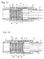
- Fig. 14 shows an embodiment of a clamping device 102 with a clamping ring assembly 103, the clamping ring packages 107, 108 and 109 includes.
- the spring constant of the clamping ring packages 107, 108, 109 takes on the pressure surface 29 in the direction the tail 19 from.
- the spring constant is constant.
- the clamping ring package 107 adjoins the pressure surface 29.
- the clamping ring package 107 comprises two groups of three mutually parallel clamping rings 14, wherein the two groups of clamping rings 14 are connected in series with each other.
- the subsequent clamping ring package 108 has a smaller spring constant than the clamping ring package 107.
- the clamping ring package 108 comprises two groups of two mutually parallel clamping rings 14, wherein the two groups of clamping rings 14 are connected in series.
- the spring rate of the clamping ring package 109 is smaller than the spring constant of the clamping ring package 108. This ensures that when fixing the clamping device 102, first the clamping rings 14 of the end piece 19 closest Spannringvers 109 on clamp the inner tube 10.
- the clamping rings 14 of the clamping ring package 108 are fixed on the inner tube 10 and only then the clamping rings 14 of the clamping ring package 107th
- the spring constant can be suitably adjusted in different areas of a clamping ring assembly. It may also be expedient to form clamping rings of a clamping ring arrangement with different inner diameters and / or different lengths of the clamping fingers in order to achieve a contact with the inner tube with different degrees of deformation of the clamping rings. A combination of different dimensions and suitable arrangement of the clamping rings may be advantageous in order to achieve a desired clamping behavior on the inner tube.
- the spring constant of a clamping ring package or the deformation of a clamping ring package which is necessary to clamp the clamping rings of the clamping ring package on the inner tube, the larger, the farther the clamping ring package from the stop, in particular from the end piece 19, is located. This allows a more uniform load on the clamping rings.
- the outermost and innermost clamping ring 14 contact the pressure surface 29 and the stop respectively with their concave, first axial side 65.
- the force is introduced into the outermost clamping ring 14 or discharge from the innermost clamping ring 14 at its large diameter.
- the clamping rings 14 with their convex, second axial side 66 to the pressure surface 29 and the stop show and the contact thus takes place at the small diameter.
- the stop is formed by the seal 15.
Landscapes
- Engineering & Computer Science (AREA)
- Life Sciences & Earth Sciences (AREA)
- Mechanical Engineering (AREA)
- General Engineering & Computer Science (AREA)
- Forests & Forestry (AREA)
- Wood Science & Technology (AREA)
- Biodiversity & Conservation Biology (AREA)
- Ecology (AREA)
- Environmental Sciences (AREA)
- Mutual Connection Of Rods And Tubes (AREA)
- Clamps And Clips (AREA)
- Endoscopes (AREA)
Abstract
Ein handgeführtes Arbeitsgerät besitzt einen Antriebsmotor (41) und eine Werkzeugeinheit (3), die ein von dem Antriebsmotor (41) angetriebenes Werkzeug umfasst. Das Arbeitsgerät besitzt ein Führungsrohr (4) mit einem Teleskopabschnitt (9), der ein Außenrohr (11) und ein darin längsverschiebbar geführtes Innenrohr (10) umfasst. Durch das Führungsrohr (4) sind Mittel zur Übertragung der Antriebsenergie für das Werkzeug geführt. Zur Fixierung des Innenrohrs (10) gegenüber dem Außenrohr (11) ist eine Klemmvorrichtung (12) vorgesehen. Die Klemmvorrichtung (12) umfasst ein Spannstück (13), das gegenüber dem Innenrohr (10) drehbar gelagert ist und über eine Gewindeverbindung mit dem Außenrohr (11) verbunden ist. Die Klemmvorrichtung (12) umfasst mindestens einen am Außenumfang des Innenrohrs (10) angeordneten, gewölbten Spannring (14). Ein Zusammendrücken des Spannrings in Richtung einer Längsmittelachse (39) des Führungsrohrs (4) bewirkt eine Verkleinerung einer Öffnung des Spannrings. Der mindestens eine Spannring (14) stützt sich dabei an der einen axialen Seite gegenüber dem Außenrohr und an der anderen axialen Seite gegenüber dem Spannstück (13) ab.A hand-held implement has a drive motor (41) and a tool unit (3) comprising a tool driven by the drive motor (41). The implement has a guide tube (4) with a telescopic section (9), which comprises an outer tube (11) and an inner tube (10) guided longitudinally displaceably therein. Through the guide tube (4) means for transmitting the drive power for the tool are performed. For fixing the inner tube (10) relative to the outer tube (11), a clamping device (12) is provided. The clamping device (12) comprises a clamping piece (13), which is rotatably mounted relative to the inner tube (10) and is connected via a threaded connection with the outer tube (11). The clamping device (12) comprises at least one, on the outer circumference of the inner tube (10) arranged, curved clamping ring (14). Compression of the clamping ring in the direction of a longitudinal central axis (39) of the guide tube (4) causes a reduction in an opening of the clamping ring. The at least one clamping ring (14) is supported on the one axial side relative to the outer tube and on the other axial side relative to the clamping piece (13).
Description
Die Erfindung betrifft ein handgeführtes Arbeitsgerät mit einem Teleskopabschnitt der im Oberbegriff des Anspruchs 1 angegebenen Gattung.The invention relates to a hand-held implement with a telescopic section of the type specified in the preamble of
Aus der
Der Erfindung liegt die Aufgabe zugrunde, ein handgeführtes Arbeitsgerät mit einem Teleskopabschnitt der gattungsgemäßen Art zu schaffen, das einen einfachen Aufbau besitzt und eine vereinfachte Bedienung ermöglicht.The invention has for its object to provide a hand-held implement with a telescopic section of the generic type, which has a simple structure and allows for simplified operation.
Diese Aufgabe wird durch ein handgeführtes Arbeitsgerät mit einem Teleskopabschnitt mit den Merkmalen des Anspruchs 1 gelöst.This object is achieved by a hand-held implement with a telescopic section with the features of
Für die Klemmvorrichtung, die das Innenrohr gegenüber dem Außenrohr des Teleskopabschnittes fixiert, ist ein Spannstück vorgesehen, das über eine Gewindeverbindung mit dem Außenrohr verbunden ist und das gegenüber dem Innenrohr drehbar gelagert ist. Es ist mindestens ein am Außenumfang des Innenrohrs angeordneter, gewölbter Spannring vorgesehen, der sich an einer axialen Seite gegenüber dem Außenrohr und an der anderen axialen Seite gegenüber dem Spannstück abstützt. Wird der Spannring in Richtung einer Längsmittelachse des Führungsrohrs zusammengedrückt, so verkleinert sich die Öffnung des Spannrings.For the clamping device which fixes the inner tube relative to the outer tube of the telescopic section, a clamping piece is provided, which is connected via a threaded connection with the outer tube and which is rotatably mounted relative to the inner tube. There is at least one arranged on the outer circumference of the inner tube, curved clamping ring is provided, which is supported on one axial side relative to the outer tube and on the other axial side relative to the clamping piece. If the clamping ring is compressed in the direction of a longitudinal central axis of the guide tube, then the opening of the clamping ring decreases.
Ein Drehen des Spannstücks bewirkt aufgrund der Gewindeverbindung eine axiale Bewegung des Spannstücks gegenüber dem Außenrohr. Wird das Spannstück so gedreht, dass der Spannring in Richtung der Längsmittelachse des Führungsrohrs zusammengedrückt wird, so verkleinert sich die Öffnung des Spannrings, wodurch der Spannring auf dem Innenrohr festgeklemmt wird. Dadurch ist die axiale Position des Spannrings auf dem Innenrohr festgelegt. Dadurch, dass sich der Spannring an einer Seite gegenüber dem Außenrohr und an der anderen axialen Seite gegenüber dem Spannstück abstützt, das seinerseits mit dem Außenrohr über die Gewindeverbindung verbunden ist, ist auch die axiale Position des Außenrohrs gegenüber dem Innenrohr festgelegt. Über das Spannstück ist die Spannkraft durch entsprechend weites Drehen des Spannstücks auf einfache Weise einstellbar.A rotation of the clamping piece causes due to the threaded connection an axial movement of the clamping piece relative to the outer tube. If the clamping piece is rotated so that the clamping ring is compressed in the direction of the longitudinal central axis of the guide tube, so the opening of the clamping ring decreases, whereby the clamping ring is clamped on the inner tube. As a result, the axial position of the clamping ring is fixed on the inner tube. Characterized in that the clamping ring is supported on one side opposite the outer tube and on the other axial side opposite the clamping piece, which in turn is connected to the outer tube via the threaded connection, the axial position of the outer tube relative to the inner tube is fixed. About the clamping piece, the clamping force is adjustable by appropriately wide turning of the clamping piece in a simple manner.
Die Gewindeverbindung kann dabei eine Gewindeverbindung sein, die sich über mehrere vollständige Gewindegänge erstreckt. Die Gewindegänge können jedoch auch unterbrochen sein. Die Gewindeverbindung kann auch nach Art einer Bajonettverbindung ausgebildet sein, deren Gewindegang sich über weniger als 360° erstreckt. Dabei können auch mehrere parallel zueinander verlaufende Teilgewindegänge vorgesehen sein. Die Gewindeverbindung kann beispielsweise so vorgesehen sein, dass zum Fixieren und Lösen eine drei Viertel Umdrehung benötigt wird. Die Gewindeverbindung kann vorteilhaft mindestens eine Raststellung an einer Endposition aufweisen. Vorteilhaft sind eine erste Raststellung bei gelöster Klemmvorrichtung und eine zweite Raststellung bei fixierter Klemmvorrichtung vorgesehen.The threaded connection can be a threaded connection that extends over several complete threads. However, the threads can also be interrupted. The threaded connection can also be designed in the manner of a bayonet connection whose thread extends over less than 360 °. It can also be provided a plurality of mutually parallel partial threads. The threaded connection can for example be provided so that a three-quarter turn is required for fixing and loosening. The threaded connection can advantageously have at least one latching position at an end position. Advantageously, a first detent position with dissolved clamping device and a second detent position are provided with a fixed clamping device.
Die Klemmvorrichtung kann einfach durch bloßes Drehen des Spannstücks gelöst und fixiert werden. Die Klemmvorrichtung besitzt keine Bauteile wie Schrauben oder dergleichen, die in vollständig gelöstem Zustand der Klemmvorrichtung verloren gehen können. Ein Werkzeug wird zum Lösen und Fixieren der Klemmvorrichtung nicht benötigt. Über den mindestens einen Spannring kann eine einfache und sichere Fixierung des Innenrohrs gegenüber dem Außenrohr erfolgen. Auch eine Klemmung unrunder Querschnittsformen ist möglich. Die gewünschte Klemmkraft kann durch entsprechende Auslegung des Spannrings und durch Anpassung der Anzahl der Spannringe eingestellt werden. Bei nachlassender Spannkraft, beispielsweise durch Alterung, ist ein einfacher Austausch des mindestens einen Spannrings möglich.The clamping device can be easily solved and fixed by merely turning the clamping piece. The clamping device has no components such as screws or the like, which can be lost in the fully dissolved state of the clamping device. A tool is not needed for loosening and fixing the clamping device. About the at least one clamping ring can be a simple and secure fixation of the inner tube relative to the outer tube. Also a clamping unround Cross-sectional shapes is possible. The desired clamping force can be adjusted by appropriate design of the clamping ring and by adjusting the number of clamping rings. With decreasing clamping force, for example by aging, a simple replacement of at least one clamping ring is possible.
Vorteilhaft ist am Außenrohr ein Endstück fixiert, das ein Außengewinde der Gewindeverbindung trägt. Da das Außenrohr nicht selbst das Außengewinde trägt, ist ein einfacher Aufbau des Außenrohrs möglich. Die Gewindeverbindung ist vorteilhaft als Feingewinde mit geringer Steigung ausgebildet. Dadurch ergibt sich eine gute Einstellbarkeit der Spannkraft. Die Steigung des Gewindes beträgt vorteilhaft weniger als 5 mm, insbesondere weniger als 3 mm. Aufgrund der geringen Gewindesteigung ist das beim Drehen des Spannstücks aufzubringende Drehmoment gering, so dass zum Drehen des Spannstücks kein Werkzeug benötigt wird. Das Gewinde kann vorteilhaft durch einzelne Gewindeabschnitte gebildet sein, die in Umfangsrichtung voneinander beabstandet sind. Dadurch können das Spannstück und das Endstück in axialer Richtung übereinander geschoben werden, und die Klemmvorrichtung kann durch Drehen des Spannstücks um deutlich weniger als eine Umdrehung fixiert werden.Advantageously, an end piece is fixed to the outer tube, which carries an external thread of the threaded connection. Since the outer tube does not itself carry the external thread, a simple construction of the outer tube is possible. The threaded connection is advantageously designed as a fine thread with a low pitch. This results in a good adjustability of the clamping force. The pitch of the thread is advantageously less than 5 mm, in particular less than 3 mm. Due to the low pitch of the thread to be applied when turning the clamping piece torque is low, so that no tool is needed to rotate the clamping piece. The thread can advantageously be formed by individual threaded portions, which are spaced apart in the circumferential direction. As a result, the clamping piece and the end piece can be pushed one above the other in the axial direction, and the clamping device can be fixed by turning the clamping piece by significantly less than one revolution.
Vorteilhaft weisen das Innenrohr und das Außenrohr einen von der Kreisform abweichenden Querschnitt auf. Dadurch ist über die Außenkontur von Innenrohr und Außenrohr eine Verdrehsicherung gegeben. Vorteilhaft sind zusätzliche Führungsteile zur Verdrehsicherung vorgesehen. Das Innenrohr und das Außenrohr sind insbesondere als geschweißte Rohre mit geringer Wandstärke ausgebildet. Der unrunde Querschnitt kann beim Richten der geschweißten Rohre auf einfache Weise hergestellt werden, insbesondere, wenn der Querschnitt ein abgeflachter Kreisquerschnitt, vorzugsweise ein an mehreren Seiten abgeflachter Kreisquerschnitt ist. Der Querschnitt des Innenrohrs weist vorteilhaft ebene Seiten auf, die über abgerundete Ecken verbunden sind. Vorteilhaft ist das Innenrohr an mindestens einer seiner ebenen Seiten verdrehsicher gegenüber dem Außenrohr gehalten. Das Spannstück ist vorteilhaft gegenüber dem Innenrohr drehbar gelagert. Beim Fixieren der Klemmvorrichtung wird das Spannstück gegenüber dem Innenrohr und gegenüber dem Außenrohr gedreht, während Innenrohr und Außenrohr verdrehsicher zueinander gehalten sind.Advantageously, the inner tube and the outer tube have a deviating from the circular cross-section. As a result, over the outer contour of inner tube and outer tube is given a rotation. Advantageously, additional guide parts are provided to prevent rotation. The inner tube and the outer tube are designed in particular as welded tubes with a small wall thickness. The non-circular cross-section can be produced in a simple manner when straightening the welded tubes, in particular if the cross-section is a flattened circular cross-section, preferably a circular cross-section flattened on several sides. The cross section of the inner tube advantageously has flat sides, which are connected by rounded corners. Advantageously, the inner tube is held on at least one of its flat sides against rotation against the outer tube. The clamping piece is advantageously rotatably mounted relative to the inner tube. When fixing the clamping device, the clamping piece against the Inner tube and turned relative to the outer tube, while inner tube and outer tube are held against rotation to each other.
Vorteilhaft liegt das Endstück mindestens teilweise an der Außenkontur des Innenrohrs an und positioniert das Innenrohr und das Außenrohr verdrehsicher zueinander. Das Endstück dient demnach vorteilhaft sowohl zur verdrehsicheren Positionierung von Innenrohr und Außenrohr zueinander als auch dazu, die Gewindeverbindung zum Spannstück herzustellen. Bevorzugt stützt sich der mindestens eine Spannring über das Endstück an dem Außenrohr ab, so dass über das Endstück gleichzeitig eine gute Krafteinleitung in das Außenrohr sichergestellt wird.Advantageously, the end piece is at least partially against the outer contour of the inner tube and positioned the inner tube and the outer tube against rotation to each other. Accordingly, the end piece advantageously serves both for the rotationally secure positioning of the inner tube and the outer tube relative to one another and also for producing the threaded connection to the clamping piece. Preferably, the at least one clamping ring is supported on the outer tube via the end piece, so that a good introduction of force into the outer tube is simultaneously ensured via the end piece.
Vorteilhaft liegt das Endstück nur an den ebenen Seiten des Innenrohrs und nicht an den abgerundeten Ecken an. Die ebenen Seiten des Innenrohrs können einfach mit vergleichsweise hoher Genauigkeit gefertigt werden. Über die abgerundeten Ecken ist ein Toleranzausgleich möglich, insbesondere, wenn das Innenrohr als längsgeschweißtes Rohr ausgebildet ist, dessen ebene Seiten beim Richten des Rohrs hergestellt werden.Advantageously, the tail is only on the flat sides of the inner tube and not at the rounded corners. The flat sides of the inner tube can be easily manufactured with relatively high accuracy. Tolerance compensation is possible via the rounded corners, in particular if the inner tube is designed as a longitudinally welded tube whose flat sides are produced during straightening of the tube.
Es ist vorteilhaft vorgesehen, dass das Spannstück eine Druckfläche aufweist, an der sich der mindestens eine Spannring axial abstützt. Das Endstück besitzt vorteilhaft an seiner der Druckfläche abgewandten Seite Mittel zur Zentrierung des Spannstücks. Über das Endstück kann so auf einfache Weise eine gute Lagesicherung des Spannstücks erreicht werden. Insbesondere bei einem Außenrohr mit unrundem Querschnitt kann sich das Spannstück nicht oder nur abschnittsweise an der Außenseite des Außenrohrs abstützen, da das Spannstück gegenüber dem Innenrohr drehbar sein muss. Bevorzugt liegt das Spannstück nicht am Außenumfang des Innenrohrs an. Über das Endstück kann auf einfache Weise eine Zentrierung des Spannstücks erreicht werden.It is advantageously provided that the clamping piece has a pressure surface on which the at least one clamping ring is axially supported. The end piece advantageously has on its side facing away from the pressure surface means for centering the clamping piece. About the tail can be achieved in a simple manner, a good position assurance of the clamping piece. In particular, in an outer tube with a non-circular cross-section, the clamping piece can not or only partially supported on the outside of the outer tube, since the clamping piece must be rotatable relative to the inner tube. Preferably, the clamping piece is not applied to the outer circumference of the inner tube. About the tail can be achieved in a simple way centering of the clamping piece.
Das Spannstück ist insbesondere als Hülse ausgebildet, die in verspanntem Zustand der Klemmvorrichtung mindestens teilweise über die Mittel zur Zentrierung ragt. Durch die hülsenförmige Ausbildung des Spannstücks ergibt sich ein kompaktes Äußeres. Ein Hängenbleiben an nach außen ragenden Konturen, wie sie bei herkömmlichen Klemmeinrichtungen bekannt sind, wird dadurch vermieden. Die Mittel zur Zentrierung umfassen bevorzugt einen Rand, der einen Ringraum zwischen dem Außenrohr und dem Spannstück in verspanntem Zustand der Klemmvorrichtung mindestens teilweise verschließt. Der Rand bewirkt dadurch zugleich einen Schutz des Ringraums vor Verschmutzung. Vorteilhaft bildet das Endstück keinen Anschlag für das Spannstück. Das Spannstück kann vorteilhaft frei über die Mittel zur Zentrierung geschoben werden. Dadurch kann die Klemmkraft auch dann, wenn die Spannkraft des mindestens einen Spannrings nachgelassen hat oder wenn der Einsatz einer geringeren Anzahl von Spannringen vorgesehen ist, vollständig gespannt werden.The clamping piece is designed in particular as a sleeve, which protrudes in the clamped state of the clamping device at least partially over the means for centering. The sleeve-shaped design of the clamping piece results in a compact appearance. One Stuck on outwardly projecting contours, as they are known in conventional clamping devices is thereby avoided. The means for centering preferably comprise an edge which at least partially closes an annular space between the outer tube and the clamping piece in the clamped state of the clamping device. The edge causes thereby at the same time a protection of the annulus from contamination. Advantageously, the tail does not form a stop for the clamping piece. The clamping piece can advantageously be pushed freely over the means for centering. As a result, even if the clamping force of the at least one clamping ring has decreased or if the use of a smaller number of clamping rings is provided, the clamping force can be fully tensioned.
Ein einfacher Aufbau ergibt sich, wenn das Endstück auf das Außenrohr aufgeclipst ist.A simple structure results when the tail is clipped onto the outer tube.
Der mindestens eine Spannring besitzt vorteilhaft radial nach innen ragende Klemmfinger, die in verspanntem Zustand der Klemmvorrichtung mit ihrem freien Ende gegen das Innenrohr drücken. Der mindestens eine Spannring liegt vorteilhaft in ungespanntem Zustand am Innenrohr an. Dadurch wird ein geringer Klemmweg erreicht. Der Spannring ist dabei vorteilhaft in Längsrichtung des Innenrohrs leicht verschiebbar, um eine einfache Einstellbarkeit der gewünschten Länge des Teleskopabschnitts zu erlauben. Um ein axiales Zusammendrücken des Spannrings zu ermöglichen, ist vorteilhaft vorgesehen, dass der Außenrand des mindestens einen Spannrings zum Spannstück einen Abstand in radialer Richtung besitzt. Der Spannring kann sich dadurch bei axialem Zusammendrücken auch nach außen aufweiten. Dabei ist ein geringer radialer Spalt zwischen dem Spannring und dem Spannstück ausreichend.The at least one clamping ring advantageously has radially inwardly projecting clamping fingers, which press in the clamped state of the clamping device with its free end against the inner tube. The at least one clamping ring is advantageous in the untensioned state on the inner tube. As a result, a small clamping path is achieved. The clamping ring is advantageous in the longitudinal direction of the inner tube easily displaced to allow easy adjustability of the desired length of the telescopic section. In order to enable an axial compression of the clamping ring, it is advantageously provided that the outer edge of the at least one clamping ring has a distance to the clamping piece in the radial direction. The clamping ring can thereby expand in axial compression and outward. In this case, a small radial gap between the clamping ring and the clamping piece is sufficient.
Vorteilhaft sind mehrere Spannringe vorgesehen. Die Spannringe bilden vorteilhaft eine Spannringanordnung. Mindestens zwei Spannringe sind dabei vorteilhaft in Reihe zueinander geschaltet. Die Spannringanordnung kann ein oder mehrere Spannringpakete umfassen, die vorteilhaft in Reihe zueinander geschaltet sind. Ein Spannringpaket besteht dabei aus mindestens einem Spannring und kann insbesondere mehrere in Reihe und/oder parallel zueinander geschaltete Spannringe umfassen. Eine Reihenschaltung von Spannringen bezeichnet dabei die gegensinnige Anordnung von Spannringen und eine Parallelschaltung eine gleichsinnige Anordnung von Spannringen. Innerhalb eines Spannringpakets ist die Federkonstante konstant.Advantageously, a plurality of clamping rings are provided. The clamping rings advantageously form a clamping ring arrangement. At least two clamping rings are advantageously connected in series with each other. The clamping ring assembly may comprise one or more clamping ring packets, which are advantageously connected in series with each other. A clamping ring package consists of at least one clamping ring and can in particular more in series and / or comprise clamping rings connected in parallel with each other. A series circuit of clamping rings refers to the opposing arrangement of clamping rings and a parallel circuit a same direction arrangement of clamping rings. Within a clamping ring package, the spring constant is constant.
Benachbarte Spannringe liegen bevorzugt in mindestens einem Spannringpaket jeweils benachbart zu ihren Innenrändern oder benachbart zu ihren Außenrändern aneinander an. Im Querschnitt ergibt sich dadurch ein zickzackförmiger Verlauf der aneinander anliegenden Spannringe. Die Spannringe sind in einer Reihenschaltung angeordnet.Adjacent clamping rings are preferably in at least one clamping ring packet adjacent to their inner edges or adjacent to their outer edges to each other. In cross-section, this results in a zigzag-shaped course of the adjoining clamping rings. The clamping rings are arranged in a series connection.
Es hat sich gezeigt, dass die Spannringe beim Betätigen der Klemmvorrichtung nicht gleichmäßig belastet werden. Die Belastung der benachbart zur Druckfläche angeordneten Spannringe ist höher als die der weiter von der Druckfläche entfernt angeordneten Spannringe. Zur Anpassung der Beanspruchung der Spannringe ist vorteilhaft vorgesehen, dass die Spannringanordnung mehrere Spannringpakete mit unterschiedlichen Federkonstanten umfasst. Bevorzugt ist angrenzend an mindestens eine Druckfläche ein erstes Spannringpaket mit einer ersten Federkonstante angeordnet und angrenzend an das erste Spannringpaket ein zweites Spannringpaket. Das zweite Spannringpaket besitzt insbesondere eine zweite, niedrigere Federkonstante. Um unterschiedliche Federkonstanten von Spannringpaketen zu erreichen, kann vorgesehen sein, den Innendurchmesser der Spannringe eines Spannringpakets geringer auszubilden als den Innendurchmesser der Spannringe eines anderen Spannringpakets. Die Spannringe besitzen vorteilhaft radial nach innen ragende Klemmfinger. Zur Anpassung der Federkonstante kann auch vorgesehen sein, dass die Länge der Klemmfinger unterschiedlicher Spannringe unterschiedlich ist. Auch eine Reihen- und/oder Parallelschaltung von Spannringen oder eine Kombination dieser Maßnahmen kann vorteilhaft sein. Der mindestens eine Spannring besteht vorteilhaft aus Kunststoff. Der Kunststoff ist insbesondere ein POM (Polyoxymethylen).It has been shown that the clamping rings are not evenly loaded when operating the clamping device. The load on the adjacent to the pressure surface arranged clamping rings is higher than that of the clamping surface further away from the pressure surface arranged. To adapt the stress of the clamping rings is advantageously provided that the clamping ring assembly comprises a plurality of clamping ring packages with different spring constants. Preferably, adjacent to at least one pressure surface, a first clamping ring packet is arranged with a first spring constant and, adjacent to the first clamping ring packet, a second clamping ring packet. The second clamping ring package has in particular a second, lower spring constant. In order to achieve different spring constants of clamping ring packages, it can be provided to make the inner diameter of the clamping rings of a clamping ring package smaller than the inner diameter of the clamping rings of another clamping ring package. The clamping rings advantageously have radially inwardly projecting clamping fingers. To adapt the spring constant can also be provided that the length of the clamping fingers of different clamping rings is different. Also, a series and / or parallel connection of clamping rings or a combination of these measures may be advantageous. The at least one clamping ring is advantageously made of plastic. The plastic is in particular a POM (polyoxymethylene).
Vorteilhaft ist eine Dichtung vorgesehen, die das Eindringen von Verschmutzungen zwischen das Innenrohr und das Außenrohr vermeidet. Die Dichtung ist vorteilhaft zwischen dem mindestens einen Spannring und dem Endstück vorgesehen. Es kann jedoch auch vorteilhaft sein, dass die Dichtung zwischen dem Spannring und einer Druckfläche des Spannstücks vorgesehen ist. Dadurch wird auch der Raum, in dem der mindestens eine Spannring angeordnet ist, gegenüber der Umgebung abgedichtet. Der Innenquerschnitt der Dichtung ist vorteilhaft auf den Außenquerschnitt des Innenrohrs angepasst. Das Innenrohr und das Außenrohr weisen vorteilhaft jeweils eine in Längsrichtung verlaufende Schweißnaht auf. Durch die Ausbildung als geschweißte Rohre können das Innenrohr und das Außenrohr gegenüber einem stranggepressten Rohr mit kreisförmigem Querschnitt mit verringerter Wandstärke ausgeführt werden. Dadurch ergibt sich ein verringertes Gewicht des Arbeitsgerätes.Advantageously, a seal is provided which avoids the penetration of dirt between the inner tube and the outer tube. The seal is advantageously provided between the at least one clamping ring and the end piece. However, it may also be advantageous that the seal between the clamping ring and a pressure surface of the clamping piece is provided. As a result, the space in which the at least one clamping ring is arranged, sealed against the environment. The inner cross section of the seal is advantageously adapted to the outer cross section of the inner tube. The inner tube and the outer tube advantageously each have a longitudinally extending weld. By being formed as welded tubes, the inner tube and the outer tube can be made opposite to an extruded tube of circular cross-section with reduced wall thickness. This results in a reduced weight of the implement.
Um eine gute Führung des Außenrohrs auf dem Innenrohr zu erreichen, ist vorteilhaft vorgesehen, dass an dem in das Außenrohr ragenden Ende des Innenrohrs ein Führungsteil angeordnet ist, das das Innenrohr im Außenrohr führt. Vorteilhaft sind weitere Führungsteile zwischen Innenrohr und Außenrohr in einem Abstand zum Ende des Innenrohrs vorgesehen.In order to achieve a good guidance of the outer tube on the inner tube, it is advantageously provided that a guide part is arranged at the end of the inner tube protruding into the outer tube, which guides the inner tube in the outer tube. Advantageously, further guide parts are provided between inner tube and outer tube at a distance from the end of the inner tube.
Der Antriebsmotor ist vorteilhaft Teil einer Antriebseinheit, die an einem ersten Ende des Führungsrohrs angeordnet ist. Die Werkzeugeinheit ist vorteilhaft an einem zweiten Ende des Führungsrohrs angeordnet, wobei durch das Führungsrohr eine Antriebswelle ragt, die als Teleskopwelle ausgebildet ist. Die Antriebswelle dient zur Übertragung der Antriebsenergie, und zwar als Rotation der Antriebswelle um ihre Längsachse. Die Antriebswelle ist vorteilhaft über mindestens ein Lagerteil in dem Innenrohr gelagert. Vorteilhaft sind mehrere, in axialem Abstand zueinander angeordnete Lagerteile vorgesehen. Der Antriebsmotor kann jedoch auch an der Werkzeugeinheit angeordnet sein. Der Antriebsmotor ist dann vorteilhaft als Elektromotor ausgebildet und über ein Kabel, insbesondere ein Spiralkabel, mit einer am anderen Ende des Führungsrohrs angeordneten Energieversorgung, insbesondere einem Akku, verbunden. Das Kabel ist dabei vorteilhaft durch das Führungsrohr geführt.The drive motor is advantageously part of a drive unit which is arranged at a first end of the guide tube. The tool unit is advantageously arranged at a second end of the guide tube, wherein protrudes through the guide tube, a drive shaft which is formed as a telescopic shaft. The drive shaft serves to transmit the drive energy, as a rotation of the drive shaft about its longitudinal axis. The drive shaft is advantageously mounted on at least one bearing part in the inner tube. Advantageously, a plurality of axially spaced bearing parts are provided. However, the drive motor can also be arranged on the tool unit. The drive motor is then advantageously designed as an electric motor and via a cable, in particular a spiral cable, with a arranged at the other end of the guide tube power supply, in particular a battery connected. The cable is advantageously guided through the guide tube.
Ausführungsbeispiele der Erfindung werden im Folgenden anhand der Zeichnung erläutert. Es zeigen:
- Fig. 1
- eine perspektivische Darstellung eines Hochentasters,
- Fig. 2
- eine schematische Darstellung der Antriebseinheit des Hochentasters aus
Fig. 1 , - Fig. 3
- einen Schnitt durch eine Klemmvorrichtung des Hochentasters aus
Fig. 1 , - Fig. 4
- einen Schnitt entlang der Linie IV-IV in
Fig. 3 , - Fig. 5
- einen Schnitt entlang der Linie V-V in
Fig. 3 , - Fig. 6
- einen Schnitt entlang der Linie VI-VI in
Fig. 3 , - Fig. 7
- eine perspektivische Darstellung eines Endabschnitts des Innenrohrs,
- Fig. 8
- eine perspektivische Darstellung eines Spannrings,
- Fig. 9
- eine Draufsicht auf den Spannring aus
Fig. 8 , - Fig. 10
- eine Seitenansicht in Richtung des Pfeils X in
Fig. 9 , - Fig. 11
- eine schematische Darstellung eines Ausführungsbeispiels eines Hochentasters,
- Fig. 12
bis 14 - Schnittdarstellungen von Ausführungsbeispielen von Klemmvorrichtungen.
- Fig. 1
- a perspective view of a pruner,
- Fig. 2
- a schematic representation of the drive unit of the Hochentasters
Fig. 1 . - Fig. 3
- a section through a clamping device of the Hochentasters
Fig. 1 . - Fig. 4
- a section along the line IV-IV in
Fig. 3 . - Fig. 5
- a section along the line VV in
Fig. 3 . - Fig. 6
- a section along the line VI-VI in
Fig. 3 . - Fig. 7
- a perspective view of an end portion of the inner tube,
- Fig. 8
- a perspective view of a clamping ring,
- Fig. 9
- a plan view of the clamping ring
Fig. 8 . - Fig. 10
- a side view in the direction of arrow X in
Fig. 9 . - Fig. 11
- a schematic representation of an embodiment of a pruner,
- Fig. 12 to 14
- Sectional views of embodiments of clamping devices.
Der Hochentaster 1 besitzt außerdem eine Werkzeugeinheit 3, die über ein Führungsrohr 4 mit der Antriebseinheit 2 verbunden ist. Die Antriebseinheit 2 ist dabei an einem ersten Ende 5 des Führungsrohrs 4 angeordnet, und die Werkzeugeinheit 3 ist an einem zweiten Ende 6 des Führungsrohrs 4 gehalten. Die Werkzeugeinheit 3 besitzt eine Führungsschiene 7, an der eine Sägekette 8 umlaufend angetrieben ist.The
Das Führungsrohr 4 besitzt einen Teleskopabschnitt 9, der sich über einen Großteil der Länge des Führungsrohrs 4 erstreckt. Das Führungsrohr besitzt eine Längsmittelachse 30. Benachbart zum ersten Ende 5 des Führungsrohrs 4 ist am Führungsrohr 4 ein Handgriff 53 angeordnet. Am Handgriff 53 sind Bedienelemente angeordnet, nämlich ein Gashebel 54 zur Bedienung des Antriebsmotors 41 sowie eine Gashebelsperre 55.The guide tube 4 has a
Der Teleskopabschnitt 9 besitzt ein Innenrohr 10, an dem die Werkzeugeinheit 3 festgelegt ist. Der Teleskopabschnitt 9 umfasst außerdem ein Außenrohr 11, das mit der Antriebseinheit 2 fest verbunden ist. Das Innenrohr 10 ist gegenüber dem Außenrohr 11 über eine lösbare Klemmvorrichtung 12 fixiert. Die Klemmvorrichtung 12 besitzt ein Spannstück 13, das gegenüber dem Innenrohr 10 und dem Außenrohr 11 drehbar gelagert ist. Die Gestaltung der Klemmvorrichtung 12 wird im Folgenden noch näher erläutert.The
Das Endstück 19 trägt ein Außengewinde 20 einer Gewindeverbindung 16. Über die Gewindeverbindung 16 sind das Spannstück 13 und das Endstück 19 miteinander verbunden. Wie
Wie
Im Ausführungsbeispiel sind acht Spannringe 14 vorgesehen. Es kann jedoch auch eine andere Anzahl von Spannringen 14 vorgesehen sein.In the embodiment, eight clamping rings 14 are provided. However, it can also be provided a different number of clamping rings 14.
Damit ein Drehen des Spannstücks 13 für den Bediener leicht möglich ist, besitzt das Spannstück 13 an seiner dem Außenrohr 11 abgewandten, der Werkzeugeinheit 3 zugewandten Seite Griffmulden 18, die auch in
Wie
Wie
Wie
Wie
Wie
Die
Wie die
Es hat sich gezeigt, dass die Beanspruchung der Spannringe 14 beim Betätigen der Klemmvorrichtung 12 nicht einheitlich ist. Die in der Nähe der Druckfläche 29 angeordneten Spannringe 14 erfahren eine hohe Belastung, während Spannringe 14 aus dem mittleren Bereich zwischen Druckfläche 29 und Dichtung 15 weniger stark belastet sind. Beim Betätigen der Klemmvorrichtung 12 wird an der Druckfläche 29 eine Druckkraft in Richtung der Längsmittelachse 30 in den benachbart zur Druckfläche 29 angeordneten Spannring 14 eingeleitet. Diese Druckkraft wird jeweils auf den angrenzenden Spannring 14 übertragen, solange die Spannringe 14 sich axial bewegen und zusammenrutschen können. Bewirkt die eingeleitete Druckkraft bereits eine zu starke Verformung eines Spannrings 14, so klemmt dieser auf dem Innenrohr 10, und eine weitere axiale Bewegung dieses Spannrings 14 ist verhindert. Dadurch kann die Druckkraft nicht mehr auf den benachbarten Spannring 14 weitergeleitet werden. Ein weiteres Anziehen der Klemmvorrichtung 12 kann eine übermäßige Verformung und Belastung der bereits axial fixierten Spannringe 14 bewirken. Um zu ermöglichen, dass die Spannringe 14 sich bei Betätigung der Klemmeinrichtung 12 in axialer Richtung bewegen können, bis alle Spannringe 14 mit ihren Öffnungen 31 auf dem Innenrohr 10 klemmen, können die Federkonstante der Spannringe 14 oder Spannringpakete angepasst werden.It has been found that the stress on the clamping rings 14 when operating the
Das erste Spannringpaket 88 umfasst mehrere, im Ausführungsbeispiel zwei parallel zueinander geschaltete Spannringe 14. Im zweiten Spannringpaket 87 sind mehrere Spannringe 14 in Reihe zueinander geschaltet. Im dritten Spannringpaket 89 sind mehrere, im Ausführungsbeispiel zwei Spannringe 14 parallel zueinander geschaltet.The first
Eine Reihenschaltung von Spannringen 14 bezeichnet die gegensinnige Anordnung aufeinanderfolgender Spannringe 14, und eine Parallelschaltung bezeichnet eine gleichsinnige Anordnung aufeinanderfolgender Spannringe 14. Bei der Reihenschaltung liegen benachbarte Spannringe 14 mit ihren konkaven Seiten, also ihren ersten axialen Seiten 65 (
Beim Ausführungsbeispiel nach
Durch geeignete Ausrichtung und Anordnung baugleicher Spannringe lässt sich die Federkonstante in unterschiedlichen Bereichen einer Spannringanordnung geeignet einstellen. Es kann auch zweckmäßig sein, Spannringe einer Spannringanordnung mit unterschiedlichen Innendurchmessern und/oder unterschiedlichen Längen der Klemmfinger auszubilden, um eine Anlage an dem Innenrohr bei unterschiedlich starker Verformung der Spannringe zu erreichen. Auch eine Kombination aus unterschiedlichen Abmessungen und geeigneter Anordnung der Spannringe kann vorteilhaft sein, um ein gewünschtes Klemmverhalten auf dem Innenrohr zu erreichen.By suitable alignment and arrangement of identical clamping rings, the spring constant can be suitably adjusted in different areas of a clamping ring assembly. It may also be expedient to form clamping rings of a clamping ring arrangement with different inner diameters and / or different lengths of the clamping fingers in order to achieve a contact with the inner tube with different degrees of deformation of the clamping rings. A combination of different dimensions and suitable arrangement of the clamping rings may be advantageous in order to achieve a desired clamping behavior on the inner tube.
Vorteilhaft ist die Federkonstante eines Spannringpakets oder die Verformung eines Spannringpakets, die notwendig ist, um die Spannringe des Spannringpakets auf dem Innenrohr festzuklemmen, umso größer, je weiter das Spannringpaket vom Anschlag, insbesondere vom Endstück 19, entfernt liegt. Dadurch wird eine gleichmäßigere Belastung der Spannringe ermöglicht.Advantageously, the spring constant of a clamping ring package or the deformation of a clamping ring package, which is necessary to clamp the clamping rings of the clamping ring package on the inner tube, the larger, the farther the clamping ring package from the stop, in particular from the
In den Ausführungsbeispielen kontaktieren der äußerste und innerste Spannring 14 die Druckfläche 29 bzw. den Anschlag jeweils mit ihrer konkaven, ersten axialen Seite 65. Die Krafteinleitung in den äußersten Spannring 14 bzw. Ausleitung aus dem innersten Spannring 14 erfolgt an ihrem großen Durchmesser. Es kann aber auch vorteilhaft sein, dass die Spannringe 14 mit ihrer konvexen, zweiten axialen Seite 66 zur Druckfläche 29 bzw. dem Anschlag zeigen und der Kontakt damit am kleinen Durchmesser erfolgt. In den Ausführungsbeispielen wird der Anschlag durch die Dichtung 15 gebildet.In the embodiments, the outermost and
Gleiche Bezugszeichen bezeichnen dabei in allen Figuren einander entsprechende Elemente. Zu den
Claims (17)
dadurch gekennzeichnet, dass die Klemmvorrichtung (12) ein Spannstück (13) umfasst, das gegenüber dem Innenrohr (10) drehbar gelagert ist und über eine Gewindeverbindung (16) mit dem Außenrohr (11) verbunden ist, dass die Klemmvorrichtung (12) mindestens einen am Außenumfang des Innenrohrs (10) angeordneten, gewölbten Spannring (14) umfasst, wobei ein Zusammendrücken des Spannrings (14) in Richtung einer Längsmittelachse des Führungsrohrs (4) eine Verkleinerung der Öffnung (31) des Spannrings (14) bewirkt, und dass der mindestens eine Spannring (14) sich an der einen axialen Seite (65, 66) gegenüber dem Außenrohr (11) und an der anderen axialen Seite (65, 66) gegenüber dem Spannstück (13) abstützt.Hand-guided implement with a drive motor (41, 81) and with a tool unit (3, 73), wherein the tool unit (3, 73) comprises a driven by the drive motor (41, 81) tool, wherein the implement a guide tube (4) a telescopic section (9), wherein the telescopic section (9) comprises an outer tube (11) and a longitudinally displaceably guided inner tube (10), wherein by the guide tube (4) means for transmitting the drive energy for the tool are guided, and wherein a Clamping device (12) for fixing the inner tube (10) relative to the outer tube (11) is provided,
characterized in that the clamping device (12) comprises a clamping piece (13) which is rotatably mounted relative to the inner tube (10) and is connected via a threaded connection (16) with the outer tube (11), that the clamping device (12) at least one on the outer circumference of the inner tube (10) arranged, curved clamping ring (14), wherein compression of the clamping ring (14) in the direction of a longitudinal central axis of the guide tube (4) causes a reduction of the opening (31) of the clamping ring (14), and in that at least one clamping ring (14) on one axial side (65, 66) relative to the outer tube (11) and on the other axial side (65, 66) relative to the clamping piece (13) is supported.
dadurch gekennzeichnet, dass am Außenrohr (11) ein Endstück (19) fixiert ist, das ein Außengewinde (20) der Gewindeverbindung (16) trägt.Working device according to claim 1,
characterized in that on the outer tube (11) an end piece (19) is fixed, which carries an external thread (20) of the threaded connection (16).
dadurch gekennzeichnet, dass das Innenrohr (10) und das Außenrohr (11) einen von der Kreisform abweichenden Querschnitt aufweisen.Working device according to claim 2,
characterized in that the inner tube (10) and the outer tube (11) have a deviating from the circular cross-section.
dadurch gekennzeichnet, dass der Querschnitt des Innenrohrs (10) ebene Seiten (32) besitzt, die über abgerundete Ecken (33) verbunden sind.Working device according to claim 3,
characterized in that the cross section of the inner tube (10) has planar sides (32) connected by rounded corners (33).
dadurch gekennzeichnet, dass das Innenrohr (10) an mindestens einer seiner ebenen Seiten (32) verdrehsicher gegenüber dem Außenrohr (11) gehalten ist.Working device according to claim 4,
characterized in that the inner tube (10) on at least one of its flat sides (32) is held against rotation with respect to the outer tube (11).
dadurch gekennzeichnet, dass das Endstück (19) mindestens teilweise an der Außenkontur des Innenrohrs (10) anliegt und das Innenrohr (10) und das Außenrohr (11) verdrehsicher zueinander positioniert.Tool according to claim 4 or 5,
characterized in that the end piece (19) at least partially against the outer contour of the inner tube (10) and the inner tube (10) and the outer tube (11) positioned against rotation to each other.
dadurch gekennzeichnet, dass das Endstück (19) nur an den ebenen Seiten (32) des Innenrohrs (10) und nicht an den abgerundeten Ecken (33) anliegt.Working device according to claim 6,
characterized in that the end piece (19) rests only on the flat sides (32) of the inner tube (10) and not on the rounded corners (33).
dadurch gekennzeichnet, dass das Spannstück (13) eine Druckfläche (29) aufweist, an der sich der mindestens eine Spannring (14) axial abstützt, und dass das Endstück (19) an seiner der Druckfläche (29) abgewandten Seite Mittel zur Zentrierung des Spannstücks (13) besitzt.Tool according to one of claims 2 to 7,
characterized in that the clamping piece (13) has a pressure surface (29) on which the at least one clamping ring (14) is axially supported, and that the end piece (19) on its side facing away from the pressure surface (29) means for centering the clamping piece (13).
dadurch gekennzeichnet, dass der mindestens eine Spannring (14) radial nach innen ragende Klemmfinger (28) aufweist, die in verspanntem Zustand mit ihrem freien Ende gegen das Innenrohr (10) drücken.Tool according to one of claims 1 to 8,
characterized in that the at least one clamping ring (14) radially inwardly projecting clamping fingers (28) which press in the clamped state with its free end against the inner tube (10).
dadurch gekennzeichnet, dass der mindestens eine Spannring (14) in ungespanntem Zustand am Innenrohr (10) anliegt, und dass der Außenrand (36) des mindestens einen Spannrings (14) zum Spannstück (13) einen radialen Abstand besitzt.Tool according to one of claims 1 to 9,
characterized in that the at least one clamping ring (14) in untensioned state on the inner tube (10) is present, and that the outer edge (36) of the at least one clamping ring (14) to the clamping piece (13) has a radial distance.
dadurch gekennzeichnet, dass mehrere Spannringe (14) vorgesehen sind.Tool according to one of claims 1 to 10,
characterized in that a plurality of clamping rings (14) are provided.
dadurch gekennzeichnet, dass die Spannringe (14) eine Spannringanordnung (83, 93, 103) bilden, in der mindestens zwei Spannringe (14) in Reihenschaltung zueinander angeordnet sind.Tool according to claim 11,
characterized in that the clamping rings (14) form a clamping ring arrangement (83, 93, 103) in which at least two clamping rings (14) are arranged in series connection to one another.
dadurch gekennzeichnet, dass die Spannringanordnung (83, 93, 103) mindestens zwei in Reihe zueinander geschaltete Spannringpakete (87, 88, 89, 98, 99, 107, 108, 109) umfasst, wobei die Federkonstante der Spannringpakete (87, 88, 89, 98, 99, 107, 108, 109) unterschiedlich ist.Tool according to claim 11,
characterized in that the clamping ring arrangement (83, 93, 103) comprises at least two clamping ring packets (87, 88, 89, 98, 99, 107, 108, 109) connected in series, the spring constant of the clamping ring packets (87, 88, 89 , 98, 99, 107, 108, 109) is different.
dadurch gekennzeichnet, dass angrenzend an mindestens eine Druckfläche (29) ein erstes Spannringpaket (88, 98, 107) mit einer ersten Federkonstante angeordnet ist und angrenzend an das erste Spannringpaket (88, 98, 107) ein zweites Spannringpaket (87, 99, 108) mit einer zweiten Federkonstante, wobei die zweite Federkonstante niedriger als die erste Federkonstante ist.Working device according to claim 13,
characterized in that adjacent to at least one pressure surface (29) a first clamping ring package (88, 98, 107) is arranged with a first spring constant and adjacent to the first clamping ring package (88, 98, 107) a second Clamping ring package (87, 99, 108) with a second spring constant, wherein the second spring constant is lower than the first spring constant.
dadurch gekennzeichnet, dass der mindestens eine Spannring (14) aus Kunststoff ist.Tool according to one of claims 1 to 14,
characterized in that the at least one clamping ring (14) is made of plastic.
dadurch gekennzeichnet, dass der Antriebsmotor Teil einer Antriebseinheit (2) ist, die an einem ersten Ende (5) des Führungsrohrs (4) angeordnet ist, dass die Werkzeugeinheit (3) an einem zweiten Ende (6) des Führungsrohrs (4) angeordnet ist, und dass durch das Führungsrohr (4) eine Antriebswelle (23) ragt, die als Teleskopwelle ausgebildet ist.Tool according to one of claims 1 to 15,
characterized in that the drive motor is part of a drive unit (2) disposed at a first end (5) of the guide tube (4), that the tool unit (3) at a second end (6) of the guide tube (4) is arranged , and that through the guide tube (4) a drive shaft (23) protrudes, which is formed as a telescopic shaft.
dadurch gekennzeichnet, dass die Antriebswelle (23) über mindestens ein Lagerteil (52) in dem Innenrohr (10) gelagert ist.Tool according to claim 16,
characterized in that the drive shaft (23) via at least one bearing part (52) in the inner tube (10) is mounted.
Priority Applications (1)
| Application Number | Priority Date | Filing Date | Title |
|---|---|---|---|
| EP16000362.0A EP3058808B1 (en) | 2015-02-17 | 2016-02-13 | Hand-held work device with a telescopic section |
Applications Claiming Priority (2)
| Application Number | Priority Date | Filing Date | Title |
|---|---|---|---|
| EP15000469.5A EP3058807A1 (en) | 2015-02-17 | 2015-02-17 | Hand-held work device with a telescopic section |
| EP16000362.0A EP3058808B1 (en) | 2015-02-17 | 2016-02-13 | Hand-held work device with a telescopic section |
Publications (2)
| Publication Number | Publication Date |
|---|---|
| EP3058808A1 true EP3058808A1 (en) | 2016-08-24 |
| EP3058808B1 EP3058808B1 (en) | 2021-08-18 |
Family
ID=52544255
Family Applications (2)
| Application Number | Title | Priority Date | Filing Date |
|---|---|---|---|
| EP15000469.5A Withdrawn EP3058807A1 (en) | 2015-02-17 | 2015-02-17 | Hand-held work device with a telescopic section |
| EP16000362.0A Active EP3058808B1 (en) | 2015-02-17 | 2016-02-13 | Hand-held work device with a telescopic section |
Family Applications Before (1)
| Application Number | Title | Priority Date | Filing Date |
|---|---|---|---|
| EP15000469.5A Withdrawn EP3058807A1 (en) | 2015-02-17 | 2015-02-17 | Hand-held work device with a telescopic section |
Country Status (3)
| Country | Link |
|---|---|
| US (1) | US10302142B2 (en) |
| EP (2) | EP3058807A1 (en) |
| CN (1) | CN105881462B (en) |
Families Citing this family (10)
| Publication number | Priority date | Publication date | Assignee | Title |
|---|---|---|---|---|
| US11343973B2 (en) | 2018-05-23 | 2022-05-31 | Milwaukee Electric Tool Corporation | Pole saw |
| EP3599059B1 (en) * | 2018-07-25 | 2022-05-04 | Andreas Stihl AG & Co. KG | Hand-held working device and method for mounting an antivibration element of a hand-held working device |
| FR3084990A1 (en) | 2018-08-17 | 2020-02-21 | Philippe CROCHAT | PRUNING DEVICE COMPRISING AT LEAST ONE GRIPPING HANDLE, A PRUNING / TRIMMING TOOL AND MOTORIZED AERODYNAMIC LEVITATION MEANS |
| FR3085012B1 (en) | 2018-08-17 | 2021-01-01 | Philippe Crochat | ASSEMBLY INCLUDING A HANDLE FOR A WORK TOOL AND MOTORIZED AERODYNAMIC LIFTING MEANS |
| US11518018B2 (en) | 2019-01-21 | 2022-12-06 | Milwaukee Electric Tool Corporation | Power tool with non-conductive driveshaft |
| CN113950606B (en) * | 2019-03-13 | 2024-03-05 | 夏尔特银斯公司 | Column and leg locking assembly for a stationary platform |
| US11384719B2 (en) | 2019-03-15 | 2022-07-12 | Milwaukee Electric Tool Corporation | Fluid tank for a power tool |
| US11618149B2 (en) | 2019-04-26 | 2023-04-04 | Milwaukee Electric Tool Corporation | Telescoping tool with collapsible bearing assembly |
| KR102385282B1 (en) * | 2021-06-22 | 2022-04-08 | 강재성 | Tolerance Compensation System |
| CN113944684B (en) * | 2021-12-02 | 2022-08-09 | 柴琳 | Coaxial power transmission telescopic device |
Citations (4)
| Publication number | Priority date | Publication date | Assignee | Title |
|---|---|---|---|---|
| US3284114A (en) * | 1964-08-21 | 1966-11-08 | Vermont American Corp | Telescoping pole |
| US5011104A (en) * | 1990-05-07 | 1991-04-30 | Tatung Company Of America, Inc. | Adjustable frame |
| DE19618024A1 (en) | 1996-05-04 | 1997-11-06 | Stihl Maschf Andreas | Hand-guided machine for stripping branches |
| US20020172548A1 (en) * | 2001-05-16 | 2002-11-21 | Jung-Hsien Chang | Locating device fo expandable rod |
Family Cites Families (7)
| Publication number | Priority date | Publication date | Assignee | Title |
|---|---|---|---|---|
| GB1384249A (en) * | 1971-06-25 | 1975-02-19 | Gkn Transmissions Ltd | Manufacture of diaphragm springs |
| US5013282A (en) * | 1989-11-20 | 1991-05-07 | Technic Tool Corporation | Extendible shaft assembly for portable tools |
| WO1996003065A1 (en) * | 1994-07-27 | 1996-02-08 | Hoelle Erwin | Progressively braked locking device |
| US7066511B2 (en) * | 2003-03-27 | 2006-06-27 | Specialty Products Of Greenwood, Missouri, Inc. | Non-conductive extension pole |
| US7344005B2 (en) * | 2003-11-18 | 2008-03-18 | General Motors Corporation | Self locking apparatus |
| ITPD20050381A1 (en) * | 2005-12-28 | 2007-06-29 | Lino Manfrotto & Co Spa | ADJUSTABLE TELESCOPIC SUPPORT |
| CN201552561U (en) * | 2009-12-11 | 2010-08-18 | 陈寅 | Extension tube of electric tool |
-
2015
- 2015-02-17 EP EP15000469.5A patent/EP3058807A1/en not_active Withdrawn
-
2016
- 2016-02-10 US US15/040,459 patent/US10302142B2/en active Active
- 2016-02-13 EP EP16000362.0A patent/EP3058808B1/en active Active
- 2016-02-17 CN CN201610088448.2A patent/CN105881462B/en active Active
Patent Citations (4)
| Publication number | Priority date | Publication date | Assignee | Title |
|---|---|---|---|---|
| US3284114A (en) * | 1964-08-21 | 1966-11-08 | Vermont American Corp | Telescoping pole |
| US5011104A (en) * | 1990-05-07 | 1991-04-30 | Tatung Company Of America, Inc. | Adjustable frame |
| DE19618024A1 (en) | 1996-05-04 | 1997-11-06 | Stihl Maschf Andreas | Hand-guided machine for stripping branches |
| US20020172548A1 (en) * | 2001-05-16 | 2002-11-21 | Jung-Hsien Chang | Locating device fo expandable rod |
Also Published As
| Publication number | Publication date |
|---|---|
| CN105881462B (en) | 2020-11-10 |
| US10302142B2 (en) | 2019-05-28 |
| US20160238082A1 (en) | 2016-08-18 |
| EP3058808B1 (en) | 2021-08-18 |
| EP3058807A1 (en) | 2016-08-24 |
| CN105881462A (en) | 2016-08-24 |
Similar Documents
| Publication | Publication Date | Title |
|---|---|---|
| EP3058808B1 (en) | Hand-held work device with a telescopic section | |
| DE60206045T2 (en) | CABLE CLOSURE | |
| DE102012102914B4 (en) | Clamping device for a workpiece or tool | |
| EP1519813A2 (en) | Electrohydraulic pressing device and method for operating the same | |
| WO2013050604A1 (en) | Gripping or tensioning device | |
| WO1996035885A1 (en) | Shaft fixture | |
| EP2913561B1 (en) | Motor planetary drive assembly and method of connecting a motor with a planetary drive to produce a motor planetary drive assembly | |
| DE102009054923A1 (en) | Hand tool | |
| DE2821336C2 (en) | Winding head | |
| DE3136406C2 (en) | ||
| DE10161356B4 (en) | screwdriving | |
| DE1948573C3 (en) | Starting motor for internal combustion engines | |
| WO2016045773A1 (en) | Work device | |
| WO2022167420A1 (en) | Clamping means and reduction sleeve therefor | |
| EP4169669B1 (en) | Manually operated work device | |
| DE102019218637A1 (en) | Spindle drive and method for assembling a spindle drive | |
| DE2330552A1 (en) | PIPE OR HOSE COUPLING | |
| DE3411670A1 (en) | TAPPING TOOL CHUCK | |
| DE3802154C2 (en) | ||
| DE2844045A1 (en) | DEVICE FOR CONNECTING AN EJECTOR PIN OF A SPRAYING TOOL WITH AN EJECTOR | |
| DE4002459C2 (en) | Motor-driven, hand-held implement with a handle arrangement decoupled by anti-vibration elements | |
| DE3111505A1 (en) | METHOD FOR PRODUCING A SCREW THREAD, IN PARTICULAR FOR A WORM GEAR, AND SCREW PRODUCED BY THIS METHOD | |
| DE29909485U1 (en) | Device for producing a curved hose | |
| DE3326665C2 (en) | Divisible tool for machining | |
| EP0095158A1 (en) | Connection device for two pipes made of plastics |
Legal Events
| Date | Code | Title | Description |
|---|---|---|---|
| PUAI | Public reference made under article 153(3) epc to a published international application that has entered the european phase |
Free format text: ORIGINAL CODE: 0009012 |
|
| AK | Designated contracting states |
Kind code of ref document: A1 Designated state(s): AL AT BE BG CH CY CZ DE DK EE ES FI FR GB GR HR HU IE IS IT LI LT LU LV MC MK MT NL NO PL PT RO RS SE SI SK SM TR |
|
| AX | Request for extension of the european patent |
Extension state: BA ME |
|
| STAA | Information on the status of an ep patent application or granted ep patent |
Free format text: STATUS: REQUEST FOR EXAMINATION WAS MADE |
|
| 17P | Request for examination filed |
Effective date: 20170113 |
|
| RBV | Designated contracting states (corrected) |
Designated state(s): AL AT BE BG CH CY CZ DE DK EE ES FI FR GB GR HR HU IE IS IT LI LT LU LV MC MK MT NL NO PL PT RO RS SE SI SK SM TR |
|
| GRAP | Despatch of communication of intention to grant a patent |
Free format text: ORIGINAL CODE: EPIDOSNIGR1 |
|
| STAA | Information on the status of an ep patent application or granted ep patent |
Free format text: STATUS: GRANT OF PATENT IS INTENDED |
|
| RIC1 | Information provided on ipc code assigned before grant |
Ipc: A01G 3/08 20060101AFI20210212BHEP Ipc: B27B 17/00 20060101ALI20210212BHEP Ipc: F16B 7/14 20060101ALI20210212BHEP |
|
| INTG | Intention to grant announced |
Effective date: 20210324 |
|
| RIN1 | Information on inventor provided before grant (corrected) |
Inventor name: BARTH, BENJAMIN Inventor name: FOEHRENBACH, JAN Inventor name: DENSBORN, GERD |
|
| GRAS | Grant fee paid |
Free format text: ORIGINAL CODE: EPIDOSNIGR3 |
|
| GRAA | (expected) grant |
Free format text: ORIGINAL CODE: 0009210 |
|
| STAA | Information on the status of an ep patent application or granted ep patent |
Free format text: STATUS: THE PATENT HAS BEEN GRANTED |
|
| AK | Designated contracting states |
Kind code of ref document: B1 Designated state(s): AL AT BE BG CH CY CZ DE DK EE ES FI FR GB GR HR HU IE IS IT LI LT LU LV MC MK MT NL NO PL PT RO RS SE SI SK SM TR |
|
| REG | Reference to a national code |
Ref country code: GB Ref legal event code: FG4D Free format text: NOT ENGLISH |
|
| REG | Reference to a national code |
Ref country code: CH Ref legal event code: EP |
|
| REG | Reference to a national code |
Ref country code: DE Ref legal event code: R096 Ref document number: 502016013630 Country of ref document: DE |
|
| REG | Reference to a national code |
Ref country code: IE Ref legal event code: FG4D Free format text: LANGUAGE OF EP DOCUMENT: GERMAN Ref country code: AT Ref legal event code: REF Ref document number: 1420786 Country of ref document: AT Kind code of ref document: T Effective date: 20210915 |
|
| REG | Reference to a national code |
Ref country code: LT Ref legal event code: MG9D |
|
| REG | Reference to a national code |
Ref country code: NL Ref legal event code: MP Effective date: 20210818 |
|
| PG25 | Lapsed in a contracting state [announced via postgrant information from national office to epo] |
Ref country code: BG Free format text: LAPSE BECAUSE OF FAILURE TO SUBMIT A TRANSLATION OF THE DESCRIPTION OR TO PAY THE FEE WITHIN THE PRESCRIBED TIME-LIMIT Effective date: 20211118 Ref country code: LT Free format text: LAPSE BECAUSE OF FAILURE TO SUBMIT A TRANSLATION OF THE DESCRIPTION OR TO PAY THE FEE WITHIN THE PRESCRIBED TIME-LIMIT Effective date: 20210818 Ref country code: ES Free format text: LAPSE BECAUSE OF FAILURE TO SUBMIT A TRANSLATION OF THE DESCRIPTION OR TO PAY THE FEE WITHIN THE PRESCRIBED TIME-LIMIT Effective date: 20210818 Ref country code: FI Free format text: LAPSE BECAUSE OF FAILURE TO SUBMIT A TRANSLATION OF THE DESCRIPTION OR TO PAY THE FEE WITHIN THE PRESCRIBED TIME-LIMIT Effective date: 20210818 Ref country code: PT Free format text: LAPSE BECAUSE OF FAILURE TO SUBMIT A TRANSLATION OF THE DESCRIPTION OR TO PAY THE FEE WITHIN THE PRESCRIBED TIME-LIMIT Effective date: 20211220 Ref country code: NO Free format text: LAPSE BECAUSE OF FAILURE TO SUBMIT A TRANSLATION OF THE DESCRIPTION OR TO PAY THE FEE WITHIN THE PRESCRIBED TIME-LIMIT Effective date: 20211118 Ref country code: SE Free format text: LAPSE BECAUSE OF FAILURE TO SUBMIT A TRANSLATION OF THE DESCRIPTION OR TO PAY THE FEE WITHIN THE PRESCRIBED TIME-LIMIT Effective date: 20210818 Ref country code: RS Free format text: LAPSE BECAUSE OF FAILURE TO SUBMIT A TRANSLATION OF THE DESCRIPTION OR TO PAY THE FEE WITHIN THE PRESCRIBED TIME-LIMIT Effective date: 20210818 Ref country code: HR Free format text: LAPSE BECAUSE OF FAILURE TO SUBMIT A TRANSLATION OF THE DESCRIPTION OR TO PAY THE FEE WITHIN THE PRESCRIBED TIME-LIMIT Effective date: 20210818 |
|
| PG25 | Lapsed in a contracting state [announced via postgrant information from national office to epo] |
Ref country code: PL Free format text: LAPSE BECAUSE OF FAILURE TO SUBMIT A TRANSLATION OF THE DESCRIPTION OR TO PAY THE FEE WITHIN THE PRESCRIBED TIME-LIMIT Effective date: 20210818 Ref country code: LV Free format text: LAPSE BECAUSE OF FAILURE TO SUBMIT A TRANSLATION OF THE DESCRIPTION OR TO PAY THE FEE WITHIN THE PRESCRIBED TIME-LIMIT Effective date: 20210818 Ref country code: GR Free format text: LAPSE BECAUSE OF FAILURE TO SUBMIT A TRANSLATION OF THE DESCRIPTION OR TO PAY THE FEE WITHIN THE PRESCRIBED TIME-LIMIT Effective date: 20211119 |
|
| PG25 | Lapsed in a contracting state [announced via postgrant information from national office to epo] |
Ref country code: NL Free format text: LAPSE BECAUSE OF FAILURE TO SUBMIT A TRANSLATION OF THE DESCRIPTION OR TO PAY THE FEE WITHIN THE PRESCRIBED TIME-LIMIT Effective date: 20210818 |
|
| PG25 | Lapsed in a contracting state [announced via postgrant information from national office to epo] |
Ref country code: DK Free format text: LAPSE BECAUSE OF FAILURE TO SUBMIT A TRANSLATION OF THE DESCRIPTION OR TO PAY THE FEE WITHIN THE PRESCRIBED TIME-LIMIT Effective date: 20210818 |
|
| REG | Reference to a national code |
Ref country code: DE Ref legal event code: R097 Ref document number: 502016013630 Country of ref document: DE |
|
| PG25 | Lapsed in a contracting state [announced via postgrant information from national office to epo] |
Ref country code: SM Free format text: LAPSE BECAUSE OF FAILURE TO SUBMIT A TRANSLATION OF THE DESCRIPTION OR TO PAY THE FEE WITHIN THE PRESCRIBED TIME-LIMIT Effective date: 20210818 Ref country code: SK Free format text: LAPSE BECAUSE OF FAILURE TO SUBMIT A TRANSLATION OF THE DESCRIPTION OR TO PAY THE FEE WITHIN THE PRESCRIBED TIME-LIMIT Effective date: 20210818 Ref country code: RO Free format text: LAPSE BECAUSE OF FAILURE TO SUBMIT A TRANSLATION OF THE DESCRIPTION OR TO PAY THE FEE WITHIN THE PRESCRIBED TIME-LIMIT Effective date: 20210818 Ref country code: EE Free format text: LAPSE BECAUSE OF FAILURE TO SUBMIT A TRANSLATION OF THE DESCRIPTION OR TO PAY THE FEE WITHIN THE PRESCRIBED TIME-LIMIT Effective date: 20210818 Ref country code: CZ Free format text: LAPSE BECAUSE OF FAILURE TO SUBMIT A TRANSLATION OF THE DESCRIPTION OR TO PAY THE FEE WITHIN THE PRESCRIBED TIME-LIMIT Effective date: 20210818 Ref country code: AL Free format text: LAPSE BECAUSE OF FAILURE TO SUBMIT A TRANSLATION OF THE DESCRIPTION OR TO PAY THE FEE WITHIN THE PRESCRIBED TIME-LIMIT Effective date: 20210818 |
|
| PLBE | No opposition filed within time limit |
Free format text: ORIGINAL CODE: 0009261 |
|
| STAA | Information on the status of an ep patent application or granted ep patent |
Free format text: STATUS: NO OPPOSITION FILED WITHIN TIME LIMIT |
|
| 26N | No opposition filed |
Effective date: 20220519 |
|
| PG25 | Lapsed in a contracting state [announced via postgrant information from national office to epo] |
Ref country code: IT Free format text: LAPSE BECAUSE OF FAILURE TO SUBMIT A TRANSLATION OF THE DESCRIPTION OR TO PAY THE FEE WITHIN THE PRESCRIBED TIME-LIMIT Effective date: 20210818 |
|
| PG25 | Lapsed in a contracting state [announced via postgrant information from national office to epo] |
Ref country code: SI Free format text: LAPSE BECAUSE OF FAILURE TO SUBMIT A TRANSLATION OF THE DESCRIPTION OR TO PAY THE FEE WITHIN THE PRESCRIBED TIME-LIMIT Effective date: 20210818 |
|
| PG25 | Lapsed in a contracting state [announced via postgrant information from national office to epo] |
Ref country code: MC Free format text: LAPSE BECAUSE OF FAILURE TO SUBMIT A TRANSLATION OF THE DESCRIPTION OR TO PAY THE FEE WITHIN THE PRESCRIBED TIME-LIMIT Effective date: 20210818 |
|
| REG | Reference to a national code |
Ref country code: CH Ref legal event code: PL |
|
| REG | Reference to a national code |
Ref country code: BE Ref legal event code: MM Effective date: 20220228 |
|
| GBPC | Gb: european patent ceased through non-payment of renewal fee |
Effective date: 20220213 |
|
| PG25 | Lapsed in a contracting state [announced via postgrant information from national office to epo] |
Ref country code: LU Free format text: LAPSE BECAUSE OF NON-PAYMENT OF DUE FEES Effective date: 20220213 |
|
| PG25 | Lapsed in a contracting state [announced via postgrant information from national office to epo] |
Ref country code: LI Free format text: LAPSE BECAUSE OF NON-PAYMENT OF DUE FEES Effective date: 20220228 Ref country code: IE Free format text: LAPSE BECAUSE OF NON-PAYMENT OF DUE FEES Effective date: 20220213 Ref country code: GB Free format text: LAPSE BECAUSE OF NON-PAYMENT OF DUE FEES Effective date: 20220213 Ref country code: CH Free format text: LAPSE BECAUSE OF NON-PAYMENT OF DUE FEES Effective date: 20220228 |
|
| PG25 | Lapsed in a contracting state [announced via postgrant information from national office to epo] |
Ref country code: BE Free format text: LAPSE BECAUSE OF NON-PAYMENT OF DUE FEES Effective date: 20220228 |
|
| REG | Reference to a national code |
Ref country code: AT Ref legal event code: MM01 Ref document number: 1420786 Country of ref document: AT Kind code of ref document: T Effective date: 20220213 |
|
| PG25 | Lapsed in a contracting state [announced via postgrant information from national office to epo] |
Ref country code: AT Free format text: LAPSE BECAUSE OF NON-PAYMENT OF DUE FEES Effective date: 20220213 |
|
| PG25 | Lapsed in a contracting state [announced via postgrant information from national office to epo] |
Ref country code: HU Free format text: LAPSE BECAUSE OF FAILURE TO SUBMIT A TRANSLATION OF THE DESCRIPTION OR TO PAY THE FEE WITHIN THE PRESCRIBED TIME-LIMIT; INVALID AB INITIO Effective date: 20160213 |
|
| PG25 | Lapsed in a contracting state [announced via postgrant information from national office to epo] |
Ref country code: MK Free format text: LAPSE BECAUSE OF FAILURE TO SUBMIT A TRANSLATION OF THE DESCRIPTION OR TO PAY THE FEE WITHIN THE PRESCRIBED TIME-LIMIT Effective date: 20210818 Ref country code: CY Free format text: LAPSE BECAUSE OF FAILURE TO SUBMIT A TRANSLATION OF THE DESCRIPTION OR TO PAY THE FEE WITHIN THE PRESCRIBED TIME-LIMIT Effective date: 20210818 |
|
| PGFP | Annual fee paid to national office [announced via postgrant information from national office to epo] |
Ref country code: DE Payment date: 20240228 Year of fee payment: 9 |
|
| PGFP | Annual fee paid to national office [announced via postgrant information from national office to epo] |
Ref country code: FR Payment date: 20240226 Year of fee payment: 9 |
|
| PG25 | Lapsed in a contracting state [announced via postgrant information from national office to epo] |
Ref country code: TR Free format text: LAPSE BECAUSE OF FAILURE TO SUBMIT A TRANSLATION OF THE DESCRIPTION OR TO PAY THE FEE WITHIN THE PRESCRIBED TIME-LIMIT Effective date: 20210818 |
|
| PG25 | Lapsed in a contracting state [announced via postgrant information from national office to epo] |
Ref country code: MT Free format text: LAPSE BECAUSE OF FAILURE TO SUBMIT A TRANSLATION OF THE DESCRIPTION OR TO PAY THE FEE WITHIN THE PRESCRIBED TIME-LIMIT Effective date: 20210818 |