EP3057397B1 - Système de fixation pour ensemble de ressorts à lames - Google Patents
Système de fixation pour ensemble de ressorts à lames Download PDFInfo
- Publication number
- EP3057397B1 EP3057397B1 EP14853390.4A EP14853390A EP3057397B1 EP 3057397 B1 EP3057397 B1 EP 3057397B1 EP 14853390 A EP14853390 A EP 14853390A EP 3057397 B1 EP3057397 B1 EP 3057397B1
- Authority
- EP
- European Patent Office
- Prior art keywords
- attachment arrangement
- leaf
- supporting element
- spring
- nut
- Prior art date
- Legal status (The legal status is an assumption and is not a legal conclusion. Google has not performed a legal analysis and makes no representation as to the accuracy of the status listed.)
- Not-in-force
Links
- 150000001875 compounds Chemical class 0.000 title claims description 16
- 230000008878 coupling Effects 0.000 claims description 36
- 238000010168 coupling process Methods 0.000 claims description 36
- 238000005859 coupling reaction Methods 0.000 claims description 36
- 230000000295 complement effect Effects 0.000 claims description 2
- 229940125782 compound 2 Drugs 0.000 description 11
- 239000011295 pitch Substances 0.000 description 5
- 239000000463 material Substances 0.000 description 2
- 230000000284 resting effect Effects 0.000 description 2
- 230000002441 reversible effect Effects 0.000 description 2
- 239000004575 stone Substances 0.000 description 2
- 230000000694 effects Effects 0.000 description 1
- 230000002040 relaxant effect Effects 0.000 description 1
- -1 several leaf springs Chemical class 0.000 description 1
Images




Classifications
-
- F—MECHANICAL ENGINEERING; LIGHTING; HEATING; WEAPONS; BLASTING
- F16—ENGINEERING ELEMENTS AND UNITS; GENERAL MEASURES FOR PRODUCING AND MAINTAINING EFFECTIVE FUNCTIONING OF MACHINES OR INSTALLATIONS; THERMAL INSULATION IN GENERAL
- F16F—SPRINGS; SHOCK-ABSORBERS; MEANS FOR DAMPING VIBRATION
- F16F1/00—Springs
- F16F1/02—Springs made of steel or other material having low internal friction; Wound, torsion, leaf, cup, ring or the like springs, the material of the spring not being relevant
- F16F1/18—Leaf springs
- F16F1/26—Attachments or mountings
-
- A—HUMAN NECESSITIES
- A01—AGRICULTURE; FORESTRY; ANIMAL HUSBANDRY; HUNTING; TRAPPING; FISHING
- A01B—SOIL WORKING IN AGRICULTURE OR FORESTRY; PARTS, DETAILS, OR ACCESSORIES OF AGRICULTURAL MACHINES OR IMPLEMENTS, IN GENERAL
- A01B61/00—Devices for, or parts of, agricultural machines or implements for preventing overstrain
- A01B61/04—Devices for, or parts of, agricultural machines or implements for preventing overstrain of the connection between tools and carrier beam or frame
- A01B61/044—Devices for, or parts of, agricultural machines or implements for preventing overstrain of the connection between tools and carrier beam or frame the connection enabling a yielding pivoting movement around a substantially horizontal and transverse axis
- A01B61/046—Devices for, or parts of, agricultural machines or implements for preventing overstrain of the connection between tools and carrier beam or frame the connection enabling a yielding pivoting movement around a substantially horizontal and transverse axis the device including an energy accumulator for restoring the tool to its working position
-
- F—MECHANICAL ENGINEERING; LIGHTING; HEATING; WEAPONS; BLASTING
- F16—ENGINEERING ELEMENTS AND UNITS; GENERAL MEASURES FOR PRODUCING AND MAINTAINING EFFECTIVE FUNCTIONING OF MACHINES OR INSTALLATIONS; THERMAL INSULATION IN GENERAL
- F16B—DEVICES FOR FASTENING OR SECURING CONSTRUCTIONAL ELEMENTS OR MACHINE PARTS TOGETHER, e.g. NAILS, BOLTS, CIRCLIPS, CLAMPS, CLIPS OR WEDGES; JOINTS OR JOINTING
- F16B41/00—Measures against loss of bolts, nuts, or pins; Measures against unauthorised operation of bolts, nuts or pins
- F16B41/002—Measures against loss of bolts, nuts or pins
-
- A—HUMAN NECESSITIES
- A01—AGRICULTURE; FORESTRY; ANIMAL HUSBANDRY; HUNTING; TRAPPING; FISHING
- A01B—SOIL WORKING IN AGRICULTURE OR FORESTRY; PARTS, DETAILS, OR ACCESSORIES OF AGRICULTURAL MACHINES OR IMPLEMENTS, IN GENERAL
- A01B3/00—Ploughs with fixed plough-shares
- A01B3/36—Ploughs mounted on tractors
- A01B3/40—Alternating ploughs
- A01B3/42—Turn-wrest ploughs
-
- F—MECHANICAL ENGINEERING; LIGHTING; HEATING; WEAPONS; BLASTING
- F16—ENGINEERING ELEMENTS AND UNITS; GENERAL MEASURES FOR PRODUCING AND MAINTAINING EFFECTIVE FUNCTIONING OF MACHINES OR INSTALLATIONS; THERMAL INSULATION IN GENERAL
- F16F—SPRINGS; SHOCK-ABSORBERS; MEANS FOR DAMPING VIBRATION
- F16F2230/00—Purpose; Design features
- F16F2230/0005—Attachment, e.g. to facilitate mounting onto confer adjustability
Definitions
- the invention provides an attachment arrangement according to claim 1.
- a hydraulic or mechanical release system is used as a rule.
- a mechanical release system includes a leaf-spring package, in which the releasing force can be adjusted by single leaf springs being added or removed, for example as disclosed in US3789928A , a main leaf spring being provided with end portion arranged to be connected to the rear and forward portion of the horizontal part of the plough beam, the additional, shorter leaf springs being attached to the central portion of the main leaf spring.
- Leaf-spring packages of this kind are held together with bolts in the middle portion of the leaf springs. The drawback of this solution are that the bolt holes constitute a potential starting point for material cracks leading to spring ruptures.
- Leaf springs of this kind are known from the applicant's products over several decades.
- US4860672A discloses a trip mechanism for a drill seed boot.
- the seed boot is pivotally supported on a longitudinal drag bar assembly connected to it about a transverse pivotal connection.
- the forwardly extending drag bar at the upper end of the seed boot selectively engages one end of a longitudinal leaf spring mounted to the drag bar assembly.
- An arcuate abutment surface is interposed between the seed boot arm and the leaf spring.
- a stop is interposed between the drag bar assembly and leaf spring for limiting upward movement of the free spring end.
- the leaf spring can be preloaded upwardly by adjustment of a bolt that movably fixes intermediate portions of the leaf spring to the drag bar.
- the spring leaves are held together by the adjustment bolt, not by any means located at either end portions of the leaf spring.
- the invention has for its object to remedy or to reduce at least one of the drawbacks of the prior art or at least to provide a useful alternative to the prior art.
- the leaf-spring compound including several leaf springs, also called a spring package, with substantially identical ground plans, but possibly with different spring characteristics, typically provided by using leaf springs of different material thicknesses.
- the leaf springs are held together by an attachment arrangement at either end of the leaf springs.
- Each end portion of the leaf springs may be arranged in a coupling element, wherein all the leaf springs are attached to the coupling element, and the coupling element is further attached to elements constituting adjacent parts of the release system.
- a coupling element typically includes a bottom plate, an end wall and two opposite side walls and is thereby open in two directions, allowing the leaf springs to be inserted in these directions.
- the spring package may be attached to the coupling element with a clamping bolt that projects up from a bolt hole in the bottom plate of the coupling element and through cut-outs in the end portions of the leaf springs, the cut-outs having a substantially larger extent in the longitudinal direction of the spring package than the diameter of the clamping bolt to allow relative, longitudinal motion of the individual leaf springs when they are being tensioned, possibly also having a larger transverse dimension in order to provide room for a sleeve-shaped supporting element which has been guided onto and surrounds a portion of the clamping bolt and exhibits a clearance to the cut-out in the leaf springs.
- the supporting element of this kind may internally be provided with threads coarser than the threads of the clamping bolt.
- the supporting element consists of a supporting plate extending between the walls of the coupling element and resting against the end portion of the inner leaf spring.
- the threads of the clamping bolt form an engagement means for a stop element in the form of a nut.
- the nut which is provided with an internal thread diameter and pitch like those of the clamping bolt and has an external thread diameter and pitch corresponding to those of the internal threads of the sleeve-shaped supporting element, may be provided with a projecting portion and an outer end portion that forms a coupling portion arranged for engagement with a tightening tool, for example a coupling portion of an external square or hexagon shape for connection to a tightening tool, for example an open-end spanner or a hexagon socket spanner.
- the projecting portion may form the coupling portion.
- a smooth clamping bolt is used, provided with engagement means in the form of several transverse holes in the bolt end opposite the bolt head.
- the holes form alternative positions for a locking bolt.
- a hole giving a moderate clearance between the leaf springs of the spring package is used.
- the locking bolt may be secured with a securing means, typically in the form of a spring pin.
- the sleeve-shaped supporting element may advantageously include a securing means in the form of an anti-rotation means, for example a peg on a projecting end portion of the supporting element, the peg being arranged to engage with a portion of a leaf spring, for example the elongated slot forming the cut-out in the end portion of the leaf spring.
- a securing means in the form of an anti-rotation means, for example a peg on a projecting end portion of the supporting element, the peg being arranged to engage with a portion of a leaf spring, for example the elongated slot forming the cut-out in the end portion of the leaf spring.
- the spring package When a spring package is attached by the use of the sleeve-shaped supporting element, the spring package is laid against the internal bottom surface of the coupling element, and the supporting element is brought into place in the cut-out of the spring package with the securing means in engagement with the cut-out in the spring package. While the supporting element is resting with its end portion against the bottom of the coupling element, possibly with its projecting middle portion against the spring package, the nut is screwed onto the clamping bolt and the supporting element. Because of the different thread pitches of the clamping bolt and the supporting element, the supporting element is pulled away from its abutment against the bottom of the coupling element or the spring package.
- the spring package When attaching the spring package by the use of the plate-shaped supporting element, the spring package is slipped onto the clamping bolt.
- the supporting plate is slipped onto the free clamping-bolt end and is locked by the locking bolt being inserted into the one of the holes in the clamping bolt that gives a moderate clearance between the leaf springs, so that they can move relative to each other without any friction worth mentioning.
- the locking bolt is secured with the securing means, for example a spring pin, through the securing-means hole in the locking bolt.
- the invention relates more specifically to an attachment arrangement according to claim 1, comprising a leaf-spring compound used as a release system especially for soil-working implements, the leaf-spring compound including several leaf springs with substantially identical ground plans, characterized by the leaf springs being held together by an attachment arrangement at either end portion of the leaf springs, each of the end portions of each leaf spring abutting supportingly in a coupling element and being attached to the coupling element with a clamping bolt, a stop element and a supporting element, the supporting element creating a clearance to an inner leaf spring and being positioned at least partially over a cut-out in the leaf springs.
- the stop element may be a locking bolt arranged to engage with an engagement means arranged in the clamping bolt in the form of one or more locking-bolt holes.
- the supporting element may be formed as a supporting plate complementary to the inside of the coupling element.
- the stop element may be a nut, and the width of the cut-out may be larger than the cylindrical diameter of the supporting element, but smaller than the diameter of a projecting, outer end portion of the supporting element, and the supporting element may be provided with an internal threaded portion, the nut may include a projecting portion, an external threaded portion arranged to engage with the internal threaded portion of the supporting element, an internal threaded portion and a coupling portion arranged for engagement with a tightening tool, the clamping bolt may be provided with an engagement portion arranged for releasable engagement with the nut in the form of a threaded portion arranged to engage with the internal threaded portion of the nut, and the external threaded portion of the nut may have a larger thread pitch than the internal threaded portion of the nut.
- the coupling portion may consist of the projecting portion of the nut.
- the coupling portion may consist of a second end portion of the nut.
- the supporting element may be provided with a securing means.
- the securing means may be a peg arranged in the projecting end portion of the supporting element and be arranged to engage with a portion of the cut-out having its mouth at the end portions of the leaf springs.
- the securing means may be a spring pin arranged in a securing-means hole in the locking bolt.
- a release system 1 Connected to a so-called beam 3 of a plough, shown as a reversible plough in figure 1 , a release system 1 has been arranged, ensuring that the plough will yield to earthfast obstructions, for example stones.
- the applicant's own prior-art leaf-spring compound is shown, in which the springs are held together at their middle portions.
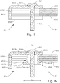
- a leaf-spring compound 2 according to a first embodiment of the invention includes an attachment arrangement 21 at either end of the leaf-spring compound 2.
- a coupling element 211 is provided with an end wall 2111 and two opposite side walls 2112. The coupling element 211 is thereby open to receive an end portion 2153 of one or more leaf springs 215, 215'.
- the coupling element 211 is also provided with a bolt hole 2114 in a bottom portion 2113. In the end wall 2111, the coupling element 211 is provided with an end attachment 2115 for connection to the plough.
- a clamping bolt 212 extending through the bolt hole 2114 of the coupling element 211 is provided with engagement means 2121 in the form of several locking-bolt holes.
- the leaf-spring compound 2 includes several leaf springs 215, 215', each provided with a cut-out 2152 (see figure 4 ) having a mouth with a narrowed width at either end portion 2153.
- a plate-shaped supporting element 214 is substantially congruent with the inside of the coupling element 211 and is arranged to rest supportingly against an inner leaf spring 215' of the leaf-spring compound 2.
- a locking bolt 213 forms a stop element and is arranged to engage with one of the locking-bolt holes 2121 in the clamping bolt 212.
- the locking-bolt hole 2121 that gives a moderate mutual clearance between the end portions 2153 of the leaf springs 215, 215' is preferably chosen.
- the locking bolt 213 is secured against falling out by means of a securing means 2142, shown here as a spring pin extending through a securing-means hole 2131 in the locking bolt 213.
- the leaf-spring compound 2 according to a second embodiment of the invention includes an attachment arrangement 21 at either end of the leaf-spring compound 2.
- the coupling element 211 is as described above.
- the clamping bolt 212 projecting through the bolt hole 2114 of the coupling element 211 is provided with an engagement means 2121 in the form of a threaded portion.
- the leaf-spring compound 2 includes several leaf springs 215, 215', each provided with a cut-out 2152 having a mouth with a narrowed width at either end portion 2153.
- the cut-out 2152 has a transverse dimension W (see figure 4 ).
- a sleeve-shaped supporting element 214 includes a projecting end portion 2142 with a diameter D 3 (see figure 6 in particular). Opposite the projecting end portion 2141, an end portion forms a first abutment surface 2144 arranged to abut against the coupling element 211. The projecting end portion 2141 forms a second abutment surface 2145, which is arranged to abut against the end portion 2153 of the inner leaf spring 215' of the leaf-spring compound 2. Internally, the supporting element 214 is provided with a threaded portion 2143. The cylindrical portion has a diameter D 1 which is smaller than the transverse dimension W of the leaf-spring cut-outs 2152. From the abutment surface 2145 of the projecting end portion 2141, a securing means 2142 in the form of a peg arranged to engage with the cut-out 2152 projects in the axial direction.
- a stop means 213 in the form of a nut is provided with an internal threaded portion 2137 arranged to engage with the clamping bolt 212.
- the nut 213 is also provided with an external threaded portion 2136 arranged to engage with the sleeve-shaped supporting element 214.
- the nut 213 also includes a projecting portion 2133 with a diameter D 2 , which is larger than the diameter of the threaded portion 2143 of the supporting element 214 and forms an abutment surface 2134 that may abut against the projecting end portion 2141 of the supporting element 214.
- the nut 213 includes a coupling portion 2135 arranged to receive a tightening tool (not shown), for example an open-end spanner.
- the external threaded portion 2136 has a larger thread pitch than the internal threaded portion 2137. This gives the effect, when the nut 213 is being screwed in, of the supporting element 214 being lifted a little so that a certain clearance forms between the second abutment surface 2145 of the supporting element 2145 and the inner leaf spring 215' of the leaf-spring compound 2. Thereby the leaf springs 215, 215' can move relative to each other when the leaf-spring compound 2 is being tensioned in connection with the release system 1 being activated and the leaf springs 215, 215' being curved with different diameters.
Landscapes
- Engineering & Computer Science (AREA)
- General Engineering & Computer Science (AREA)
- Mechanical Engineering (AREA)
- Life Sciences & Earth Sciences (AREA)
- Soil Sciences (AREA)
- Environmental Sciences (AREA)
- Springs (AREA)
- Clamps And Clips (AREA)
- Farming Of Fish And Shellfish (AREA)
- Soil Working Implements (AREA)
- Vibration Prevention Devices (AREA)
Claims (9)
- Un système de fixation (21) comprenant un ensemble de ressorts à lames (2) utilisé comme système de désolidarisation (1), en particulier pour accessoires de travail du sol, l'ensemble de ressorts à lames (2) comprenant plusieurs ressorts à lames (215, 215') avec des plans de sol sensiblement identiques, caractérisé en ce que le système de fixation comprend un élément d'accouplement (211), un boulon de serrage (212), un élément de butée (213) et un élément d'appui (214), et en ce que les ressorts à lames (215, 215') sont retenus ensemble par le système de fixation (21) à chaque partie d'extrémité (2153) des ressorts à lames (215, 215'), où chacune des parties d'extrémité (2153) de chaque ressort à lames (215, 215') vient buter en appui dans l'élément d'accouplement (211) et est fixé à l'élément d'accouplement (211) avec le boulon de serrage (212), l'élément de butée (213) et l'élément d'appui (214), l'élément d'appui (214) créant un espace jusqu'à un ressort à lames interne (215') et étant placé au moins partiellement sur une découpe (2152) dans les ressorts à lames (215, 215').
- Le système de fixation (21) selon la revendication 1, dans lequel l'élément de butée (213) est un boulon verrouillant disposé pour venir en prise avec des moyens de prise (2121) en forme d'un ou plusieurs trous à boulon verrouillant disposés dans le boulon de serrage (212).
- Le système de fixation (21) selon la revendication 1, dans lequel l'élément d'appui (214) est formé comme plaque d'appui complémentaire à l'intérieur de l'élément d'accouplement (211).
- Le système de fixation (21) selon la revendication 1, dans lequel l'élément de butée (213) est un écrou, et la largeur (W) de la découpe (2152) est supérieure au diamètre cylindrique (D1) de l'élément d'appui (214), mais inférieure au diamètre (D3) d'une partie d'extrémité externe faisant saillie (2141) de l'élément d'appui (214), et l'élément d'appui (214) est pourvu d'une partie filetée interne (2143), l'écrou (213) inclut une partie faisant saillie (2133), une partie filetée externe (2136) disposée pour venir en prise avec la partie filetée interne (2143) de l'élément d'appui (214), une partie filetée interne (2137) et une partie d'accouplement (2135) disposées pour venir en prise avec un outil de serrage, le boulon de serrage (212) est pourvu d'une partie de prise disposée pour venir en prise de manière désolidarisable avec l'écrou (213) en forme de partie filetée (2121) disposée pour venir en prise avec la partie filetée interne (2137) de l'écrou (213), et dans lequel la partie filetée externe (2136) de l'écrou (213) possède un pas de vis supérieur à la partie filetée interne (2137) de l'écrou (213).
- Le système de fixation (21) selon la revendication 4, dans lequel la partie d'accouplement (2135) consiste de la partie faisant saillie (2133) de l'écrou (213).
- Le système de fixation (21) selon la revendication 4, dans lequel la partie d'accouplement (2135) consiste d'une seconde partie d'extrémité (2135') de l'écrou (213).
- Le système de fixation (21) selon la revendication 1, dans lequel l'élément d'appui (214) est pourvu d'un moyen de sécurisation (2142).
- Le système de fixation (21) selon la revendication 7, dans lequel le moyen de sécurisation (2142) est une broche disposée dans la partie d'extrémité faisant saillie (2141) de l'élément d'appui (214) et disposée pour venir en prise avec une partie de la découpe (2152) qui a son embouchure dans les parties d'extrémité (2153) des ressorts à lames (215, 215')
- Le système de fixation (21) selon la revendication 7, dans lequel le moyen de sécurisation (2142) est une broche à ressorts disposée dans un trou de moyen de sécurisation (2131) dans le boulon verrouillant (213).
Applications Claiming Priority (2)
| Application Number | Priority Date | Filing Date | Title |
|---|---|---|---|
| NO20131385A NO336586B1 (no) | 2013-10-18 | 2013-10-18 | Festearrangement for bladfjørsammenstilling |
| PCT/NO2014/050190 WO2015057079A1 (fr) | 2013-10-18 | 2014-10-08 | Système de fixation pour ensemble de ressorts à lames |
Publications (3)
| Publication Number | Publication Date |
|---|---|
| EP3057397A1 EP3057397A1 (fr) | 2016-08-24 |
| EP3057397A4 EP3057397A4 (fr) | 2017-06-21 |
| EP3057397B1 true EP3057397B1 (fr) | 2019-03-06 |
Family
ID=52828420
Family Applications (1)
| Application Number | Title | Priority Date | Filing Date |
|---|---|---|---|
| EP14853390.4A Not-in-force EP3057397B1 (fr) | 2013-10-18 | 2014-10-08 | Système de fixation pour ensemble de ressorts à lames |
Country Status (8)
| Country | Link |
|---|---|
| US (1) | US10132377B2 (fr) |
| EP (1) | EP3057397B1 (fr) |
| CN (1) | CN105899066B (fr) |
| AU (1) | AU2014335014B2 (fr) |
| CA (1) | CA2927563A1 (fr) |
| EA (1) | EA031081B1 (fr) |
| NO (1) | NO336586B1 (fr) |
| WO (1) | WO2015057079A1 (fr) |
Families Citing this family (2)
| Publication number | Priority date | Publication date | Assignee | Title |
|---|---|---|---|---|
| RU2701690C2 (ru) * | 2018-02-22 | 2019-09-30 | Федеральное государственное бюджетное образовательное учреждение высшего образования "Горский государственный аграрный университет" | Секция оборотного плуга с регулируемыми композитными упругими звеньями предохранителя |
| RU192095U1 (ru) * | 2019-05-17 | 2019-09-03 | Федеральное государственное бюджетное образовательное Учреждение высшего образования "Воронежский государственный аграрный университет имени императора Петра I" (ФГБОУ ВО Воронежский ГАУ) | Оборотный плуг с вибрирующими корпусами |
Family Cites Families (52)
| Publication number | Priority date | Publication date | Assignee | Title |
|---|---|---|---|---|
| US38661A (en) * | 1863-05-26 | Improvement in car-springs | ||
| US720914A (en) * | 1902-03-20 | 1903-02-17 | James P Doane | Separable band for leaf-springs. |
| US945336A (en) * | 1908-08-03 | 1910-01-04 | Charles A Lieb | Spring. |
| US999826A (en) * | 1910-12-30 | 1911-08-08 | Randolph M Mcgahee | Vehicle-spring. |
| US1169473A (en) * | 1914-07-23 | 1916-01-25 | Gen Motors Corp | Vehicle-frame. |
| US1929796A (en) * | 1929-05-29 | 1933-10-10 | Gen Motors Corp | Flexible spring shackle mounting |
| US1829163A (en) * | 1929-12-23 | 1931-10-27 | Us Spring And Bumper Company I | Vehicle spring construction |
| US2539091A (en) * | 1947-06-27 | 1951-01-23 | Frank E Linke | Spring mounting for automotive vehicles |
| US2762622A (en) * | 1953-02-13 | 1956-09-11 | Ne Peer Company | Spring end shackle |
| US2772891A (en) * | 1955-04-01 | 1956-12-04 | Fred D Bonnin | Vehicle spring and end connection arrangement |
| US3010744A (en) * | 1957-03-27 | 1961-11-28 | Pittsburgh Forging Co | Tractor attachments |
| US3074738A (en) * | 1960-07-08 | 1963-01-22 | Webb Metal Products Co | Axle suspension unit |
| US3173668A (en) * | 1962-05-17 | 1965-03-16 | Cambria Spring Co | Adjustable overload bracket for vehicles |
| US3243198A (en) * | 1962-05-28 | 1966-03-29 | Champ Corp | Trunnion suspension |
| DK99956C (da) * | 1963-05-15 | 1964-10-05 | A Andersens Staalvarefabrik As | Spændebø jle til sammenspænding af en fjedrende harvetands fjederdel med tandens skærarm. |
| US3494608A (en) * | 1967-12-15 | 1970-02-10 | Dura Corp | Suspension |
| US3767222A (en) * | 1971-11-09 | 1973-10-23 | E Willetts | Vehicle suspension structure |
| BE793066A (fr) * | 1971-12-20 | 1973-04-16 | Tunesi Roger | Stabilisateur et anti-lacets pour caravanes et remorques routieres |
| NO134354C (fr) * | 1972-02-01 | 1976-09-29 | Kvernelands Fab As | |
| US3891197A (en) * | 1973-10-15 | 1975-06-24 | Gus L Poulos | Single leaf spring |
| US3910354A (en) | 1974-07-26 | 1975-10-07 | Int Harvester Co | Toggle trip for moldboard plow |
| US3964600A (en) | 1974-10-17 | 1976-06-22 | Fmc Corporation | Natural frequency adjustment for vibratory feeder |
| US3964735A (en) * | 1975-03-03 | 1976-06-22 | Wright Oliver L | Torsion bar adaptor for vehicle springs |
| DE2850226C2 (de) * | 1978-11-20 | 1980-09-18 | Amazonen-Werke H. Dreyer Gmbh & Co Kg, 4507 Hasbergen | Bodenbearbeitungsmaschine |
| US4313620A (en) * | 1979-09-10 | 1982-02-02 | Fred Posnikoff | Device for limiting lateral canting of road vehicles |
| US4322061A (en) * | 1980-02-14 | 1982-03-30 | Lear Siegler, Inc. | Tandem spring suspension with leaf rotation stop |
| US4502707A (en) * | 1983-06-06 | 1985-03-05 | Boler Investments, Inc. | Tandem axle suspension system |
| NL8402540A (nl) | 1984-08-20 | 1986-03-17 | Lely Nv C Van Der | Ploeg. |
| US4630804A (en) * | 1985-01-07 | 1986-12-23 | Ford Motor Company | Leaf spring clamp for synthetic material leaf spring |
| DE3503135C2 (de) | 1985-01-31 | 1993-12-16 | Lemken Kg Pflugfab | Pflug mit halbautomatischer Überlastsicherung |
| EP0199406B1 (fr) | 1985-04-11 | 1989-10-18 | C. van der Lely N.V. | Charrue |
| US4691645A (en) * | 1985-07-05 | 1987-09-08 | Steven Anderson | Seed planter attachment |
| DE3613804C1 (de) * | 1986-04-24 | 1987-07-09 | Audi Ag | Vorrichtung mit einem flaechigem Bauteil aus faserverstaerktem Kunststoff und einem endseitigen Krafteinleitungsteil |
| US4860672A (en) * | 1987-04-30 | 1989-08-29 | Robert Zimmerman | Trip mechanism for drill seed boot |
| FR2623964A1 (fr) * | 1987-12-08 | 1989-06-09 | Mach Agricoles Cie Fse | Perfectionnements aux charrues |
| AT389415B (de) | 1988-06-10 | 1989-12-11 | Vogel & Noot Landmasch | Pfluganordnung |
| US5154239A (en) * | 1991-06-10 | 1992-10-13 | Harrell Equipment Company, Inc. | Reversible plow with spring-biased trip shanks |
| US5251886A (en) * | 1992-05-14 | 1993-10-12 | Bursel Joseph S | Semi-elliptical spring suspension with automatic spring rate varying capacity |
| US5335934A (en) * | 1993-05-26 | 1994-08-09 | Ez Loader Boat Trailers, Inc. | Spring hanger assembly for trailer frame |
| US7753399B2 (en) * | 2005-08-22 | 2010-07-13 | Lippert Components, Inc. | Equalizer for a suspension system |
| US7296821B2 (en) * | 2005-08-22 | 2007-11-20 | Lippert Components Manufacturing, Inc. | Equalizer for a suspension system |
| CA2553518A1 (fr) * | 2005-09-14 | 2007-03-14 | Standens Ltd. | Ensemble de ressorts a lames pourvu d'un ressort de securite avec elements de retenue |
| US7360778B2 (en) * | 2005-10-13 | 2008-04-22 | Smith Kim H | Traction device |
| CN201518569U (zh) * | 2009-03-31 | 2010-07-07 | 新疆农垦科学院 | 翻转双向超深耕犁 |
| US20110057409A1 (en) | 2009-09-09 | 2011-03-10 | International Truck Intellectual Property Company, Llc | Dual Load Path Suspension Assembly with Auxiliary Roll Stiffness |
| US8327780B2 (en) * | 2009-10-16 | 2012-12-11 | Dawn Equipment Company | Agricultural implement having fluid delivery features |
| US8365837B2 (en) * | 2009-12-09 | 2013-02-05 | Salford Farm Machinery Ltd. | Resiliently mounted agricultural tool and implement therewith |
| JP5620755B2 (ja) * | 2010-08-31 | 2014-11-05 | 日野自動車株式会社 | サスペンション装置 |
| DE102011081693A1 (de) * | 2011-08-29 | 2013-02-28 | Zf Friedrichshafen Ag | Halterung für eine Feder |
| US8820760B2 (en) * | 2011-12-28 | 2014-09-02 | Vdl Weweler B.V. | Wheel axle suspension |
| BR102012031693A2 (pt) * | 2012-12-12 | 2014-09-02 | Suspensys Sist S Automotivos Ltda | Suportes centrais e balancins para suspensão tandem |
| DE102014012652A1 (de) * | 2014-08-21 | 2016-02-25 | Brose Fahrzeugteile Gmbh & Co. Kommanditgesellschaft, Hallstadt | Elektronische Baueinheit, insbesondere kapazitiver Näherungssensor für ein Fahrzeug |
-
2013
- 2013-10-18 NO NO20131385A patent/NO336586B1/no not_active IP Right Cessation
-
2014
- 2014-10-08 US US15/029,760 patent/US10132377B2/en not_active Expired - Fee Related
- 2014-10-08 EA EA201690664A patent/EA031081B1/ru not_active IP Right Cessation
- 2014-10-08 WO PCT/NO2014/050190 patent/WO2015057079A1/fr not_active Ceased
- 2014-10-08 EP EP14853390.4A patent/EP3057397B1/fr not_active Not-in-force
- 2014-10-08 CN CN201480057359.0A patent/CN105899066B/zh not_active Expired - Fee Related
- 2014-10-08 AU AU2014335014A patent/AU2014335014B2/en not_active Ceased
- 2014-10-08 CA CA2927563A patent/CA2927563A1/fr not_active Abandoned
Non-Patent Citations (1)
| Title |
|---|
| None * |
Also Published As
| Publication number | Publication date |
|---|---|
| CN105899066B (zh) | 2018-12-21 |
| EP3057397A1 (fr) | 2016-08-24 |
| WO2015057079A1 (fr) | 2015-04-23 |
| CN105899066A (zh) | 2016-08-24 |
| US10132377B2 (en) | 2018-11-20 |
| CA2927563A1 (fr) | 2015-04-23 |
| EA031081B1 (ru) | 2018-11-30 |
| AU2014335014B2 (en) | 2016-12-15 |
| US20160245355A1 (en) | 2016-08-25 |
| NO20131385A1 (no) | 2015-04-20 |
| EA201690664A1 (ru) | 2016-10-31 |
| EP3057397A4 (fr) | 2017-06-21 |
| NO336586B1 (no) | 2015-09-28 |
Similar Documents
| Publication | Publication Date | Title |
|---|---|---|
| CA2890557C (fr) | Systemes et methodes portant sur un compresseur amortisseur de direction | |
| CN105059456B (zh) | 自行车车把夹具组件 | |
| US10463916B2 (en) | Active camming device | |
| ES2646944T3 (es) | Cajón con armaduras laterales y un panel frontal regulable | |
| US20160215805A1 (en) | Anchor bolt | |
| AU2014335014B2 (en) | Attachment arrangement for a leaf spring compound | |
| AU2014335014A1 (en) | Attachment arrangement for a leaf spring compound | |
| CN102523771A (zh) | 用于农用拖拉机的连杆的稳定器 | |
| CA2489068C (fr) | Goupille d'attelage | |
| CZ45097A3 (en) | Lifting rod for connecting lower guide of a tractor three point superstructure | |
| KR200456245Y1 (ko) | 써레 장착용 구조물 | |
| US20170114949A1 (en) | Guide rail assembly as well as guide rail holder | |
| JP6192555B2 (ja) | タイロッド用連結具 | |
| JP3136522U (ja) | 可変式バール | |
| ES2307200T3 (es) | Equipo regulador para un freno de estacionamiento. | |
| EP2992747B1 (fr) | Dispositif de fixation pour une barre inférieure d'un attelage trois point d'un tracteur agricole | |
| EP2437998A1 (fr) | Élément de tension | |
| KR200466401Y1 (ko) | 길이조절기능을 구비한 지지와이어 | |
| ES2648973T3 (es) | Listón de arado quitanieves con deflector de bordillo y procedimiento para conectar un deflector de bordillo a un listón de arado quitanieves | |
| SE1051264A1 (sv) | Jordbearbetande verktyg för löstagbar fixering på ett lantbruksredskap samt lantbruksredskap omfattande sådant jordbearbetande verktyg | |
| SE532989C2 (sv) | Kultivator med fram- och bakåtvända jordbearbetande verktyg på samma balk | |
| AR025842A1 (es) | Soporte para disparo de resorte que tiene fuerzas de pandeo de resorte reducidas | |
| US20020153206A1 (en) | Brake tensioner | |
| JP2018113805A (ja) | 支線張力調整器 | |
| EP2206426A2 (fr) | Séparation de logettes |
Legal Events
| Date | Code | Title | Description |
|---|---|---|---|
| PUAI | Public reference made under article 153(3) epc to a published international application that has entered the european phase |
Free format text: ORIGINAL CODE: 0009012 |
|
| 17P | Request for examination filed |
Effective date: 20160405 |
|
| AK | Designated contracting states |
Kind code of ref document: A1 Designated state(s): AL AT BE BG CH CY CZ DE DK EE ES FI FR GB GR HR HU IE IS IT LI LT LU LV MC MK MT NL NO PL PT RO RS SE SI SK SM TR |
|
| AX | Request for extension of the european patent |
Extension state: BA ME |
|
| DAX | Request for extension of the european patent (deleted) | ||
| A4 | Supplementary search report drawn up and despatched |
Effective date: 20170518 |
|
| RIC1 | Information provided on ipc code assigned before grant |
Ipc: A01B 61/04 20060101AFI20170512BHEP |
|
| STAA | Information on the status of an ep patent application or granted ep patent |
Free format text: STATUS: EXAMINATION IS IN PROGRESS |
|
| 17Q | First examination report despatched |
Effective date: 20170830 |
|
| GRAP | Despatch of communication of intention to grant a patent |
Free format text: ORIGINAL CODE: EPIDOSNIGR1 |
|
| STAA | Information on the status of an ep patent application or granted ep patent |
Free format text: STATUS: GRANT OF PATENT IS INTENDED |
|
| INTG | Intention to grant announced |
Effective date: 20181004 |
|
| RIN1 | Information on inventor provided before grant (corrected) |
Inventor name: TIME, EYVIND |
|
| GRAS | Grant fee paid |
Free format text: ORIGINAL CODE: EPIDOSNIGR3 |
|
| GRAA | (expected) grant |
Free format text: ORIGINAL CODE: 0009210 |
|
| STAA | Information on the status of an ep patent application or granted ep patent |
Free format text: STATUS: THE PATENT HAS BEEN GRANTED |
|
| AK | Designated contracting states |
Kind code of ref document: B1 Designated state(s): AL AT BE BG CH CY CZ DE DK EE ES FI FR GB GR HR HU IE IS IT LI LT LU LV MC MK MT NL NO PL PT RO RS SE SI SK SM TR |
|
| REG | Reference to a national code |
Ref country code: GB Ref legal event code: FG4D |
|
| REG | Reference to a national code |
Ref country code: CH Ref legal event code: EP Ref country code: AT Ref legal event code: REF Ref document number: 1103314 Country of ref document: AT Kind code of ref document: T Effective date: 20190315 |
|
| REG | Reference to a national code |
Ref country code: DE Ref legal event code: R096 Ref document number: 602014042551 Country of ref document: DE |
|
| REG | Reference to a national code |
Ref country code: IE Ref legal event code: FG4D |
|
| REG | Reference to a national code |
Ref country code: NL Ref legal event code: MP Effective date: 20190306 |
|
| REG | Reference to a national code |
Ref country code: LT Ref legal event code: MG4D |
|
| PG25 | Lapsed in a contracting state [announced via postgrant information from national office to epo] |
Ref country code: FI Free format text: LAPSE BECAUSE OF FAILURE TO SUBMIT A TRANSLATION OF THE DESCRIPTION OR TO PAY THE FEE WITHIN THE PRESCRIBED TIME-LIMIT Effective date: 20190306 Ref country code: NO Free format text: LAPSE BECAUSE OF FAILURE TO SUBMIT A TRANSLATION OF THE DESCRIPTION OR TO PAY THE FEE WITHIN THE PRESCRIBED TIME-LIMIT Effective date: 20190606 Ref country code: LT Free format text: LAPSE BECAUSE OF FAILURE TO SUBMIT A TRANSLATION OF THE DESCRIPTION OR TO PAY THE FEE WITHIN THE PRESCRIBED TIME-LIMIT Effective date: 20190306 Ref country code: SE Free format text: LAPSE BECAUSE OF FAILURE TO SUBMIT A TRANSLATION OF THE DESCRIPTION OR TO PAY THE FEE WITHIN THE PRESCRIBED TIME-LIMIT Effective date: 20190306 |
|
| PG25 | Lapsed in a contracting state [announced via postgrant information from national office to epo] |
Ref country code: LV Free format text: LAPSE BECAUSE OF FAILURE TO SUBMIT A TRANSLATION OF THE DESCRIPTION OR TO PAY THE FEE WITHIN THE PRESCRIBED TIME-LIMIT Effective date: 20190306 Ref country code: NL Free format text: LAPSE BECAUSE OF FAILURE TO SUBMIT A TRANSLATION OF THE DESCRIPTION OR TO PAY THE FEE WITHIN THE PRESCRIBED TIME-LIMIT Effective date: 20190306 Ref country code: RS Free format text: LAPSE BECAUSE OF FAILURE TO SUBMIT A TRANSLATION OF THE DESCRIPTION OR TO PAY THE FEE WITHIN THE PRESCRIBED TIME-LIMIT Effective date: 20190306 Ref country code: GR Free format text: LAPSE BECAUSE OF FAILURE TO SUBMIT A TRANSLATION OF THE DESCRIPTION OR TO PAY THE FEE WITHIN THE PRESCRIBED TIME-LIMIT Effective date: 20190607 Ref country code: BG Free format text: LAPSE BECAUSE OF FAILURE TO SUBMIT A TRANSLATION OF THE DESCRIPTION OR TO PAY THE FEE WITHIN THE PRESCRIBED TIME-LIMIT Effective date: 20190606 Ref country code: HR Free format text: LAPSE BECAUSE OF FAILURE TO SUBMIT A TRANSLATION OF THE DESCRIPTION OR TO PAY THE FEE WITHIN THE PRESCRIBED TIME-LIMIT Effective date: 20190306 |
|
| REG | Reference to a national code |
Ref country code: AT Ref legal event code: MK05 Ref document number: 1103314 Country of ref document: AT Kind code of ref document: T Effective date: 20190306 |
|
| PG25 | Lapsed in a contracting state [announced via postgrant information from national office to epo] |
Ref country code: ES Free format text: LAPSE BECAUSE OF FAILURE TO SUBMIT A TRANSLATION OF THE DESCRIPTION OR TO PAY THE FEE WITHIN THE PRESCRIBED TIME-LIMIT Effective date: 20190306 Ref country code: AL Free format text: LAPSE BECAUSE OF FAILURE TO SUBMIT A TRANSLATION OF THE DESCRIPTION OR TO PAY THE FEE WITHIN THE PRESCRIBED TIME-LIMIT Effective date: 20190306 Ref country code: PT Free format text: LAPSE BECAUSE OF FAILURE TO SUBMIT A TRANSLATION OF THE DESCRIPTION OR TO PAY THE FEE WITHIN THE PRESCRIBED TIME-LIMIT Effective date: 20190706 Ref country code: SK Free format text: LAPSE BECAUSE OF FAILURE TO SUBMIT A TRANSLATION OF THE DESCRIPTION OR TO PAY THE FEE WITHIN THE PRESCRIBED TIME-LIMIT Effective date: 20190306 Ref country code: IT Free format text: LAPSE BECAUSE OF FAILURE TO SUBMIT A TRANSLATION OF THE DESCRIPTION OR TO PAY THE FEE WITHIN THE PRESCRIBED TIME-LIMIT Effective date: 20190306 Ref country code: EE Free format text: LAPSE BECAUSE OF FAILURE TO SUBMIT A TRANSLATION OF THE DESCRIPTION OR TO PAY THE FEE WITHIN THE PRESCRIBED TIME-LIMIT Effective date: 20190306 Ref country code: CZ Free format text: LAPSE BECAUSE OF FAILURE TO SUBMIT A TRANSLATION OF THE DESCRIPTION OR TO PAY THE FEE WITHIN THE PRESCRIBED TIME-LIMIT Effective date: 20190306 Ref country code: RO Free format text: LAPSE BECAUSE OF FAILURE TO SUBMIT A TRANSLATION OF THE DESCRIPTION OR TO PAY THE FEE WITHIN THE PRESCRIBED TIME-LIMIT Effective date: 20190306 |
|
| PG25 | Lapsed in a contracting state [announced via postgrant information from national office to epo] |
Ref country code: SM Free format text: LAPSE BECAUSE OF FAILURE TO SUBMIT A TRANSLATION OF THE DESCRIPTION OR TO PAY THE FEE WITHIN THE PRESCRIBED TIME-LIMIT Effective date: 20190306 Ref country code: PL Free format text: LAPSE BECAUSE OF FAILURE TO SUBMIT A TRANSLATION OF THE DESCRIPTION OR TO PAY THE FEE WITHIN THE PRESCRIBED TIME-LIMIT Effective date: 20190306 |
|
| REG | Reference to a national code |
Ref country code: DE Ref legal event code: R097 Ref document number: 602014042551 Country of ref document: DE |
|
| PG25 | Lapsed in a contracting state [announced via postgrant information from national office to epo] |
Ref country code: IS Free format text: LAPSE BECAUSE OF FAILURE TO SUBMIT A TRANSLATION OF THE DESCRIPTION OR TO PAY THE FEE WITHIN THE PRESCRIBED TIME-LIMIT Effective date: 20190706 Ref country code: AT Free format text: LAPSE BECAUSE OF FAILURE TO SUBMIT A TRANSLATION OF THE DESCRIPTION OR TO PAY THE FEE WITHIN THE PRESCRIBED TIME-LIMIT Effective date: 20190306 |
|
| PLBE | No opposition filed within time limit |
Free format text: ORIGINAL CODE: 0009261 |
|
| STAA | Information on the status of an ep patent application or granted ep patent |
Free format text: STATUS: NO OPPOSITION FILED WITHIN TIME LIMIT |
|
| PG25 | Lapsed in a contracting state [announced via postgrant information from national office to epo] |
Ref country code: DK Free format text: LAPSE BECAUSE OF FAILURE TO SUBMIT A TRANSLATION OF THE DESCRIPTION OR TO PAY THE FEE WITHIN THE PRESCRIBED TIME-LIMIT Effective date: 20190306 |
|
| 26N | No opposition filed |
Effective date: 20191209 |
|
| PG25 | Lapsed in a contracting state [announced via postgrant information from national office to epo] |
Ref country code: SI Free format text: LAPSE BECAUSE OF FAILURE TO SUBMIT A TRANSLATION OF THE DESCRIPTION OR TO PAY THE FEE WITHIN THE PRESCRIBED TIME-LIMIT Effective date: 20190306 |
|
| PG25 | Lapsed in a contracting state [announced via postgrant information from national office to epo] |
Ref country code: TR Free format text: LAPSE BECAUSE OF FAILURE TO SUBMIT A TRANSLATION OF THE DESCRIPTION OR TO PAY THE FEE WITHIN THE PRESCRIBED TIME-LIMIT Effective date: 20190306 |
|
| PG25 | Lapsed in a contracting state [announced via postgrant information from national office to epo] |
Ref country code: MC Free format text: LAPSE BECAUSE OF FAILURE TO SUBMIT A TRANSLATION OF THE DESCRIPTION OR TO PAY THE FEE WITHIN THE PRESCRIBED TIME-LIMIT Effective date: 20190306 |
|
| REG | Reference to a national code |
Ref country code: CH Ref legal event code: PL |
|
| PG25 | Lapsed in a contracting state [announced via postgrant information from national office to epo] |
Ref country code: LU Free format text: LAPSE BECAUSE OF NON-PAYMENT OF DUE FEES Effective date: 20191008 Ref country code: CH Free format text: LAPSE BECAUSE OF NON-PAYMENT OF DUE FEES Effective date: 20191031 Ref country code: LI Free format text: LAPSE BECAUSE OF NON-PAYMENT OF DUE FEES Effective date: 20191031 |
|
| REG | Reference to a national code |
Ref country code: BE Ref legal event code: MM Effective date: 20191031 |
|
| PG25 | Lapsed in a contracting state [announced via postgrant information from national office to epo] |
Ref country code: BE Free format text: LAPSE BECAUSE OF NON-PAYMENT OF DUE FEES Effective date: 20191031 |
|
| PG25 | Lapsed in a contracting state [announced via postgrant information from national office to epo] |
Ref country code: IE Free format text: LAPSE BECAUSE OF NON-PAYMENT OF DUE FEES Effective date: 20191008 |
|
| PGFP | Annual fee paid to national office [announced via postgrant information from national office to epo] |
Ref country code: DE Payment date: 20201022 Year of fee payment: 7 Ref country code: GB Payment date: 20201022 Year of fee payment: 7 Ref country code: FR Payment date: 20201022 Year of fee payment: 7 |
|
| PG25 | Lapsed in a contracting state [announced via postgrant information from national office to epo] |
Ref country code: CY Free format text: LAPSE BECAUSE OF FAILURE TO SUBMIT A TRANSLATION OF THE DESCRIPTION OR TO PAY THE FEE WITHIN THE PRESCRIBED TIME-LIMIT Effective date: 20190306 |
|
| PG25 | Lapsed in a contracting state [announced via postgrant information from national office to epo] |
Ref country code: MT Free format text: LAPSE BECAUSE OF FAILURE TO SUBMIT A TRANSLATION OF THE DESCRIPTION OR TO PAY THE FEE WITHIN THE PRESCRIBED TIME-LIMIT Effective date: 20190306 Ref country code: HU Free format text: LAPSE BECAUSE OF FAILURE TO SUBMIT A TRANSLATION OF THE DESCRIPTION OR TO PAY THE FEE WITHIN THE PRESCRIBED TIME-LIMIT; INVALID AB INITIO Effective date: 20141008 |
|
| REG | Reference to a national code |
Ref country code: DE Ref legal event code: R119 Ref document number: 602014042551 Country of ref document: DE |
|
| GBPC | Gb: european patent ceased through non-payment of renewal fee |
Effective date: 20211008 |
|
| PG25 | Lapsed in a contracting state [announced via postgrant information from national office to epo] |
Ref country code: MK Free format text: LAPSE BECAUSE OF FAILURE TO SUBMIT A TRANSLATION OF THE DESCRIPTION OR TO PAY THE FEE WITHIN THE PRESCRIBED TIME-LIMIT Effective date: 20190306 |
|
| PG25 | Lapsed in a contracting state [announced via postgrant information from national office to epo] |
Ref country code: GB Free format text: LAPSE BECAUSE OF NON-PAYMENT OF DUE FEES Effective date: 20211008 Ref country code: DE Free format text: LAPSE BECAUSE OF NON-PAYMENT OF DUE FEES Effective date: 20220503 |
|
| PG25 | Lapsed in a contracting state [announced via postgrant information from national office to epo] |
Ref country code: FR Free format text: LAPSE BECAUSE OF NON-PAYMENT OF DUE FEES Effective date: 20211031 |