EP3052353B1 - Verfahren für ein fahrerassistenzsystem eines fahrzeugs - Google Patents
Verfahren für ein fahrerassistenzsystem eines fahrzeugs Download PDFInfo
- Publication number
- EP3052353B1 EP3052353B1 EP14780451.2A EP14780451A EP3052353B1 EP 3052353 B1 EP3052353 B1 EP 3052353B1 EP 14780451 A EP14780451 A EP 14780451A EP 3052353 B1 EP3052353 B1 EP 3052353B1
- Authority
- EP
- European Patent Office
- Prior art keywords
- vehicle
- autopilot
- function
- section
- assistance system
- Prior art date
- Legal status (The legal status is an assumption and is not a legal conclusion. Google has not performed a legal analysis and makes no representation as to the accuracy of the status listed.)
- Active
Links
Images



Classifications
-
- B—PERFORMING OPERATIONS; TRANSPORTING
- B60—VEHICLES IN GENERAL
- B60W—CONJOINT CONTROL OF VEHICLE SUB-UNITS OF DIFFERENT TYPE OR DIFFERENT FUNCTION; CONTROL SYSTEMS SPECIALLY ADAPTED FOR HYBRID VEHICLES; ROAD VEHICLE DRIVE CONTROL SYSTEMS FOR PURPOSES NOT RELATED TO THE CONTROL OF A PARTICULAR SUB-UNIT
- B60W50/00—Details of control systems for road vehicle drive control not related to the control of a particular sub-unit, e.g. process diagnostic or vehicle driver interfaces
- B60W50/08—Interaction between the driver and the control system
- B60W50/14—Means for informing the driver, warning the driver or prompting a driver intervention
-
- G—PHYSICS
- G05—CONTROLLING; REGULATING
- G05D—SYSTEMS FOR CONTROLLING OR REGULATING NON-ELECTRIC VARIABLES
- G05D1/00—Control of position, course, altitude or attitude of land, water, air or space vehicles, e.g. using automatic pilots
- G05D1/0055—Control of position, course, altitude or attitude of land, water, air or space vehicles, e.g. using automatic pilots with safety arrangements
- G05D1/0061—Control of position, course, altitude or attitude of land, water, air or space vehicles, e.g. using automatic pilots with safety arrangements for transition from automatic pilot to manual pilot and vice versa
-
- B—PERFORMING OPERATIONS; TRANSPORTING
- B60—VEHICLES IN GENERAL
- B60K—ARRANGEMENT OR MOUNTING OF PROPULSION UNITS OR OF TRANSMISSIONS IN VEHICLES; ARRANGEMENT OR MOUNTING OF PLURAL DIVERSE PRIME-MOVERS IN VEHICLES; AUXILIARY DRIVES FOR VEHICLES; INSTRUMENTATION OR DASHBOARDS FOR VEHICLES; ARRANGEMENTS IN CONNECTION WITH COOLING, AIR INTAKE, GAS EXHAUST OR FUEL SUPPLY OF PROPULSION UNITS IN VEHICLES
- B60K35/00—Instruments specially adapted for vehicles; Arrangement of instruments in or on vehicles
- B60K35/10—Input arrangements, i.e. from user to vehicle, associated with vehicle functions or specially adapted therefor
-
- B—PERFORMING OPERATIONS; TRANSPORTING
- B60—VEHICLES IN GENERAL
- B60K—ARRANGEMENT OR MOUNTING OF PROPULSION UNITS OR OF TRANSMISSIONS IN VEHICLES; ARRANGEMENT OR MOUNTING OF PLURAL DIVERSE PRIME-MOVERS IN VEHICLES; AUXILIARY DRIVES FOR VEHICLES; INSTRUMENTATION OR DASHBOARDS FOR VEHICLES; ARRANGEMENTS IN CONNECTION WITH COOLING, AIR INTAKE, GAS EXHAUST OR FUEL SUPPLY OF PROPULSION UNITS IN VEHICLES
- B60K35/00—Instruments specially adapted for vehicles; Arrangement of instruments in or on vehicles
- B60K35/20—Output arrangements, i.e. from vehicle to user, associated with vehicle functions or specially adapted therefor
- B60K35/21—Output arrangements, i.e. from vehicle to user, associated with vehicle functions or specially adapted therefor using visual output, e.g. blinking lights or matrix displays
- B60K35/22—Display screens
-
- B—PERFORMING OPERATIONS; TRANSPORTING
- B60—VEHICLES IN GENERAL
- B60K—ARRANGEMENT OR MOUNTING OF PROPULSION UNITS OR OF TRANSMISSIONS IN VEHICLES; ARRANGEMENT OR MOUNTING OF PLURAL DIVERSE PRIME-MOVERS IN VEHICLES; AUXILIARY DRIVES FOR VEHICLES; INSTRUMENTATION OR DASHBOARDS FOR VEHICLES; ARRANGEMENTS IN CONNECTION WITH COOLING, AIR INTAKE, GAS EXHAUST OR FUEL SUPPLY OF PROPULSION UNITS IN VEHICLES
- B60K35/00—Instruments specially adapted for vehicles; Arrangement of instruments in or on vehicles
- B60K35/20—Output arrangements, i.e. from vehicle to user, associated with vehicle functions or specially adapted therefor
- B60K35/28—Output arrangements, i.e. from vehicle to user, associated with vehicle functions or specially adapted therefor characterised by the type of the output information, e.g. video entertainment or vehicle dynamics information; characterised by the purpose of the output information, e.g. for attracting the attention of the driver
-
- B—PERFORMING OPERATIONS; TRANSPORTING
- B60—VEHICLES IN GENERAL
- B60K—ARRANGEMENT OR MOUNTING OF PROPULSION UNITS OR OF TRANSMISSIONS IN VEHICLES; ARRANGEMENT OR MOUNTING OF PLURAL DIVERSE PRIME-MOVERS IN VEHICLES; AUXILIARY DRIVES FOR VEHICLES; INSTRUMENTATION OR DASHBOARDS FOR VEHICLES; ARRANGEMENTS IN CONNECTION WITH COOLING, AIR INTAKE, GAS EXHAUST OR FUEL SUPPLY OF PROPULSION UNITS IN VEHICLES
- B60K35/00—Instruments specially adapted for vehicles; Arrangement of instruments in or on vehicles
- B60K35/20—Output arrangements, i.e. from vehicle to user, associated with vehicle functions or specially adapted therefor
- B60K35/29—Instruments characterised by the way in which information is handled, e.g. showing information on plural displays or prioritising information according to driving conditions
-
- B—PERFORMING OPERATIONS; TRANSPORTING
- B60—VEHICLES IN GENERAL
- B60K—ARRANGEMENT OR MOUNTING OF PROPULSION UNITS OR OF TRANSMISSIONS IN VEHICLES; ARRANGEMENT OR MOUNTING OF PLURAL DIVERSE PRIME-MOVERS IN VEHICLES; AUXILIARY DRIVES FOR VEHICLES; INSTRUMENTATION OR DASHBOARDS FOR VEHICLES; ARRANGEMENTS IN CONNECTION WITH COOLING, AIR INTAKE, GAS EXHAUST OR FUEL SUPPLY OF PROPULSION UNITS IN VEHICLES
- B60K35/00—Instruments specially adapted for vehicles; Arrangement of instruments in or on vehicles
- B60K35/60—Instruments characterised by their location or relative disposition in or on vehicles
-
- B—PERFORMING OPERATIONS; TRANSPORTING
- B60—VEHICLES IN GENERAL
- B60W—CONJOINT CONTROL OF VEHICLE SUB-UNITS OF DIFFERENT TYPE OR DIFFERENT FUNCTION; CONTROL SYSTEMS SPECIALLY ADAPTED FOR HYBRID VEHICLES; ROAD VEHICLE DRIVE CONTROL SYSTEMS FOR PURPOSES NOT RELATED TO THE CONTROL OF A PARTICULAR SUB-UNIT
- B60W30/00—Purposes of road vehicle drive control systems not related to the control of a particular sub-unit, e.g. of systems using conjoint control of vehicle sub-units
- B60W30/10—Path keeping
- B60W30/12—Lane keeping
-
- B—PERFORMING OPERATIONS; TRANSPORTING
- B60—VEHICLES IN GENERAL
- B60W—CONJOINT CONTROL OF VEHICLE SUB-UNITS OF DIFFERENT TYPE OR DIFFERENT FUNCTION; CONTROL SYSTEMS SPECIALLY ADAPTED FOR HYBRID VEHICLES; ROAD VEHICLE DRIVE CONTROL SYSTEMS FOR PURPOSES NOT RELATED TO THE CONTROL OF A PARTICULAR SUB-UNIT
- B60W30/00—Purposes of road vehicle drive control systems not related to the control of a particular sub-unit, e.g. of systems using conjoint control of vehicle sub-units
- B60W30/14—Adaptive cruise control
- B60W30/16—Control of distance between vehicles, e.g. keeping a distance to preceding vehicle
-
- B—PERFORMING OPERATIONS; TRANSPORTING
- B60—VEHICLES IN GENERAL
- B60W—CONJOINT CONTROL OF VEHICLE SUB-UNITS OF DIFFERENT TYPE OR DIFFERENT FUNCTION; CONTROL SYSTEMS SPECIALLY ADAPTED FOR HYBRID VEHICLES; ROAD VEHICLE DRIVE CONTROL SYSTEMS FOR PURPOSES NOT RELATED TO THE CONTROL OF A PARTICULAR SUB-UNIT
- B60W50/00—Details of control systems for road vehicle drive control not related to the control of a particular sub-unit, e.g. process diagnostic or vehicle driver interfaces
- B60W50/0097—Predicting future conditions
-
- B—PERFORMING OPERATIONS; TRANSPORTING
- B60—VEHICLES IN GENERAL
- B60W—CONJOINT CONTROL OF VEHICLE SUB-UNITS OF DIFFERENT TYPE OR DIFFERENT FUNCTION; CONTROL SYSTEMS SPECIALLY ADAPTED FOR HYBRID VEHICLES; ROAD VEHICLE DRIVE CONTROL SYSTEMS FOR PURPOSES NOT RELATED TO THE CONTROL OF A PARTICULAR SUB-UNIT
- B60W50/00—Details of control systems for road vehicle drive control not related to the control of a particular sub-unit, e.g. process diagnostic or vehicle driver interfaces
- B60W50/08—Interaction between the driver and the control system
- B60W50/082—Selecting or switching between different modes of propelling
-
- B—PERFORMING OPERATIONS; TRANSPORTING
- B60—VEHICLES IN GENERAL
- B60W—CONJOINT CONTROL OF VEHICLE SUB-UNITS OF DIFFERENT TYPE OR DIFFERENT FUNCTION; CONTROL SYSTEMS SPECIALLY ADAPTED FOR HYBRID VEHICLES; ROAD VEHICLE DRIVE CONTROL SYSTEMS FOR PURPOSES NOT RELATED TO THE CONTROL OF A PARTICULAR SUB-UNIT
- B60W60/00—Drive control systems specially adapted for autonomous road vehicles
- B60W60/005—Handover processes
- B60W60/0051—Handover processes from occupants to vehicle
-
- B—PERFORMING OPERATIONS; TRANSPORTING
- B60—VEHICLES IN GENERAL
- B60W—CONJOINT CONTROL OF VEHICLE SUB-UNITS OF DIFFERENT TYPE OR DIFFERENT FUNCTION; CONTROL SYSTEMS SPECIALLY ADAPTED FOR HYBRID VEHICLES; ROAD VEHICLE DRIVE CONTROL SYSTEMS FOR PURPOSES NOT RELATED TO THE CONTROL OF A PARTICULAR SUB-UNIT
- B60W60/00—Drive control systems specially adapted for autonomous road vehicles
- B60W60/005—Handover processes
- B60W60/0053—Handover processes from vehicle to occupant
- B60W60/0055—Handover processes from vehicle to occupant only part of driving tasks shifted to occupants
-
- G—PHYSICS
- G01—MEASURING; TESTING
- G01C—MEASURING DISTANCES, LEVELS OR BEARINGS; SURVEYING; NAVIGATION; GYROSCOPIC INSTRUMENTS; PHOTOGRAMMETRY OR VIDEOGRAMMETRY
- G01C21/00—Navigation; Navigational instruments not provided for in groups G01C1/00 - G01C19/00
- G01C21/26—Navigation; Navigational instruments not provided for in groups G01C1/00 - G01C19/00 specially adapted for navigation in a road network
- G01C21/34—Route searching; Route guidance
- G01C21/3407—Route searching; Route guidance specially adapted for specific applications
-
- G—PHYSICS
- G01—MEASURING; TESTING
- G01C—MEASURING DISTANCES, LEVELS OR BEARINGS; SURVEYING; NAVIGATION; GYROSCOPIC INSTRUMENTS; PHOTOGRAMMETRY OR VIDEOGRAMMETRY
- G01C21/00—Navigation; Navigational instruments not provided for in groups G01C1/00 - G01C19/00
- G01C21/26—Navigation; Navigational instruments not provided for in groups G01C1/00 - G01C19/00 specially adapted for navigation in a road network
- G01C21/34—Route searching; Route guidance
- G01C21/36—Input/output arrangements for on-board computers
- G01C21/3691—Retrieval, searching and output of information related to real-time traffic, weather, or environmental conditions
- G01C21/3694—Output thereof on a road map
-
- G—PHYSICS
- G01—MEASURING; TESTING
- G01C—MEASURING DISTANCES, LEVELS OR BEARINGS; SURVEYING; NAVIGATION; GYROSCOPIC INSTRUMENTS; PHOTOGRAMMETRY OR VIDEOGRAMMETRY
- G01C21/00—Navigation; Navigational instruments not provided for in groups G01C1/00 - G01C19/00
- G01C21/26—Navigation; Navigational instruments not provided for in groups G01C1/00 - G01C19/00 specially adapted for navigation in a road network
- G01C21/34—Route searching; Route guidance
- G01C21/36—Input/output arrangements for on-board computers
- G01C21/3697—Output of additional, non-guidance related information, e.g. low fuel level
-
- B—PERFORMING OPERATIONS; TRANSPORTING
- B60—VEHICLES IN GENERAL
- B60K—ARRANGEMENT OR MOUNTING OF PROPULSION UNITS OR OF TRANSMISSIONS IN VEHICLES; ARRANGEMENT OR MOUNTING OF PLURAL DIVERSE PRIME-MOVERS IN VEHICLES; AUXILIARY DRIVES FOR VEHICLES; INSTRUMENTATION OR DASHBOARDS FOR VEHICLES; ARRANGEMENTS IN CONNECTION WITH COOLING, AIR INTAKE, GAS EXHAUST OR FUEL SUPPLY OF PROPULSION UNITS IN VEHICLES
- B60K2360/00—Indexing scheme associated with groups B60K35/00 or B60K37/00 relating to details of instruments or dashboards
- B60K2360/16—Type of output information
- B60K2360/172—Driving mode indication
-
- B—PERFORMING OPERATIONS; TRANSPORTING
- B60—VEHICLES IN GENERAL
- B60K—ARRANGEMENT OR MOUNTING OF PROPULSION UNITS OR OF TRANSMISSIONS IN VEHICLES; ARRANGEMENT OR MOUNTING OF PLURAL DIVERSE PRIME-MOVERS IN VEHICLES; AUXILIARY DRIVES FOR VEHICLES; INSTRUMENTATION OR DASHBOARDS FOR VEHICLES; ARRANGEMENTS IN CONNECTION WITH COOLING, AIR INTAKE, GAS EXHAUST OR FUEL SUPPLY OF PROPULSION UNITS IN VEHICLES
- B60K2360/00—Indexing scheme associated with groups B60K35/00 or B60K37/00 relating to details of instruments or dashboards
- B60K2360/18—Information management
- B60K2360/182—Distributing information between displays
-
- B—PERFORMING OPERATIONS; TRANSPORTING
- B60—VEHICLES IN GENERAL
- B60K—ARRANGEMENT OR MOUNTING OF PROPULSION UNITS OR OF TRANSMISSIONS IN VEHICLES; ARRANGEMENT OR MOUNTING OF PLURAL DIVERSE PRIME-MOVERS IN VEHICLES; AUXILIARY DRIVES FOR VEHICLES; INSTRUMENTATION OR DASHBOARDS FOR VEHICLES; ARRANGEMENTS IN CONNECTION WITH COOLING, AIR INTAKE, GAS EXHAUST OR FUEL SUPPLY OF PROPULSION UNITS IN VEHICLES
- B60K35/00—Instruments specially adapted for vehicles; Arrangement of instruments in or on vehicles
- B60K35/20—Output arrangements, i.e. from vehicle to user, associated with vehicle functions or specially adapted therefor
- B60K35/21—Output arrangements, i.e. from vehicle to user, associated with vehicle functions or specially adapted therefor using visual output, e.g. blinking lights or matrix displays
- B60K35/23—Head-up displays [HUD]
-
- B—PERFORMING OPERATIONS; TRANSPORTING
- B60—VEHICLES IN GENERAL
- B60K—ARRANGEMENT OR MOUNTING OF PROPULSION UNITS OR OF TRANSMISSIONS IN VEHICLES; ARRANGEMENT OR MOUNTING OF PLURAL DIVERSE PRIME-MOVERS IN VEHICLES; AUXILIARY DRIVES FOR VEHICLES; INSTRUMENTATION OR DASHBOARDS FOR VEHICLES; ARRANGEMENTS IN CONNECTION WITH COOLING, AIR INTAKE, GAS EXHAUST OR FUEL SUPPLY OF PROPULSION UNITS IN VEHICLES
- B60K35/00—Instruments specially adapted for vehicles; Arrangement of instruments in or on vehicles
- B60K35/20—Output arrangements, i.e. from vehicle to user, associated with vehicle functions or specially adapted therefor
- B60K35/26—Output arrangements, i.e. from vehicle to user, associated with vehicle functions or specially adapted therefor using acoustic output
-
- B—PERFORMING OPERATIONS; TRANSPORTING
- B60—VEHICLES IN GENERAL
- B60K—ARRANGEMENT OR MOUNTING OF PROPULSION UNITS OR OF TRANSMISSIONS IN VEHICLES; ARRANGEMENT OR MOUNTING OF PLURAL DIVERSE PRIME-MOVERS IN VEHICLES; AUXILIARY DRIVES FOR VEHICLES; INSTRUMENTATION OR DASHBOARDS FOR VEHICLES; ARRANGEMENTS IN CONNECTION WITH COOLING, AIR INTAKE, GAS EXHAUST OR FUEL SUPPLY OF PROPULSION UNITS IN VEHICLES
- B60K35/00—Instruments specially adapted for vehicles; Arrangement of instruments in or on vehicles
- B60K35/50—Instruments characterised by their means of attachment to or integration in the vehicle
- B60K35/53—Movable instruments, e.g. slidable
-
- B—PERFORMING OPERATIONS; TRANSPORTING
- B60—VEHICLES IN GENERAL
- B60W—CONJOINT CONTROL OF VEHICLE SUB-UNITS OF DIFFERENT TYPE OR DIFFERENT FUNCTION; CONTROL SYSTEMS SPECIALLY ADAPTED FOR HYBRID VEHICLES; ROAD VEHICLE DRIVE CONTROL SYSTEMS FOR PURPOSES NOT RELATED TO THE CONTROL OF A PARTICULAR SUB-UNIT
- B60W50/00—Details of control systems for road vehicle drive control not related to the control of a particular sub-unit, e.g. process diagnostic or vehicle driver interfaces
- B60W50/08—Interaction between the driver and the control system
- B60W50/14—Means for informing the driver, warning the driver or prompting a driver intervention
- B60W2050/146—Display means
-
- B—PERFORMING OPERATIONS; TRANSPORTING
- B60—VEHICLES IN GENERAL
- B60W—CONJOINT CONTROL OF VEHICLE SUB-UNITS OF DIFFERENT TYPE OR DIFFERENT FUNCTION; CONTROL SYSTEMS SPECIALLY ADAPTED FOR HYBRID VEHICLES; ROAD VEHICLE DRIVE CONTROL SYSTEMS FOR PURPOSES NOT RELATED TO THE CONTROL OF A PARTICULAR SUB-UNIT
- B60W2556/00—Input parameters relating to data
- B60W2556/45—External transmission of data to or from the vehicle
- B60W2556/50—External transmission of data to or from the vehicle of positioning data, e.g. GPS [Global Positioning System] data
-
- Y—GENERAL TAGGING OF NEW TECHNOLOGICAL DEVELOPMENTS; GENERAL TAGGING OF CROSS-SECTIONAL TECHNOLOGIES SPANNING OVER SEVERAL SECTIONS OF THE IPC; TECHNICAL SUBJECTS COVERED BY FORMER USPC CROSS-REFERENCE ART COLLECTIONS [XRACs] AND DIGESTS
- Y02—TECHNOLOGIES OR APPLICATIONS FOR MITIGATION OR ADAPTATION AGAINST CLIMATE CHANGE
- Y02T—CLIMATE CHANGE MITIGATION TECHNOLOGIES RELATED TO TRANSPORTATION
- Y02T10/00—Road transport of goods or passengers
- Y02T10/80—Technologies aiming to reduce greenhouse gasses emissions common to all road transportation technologies
- Y02T10/84—Data processing systems or methods, management, administration
Definitions
- the present invention relates to a method for a driver assistance system of a vehicle, in particular for a driver assistance system, which is able to control the vehicle at least partially automatically.
- Such functions of a driver assistance system are also referred to as an autopilot function.
- the present invention relates in particular to an information output which relates to the autopilot function or its announcement.
- the present invention further relates to a driver assistance system which is suitable for carrying out the method.
- Modern or future vehicles such as Passenger cars or lorries are increasingly being equipped with driver assistance systems which enable the vehicle to be driven partially or fully automatically. Under certain conditions, these systems can take over both lateral and longitudinal guidance of the vehicle independently.
- a driver of the vehicle does not have to continuously monitor this automatic guidance of the vehicle, which is also referred to as an autopilot function, but can transfer the guidance of the vehicle to the autopilot function or retrieve it at a suitable time.
- the DE 197 43 024 A1 discloses a motor vehicle with autonomous vehicle guidance and electronic communication means.
- An operating device is provided in the vehicle, by means of which the communication means for the purpose of carrying out a communication process and the vehicle guidance means for the purpose of autonomous vehicle guidance can be activated.
- the activated vehicle guidance means transmit a takeover information to the communication means, which display this takeover information on a display device.
- the DE 10 2007 039 375 B4 relates to a motor vehicle with a driver assistance system with a stop & go function.
- the driver assistance system provides longitudinal guidance of the vehicle and comprises a detection device for detecting information relating to a vehicle traveling in front. Depending on the information recorded by means of the detection device, the driver assistance system can automatically insert the motor vehicle into the vehicle Brake the stand and automatically start again when a new approach of the vehicle in front is detected, depending on an actuation signal that can be given by a driver via an input device.
- the DE 10 2010 001 579 A1 relates to a driver assistance system for a vehicle with a device for environmental detection and a device for detecting a current driving situation.
- the driver assistance system calculates a road section ahead in which automatic driving is possible and a driver can therefore carry out a secondary task.
- the driver assistance system tells the driver how long it is likely to take to reach this section of the route, and visually or acoustically notifies him when the time has come to devote himself to the side task.
- the DE 10 2011 082 398 A1 relates to a method for using a driver assistance system.
- the availability of driver assistance systems can depend, for example, on the availability of additional information. In this case, it makes sense to indicate to a driver the route sections of the driving route in which the additional information required is available and in which the driver assistance system is available. This information can be of particular interest, for example, in the case of a fully automatic driving function such as automatic driving.
- Figure 2 shows a schematic representation of a display unit. A road map with the route to be traveled is shown on the display unit. The position of the vehicle is marked with an X. Route sections of the driving route are shown widened on the driving route, in which additional information for a driver assistance system is provided.
- the autopilot function relates to a function of a driver assistance system which is able to automatically control the vehicle at least in certain situations or on certain roads, such as, for example, motorways or country roads.
- the autopilot function takes over the longitudinal guidance and / or the lateral guidance of the vehicle and controls the vehicle without the driver's intervention or intervention. Controlling the vehicle using the autopilot function is also referred to as highly automated driving or autonomous driving.
- a method for a driver assistance system in a vehicle is provided.
- the driver assistance system is able to control the vehicle at least partially automatically.
- the driver assistance system can control the vehicle fully automatically on some sections of the route along a planned route, e.g. on motorway sections or country road sections.
- the automatic control can include, for example, automatic longitudinal guidance and automatic lateral guidance of the vehicle.
- a start of an autopilot route section is determined in a route course planned for the vehicle.
- the planned route can, for example, be specified by a navigation system of the vehicle.
- the driver assistance system is able to control the vehicle automatically.
- the method also determines a distance between a current position of the vehicle and the start of the autopilot route section.
- This distance is output to a driver in the vehicle.
- a driver of the vehicle By outputting the distance to the beginning of the autopilot route section, a driver of the vehicle is shown in a simple manner when the autopilot function will be available. This enables the driver to estimate when he can hand over the management task to the vehicle and can turn to another activity, such as a phone call or studying documents, such as Emails.
- Outputting the distance includes outputting a ring symbol which has a colored or marked ring segment, the extent of which is set as a function of the distance between the current position of the vehicle and the start of the autopilot route section.
- the distance is output on a display device in the vehicle.
- the distance can also be output in text form, for example.
- the text form can, for example, indicate a distance in kilometers to the beginning of the autopilot section.
- an expected travel time to the beginning of the autopilot route section can be determined. This estimated travel time can for example from the distance and a typical traffic situation up to the beginning of the autopilot route section.
- the estimated driving time determined in this way at the beginning of the autopilot route section can, for example, be output in text form on the display device.
- the text form can, for example, include a time in minutes or in minutes and seconds.
- a symbol can be output on the display device, which symbolically represents the expected travel time or the distance.
- the symbol can comprise a bar, which shortens as the distance or the expected travel time decreases.
- a graphical representation of the planned route can be displayed.
- the distance to the start of the autopilot route section can be marked graphically, for example by marking a route to the start of the autopilot route section with a predetermined color.
- the course of the route can also be shown in abstract form in the graphic representation, for example as a straight route.
- acoustic outputs are also possible, for example the distance can be counted down as voice information via an audio system of the vehicle in the form of a countdown.
- a length of the autopilot route section is determined and the length of the autopilot route section is output.
- the driver can estimate how long he can devote himself to another task during the autopilot route section. For example, the driver can accordingly select a task that he is likely to be able to complete in full during the next autopilot route section.
- the length of the autopilot route section can also be output in text form as a kilometer specification, in text form as an expected autopilot travel time, as a symbol or as a graphical representation of the planned route with the autopilot route section marked therein.
- the driver assistance system has an autopilot function which can be activated by a driver for automatic control of the vehicle along the autopilot route section.
- the length of the autopilot route section is shown on a first display device in the Output vehicle or on a second display device in the vehicle.
- the length of the autopilot route section can be displayed on the first display device, for example a display device in a combination instrument, in a region behind a steering wheel of the vehicle when the autopilot function is not activated, and on the second display device, for example on an additional display device, which is used in a, when the autopilot function is activated middle region of the dashboard of the vehicle is arranged.
- the first display device in the instrument cluster shows whether and for how long the autopilot function is available. The driver can use this information to decide whether he would like to hand over the vehicle control to the autopilot function or continue to control the vehicle himself.
- the length of the autopilot route section is shown on the second display device. This provides a clear separation of the vehicle guidance by the driver or the autopilot function.
- other occupants of the vehicle can easily see from the representation of the length of the autopilot route section on the second display device that the vehicle is controlled by the autopilot function and that the driver is therefore allowed to take up a different occupation.
- a future driving maneuver which is planned by the driver assistance system during automatic control of the vehicle, is shown on a display device in the vehicle.
- the future driving maneuver can include, for example, changing lanes, turning, braking or accelerating the vehicle.
- the acceptance of the use of the autopilot function by a driver of the vehicle or by the occupants of the vehicle can be increased by displaying the future driving maneuvers on the display device, in particular on the second display device.
- a traffic situation around the vehicle as detected by the driver assistance system for automatically controlling the vehicle, can be determined and displayed on a display device of the vehicle, in particular on the second display device, for example in connection with the future driving maneuvers.
- the display of the environmental information can increase the confidence that a driver and the passengers of the vehicle have in the autopilot function, by the driver assistance system clearly showing which environmental information is recorded and thus taken into account.
- a driver can get an overview of the current traffic situation by looking at the display device, which can be advantageous if driving responsibility is brought back to the driver.
- the future driving maneuver or the traffic situation around the vehicle is optionally output on the first display device or on the second display device depending on the activation state of the autopilot function.
- future driving maneuvers and the traffic situation around the vehicle can be displayed on the first display device in the instrument cluster of the vehicle when the autopilot function is switched off and on the second display device in the middle area of the dashboard when the autopilot is switched on. This enables a driver to judge whether the autopilot function adequately captures the traffic situation when the autopilot function is switched off, which can increase confidence in the autopilot function.
- the autopilot function is activated, the driver and other occupants of the vehicle can follow and evaluate the functioning of the autopilot function, which in turn can build trust in the autopilot function or a driver can intervene quickly in the vehicle guidance if necessary.
- a message is output as to how the autopilot function can or should be activated.
- the information can be, for example, an electronically displayed information board in a display in the instrument cluster of the vehicle.
- the notice can include, for example, a pictorial representation which shows control elements of the vehicle which are to be actuated to activate the autopilot function. Alternatively or additionally, an acoustic message can be issued.
- operating steps with a certain complexity are usually required to activate or deactivate the autopilot function.
- an end of the autopilot route section is determined in the route course planned for the vehicle.
- a distance between the current position of the vehicle and the end of the autopilot route section is also determined. If the vehicle is operated along the autopilot route section with the autopilot function activated, depending on the distance between the current position of the vehicle and the end of the autopilot route section, a message is output to deactivate the autopilot function.
- the message can be output a few 100 meters before the end of the autopilot section or a specific time, for example 30 seconds before the end of the autopilot section.
- the note can include more precise operating instructions which instruct the driver how to deactivate the autopilot function.
- the information can include, for example, a counter in the form of a countdown, which indicates the remaining distance between the current position of the vehicle and the end of the autopilot route section.
- a counter in the form of a countdown, which indicates the remaining distance between the current position of the vehicle and the end of the autopilot route section.
- a driver assistance system for a vehicle is also provided.
- the driver assistance system is able to control the vehicle at least partially automatically.
- the driver assistance system comprises an output device and a processing device.
- the processing device is able to determine a start of an autopilot route section in a route course planned for the vehicle.
- the driver assistance system can automatically control the vehicle in the autopilot section.
- the processing device is further configured to determine a distance between a current position of the vehicle and the start of the autopilot route section and to output the distance on the output device.
- the processing device is designed to output the distance as a ring symbol which has a colored or marked ring segment, the extent of which is set as a function of the distance between the current position of the vehicle and the start of the autopilot route section.
- the driver assistance system is therefore suitable for carrying out the method and its embodiments described above and therefore also includes the advantages described above.
- a vehicle which comprises the driver assistance system described above and is therefore able to be controlled at least partially automatically.
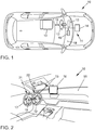
- Fig. 1 shows a vehicle 10 with a driver assistance system 11.
- the vehicle 10 further comprises a steering wheel 12 and a driver seat 13.
- the driver assistance system 11 comprises a control device 14, a first display device 15 and a second display device 16.
- the processing device 14 is provided with the first and second display devices 15, 16 and the steering wheel 12 coupled.
- the first display device 15 is arranged, for example, in an instrument cluster which, from the perspective of a driver sitting on the driver's seat 13, is arranged behind the steering wheel 12.
- the second display device 16 is arranged, for example, approximately centrally in the vehicle transverse direction in a dashboard 18 of the vehicle 10.
- the driver assistance system 11 is able to control the vehicle 10 at least partially automatically, for example by the driver assistance system 14 having both lateral guidance and longitudinal guidance of the vehicle 10 along some route sections Route controls. As a result, the driver assistance system 11 is able to control the vehicle 10 at least in certain situations without driver activity.
- the functionality of the driver assistance system 11 for automatically controlling the vehicle 10 is referred to below as the autopilot function.
- the autopilot function can be activated or deactivated, for example, by actuating corresponding control elements on the steering wheel 12.
- the autopilot function can be activated by manually pushing the steering wheel 12 away from the driver in the direction of the dashboard 18 and the autopilot function can be deactivated by manually pulling the steering wheel 12 away from the dashboard 18 again towards the driver. This movement of the steering wheel 12 is in the 1 and 2 indicated by arrow 19.
- Fig. 2 schematically shows a perspective view of an interior of the vehicle 10.
- the steering wheel 12 can be moved into a first position 21 or a second position 22 by moving the steering wheel 12 in the direction of the arrow 19 in order to deactivate or autopilot the driver assistance system 11 or to activate.
- the first display device 15 and the second display device 16 are shown.
- the first display device 15 can be implemented, for example, as a display in what is known as a freely programmable combination display.
- the first display device 15 can also comprise a display which is superimposed on a windshield of the vehicle, a so-called head-up display.
- Fig. 3 shows method steps 31-40 of a method 30 which are carried out by the processing device 14.
- the method is based on a manual driving operation, ie the vehicle 10 is guided manually by a driver of the vehicle 10.
- a navigation system of the vehicle 10 has determined a route to a destination, for example, or has determined a predicted travel route of the vehicle 10 in any other manner.
- On the first display device 15 in the instrument cluster or in the head-up display normal information for the driver, for example a speed of the vehicle, a fuel level, a current engine speed, etc., is shown.
- additional information for a future autopilot drive is displayed.
- an autopilot route section is determined in step 31, along which the driver assistance system 11 is likely to be able to automatically control the vehicle 10.
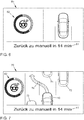
- step 32 a distance from the start of this autopilot route section is determined on the basis of a current position of the vehicle 10. This distance from the start of the autopilot route section is output in step 33 on the first display device 15. Fig. 4 shows such an output 41 of step 33.
- Fig. 4 the distance to the autopilot route section is shown in the output 41 in various ways.
- the vehicle 10 is shown schematically in the direction of travel and a future route to a preceding vehicle 44 is displayed, which is divided into a first portion 42 up to the beginning of the autopilot route section and a second portion 43, which represents the autopilot route section.
- the first portion 42 thus shortens until the beginning of the autopilot route section 43 is reached.
- a textual output 47 is provided on the output 41, in which the time until the beginning of the autopilot route section 43 is reached, taking into account, for example, normal traffic conditions.
- the autopilot function is available in 10 minutes.
- a ring symbol 45 is shown on the output 41, which has a colored or marked ring segment 46, which is enlarged depending on the approach to the beginning of the autopilot route section 43 until the autopilot route section is reached and the ring segment 46 occupies the entire ring.
- the abstracted route 42, 43 thus schematically indicates from which route position the autopilot function can be activated.
- Both the textual representation 47 and the symbolic representation 45 illustrate how long it is still necessary to drive manually.
- the forecasted availability display can be based on route-based data in order to avoid an all too frequent adjustment in the course of the journey.
- the first section 42 can have a different color than the second section 43.
- the symbol 45 can assume a corresponding color.
- step 34 of method 30 the Fig. 3 it is checked whether the vehicle is at the beginning of the autopilot section or even already within the autopilot section. As long as this is not the case, the distance to the start of the autopilot route section is output in an updated manner on the display device 14 in step 33. As soon as the vehicle has reached the autopilot section, the method continues in step 35. There it is checked whether or not the driver activates the autopilot function by correspondingly actuating, for example, corresponding control elements on the steering wheel 12 or by shifting the steering wheel 12. If the autopilot function is not activated, an instruction to activate the autopilot function is output in step 36. Such an issue is in Fig. 5 shown.
- Issue 50 of the Fig. 5 indicates on the one hand using the lettering 51 that the autopilot function is available.
- the symbol 45 also indicates that the autopilot function is available.
- the steering wheel 12 is shown with controls 52 and 53 and an indication that the autopilot can be activated by pressing controls 52, 53.
- an output 70 with more detailed information about the autopilot function is provided on the second display device 16.
- a future driving maneuver 74 of the vehicle 10 for example a lane change.
- the future driving maneuvers relate to the in Fig. 7 Planned lateral guidance shown also planned major changes in the longitudinal guidance, such as acceleration and braking.
- other road users 71-73 for example vehicles, pedestrians and cyclists, can also be shown in an abstract manner on the second display device 16.
- these objects can also be represented with their estimated movement trajectory, for example by indicating a direction in which a vehicle or a pedestrian is moving.
- the driver's own vehicle 10 is shown highlighted, for example in a color which is also used to represent the autopilot symbol 45 Fig. 5 is used to illustrate the activity of the autopilot function.
- Fig. 3 a distance to the end of the autopilot route section is determined. This distance can be seen in issues 60, 70 as in Fig. 6 and 7 can be provided as text output 61 or as a graphic symbol 62. This way, the driver is always informed about the duration of the piloted journey. This enables the driver to estimate which activities he can carry out during the piloted journey, for example reading or writing telephone calls or electronic messages.
- step 38 it is checked whether the vehicle is approaching the end of the autopilot section. If the end of the autopilot route section is reached in, for example, less than 10-30 seconds or is only a few 100 meters away, it is checked in step 39 whether the autopilot function is still active. If the autopilot function is still active, an instruction to deactivate is output in step 40.
- a corresponding edition 80 is in Fig. 8 shown.
- the instruction to deactivate can include both a textual output 82 and a symbolic output 83. In the textual output 82, the time until a required takeover is counted down, for example in seconds. In the symbolic representation 83, a ring segment 84 is changed depending on the remaining time or distance to the end of the autopilot section.
- a steering wheel 12 can be displayed together with a prompt 81 (please take over steering). Additional acoustic outputs are also possible.
- the output 80 can be output, for example, on the first display device 15 and, for example, if the delivery time falls below a predetermined time, can also be output on the second display device 16 in order to clarify to the driver the urgency of the vehicle takeover.
- the autopilot function is active, further indications can be output in text or graphic form on the second display device 16. If, for example, the driver releases the seat belt while driving with the autopilot function activated, a corresponding warning can be issued that the driver should close the seat belt again, otherwise the autopilot function will be deactivated after a predetermined time and the vehicle will then either be manually operated by the driver is to be controlled or brought to a standstill automatically. Furthermore, if the driver shows an action that cannot be interpreted, e.g. performs slight steering movements on the steering wheel 12, an indication is given as to how the autopilot function can be switched off if the driver so desires.
- the method described above offers great transparency with regard to the availability of the autopilot function.
- Route data predict both the future availability and the duration of the availability of the autopilot function. This has the advantage for the driver that he can estimate how long and what secondary activities he can devote to the autopilot function during the next active phase.
- the environmental information can be used to awaken an appropriate level of trust in the driver and the passengers, and the current situation in the surroundings of the vehicle can be provided to the driver in the event of a return of driving responsibility to the driver.
- the additional notes and explanations in both textual and symbolic form for activating and deactivating the autopilot function make it easier to use this new technology.
- the second display device 16 can, for example, comprise a touch-sensitive surface and be designed as a so-called touchscreen.
- the touch-sensitive surface can be used to configure the displayed information for individual users.
- a desired information density can be set on the second display device 16.
- the in Fig. 7 shown detailed environmental information can only be switched on if necessary.
- the arrangement of the first display device 15 and the second display device 16, as previously shown in FIGS Figures 1 and 2 was shown is only exemplary.
- a common large display device can be used, in which a certain part is reserved for the display of the autopilot functionality.
- the second display device 16 can, for example, be automatically mechanically adjustable and be retractable in the dashboard 18. In this case, the availability of the autopilot function can be symbolized by mechanically retracting the second display device 16. The less time remains in the autopilot route section, the further the second display device 16 moves into the dashboard 18.
Landscapes
- Engineering & Computer Science (AREA)
- Transportation (AREA)
- Mechanical Engineering (AREA)
- Automation & Control Theory (AREA)
- Radar, Positioning & Navigation (AREA)
- Remote Sensing (AREA)
- Chemical & Material Sciences (AREA)
- Combustion & Propulsion (AREA)
- Human Computer Interaction (AREA)
- General Physics & Mathematics (AREA)
- Physics & Mathematics (AREA)
- Aviation & Aerospace Engineering (AREA)
- Life Sciences & Earth Sciences (AREA)
- Atmospheric Sciences (AREA)
- Biodiversity & Conservation Biology (AREA)
- Ecology (AREA)
- Environmental & Geological Engineering (AREA)
- Environmental Sciences (AREA)
- Traffic Control Systems (AREA)
- Navigation (AREA)
Description
- Die vorliegende Erfindung betrifft ein Verfahren für ein Fahrerassistenzsystem eines Fahrzeugs, insbesondere für ein Fahrerassistenzsystem, welches in der Lage ist, das Fahrzeug zumindest teilweise automatisch zu steuern. Derartige Funktionen eines Fahrerassistenzsystems werden auch als Autopilotfunktion bezeichnet. Die vorliegende Erfindung betrifft insbesondere eine Informationsausgabe, welche die Autopilotfunktion oder deren Ankündigung betrifft. Die vorliegende Erfindung betrifft weiterhin ein Fahrerassistenzsystem, welches zur Durchführung des Verfahrens geeignet ist.
- Moderne oder zukünftige Fahrzeuge, wie z.B. Personenkraftwagen oder Lastkraftwagen, werden zunehmend mit Fahrerassistenzsystemen ausgestattet, welche ein teilweises oder vollautomatisches Fahren des Fahrzeugs ermöglichen. Diese Systeme können unter bestimmten Bedingungen sowohl die Querführung als auch die Längsführung des Fahrzeugs eigenständig übernehmen. Ein Fahrer des Fahrzeugs muss dabei diese automatische Führung des Fahrzeugs, welche auch als Autopilotfunktion bezeichnet wird, nicht dauerhaft überwachen, sondern kann zu einem geeigneten Zeitpunkt die Führung des Fahrzeugs an die Autopilotfunktion übergeben oder zurückholen.
- In diesem Zusammenhang wird in der
DE 197 43 024 A1 ein Kraftfahrzeug mit autonomer Fahrzeugführung und elektronischen Kommunikationsmitteln offenbart. In dem Fahrzeug ist eine Bedieneinrichtung vorgesehen, durch welche die Kommunikationsmittel zwecks Durchführung eines Kommunikationsvorgangs und die Fahrzeugführungsmittel zwecks autonomer Fahrzeugführung aktivierbar sind. Die aktivierten Fahrzeugführungsmittel übermitteln bei Erkennen einer erforderlich werdenden manuellen Fahrzeugführung eine Übernahmeinformation an die Kommunikationsmittel, welche diese Übernahmeinformation an einer Anzeigeeinrichtung anzeigen. - Die
DE 10 2007 039 375 B4 betrifft ein Kraftfahrzeug mit einem Fahrerassistenzsystem mit einer Stop & Go-Funktion. Das Fahrerassistenzsystem stellt eine Längsführung des Fahrzeugs bereit und umfasst eine Erfassungsvorrichtung zum Erfassen von Informationen, welche ein vorausfahrendes Fahrzeug betreffen. In Abhängigkeit von der mittels der Erfassungsvorrichtung erfassten Informationen kann das Fahrerassistenzsystem das Kraftfahrzeug automatisch in den Stand abbremsen und bei Erfassung einer erneuten Anfahrt des vorausfahrenden Fahrzeugs in Abhängigkeit von einem von einem Fahrer über eine Eingabeeinrichtung gebbaren Betätigungssignal automatisch wieder anfahren. - Die
DE 10 2010 001 579 A1 betrifft ein Fahrerassistenzsystem für ein Fahrzeug mit einer Einrichtung zur Umgebungserfassung und einer Einrichtung zum Erfassen einer aktuellen Fahrsituation. Das Fahrerassistenzsystem berechnet einen vorausliegenden Straßenabschnitt, bei welchem ein automatisches Fahren möglich ist und ein Fahrer daher eine Nebenaufgabe durchführen kann. Das Fahrerassistenzsystem teilt dem Fahrer mit, wie lange es voraussichtlich dauern wird, bis dieser Streckenabschnitt erreicht ist, und weist ihn optisch oder akustisch darauf hin, wann die Zeit gekommen ist, sich der Nebenaufgabe zu widmen. - Die
DE 10 2011 082 398 A1 betrifft ein Verfahren zur Nutzung eines Fahrerassistenzsystems. Die Verfügbarkeit von Fahrassistenzsystemen kann beispielsweise von der Verfügbarkeit von Zusatzinformationen abhängen. In diesem Fall ist es sinnvoll, einem Fahrer die Streckenabschnitte der Fahrroute anzuzeigen, in denen die benötigten Zusatzinformationen vorliegen, und in denen das Fahrerassistenzsystem verfügbar ist. Diese Informationen können beispielsweise bei einer vollautomatischen Fahrfunktion wie dem automatischen Fahren von besonderem Interesse sein.Figur 2 zeigt eine schematische Darstellung einer Anzeigeeinheit. Auf der Anzeigeeinheit wird eine Straßenkarte mit der zu befahrenden Fahrroute dargestellt. Die Position des Fahrzeugs ist mit einem X gekennzeichnet. Auf der Fahrroute sind Streckenabschnitte der Fahrroute verbreitert dargestellt, in denen eine Zusatzinformation für ein Fahrerassistenzsystem bereitgestellt ist. - Eine vollautomatische Fahrzeugführung durch eine Autopilotfunktion ist derzeit für die meisten Fahrzeugbenutzer eine neue Erfahrung und ungewohnte Funktionalität, sodass eine klare Trennung zwischen manueller Fahrt durch den Fahrer des Fahrzeugs und der automatischen Fahrzeugführung durch die Autopilotfunktion wünschenswert ist. Ferner kann zu der Akzeptanz einer Autopilotfunktion beitragen, dass dem Fahrer detaillierte und geeignete Informationen der Systemaktivität der Autopilotfunktion bereitgestellt werden.
- Diese Aufgaben werden gemäß der vorliegenden Erfindung durch ein Verfahren für ein Fahrerassistenzsystem eines Fahrzeugs nach Anspruch 1 und ein Fahrerassistenzsystem für ein Fahrzeug nach Anspruch 12 gelöst. Die abhängigen Ansprüche definieren bevorzugte und vorteilhafte Ausführungsformen der Erfindung.
- Im Zusammenhang mit der vorliegenden Erfindung wird der Begriff Autopilotfunktion oder kurz Autopilot verwendet werden. Die Autopilotfunktion betrifft eine Funktion eines Fahrerassistenzsystems, welche in der Lage ist, das Fahrzeug zumindest in bestimmten Situationen oder auf bestimmten Straßen, wie zum Beispiel Autobahnen oder Landstraßen, automatisch zu steuern. D.h., die Autopilotfunktion übernimmt die Längsführung und/oder die Querführung des Fahrzeugs und steuert das Fahrzeug ohne Eingreifen oder Zutun des Fahrers. Die Steuerung des Fahrzeugs mit Hilfe der Autopilotfunktion wird auch als hochautomatisiertes Fahren oder autonomes Fahren bezeichnet.
- Gemäß der vorliegenden Erfindung wird ein Verfahren für ein Fahrerassistenzsystem in einem Fahrzeug bereitgestellt. Das Fahrerassistenzsystem ist in der Lage, das Fahrzeug zumindest teilweise automatisch zu steuern. Beispielsweise kann das Fahrerassistenzsystem das Fahrzeug auf einigen Streckenabschnitten entlang einer geplanten Route vollautomatisch steuern, z.B. auf Autobahnabschnitten oder Landstraßenabschnitten. Das automatische Steuern kann beispielsweise eine automatische Längsführung und eine automatische Querführung des Fahrzeugs umfassen. Bei dem Verfahren wird ein Beginn eines Autopilotstreckenabschnitts in einem für das Fahrzeug geplanten Streckenverlauf bestimmt. Der geplante Streckenverlauf kann beispielsweise von einem Navigationssystem des Fahrzeugs vorgegeben sein. In dem Autopilotstreckenabschnitt ist das Fahrerassistenzsystem in der Lage, das Fahrzeug automatisch zu steuern. Bei dem Verfahren wird weiterhin ein Abstand zwischen einer aktuellen Position des Fahrzeugs und dem Beginn des Autopilotstreckenabschnitts bestimmt. Dieser Abstand wird in dem Fahrzeug an einen Fahrer ausgegeben. Durch das Ausgeben des Abstands zu dem Beginn des Autopilotstreckenabschnitts wird einem Fahrer des Fahrzeugs auf einfache Art und Weise dargestellt, wann die Autopilotfunktion verfügbar sein wird. Dadurch kann der Fahrer einschätzen, wann er die Führungsaufgabe an das Fahrzeug übergeben kann und sich einer anderen Tätigkeit zuwenden kann, beispielsweise einem Telefonat oder einem Studium von Dokumenten, wie z.B. E-Mails. Das Ausgeben des Abstands umfasst ein Ausgeben eines Ringsymbols, welches ein gefärbtes oder markiertes Ringsegment aufweist, dessen Ausdehnung in Abhängigkeit von dem Abstand zwischen der aktuellen Position des Fahrzeugs und dem Beginn des Autopilotstreckenabschnitts eingestellt wird.
- Gemäß einer Ausführungsform wird der Abstand auf einer Anzeigevorrichtung in dem Fahrzeug ausgegeben. Der Abstand kann beispielsweise zusätzlich in Textform ausgegeben werden. Die Textform kann beispielsweise eine Entfernung in Kilometern bis zum Beginn des Autopilotstreckenabschnitts angeben. Alternativ oder zusätzlich kann eine voraussichtliche Fahrzeit zu dem Beginn des Autopilotstreckenabschnitts bestimmt werden. Diese voraussichtliche Fahrzeit kann beispielsweise aus dem Abstand und einer typischen Verkehrssituation bis zu dem Beginn des Autopilotstreckenabschnitts bestimmt werden. Die so bestimmte voraussichtliche Fahrzeit zu dem Beginn des Autopilotstreckenabschnitts kann beispielsweise in Textform auf der Anzeigevorrichtung ausgegeben werden. Die Textform kann beispielsweise eine Zeitangabe in Minuten oder in Minuten und Sekunden umfassen. Alternativ oder zusätzlich kann ein Symbol auf der Anzeigevorrichtung ausgegeben werden, welches die voraussichtliche Fahrzeit oder den Abstand symbolisch darstellt. Beispielsweise kann das Symbol einen Balken umfassen, welcher sich mit verringerndem Abstand oder verringernder voraussichtlicher Fahrzeit verkürzt. Alternativ oder zusätzlich kann eine graphische Darstellung des geplanten Streckenverlaufs angezeigt werden. In der graphischen Darstellung des geplanten Streckenverlaufs kann der Abstand bis zu dem Beginn des Autopilotstreckenabschnitts graphisch markiert sein, beispielsweise indem eine Route bis zu dem Beginn des Autopilotstreckenabschnitts mit einer vorgegebenen Farbe markiert wird. In der graphischen Darstellung kann der Streckenverlauf auch abstrahiert, z.B. als eine gerade Strecke, dargestellt werden. Alternativ oder zusätzlich sind auch akustische Ausgaben möglich, beispielsweise kann der Abstand als Sprachinformation über ein Audiosystem des Fahrzeugs in Form eines Countdowns heruntergezählt werden. Die zuvor beschriebenen Ausgaben stellen dem Fahrzeugführer somit detaillierte, hilfreiche, aber dennoch einfach und schnell erfassbare Informationen zur Verfügbarkeit des Autopiloten in geeigneter Art und Weise zur Verfügung.
- Bei einer weiteren Ausführungsform wird eine Länge des Autopilotstreckenabschnitts bestimmt und die Länge des Autopilotstreckenabschnitts ausgegeben. Durch die Ausgabe der voraussichtlichen Länge des Autopilotstreckenabschnitts kann der Fahrer einschätzen, wie lange er sich während des Autopilotstreckenabschnitts einer anderen Aufgabe widmen kann. Beispielsweise kann der Fahrer dementsprechend eine Aufgabe auswählen, welche er voraussichtlich während des nächsten Autopilotstreckenabschnitts vollständig bewältigen kann. Ähnlich wie bei der Ausgabe des Abstands zu dem Beginn des Autopilotstreckenabschnitts, kann auch die Länge des Autopilotstreckenabschnitts in Textform als Kilometerangabe, in Textform als eine voraussichtliche Autopilotfahrzeit, als Symbol oder als graphische Darstellung des geplanten Streckenverlaufs mit dem darin markierten Autopilotstreckenabschnitt ausgegeben werden.
- Bei einer weiteren Ausführungsform weist das Fahrerassistenzsystem eine Autopilotfunktion auf, welche zum automatischen Steuern des Fahrzeugs entlang dem Autopilotstreckenabschnitt von einem Fahrer aktivierbar ist. In Abhängigkeit eines Aktivierungszustands der Autopilotfunktion wird die Länge des Autopilotstreckenabschnitts auf einer ersten Anzeigevorrichtung in dem Fahrzeug oder auf einer zweiten Anzeigevorrichtung in dem Fahrzeug ausgegeben. Beispielsweise kann die Länge des Autopilotstreckenabschnitts bei nicht aktivierter Autopilotfunktion auf der ersten Anzeigevorrichtung, beispielsweise einer Anzeigevorrichtung in einem Kombiinstrument in einem Bereich hinter einem Lenkrad des Fahrzeugs angezeigt werden, und bei aktivierter Autopilotfunktion auf der zweiten Anzeigevorrichtung, beispielsweise auf einer zusätzlichen Anzeigevorrichtung, welche in einem mittleren Bereich des Armaturenbretts des Fahrzeugs angeordnet ist. Solange der Fahrer die Autopilotfunktion nicht aktiviert hat und somit das Fahrzeug selbst steuert, wird in der ersten Anzeigevorrichtung im Kombiinstrument angezeigt, ob und für wie lange die Autopilotfunktion verfügbar ist. Der Fahrer kann anhand dieser Information entscheiden, ob er die Fahrzeugführung an die Autopilotfunktion abgeben möchte oder das Fahrzeug weiterhin selbst steuert. Wenn der Fahrer die Fahrzeugführung an die Autopilotfunktion abgibt, wird die Länge des Autopilotstreckenabschnitts auf der zweiten Anzeigevorrichtung dargestellt. Dadurch ist eine klare Trennung der Fahrzeugführung durch den Fahrer oder die Autopilotfunktion optisch gegeben. Darüber hinaus können weitere Insassen des Fahrzeugs anhand der Darstellung der Länge des Autopilotstreckenabschnitts auf der zweiten Anzeigevorrichtung leicht erkennen, dass das Fahrzeug von der Autopilotfunktion gesteuert wird und es daher dem Fahrer erlaubt ist, sich einer anderen Beschäftigung zuzuwenden.
- Bei einer weiteren Ausführungsform wird ein zukünftiges Fahrmanöver, welches von dem Fahrerassistenzsystem beim automatischen Steuern des Fahrzeugs geplant wird, auf einer Anzeigevorrichtung in dem Fahrzeug dargestellt. Das zukünftige Fahrmanöver kann beispielsweise einen Spurwechsel, ein Abbiegen, ein Abbremsen oder ein Beschleunigen des Fahrzeugs umfassen. Insbesondere wenn das Fahrzeug von der Autopilotfunktion automatisch gesteuert wird, kann durch das Anzeigen der zukünftigen Fahrmanöver auf der Anzeigevorrichtung, insbesondere auf der zweiten Anzeigevorrichtung, die Akzeptanz der Verwendung der Autopilotfunktion durch einen Fahrer des Fahrzeugs oder durch die Insassen des Fahrzeugs erhöht werden. Durch die Darstellung der zukünftigen Fahrmanöver auf der gesonderten zweiten Anzeigevorrichtung können insbesondere ein Beifahrer und weitere Insassen des Fahrzeugs intuitiv und einfach erkennen, dass das Fahrzeug von der Autopilotfunktion gesteuert wird.
- Zusätzlich kann eine Verkehrssituation rund um das Fahrzeug, wie sie von dem Fahrerassistenzsystem zum automatischen Steuern des Fahrzeugs erfasst wird, bestimmt werden und auf einer Anzeigevorrichtung des Fahrzeugs, insbesondere auf der zweiten Anzeigevorrichtung, beispielsweise in Verbindung mit den zukünftigen Fahrmanövern, dargestellt werden. Durch die Darstellung der Umgebungsinformationen kann das Vertrauen, welches von einem Fahrer und den Passagieren des Fahrzeugs der Autopilotfunktion entgegenzubringen ist, erhöht werden, indem das Fahrerassistenzsystem klar darstellt, welche Umgebungsinformationen erfasst und somit berücksichtigt werden. Darüber hinaus kann ein Fahrer durch einen Blick auf die Anzeigevorrichtung einen Überblick über die aktuelle Verkehrssituation erhalten, was bei einem Zurückholen der Fahrverantwortung zu dem Fahrer vorteilhaft sein kann.
- Gemäß einer Ausführungsform wird das zukünftige Fahrmanöver oder die Verkehrssituation rund um das Fahrzeug in Abhängigkeit des Aktivierungszustands der Autopilotfunktion wahlweise auf der ersten Anzeigevorrichtung oder auf der zweiten Anzeigevorrichtung ausgegeben. Beispielsweise können zukünftige Fahrmanöver und die Verkehrssituation rund um das Fahrzeug bei ausgeschalteter Autopilotfunktion auf der ersten Anzeigevorrichtung im Kombiinstrument des Fahrzeugs angezeigt werden und bei eingeschaltetem Autopilot auf der zweiten Anzeigevorrichtung im mittleren Bereich des Armaturenbretts. Dadurch kann ein Fahrer bei ausgeschalteter Autopilotfunktion beurteilen, ob die Autopilotfunktion die Verkehrssituation ausreichend erfasst, wodurch das Vertrauen in die Autopilotfunktion erhöht werden kann. Bei aktivierter Autopilotfunktion können Fahrer und weitere Insassen des Fahrzeugs die Arbeitsweise der Autopilotfunktion mitverfolgen und beurteilen, wodurch wiederum Vertrauen in die Autopilotfunktion gebildet werden kann oder ein Fahrer ggf. schnell in die Fahrzeugführung eingreifen kann.
- Bei einer weiteren Ausführungsform der vorliegenden Erfindung wird bestimmt, ob sich das Fahrzeug auf dem Autopilotstreckenabschnitt befindet. Wenn sich das Fahrzeug auf dem Autopilotstreckenabschnitt befindet und die Autopilotfunktion nicht aktiviert ist, wird ein Hinweis ausgegeben, wie die Autopilotfunktion aktiviert werden kann bzw. zu aktivieren ist. Der Hinweis kann beispielsweise eine elektronisch eingeblendete Hinweistafel in einer Anzeige in dem Kombiinstrument des Fahrzeugs sein. Der Hinweis kann beispielsweise eine bildliche Darstellung umfassen, welche Bedienelemente des Fahrzeugs zeigt, die zum Aktivieren der Autopilotfunktion zu betätigen sind. Alternativ oder zusätzlich kann ein akustischer Hinweis ausgegeben werden. Um ein versehentliches Aktivieren und Deaktivieren der Autopilotfunktion zu vermeiden, sind üblicherweise Bedienschritte mit einer gewissen Komplexität erforderlich, um die Autopilotfunktion zu aktivieren oder zu deaktivieren. Beispielsweise kann es erforderlich sein, mehrere Betätigungselemente an einem Lenkrad des Fahrzeugs gleichzeitig zu betätigen und/oder das Lenkrad in eine bestimmte Position, beispielsweise in Richtung des Armaturenbretts oder in Richtung des Fahrers, zu bewegen. Um einem nicht geübten Fahrer die Verwendung der Autopilotfunktion zu erleichtern, können entsprechende Hinweise ausgegeben werden, wodurch die Akzeptanz der Autopilotfunktion erhöht werden kann.
- Bei einer weiteren Ausführungsform wird ein Ende des Autopilotstreckenabschnitts in dem für das Fahrzeug geplanten Streckenverlauf bestimmt. Ferner wird ein Abstand zwischen der aktuellen Position des Fahrzeugs und dem Ende des Autopilotstreckenabschnitts bestimmt. Wenn das Fahrzeug mit aktivierter Autopilotfunktion entlang dem Autopilotstreckenabschnitt betrieben wird, wird in Abhängigkeit von dem Abstand zwischen der aktuellen Position des Fahrzeugs und dem Ende des Autopilotstreckenabschnitts ein Hinweis ausgegeben, die Autopilotfunktion zu deaktivieren. Beispielsweise kann der Hinweis einige 100 Meter vor dem Ende des Autopilotstreckenabschnitts oder eine bestimmte Zeit von beispielsweise 30 Sekunden vor dem Ende des Autopilotstreckenabschnitts ausgegeben werden. Der Hinweis kann genauere Bedienhinweise umfassen, welche den Fahrer anleiten, wie die Autopilotfunktion zu deaktivieren ist. Zusätzlich kann der Hinweis beispielsweise einen Zähler in Form eines Countdowns umfassen, welcher den verbleibenden Abstand zwischen der aktuellen Position des Fahrzeugs und dem Ende des Autopilotstreckenabschnitts angibt. Dadurch kann ein Fahrer des Fahrzeugs rechtzeitig zur Übernahme der Fahrverantwortung aufgefordert werden.
- Gemäß der vorliegenden Erfindung wird weiterhin ein Fahrerassistenzsystem für ein Fahrzeug bereitgestellt. Das Fahrerassistenzsystem ist in der Lage, das Fahrzeug zumindest teilweise automatisch zu steuern. Das Fahrerassistenzsystem umfasst eine Ausgabevorrichtung und eine Verarbeitungsvorrichtung. Die Verarbeitungsvorrichtung ist in der Lage, einen Beginn eines Autopilotstreckenabschnitts in einem für das Fahrzeug geplanten Streckenverlauf zu bestimmen. Das Fahrerassistenzsystem kann das Fahrzeug in dem Autopilotstreckenabschnitt automatisch steuern. Die Verarbeitungsvorrichtung ist ferner ausgestaltet, einen Abstand zwischen einer aktuellen Position des Fahrzeugs und dem Beginn des Autopilotstreckenabschnitts zu bestimmen, und den Abstand auf der Ausgabevorrichtung auszugeben. Die Verarbeitungsvorrichtung ist ausgestaltet, den Abstand als ein Ringsymbol auszugeben, welches ein gefärbtes oder markiertes Ringsegment aufweist, dessen Ausdehnung in Abhängigkeit von dem Abstand zwischen der aktuellen Position des Fahrzeugs und dem Beginn des Autopilotstreckenabschnitts eingestellt wird. Das Fahrerassistenzsystem ist somit zur Durchführung des zuvor beschriebenen Verfahrens und seiner Ausführungsformen geeignet und umfasst daher auch die zuvor beschriebenen Vorteile.
- Gemäß der vorliegenden Erfindung wird weiterhin ein Fahrzeug bereitgestellt, welches das zuvor beschriebene Fahrerassistenzsystem umfasst und somit in der Lage ist, zumindest teilweise automatisch gesteuert zu werden.
- Die vorliegende Erfindung wird nachfolgend unter Bezugnahme auf die beigefügte Zeichnung im Detail beschrieben werden. Die vorliegende Erfindung ist allgemein durch die unabhängigen Ansprüche definiert. Die nachfolgende Beschreibung bezieht sich auf beispielhafte Ausführungsformen.
-
Fig. 1 zeigt schematisch ein Fahrzeug gemäß einer Ausführungsform der vorliegenden Erfindung. -
Fig. 2 zeigt schematisch eine Innenraumansicht des Fahrzeugs derFig. 1 . -
Fig. 3 zeigt Verfahrensschritte eines Verfahrens gemäß einer Ausführungsform der vorliegenden Erfindung. -
Fig. 4 zeigt eine Ausgabe auf einer Anzeige in einem Kombiinstrument gemäß einer Ausführungsform der vorliegenden Erfindung. -
Fig. 5 zeigt eine weitere Ausgabe auf der Anzeige in dem Kombiinstrument gemäß einer Ausführungsform der vorliegenden Erfindung. -
Fig. 6 zeigt eine Ausgabe auf einer Anzeige in einem Armaturenbrett des Fahrzeugs. -
Fig. 7 zeigt eine weitere Ausgabe auf der Anzeige in dem Armaturenbrett. -
Fig. 8 zeigt noch eine weitere Ausgabe auf der Anzeige in dem Kombiinstrument. -
Fig. 1 zeigt ein Fahrzeug 10 mit einem Fahrerassistenzsystem 11. Das Fahrzeug 10 umfasst weiterhin ein Lenkrad 12 und einen Fahrersitz 13. Das Fahrerassistenzsystem 11 umfasst eine Steuervorrichtung 14, eine erste Anzeigevorrichtung 15 und eine zweite Anzeigevorrichtung 16. Die Verarbeitungsvorrichtung 14 ist mit der ersten und zweiten Anzeigevorrichtung 15, 16 und dem Lenkrad 12 gekoppelt. Die erste Anzeigevorrichtung 15 ist beispielsweise in einem Kombiinstrument angeordnet, welches aus Sicht eines auf dem Fahrersitz 13 sitzenden Fahrers hinter dem Lenkrad 12 angeordnet ist. Die zweite Anzeigevorrichtung 16 ist beispielsweise näherungsweise mittig in Fahrzeugquerrichtung in einem Armaturenbrett 18 des Fahrzeugs 10 angeordnet. Das Fahrerassistenzsystem 11 ist in der Lage, das Fahrzeug 10 zumindest teilweise automatisch zu steuern, beispielsweise indem das Fahrerassistenzsystem 14 sowohl eine Querführung als auch eine Längsführung des Fahrzeugs 10 entlang einiger Streckenabschnitte einer Fahrtroute steuert. Dadurch ist das Fahrerassistenzsystem 11 in der Lage, das Fahrzeug 10 ohne Aktivität eines Fahrers zumindest in bestimmten Situationen zu steuern. Die Funktionalität des Fahrerassistenzsystems 11 zum automatischen Steuern des Fahrzeugs 10 wird nachfolgend als Autopilotfunktion bezeichnet werden. Die Autopilotfunktion kann beispielsweise durch Betätigen von entsprechenden Bedienelementen an dem Lenkrad 12 aktiviert oder deaktiviert werden. Ferner kann die Autopilotfunktion aktiviert werden, indem das Lenkrad 12 manuell von dem Fahrer in Richtung Armaturenbrett 18 weggeschoben wird und die Autopilotfunktion kann deaktiviert werden, indem das Lenkrad 12 manuell von dem Fahrer wieder von dem Armaturenbrett 18 weg zu sich hingezogen wird. Diese Bewegung des Lenkrads 12 wird in denFig. 1 und 2 durch den Pfeil 19 verdeutlicht. -
Fig. 2 zeigt schematisch eine Perspektivansicht eines Innenraums des Fahrzeugs 10. Das Lenkrad 12 ist wie zuvor beschrieben durch Bewegen des Lenkrads 12 in Richtung des Pfeils 19 wahlweise in eine erste Position 21 oder eine zweite Position 22 bewegbar, um die Autopilotfunktion des Fahrerassistenzsystems 11 zu deaktivieren bzw. zu aktivieren. Weiterhin sind inFig. 2 die erste Anzeigevorrichtung 15 und die zweite Anzeigevorrichtung 16 gezeigt. Die erste Anzeigevorrichtung 15 kann, wie zuvor beschrieben, beispielsweise als Anzeige in einem so genannten frei programmierbaren Kombidisplay realisiert werden. Darüber hinaus kann die erste Anzeigevorrichtung 15 auch eine in eine Windschutzscheibe des Fahrzeugs eingeblendete Anzeige, ein so genanntes Headup-Display, umfassen. - Die Arbeitsweise des Fahrerassistenzsystems 11 in Verbindung mit den Anzeigevorrichtungen 15, 16 wird nachfolgend in Verbindung mit den
Figuren 3-8 im Detail beschrieben werden. -
Fig. 3 zeigt Verfahrensschritte 31-40 eines Verfahrens 30, welche von der Verarbeitungsvorrichtung 14 ausgeführt werden. Das Verfahren geht von einem manuellen Fahrbetrieb aus, d.h., das Fahrzeug 10 wird manuell von einem Fahrer des Fahrzeugs 10 geführt. Ein Navigationssystem des Fahrzeugs 10 hat beispielsweise eine Route zu einem Ziel bestimmt oder eine voraussichtliche Fahrstrecke des Fahrzeugs 10 auf eine beliebige andere Art und Weise bestimmt. Auf der ersten Anzeigevorrichtung 15 in dem Kombiinstrument oder in dem Headup-Display werden normale Informationen für den Fahrer, beispielsweise eine Geschwindigkeit des Fahrzeugs, ein Tankfüllstand, eine aktuelle Motordrehzahl usw. dargestellt. Bereits während dieser manuellen Fahrt werden zusätzlich Informationen für eine zukünftige Autopilotfahrt angezeigt. Dazu wird im Schritt 31 ein Autopilotstreckenabschnitt bestimmt, entlang welchem das Fahrerassistenzsystem 11 voraussichtlich in der Lage ist, das Fahrzeug 10 automatisch zu steuern. Im Schritt 32 wird ausgehend von einer aktuellen Position des Fahrzeugs 10 ein Abstand zu dem Anfang dieses Autopilotstreckenabschnitts bestimmt. Dieser Abstand zum Beginn des Autopilotstreckenabschnitts wird im Schritt 33 auf der ersten Anzeigevorrichtung 15 ausgegeben.Fig. 4 zeigt eine derartige Ausgabe 41 des Schritts 33. - In
Fig. 4 wird der Abstand zum Autopilotstreckenabschnitt in der Ausgabe 41 auf verschiedene Arten und Weisen dargestellt. Zum einen wird das Fahrzeug 10 schematisch in Fahrtrichtung dargestellt und ein zukünftiger Streckenverlauf zu einem vorausfahrenden Fahrzeug 44 angezeigt, welcher in einen ersten Anteil 42 bis zu dem Anfang des Autopilotstreckenabschnitts und einen zweiten Anteil 43, welcher den Autopilotstreckenabschnitt darstellt, unterteilt ist. - Während einer Fahrt des Fahrzeugs 10 verkürzt sich somit zunehmend der erste Anteil 42, bis der Anfang des Autopilotstreckenabschnitts 43 erreicht ist. Zusätzlich wird auf der Ausgabe 41 eine textuelle Ausgabe 47 bereitgestellt, in welcher unter Berücksichtigung von beispielsweise üblichen Verkehrsverhältnissen die Zeit bis zum Erreichen des Anfangs des Autopilotstreckenabschnitts 43 angezeigt wird. In dem in
Fig. 4 gezeigten Beispiel ist die Autopilotfunktion in 10 Minuten verfügbar. Schließlich wird auf der Ausgabe 41 ein Ringsymbol 45 dargestellt, welches ein gefärbtes oder markiertes Ringsegment 46 aufweist, welches in Abhängigkeit von der Annäherung an den Anfang des Autopilotstreckenabschnitts 43 vergrößert wird, bis der Autopilotstreckenabschnitt erreicht ist und das Ringsegment 46 den gesamten Ring einnimmt. - Der abstrahierte Streckenverlauf 42, 43 deutet somit schematisch an, ab welcher Streckenposition die Autopilotfunktion aktiviert werden kann. Sowohl die textuelle Darstellung 47 als auch die symbolische Darstellung 45 verdeutlichen, wie lange noch manuell gefahren werden muss. Dabei kann die prognostizierte Verfügbarkeitsdarstellung auf streckenbasierten Daten beruhen, um eine allzu häufige Anpassung im Fahrtverlauf zu vermeiden. Der erste Abschnitt 42 kann eine andere Farbe aufweisen als der zweite Abschnitt 43. Sobald die Autopilotfunktion verfügbar ist, ist somit die gesamte Strecke vor dem Fahrzeug 10 in der Farbe des zweiten Abschnitts 43, was eine Verfügbarkeit der Autopilotfunktion anzeigt. Parallel dazu kann beispielsweise das Symbol 45 eine entsprechende Farbe annehmen.
- Im Schritt 34 des Verfahrens 30 der
Fig. 3 wird überprüft, ob sich das Fahrzeug am Beginn des Autopilotstreckenabschnitts oder sogar bereits innerhalb des Autopilotstreckenabschnitts befindet. Solange dies nicht der Fall ist, wird im Schritt 33 der Abstand bis zum Beginn des Autopilotstreckenabschnitts auf der Anzeigevorrichtung 14 aktualisiert ausgegeben. Sobald das Fahrzeug den Autopilotstreckenabschnitt erreicht hat, wird das Verfahren im Schritt 35 fortgesetzt. Dort wird überprüft, ob der Fahrer die Autopilotfunktion durch eine entsprechende Betätigung von beispielsweise entsprechenden Bedienelementen an dem Lenkrad 12 oder durch eine Verschiebung des Lenkrads 12 aktiviert oder nicht. Wenn die Autopilotfunktion nicht aktiviert wird, wird im Schritt 36 ein Hinweis zum Aktivieren der Autopilotfunktion ausgegeben. Eine derartige Ausgabe ist inFig. 5 dargestellt. - Die Ausgabe 50 der
Fig. 5 zeigt zum einen mithilfe des Schriftzugs 51 an, dass die Autopilotfunktion verfügbar ist. Ferner wird mithilfe des Symbols 45 angezeigt, dass die Autopilotfunktion verfügbar ist. Schließlich wird das Lenkrad 12 mit Bedienelementen 52 und 53 und einem Hinweis, dass der Autopilot durch Drücken der Bedienelemente 52, 53 aktiviert werden kann, dargestellt. - Sollte der Fahrer versuchen, die Autopilotfunktion zu aktivieren, bevor sich das Fahrzeug innerhalb des Autopilotstreckenabschnittes befindet, so kann dies mit einer entsprechenden Anzeige, dass die Autopilotfunktion noch nicht verfügbar ist, auf der Ausgabevorrichtung 14 verdeutlicht werden.
- Wenn der Fahrer die Autopilotfunktion aktiviert hat, kann dies durch eine entsprechende Ausgabe auf der ersten Anzeigevorrichtung 15, beispielsweise durch eine farbliche Änderung des Symbols 45, bestätigt werden. Zusätzlich wird auf der zweiten Anzeigevorrichtung 16 eine Ausgabe 70 mit detaillierteren Informationen über die Autopilotfunktion bereitgestellt. Beispielsweise kann, wie in
Fig. 7 dargestellt ist, ein zukünftiges Fahrmanöver 74 des Fahrzeugs 10, beispielsweise ein Spurwechsel, dargestellt werden. Die zukünftigen Fahrmanöver betreffen neben der inFig. 7 gezeigten geplanten Querführung auch geplante starke Änderungen der Längsführung, wie z.B. Beschleunigen und Bremsen. Zur Vervollständigung der Umgebungsinformationen können auf der zweiten Anzeigevorrichtung 16 auch in abstrahierter Art und Weise andere Verkehrsteilnehmer 71-73, beispielsweise Fahrzeuge, Fußgänger und Radfahrer, dargestellt werden. Um deren Relevanz für die eigene Fahrt anzuzeigen, können diese Objekte auch mit ihrer geschätzten Bewegungstrajektorie dargestellt werden, beispielsweise indem eine Richtung angezeigt wird, in welcher sich ein Fahrzeug oder ein Fußgänger bewegt. Das eigene Fahrzeug 10 wird hervorgehoben dargestellt, beispielsweise in einer Farbe, welche auch zur Darstellung des Autopilotsymbols 45 derFig. 5 verwendet wird, um die Aktivität der Autopilotfunktion zu verdeutlichen. - Während die Autopilotfunktion aktiv ist, wird im Schritt 37 der
Fig. 3 ein Abstand zum Ende des Autopilotstreckenabschnitts bestimmt. Dieser Abstand kann in Ausgaben 60, 70, wie sie inFig. 6 und 7 gezeigt sind, als Textausgabe 61 oder als ein graphisches Symbol 62 bereitgestellt werden. So wird der Fahrer stets über die Dauer der pilotierten Fahrt informiert. Dadurch kann der Fahrer abschätzen, welche Tätigkeiten er während der pilotierten Fahrt durchführen kann, beispielsweise Telefonieren oder elektronische Nachrichten lesen oder verfassen. - Im Schritt 38 wird überprüft, ob sich das Fahrzeug dem Ende des Autopilotstreckenabschnitts nähert. Wenn das Ende des Autopilotstreckenabschnitts in beispielsweise weniger als 10-30 Sekunden erreicht werden wird oder nur noch wenige 100 Meter entfernt ist, wird im Schritt 39 überprüft, ob die Autopilotfunktion noch aktiv ist. Wenn die Autopilotfunktion noch aktiv ist, wird im Schritt 40 ein Hinweis zum Deaktivieren ausgegeben. Eine entsprechende Ausgabe 80 ist in
Fig. 8 dargestellt. Der Hinweis zum Deaktivieren kann sowohl eine textuelle Ausgabe 82 als auch eine symbolische Ausgabe 83 umfassen. In der textuellen Ausgabe 82 wird die Zeit bis zu einer erforderlichen Übernahme beispielsweise in Sekunden heruntergezählt. In der symbolischen Darstellung 83 wird ein Ringsegment 84 in Abhängigkeit von der verbleibenden Zeit oder Strecke zum Ende des Autopilotstreckenabschnitts verändert. Zusätzlich kann ein Lenkrad 12 zusammen mit einer Aufforderung 81 (bitte Lenkung übernehmen) angezeigt werden. Zusätzliche akustische Ausgaben sind ebenso möglich. Die Ausgabe 80 kann beispielsweise auf der ersten Anzeigevorrichtung 15 ausgegeben werden und beispielsweise bei Unterschreiten einer vorgegebenen Zeit zur Übernahme zusätzlich auf der zweiten Anzeigevorrichtung 16 ausgegeben werden, um dem Fahrer die Dringlichkeit der Fahrzeugübernahme zu verdeutlichen. - Auf der zweiten Anzeigevorrichtung 16 können, wenn die Autopilotfunktion aktiv ist, weitere Hinweise in textueller oder graphischer Form ausgegeben werden. Wenn der Fahrer beispielsweise während einer Fahrt mit aktivierter Autopilotfunktion den Sicherheitsgurt löst, kann eine entsprechende Warnung ausgegeben werden, dass der Fahrer den Sicherheitsgurt wieder schließen soll, da sonst die Autopilotfunktion nach einer vorgegebenen Zeit deaktiviert werden wird und das Fahrzeug dann entweder von dem Fahrer manuell zu steuern ist oder automatisch zum Stillstand gebracht wird. Ferner kann, wenn der Fahrer eine nicht interpretierbare Aktion zeigt, z.B. leichte Lenkbewegungen an dem Lenkrad 12 durchführt, ein Hinweis ausgegeben werden, wie die Autopilotfunktion ausgeschaltet werden kann, falls dies von dem Fahrer gewünscht wird.
- Das zuvor beschriebene Verfahren bietet eine große Transparenz hinsichtlich der Verfügbarkeit der Autopilotfunktion. Sowohl die zukünftige Verfügbarkeit als auch die Dauer der Verfügbarkeit der Autopilotfunktion werden durch Streckendaten prognostiziert. Für den Fahrer hat dies den Vorteil, dass er dadurch einschätzen kann, wie lange und welchen Nebentätigkeiten er sich während der nächsten aktiven Phase der Autopilotfunktion widmen kann. Durch die Darstellung der Umgebungsinformationen kann ein angemessenes Vertrauen bei dem Fahrer und den Passagieren geweckt werden und dem Fahrer die aktuelle Situation in der Umgebung des Fahrzeugs im Falle einer Rückholung der Fahrverantwortung zu dem Fahrer bereitgestellt werden. Die zusätzlichen Hinweise und Erläuterungen in sowohl textueller als auch symbolischer Form zur Aktivierung und Deaktivierung der Autopilotfunktion erleichtern den Umgang mit dieser neuartigen Technologie.
- Die zweite Anzeigevorrichtung 16 kann beispielsweise eine berührungssensitive Oberfläche umfassen und als so genannter Touchscreen ausgebildet sein. Die berührungssensitive Oberfläche kann dazu verwendet werden, die angezeigten Informationen benutzerindividuell zu konfigurieren. Dadurch kann eine gewünschte Informationsdichte auf der zweiten Anzeigevorrichtung 16 eingestellt werden. Beispielsweise können die in
Fig. 7 gezeigten detaillierten Umgebungsinformationen nur bei Bedarf zugeschaltet werden. Die Anordnung der ersten Anzeigevorrichtung 15 und der zweiten Anzeigevorrichtung 16, wie es zuvor in denFiguren 1 und 2 gezeigt wurde, ist nur exemplarisch. Beispielsweise kann eine gemeinsame große Anzeigevorrichtung verwendet werden, worin ein bestimmter Teil für die Darstellung der Autopilotfunktionalität reserviert ist. Bei getrennten Anzeigevorrichtungen kann die zweite Anzeigevorrichtung 16 beispielsweise automatisch mechanisch verstellbar sein und in dem Armaturenbrett 18 versenkbar sein. Die Verfügbarkeit der Autopilotfunktion kann in diesem Fall durch ein mechanisches Einfahren der zweiten Anzeigevorrichtung 16 symbolisiert werden. Je weniger Zeit in dem Autopilotstreckenabschnitt verbleibt, umso weiter fährt die zweite Anzeigevorrichtung 16 in das Armaturenbrett 18 ein. -
- 10 Fahrzeug
- 11 Fahrerassistenzsystem
- 12 Lenkrad
- 13 Fahrersitz
- 14 Verarbeitungsvorrichtung
- 15 erste Anzeigevorrichtung
- 16 zweite Anzeigevorrichtung
- 18 Armaturenbrett
- 19 Pfeil
- 21 erste Position
- 22 zweite Position
- 30 Verfahren
- 31-40 Schritt
- 41 Ausgabe
- 42 Streckenabschnitt
- 43 Autopilotstreckenabschnitt
- 44 vorausfahrendes Fahrzeug
- 45 Symbol
- 46 Ringsegment
- 47 textuelle Ausgabe
- 50 Ausgabe
- 51 textuelle Ausgabe
- 52, 53 Bedienelement
- 60 Ausgabe
- 61 textuelle Ausgabe
- 62 Symbol
- 70 Ausgabe
- 71-73 Fahrzeug
- 74 Fahrmanöver
- 80 Ausgabe
- 81 Hinweis
- 82 textuelle Ausgabe
- 83 Symbol
- 84 Ringsegment
Claims (13)
- Verfahren für ein Fahrerassistenzsystem eines Fahrzeugs, wobei das Fahrerassistenzsystem (11) in der Lage ist, das Fahrzeug (10) zumindest teilweise automatisch zu steuern, wobei das Verfahren umfasst:- Bestimmen eines Beginn eines Autopilotstreckenabschnitts (43) in einem für das Fahrzeug (10) geplanten Streckenverlauf, wobei das Fahrerassistenzsystem (11) in der Lage ist, das Fahrzeug (10) in dem Autopilotstreckenabschnitt (43) automatisch zu steuern,- Bestimmen eines Abstands zwischen einer aktuellen Position des Fahrzeugs (10) und dem Beginn des Autopilotstreckenabschnitts (43), und- Ausgeben des Abstands in dem Fahrzeug (10),
dadurch gekennzeichnet, dass das Ausgeben des Abstands ein Ausgeben eines Ringsymbols (45) umfasst, welches ein gefärbtes oder markiertes Ringsegment (46) aufweist, dessen Ausdehnung in Abhängigkeit von dem Abstand zwischen der aktuellen Position des Fahrzeugs (10) und dem Beginn des Autopilotstreckenabschnitts (43) eingestellt wird. - Verfahren nach Anspruch 1, dadurch gekennzeichnet, dass das Ausgeben des Abstands zusätzlich umfasst:- Ausgeben des Abstands in Textform, und/oder- Bestimmen einer voraussichtlichen Fahrzeit zu dem Beginn des Autopilotstreckenabschnitts (43) in Abhängigkeit von dem Abstand und Ausgeben der voraussichtlichen Fahrzeit zu dem Beginn des Autopilotstreckenabschnitts (43) in Textform (47), und/oder- Ausgeben einer grafischen Darstellung (42, 43) des geplanten Streckenverlaufs, wobei der Abstand (42) in der grafischen Darstellung markiert ist.
- Verfahren nach Anspruch 1 oder 2, dadurch gekennzeichnet, dass das Verfahren ferner umfasst:- Bestimmen einer Länge des Autopilotstreckenabschnitts (43), und- Ausgeben der Länge des Autopilotstreckenabschnitts (43).
- Verfahren nach Anspruch 3, dadurch gekennzeichnet, dass das Ausgeben der Länge des Autopilotstreckenabschnitts (43) umfasst:- Ausgeben der Länge in Textform, und/oder- Bestimmen einer voraussichtlichen Autopilotfahrzeit in Abhängigkeit von der Länge des Autopilotstreckenabschnitts (43) und Ausgeben der voraussichtlichen Autopilotfahrzeit in Textform (61), und/oder- Ausgeben eines Symbols (62), wobei eine Ausdehnung des Symbols (62) in Abhängigkeit der Länge des Autopilotstreckenabschnitts (43) oder der voraussichtlichen Autopilotfahrzeit eingestellt wird, und/oder- Ausgeben einer grafischen Darstellung des geplanten Streckenverlaufs, wobei der Autopilotstreckenabschnitt (43) in der grafischen Darstellung markiert ist.
- Verfahren nach Anspruch 3 oder 4, wobei das Fahrerassistenzsystem (11) eine Autopilotfunktion aufweist, welche zum automatischen Steuern des Fahrzeugs (10) entlang dem Autopilotstreckenabschnitt (43) aktivierbar ist, dadurch gekennzeichnet, dass die Länge des Autopilotstreckenabschnitts (43) in Abhängigkeit eines Aktivierungszustands der Autopilotfunktion auf einer ersten Anzeigevorrichtung (15) in dem Fahrzeug (10) oder auf einer zweiten Anzeigevorrichtung (16) in dem Fahrzeug (10) ausgegeben wird.
- Verfahren nach einem der vorhergehenden Ansprüche, dadurch gekennzeichnet, dass das Verfahren ferner umfasst:- Darstellen eines zukünftigen Fahrmanövers (74), welches von dem Fahrerassistenzsystem (11) zum automatischen Steuern des Fahrzeugs (10) geplant wurde, auf einer Anzeigevorrichtung (16) des Fahrzeugs.
- Verfahren nach einem der vorhergehenden Ansprüche, dadurch gekennzeichnet, dass das Verfahren ferner umfasst:- Bestimmen einer Verkehrssituation (71-73) rund um das Fahrzeug (10), wie sie von dem Fahrerassistenzsystem (11) zum automatischen Steuern des Fahrzeugs (10) erfasst wurde, und- Darstellen der Verkehrssituation (71-73) auf einer Anzeigevorrichtung (16) des Fahrzeugs (10).
- Verfahren nach Anspruch 5 und nach einem der Ansprüche 6 oder 7, dadurch gekennzeichnet, dass das zukünftige Fahrmanöver (74) oder die Verkehrssituation (71-73) rund um das Fahrzeug (10) in Abhängigkeit des Aktivierungszustands der Autopilotfunktion auf der ersten Anzeigevorrichtung (15) oder auf der zweiten Anzeigevorrichtung (16) ausgegeben wird.
- Verfahren nach Anspruch 5 oder 8, dadurch gekennzeichnet, dass die erste Anzeigevorrichtung (15) in einem Kombiinstrument in einem Bereich hinter einem Lenkrad (12) des Fahrzeugs (10) angeordnet ist, und dass die zweite Anzeigevorrichtung (16) in einem in Fahrzeugquerrichtung mittleren Bereich eines Armaturenbretts (18) des Fahrzeugs (10) angeordnet ist.
- Verfahren nach einem der vorhergehenden Ansprüche, wobei das Fahrerassistenzsystem (11) eine Autopilotfunktion aufweist, welche zum automatischen Steuern des Fahrzeugs (10) entlang dem Autopilotstreckenabschnitt (43) von einem Fahrer des Fahrzeugs (10) aktivierbar ist,
dadurch gekennzeichnet, dass das Verfahren ferner umfasst:- Bestimmen, ob sich das Fahrzeug (10) auf dem Autopilotstreckenabschnitt (43) befindet, und- wenn sich das Fahrzeug (10) auf dem Autopilotstreckenabschnitt (43) befindet und die Autopilotfunktion nicht aktiviert ist, Ausgeben eines Hinweises (50), wie die Autopilotfunktion aktiviert werden kann. - Verfahren nach einem der vorhergehenden Ansprüche, wobei das Fahrerassistenzsystem (11) eine Autopilotfunktion aufweist, welche zum automatischen Steuern des Fahrzeugs (10) entlang dem Autopilotstreckenabschnitt (43) aktivierbar ist, und wobei die Autopilotfunktion von einem Fahrer des Fahrzeugs (10) deaktivierbar ist,
dadurch gekennzeichnet, dass das Verfahren ferner umfasst:- Bestimmen eines Endes des Autopilotstreckenabschnitts (43) in dem für das Fahrzeug (10) geplanten Streckenverlauf,- Bestimmen eines Abstands zwischen der aktuellen Position des Fahrzeugs (10) und dem Ende des Autopilotstreckenabschnitts (43), und- Ausgeben eines Hinweises (80), die Autopilotfunktion zu deaktivieren, in Abhängigkeit von dem Abstand zwischen der aktuellen Position des Fahrzeugs (10) und dem Ende des Autopilotstreckenabschnitts (43). - Fahrerassistenzsystem für ein Fahrzeug, wobei das Fahrerassistenzsystem (11) in der Lage ist, das Fahrzeug (10) zumindest teilweise automatisch zu steuern, wobei das Fahrerassistenzsystem (11) umfasst:- eine Ausgabevorrichtung (15, 16), und- eine Verarbeitungsvorrichtung (14), welche ausgestaltet ist,
einen Beginn eines Autopilotstreckenabschnitts (43) in einem für das Fahrzeug (10) geplanten Streckenverlauf zu bestimmen, wobei das Fahrerassistenzsystem (11) in der Lage ist, das Fahrzeug (10) in dem Autopilotstreckenabschnitt (43) automatisch zu steuern,
einen Abstand zwischen einer aktuellen Position des Fahrzeugs (10) und dem Beginn des Autopilotstreckenabschnitts (43) zu bestimmen, und
den Abstand auf der Ausgabevorrichtung (15, 16) auszugeben,
dadurch gekennzeichnet, dass die Verarbeitungsvorrichtung (14) ausgestaltet ist, den Abstand als ein Ringsymbol (45) auszugeben, welches ein gefärbtes oder markiertes Ringsegment (46) aufweist, dessen Ausdehnung in Abhängigkeit von dem Abstand zwischen der aktuellen Position des Fahrzeugs (10) und dem Beginn des Autopilotstreckenabschnitts (43) eingestellt wird. - Fahrerassistenzsystem nach Anspruch 12, dadurch gekennzeichnet, dass das Fahrerassistenzsystem (11) zur Durchführung des Verfahrens nach einem der Ansprüche 1-11 ausgestaltet ist.
Applications Claiming Priority (2)
| Application Number | Priority Date | Filing Date | Title |
|---|---|---|---|
| DE102013110852.0A DE102013110852A1 (de) | 2013-10-01 | 2013-10-01 | Verfahren für ein Fahrerassistenzsystem eines Fahrzeugs |
| PCT/EP2014/070922 WO2015049231A1 (de) | 2013-10-01 | 2014-09-30 | Verfahren für ein fahrerassistenzsystem eines fahrzeugs |
Publications (2)
| Publication Number | Publication Date |
|---|---|
| EP3052353A1 EP3052353A1 (de) | 2016-08-10 |
| EP3052353B1 true EP3052353B1 (de) | 2020-07-08 |
Family
ID=51659631
Family Applications (1)
| Application Number | Title | Priority Date | Filing Date |
|---|---|---|---|
| EP14780451.2A Active EP3052353B1 (de) | 2013-10-01 | 2014-09-30 | Verfahren für ein fahrerassistenzsystem eines fahrzeugs |
Country Status (4)
| Country | Link |
|---|---|
| US (1) | US9772626B2 (de) |
| EP (1) | EP3052353B1 (de) |
| DE (1) | DE102013110852A1 (de) |
| WO (1) | WO2015049231A1 (de) |
Cited By (1)
| Publication number | Priority date | Publication date | Assignee | Title |
|---|---|---|---|---|
| EP3960518A1 (de) * | 2020-08-31 | 2022-03-02 | Toyota Jidosha Kabushiki Kaisha | Fahrzeuganzeigesteuerungsvorrichtung, fahrzeuganzeigesystem, fahrzeuganzeigesteuerungsverfahren und fahrzeuganzeigesteuerungsprogramm |
Families Citing this family (130)
| Publication number | Priority date | Publication date | Assignee | Title |
|---|---|---|---|---|
| DE102013110864A1 (de) * | 2013-10-01 | 2015-04-02 | Volkswagen Aktiengesellschaft | Verfahren für ein Fahrerassistenzsystem eines Fahrzeugs |
| EP2907730B1 (de) | 2014-01-29 | 2017-09-06 | Steering Solutions IP Holding Corporation | Erkennung von Händen am Lenkrad |
| US10073453B2 (en) * | 2014-01-31 | 2018-09-11 | Flir Systems, Inc. | Autopilot autorelease systems and methods |
| JP2015219128A (ja) | 2014-05-19 | 2015-12-07 | アルパイン株式会社 | ナビゲーション装置、ナビゲーション装置における経路案内制御方法及びプログラム |
| US10373259B1 (en) | 2014-05-20 | 2019-08-06 | State Farm Mutual Automobile Insurance Company | Fully autonomous vehicle insurance pricing |
| US9972054B1 (en) | 2014-05-20 | 2018-05-15 | State Farm Mutual Automobile Insurance Company | Accident fault determination for autonomous vehicles |
| US11669090B2 (en) | 2014-05-20 | 2023-06-06 | State Farm Mutual Automobile Insurance Company | Autonomous vehicle operation feature monitoring and evaluation of effectiveness |
| US9858621B1 (en) | 2014-05-20 | 2018-01-02 | State Farm Mutual Automobile Insurance Company | Autonomous vehicle technology effectiveness determination for insurance pricing |
| DE102014221132B4 (de) | 2014-10-17 | 2019-09-12 | Volkswagen Aktiengesellschaft | Verfahren und Vorrichtung zum Anzeigen einer Verfügbarkeit eines ersten Fahrmodus eines Fahrzeugs |
| WO2016170785A1 (ja) | 2015-04-21 | 2016-10-27 | パナソニックIpマネジメント株式会社 | 情報処理システム、情報処理方法、およびプログラム |
| CN107531244B (zh) | 2015-04-21 | 2020-04-21 | 松下知识产权经营株式会社 | 信息处理系统、信息处理方法、以及记录介质 |
| JP6685008B2 (ja) | 2015-04-21 | 2020-04-22 | パナソニックIpマネジメント株式会社 | 運転支援方法およびそれを利用した運転支援装置、運転制御装置、車両、運転支援プログラム |
| KR101687543B1 (ko) * | 2015-04-27 | 2016-12-19 | 엘지전자 주식회사 | 디스플레이 장치 및 그 제어방법 |
| US10351159B2 (en) | 2015-05-01 | 2019-07-16 | Steering Solutions Ip Holding Corporation | Retractable steering column with a radially projecting attachment |
| US10589774B2 (en) * | 2015-05-01 | 2020-03-17 | Steering Solutions Ip Holding Corporation | Counter rotation steering wheel |
| US9919724B2 (en) | 2015-05-29 | 2018-03-20 | Steering Solutions Ip Holding Corporation | Retractable steering column with manual retrieval |
| US10343706B2 (en) | 2015-06-11 | 2019-07-09 | Steering Solutions Ip Holding Corporation | Retractable steering column system, vehicle having the same, and method |
| US11560169B2 (en) | 2015-06-11 | 2023-01-24 | Steering Solutions Ip Holding Corporation | Retractable steering column system and method |
| DE102016110791A1 (de) | 2015-06-15 | 2016-12-15 | Steering Solutions Ip Holding Corporation | Gestensteuerung für ein einfahrbares Lenkrad |
| US10577009B2 (en) | 2015-06-16 | 2020-03-03 | Steering Solutions Ip Holding Corporation | Retractable steering column assembly and method |
| US9828016B2 (en) | 2015-06-24 | 2017-11-28 | Steering Solutions Ip Holding Corporation | Retractable steering column system, vehicle having the same, and method |
| US20160375931A1 (en) | 2015-06-25 | 2016-12-29 | Steering Solutions Ip Holding Corporation | Rotation control system for a steering wheel and method |
| DE102016111473A1 (de) | 2015-06-25 | 2016-12-29 | Steering Solutions Ip Holding Corporation | Stationäre lenkradbaugruppe und verfahren |
| US10112639B2 (en) | 2015-06-26 | 2018-10-30 | Steering Solutions Ip Holding Corporation | Vehicle steering arrangement and method of making same |
| US9944307B2 (en) | 2015-06-26 | 2018-04-17 | Steering Solutions Ip Holding Corporation | Steering assembly and method of monitoring a space within vehicle |
| US9840271B2 (en) | 2015-06-29 | 2017-12-12 | Steering Solutions Ip Holding Corporation | Retractable steering column with rake limiter |
| US9845103B2 (en) | 2015-06-29 | 2017-12-19 | Steering Solutions Ip Holding Corporation | Steering arrangement |
| FR3038281B1 (fr) * | 2015-07-03 | 2017-07-21 | Peugeot Citroen Automobiles Sa | Procede d’assistance a un conducteur proposant une position de conduite en fonction d’un contexte de conduite |
| US9849904B2 (en) | 2015-07-31 | 2017-12-26 | Steering Solutions Ip Holding Corporation | Retractable steering column with dual actuators |
| US9845106B2 (en) | 2015-08-31 | 2017-12-19 | Steering Solutions Ip Holding Corporation | Overload protection for belt drive mechanism |
| US10160472B2 (en) | 2015-10-20 | 2018-12-25 | Steering Solutions Ip Holding Corporation | Steering column with stationary hub |
| US9809155B2 (en) | 2015-10-27 | 2017-11-07 | Steering Solutions Ip Holding Corporation | Retractable steering column assembly having lever, vehicle having retractable steering column assembly, and method |
| WO2017072939A1 (ja) * | 2015-10-30 | 2017-05-04 | 三菱電機株式会社 | 車両情報表示制御装置および自動運転情報の表示方法 |
| JP6504040B2 (ja) * | 2015-12-01 | 2019-04-24 | 株式会社デンソー | 報知処理装置 |
| US10029725B2 (en) | 2015-12-03 | 2018-07-24 | Steering Solutions Ip Holding Corporation | Torque feedback system for a steer-by-wire vehicle, vehicle having steering column, and method of providing feedback in vehicle |
| DE102015225152A1 (de) * | 2015-12-14 | 2017-06-14 | Robert Bosch Gmbh | Sicherheitsoptimierte Navigation |
| JP2017151703A (ja) * | 2016-02-24 | 2017-08-31 | トヨタ自動車株式会社 | 自動運転装置 |
| US10322682B2 (en) | 2016-03-03 | 2019-06-18 | Steering Solutions Ip Holding Corporation | Steering wheel with keyboard |
| DE102016203662A1 (de) | 2016-03-07 | 2017-09-07 | Bayerische Motoren Werke Aktiengesellschaft | Fahrerassistenzsystem und Verfahren zum Betreiben eines solchen |
| US9688288B1 (en) * | 2016-03-08 | 2017-06-27 | VOLKSWAGEN AG et al. | Geofencing for auto drive route planning |
| US11175659B2 (en) | 2016-03-28 | 2021-11-16 | Nippon Seiki Co., Ltd. | Driving assistance system and display device |
| US9581460B1 (en) | 2016-03-29 | 2017-02-28 | Toyota Motor Engineering & Manufacturing North America, Inc. | Apparatus and method transitioning between driving states during navigation for highly automated vechicle |
| US10496102B2 (en) | 2016-04-11 | 2019-12-03 | Steering Solutions Ip Holding Corporation | Steering system for autonomous vehicle |
| DE102017108692B4 (de) | 2016-04-25 | 2024-09-26 | Steering Solutions Ip Holding Corporation | Steuerung einer elektrischen Servolenkung unter Verwendung von Systemzustandsvorhersagen |
| SE541201C2 (en) | 2016-04-26 | 2019-04-30 | Scania Cv Ab | Motor vehicle configured to be operated in either an autonomous driving mode or a manual driving mode and method therefor |
| JP6733293B2 (ja) * | 2016-04-28 | 2020-07-29 | 株式会社デンソー | 情報処理装置 |
| US10351161B2 (en) | 2016-05-27 | 2019-07-16 | Steering Solutions Ip Holding Corporation | Steering column with manual retraction |
| FR3052860B1 (fr) * | 2016-06-15 | 2019-04-05 | Peugeot Citroen Automobiles Sa | Dispositif d'assistance d'un conducteur de vehicule a conduite autonome, pour la gestion temporelle de taches |
| CN107521547B (zh) | 2016-06-21 | 2020-03-10 | 操纵技术Ip控股公司 | 转向柱组件的自锁伸缩式致动器 |
| US10457313B2 (en) | 2016-06-28 | 2019-10-29 | Steering Solutions Ip Holding Corporation | ADAS wheel locking device |
| US10363958B2 (en) | 2016-07-26 | 2019-07-30 | Steering Solutions Ip Holding Corporation | Electric power steering mode determination and transitioning |
| US10160477B2 (en) | 2016-08-01 | 2018-12-25 | Steering Solutions Ip Holding Corporation | Electric power steering column assembly |
| JP6831190B2 (ja) * | 2016-08-15 | 2021-02-17 | トヨタ自動車株式会社 | 自動運転車両の制御システム及び制御方法 |
| US10189496B2 (en) | 2016-08-22 | 2019-01-29 | Steering Solutions Ip Holding Corporation | Steering assembly having a telescope drive lock assembly |
| US10384708B2 (en) | 2016-09-12 | 2019-08-20 | Steering Solutions Ip Holding Corporation | Intermediate shaft assembly for steer-by-wire steering system |
| US10160473B2 (en) | 2016-09-13 | 2018-12-25 | Steering Solutions Ip Holding Corporation | Steering column decoupling system |
| DE102016217689B4 (de) | 2016-09-15 | 2024-12-24 | Autoliv Development Ab | Sicherheitsgurteinrichtung und Verfahren zur Steuerung einer Sicherheitsgurteinrichtung für ein Fahrzeug mit zumindest einer autonomen Fahrfunktion |
| US10144383B2 (en) | 2016-09-29 | 2018-12-04 | Steering Solutions Ip Holding Corporation | Steering wheel with video screen and airbag |
| WO2018062477A1 (ja) * | 2016-09-30 | 2018-04-05 | パイオニア株式会社 | 車載装置、制御方法及びプログラム |
| US10399591B2 (en) | 2016-10-03 | 2019-09-03 | Steering Solutions Ip Holding Corporation | Steering compensation with grip sensing |
| US10239552B2 (en) | 2016-10-14 | 2019-03-26 | Steering Solutions Ip Holding Corporation | Rotation control assembly for a steering column |
| US10481602B2 (en) | 2016-10-17 | 2019-11-19 | Steering Solutions Ip Holding Corporation | Sensor fusion for autonomous driving transition control |
| US10710603B2 (en) | 2016-10-19 | 2020-07-14 | Here Global B.V. | Segment activity planning based on route characteristics |
| DE102016220562A1 (de) * | 2016-10-20 | 2018-04-26 | Bayerische Motoren Werke Aktiengesellschaft | Verfahren zur Information eines Anwenders eines Fortbewegungsmittels |
| DE102016220947A1 (de) * | 2016-10-25 | 2018-06-28 | Ford Global Technologies, Llc | Fahrerassistenzsystem |
| US10310605B2 (en) | 2016-11-15 | 2019-06-04 | Steering Solutions Ip Holding Corporation | Haptic feedback for steering system controls |
| US10421475B2 (en) | 2016-11-15 | 2019-09-24 | Steering Solutions Ip Holding Corporation | Electric actuator mechanism for retractable steering column assembly with manual override |
| US9862403B1 (en) | 2016-11-29 | 2018-01-09 | Steering Solutions Ip Holding Corporation | Manually retractable steering column assembly for autonomous vehicle |
| US10351160B2 (en) | 2016-11-30 | 2019-07-16 | Steering Solutions Ip Holding Corporation | Steering column assembly having a sensor assembly |
| US10780915B2 (en) | 2016-12-07 | 2020-09-22 | Steering Solutions Ip Holding Corporation | Vehicle steering system having a user experience based automated driving to manual driving transition system and method |
| JP6642412B2 (ja) * | 2016-12-26 | 2020-02-05 | トヨタ自動車株式会社 | 表示制御装置 |
| JP6896416B2 (ja) * | 2016-12-27 | 2021-06-30 | アルパイン株式会社 | 車載システム |
| US10370022B2 (en) | 2017-02-13 | 2019-08-06 | Steering Solutions Ip Holding Corporation | Steering column assembly for autonomous vehicle |
| US10385930B2 (en) | 2017-02-21 | 2019-08-20 | Steering Solutions Ip Holding Corporation | Ball coupling assembly for steering column assembly |
| JP6846624B2 (ja) * | 2017-02-23 | 2021-03-24 | パナソニックIpマネジメント株式会社 | 画像表示システム、画像表示方法及びプログラム |
| JP2018149822A (ja) * | 2017-03-09 | 2018-09-27 | オムロン株式会社 | 運転モード切替制御装置、方法及びプログラム |
| US10228692B2 (en) * | 2017-03-27 | 2019-03-12 | Gulfstream Aerospace Corporation | Aircraft flight envelope protection and recovery autopilot |
| US10449927B2 (en) | 2017-04-13 | 2019-10-22 | Steering Solutions Ip Holding Corporation | Steering system having anti-theft capabilities |
| DE102017208762A1 (de) | 2017-05-23 | 2018-11-29 | Bayerische Motoren Werke Aktiengesellschaft | Fahrsystem zum automatisierten Fahren mit Mitteln zum Markieren von Bereichen am Lenkrad und entsprechendes Verfahren |
| DE102017208763A1 (de) | 2017-05-23 | 2018-11-29 | Bayerische Motoren Werke Aktiengesellschaft | Fahrsystem zum automatisierten Fahren mit einer Lenkradanzeige zur Anzeige der Entfernung zu einem Endpunkt für automatisiertes Fahren und Verfahren zur Anzeige der Entfernung |
| DE102018112812B4 (de) * | 2017-05-31 | 2024-11-21 | Steering Solutions Ip Holding Corporation | Spieldetektionsdiagnose beim starten |
| DE102017112068A1 (de) * | 2017-06-01 | 2018-12-06 | Man Truck & Bus Ag | Verfahren und Anzeigevorrichtung zur Signalisierung einer Aufforderung zur Übernahme einer Fahrfunktion eines Kraftfahrzeugs |
| WO2018220832A1 (ja) * | 2017-06-02 | 2018-12-06 | 本田技研工業株式会社 | 車両制御システム、車両制御方法、およびプログラム |
| JP6976089B2 (ja) * | 2017-06-29 | 2021-12-08 | 株式会社デンソーテン | 運転支援装置および運転支援方法 |
| JP6979614B2 (ja) * | 2017-06-29 | 2021-12-15 | パナソニックIpマネジメント株式会社 | 表示制御システム、表示制御システムを備える表示システム、表示制御方法、プログラム、及び表示システムを備える移動体 |
| DE102017212222B3 (de) | 2017-07-18 | 2018-10-25 | Audi Ag | Verfahren zum Betreiben einer Anzeigeeinrichtung eines Kraftfahrzeugs, Fahrerassistenzeinrichtung, und Kraftfahrzeug |
| DE102017212992A1 (de) * | 2017-07-27 | 2019-01-31 | Continental Automotive Gmbh | System zur Auswahl von Fahrmanövern eines Fahrzeugs zum automatisierten Fahren |
| DE102017214502A1 (de) * | 2017-08-21 | 2019-02-21 | Bayerische Motoren Werke Aktiengesellschaft | Vorrichtung und Verfahren zum Signalisieren eines bevorstehenden Wechsels eines Fahrerassistenzmodus |
| JP6951906B2 (ja) | 2017-08-22 | 2021-10-20 | 株式会社アイシン | 中止地点管理システム、中止地点通知システム、中止地点案内システムおよび中止地点管理プログラム |
| DE102017215542A1 (de) | 2017-09-05 | 2019-03-07 | Audi Ag | Verfahren zum Betrieb eines Fahrerassistenzsystems eines Kraftfahrzeugs und Kraftfahrzeug |
| DE102017217603B3 (de) * | 2017-10-04 | 2019-03-21 | Volkswagen Aktiengesellschaft | Verfahren zum Betreiben eines Assistenzsystems für ein Kraftfahrzeug und Kraftfahrzeug |
| JP6652539B2 (ja) * | 2017-10-12 | 2020-02-26 | 矢崎総業株式会社 | 自動運転時情報伝達方法および車載情報提示装置 |
| EP3486140B1 (de) | 2017-11-20 | 2021-01-20 | Steering Solutions IP Holding Corporation | Sichtbasiertes aktives lenksystem |
| US11273836B2 (en) * | 2017-12-18 | 2022-03-15 | Plusai, Inc. | Method and system for human-like driving lane planning in autonomous driving vehicles |
| DE102018203426A1 (de) | 2018-03-07 | 2019-09-12 | Audi Ag | Verfahren zum Betrieb eines Kraftfahrzeugs mit einem Autopilotsystem und Kraftfahrzeug |
| JP7071173B2 (ja) * | 2018-03-13 | 2022-05-18 | 本田技研工業株式会社 | 車両制御装置、車両制御方法、およびプログラム |
| US10875566B2 (en) | 2018-03-22 | 2020-12-29 | Steering Solutions Ip Holding Corporation | Stow release assembly for a manually adjustable steering column assembly |
| GB2572200B (en) * | 2018-03-23 | 2020-09-23 | Jaguar Land Rover Ltd | Vehicle controller and control method |
| GB2587135B (en) * | 2018-03-23 | 2022-09-14 | Jaguar Land Rover Ltd | Vehicle controller and control method |
| DE102018209191A1 (de) * | 2018-06-08 | 2019-12-12 | Volkswagen Aktiengesellschaft | Verfahren und System zum Betreiben einer automatischen Fahrfunktion in einem Fahrzeug |
| JP7006516B2 (ja) * | 2018-06-11 | 2022-01-24 | 株式会社デンソー | 自動運転制御装置 |
| US10974756B2 (en) | 2018-07-31 | 2021-04-13 | Steering Solutions Ip Holding Corporation | Clutch device latching system and method |
| US10663963B2 (en) | 2018-08-03 | 2020-05-26 | Here Global B.V. | Method and apparatus for visualizing future events for passengers of autonomous vehicles |
| DE102018213634A1 (de) | 2018-08-13 | 2020-02-13 | Audi Ag | Verfahren zum Betreiben einer in einem Kraftfahrzeug angeordneten Anzeigeeinrichtung und Anzeigeeinrichtung zum Verwenden in einem Kraftfahrzeug |
| DE102018125621A1 (de) * | 2018-10-16 | 2020-04-16 | Automotive Safety Technologies Gmbh | Verfahren zum Unterstützen eines Fahrbetriebs eines Kraftfahrzeugs und zum Betreiben eines Kraftfahrzeugs, Kraftfahrzeug und Servereinrichtung |
| DE102019000899B4 (de) | 2019-02-07 | 2023-05-04 | Mercedes-Benz Group AG | Verfahren und Vorrichtung zur Unterstützung eines Fahrers eines Fahrzeugs |
| US10981575B2 (en) * | 2019-02-27 | 2021-04-20 | Denso International America, Inc. | System and method for adaptive advanced driver assistance system with a stress driver status monitor with machine learning |
| EP3958235A4 (de) * | 2019-04-18 | 2022-05-25 | Sony Semiconductor Solutions Corporation | Informationsverarbeitungsvorrichtung, mobilvorrichtung, verfahren und programm |
| US11225262B2 (en) * | 2019-06-28 | 2022-01-18 | Beijing Didi Infinity Technology And Development Co., Ltd. | Remotely supervised passenger intervention of an autonomous vehicle |
| JP7180661B2 (ja) | 2019-11-27 | 2022-11-30 | 株式会社デンソー | Hmi制御装置、hmi制御方法、hmi制御プログラム、および運転制御装置 |
| WO2021166508A1 (ja) * | 2020-02-18 | 2021-08-26 | 株式会社デンソー | Hmi制御装置、hmi制御方法、およびhmi制御プログラム |
| FR3108081B1 (fr) * | 2020-03-16 | 2022-04-15 | Psa Automobiles Sa | Système de conduite à gestion automatique des consignes de vitesse. |
| FR3113641A1 (fr) * | 2020-08-26 | 2022-03-04 | Psa Automobiles Sa | Dispositif ameliore de signalisation de phase(s) de conduite d’un véhicule autonome |
| JP7494663B2 (ja) * | 2020-08-31 | 2024-06-04 | トヨタ自動車株式会社 | 車載表示制御装置、車載表示装置、表示制御方法及び表示制御プログラム |
| FR3116130B1 (fr) * | 2020-11-10 | 2025-03-21 | Psa Automobiles Sa | Procédé d’affichage pour un dispositif d’affichage tête haute d’un véhicule |
| JP7481288B2 (ja) * | 2021-03-30 | 2024-05-10 | トヨタ自動車株式会社 | 車両制御装置、距離通知方法及び距離通知用コンピュータプログラム |
| EP4316934A4 (de) * | 2021-04-09 | 2024-05-22 | Huawei Technologies Co., Ltd. | Trajektorienplanungsverfahren und zugehörige vorrichtung |
| JP7739781B2 (ja) * | 2021-06-24 | 2025-09-17 | 株式会社デンソー | 虚像表示装置 |
| US20230062489A1 (en) * | 2021-08-24 | 2023-03-02 | Google Llc | Proactively activating automated assistant driving modes for varying degrees of travel detection confidence |
| DE102021122259A1 (de) * | 2021-08-27 | 2023-03-02 | Bayerische Motoren Werke Aktiengesellschaft | Verfahren zum Betreiben eines Fahrerassistenzsystems zur teilautomatisierten Querführung eines Fahrzeugs mit Fahrereinbindung bei Deaktivierung, Fahrerassistenzsystem sowie Fahrzeug |
| EP4186770B1 (de) * | 2021-11-30 | 2025-04-09 | Zenseact AB | Verfahren zur schätzung einer betriebsentwurfsbereichsgrenze, korrespondierendes computerlesbares speichermedium und system |
| DE102022102782A1 (de) | 2022-02-07 | 2023-08-10 | Bayerische Motoren Werke Aktiengesellschaft | Fahrassistenzsystem und Verfahren zum Betreiben eines Fahrassistenzsystems |
| JP7793452B2 (ja) * | 2022-03-31 | 2026-01-05 | ヤンマーホールディングス株式会社 | 操作支援方法、操作支援システム、及び操作支援プログラム |
| JP7837201B2 (ja) * | 2022-03-31 | 2026-03-30 | 本田技研工業株式会社 | 運転支援装置及び運転支援方法 |
| JP7708062B2 (ja) * | 2022-10-19 | 2025-07-15 | トヨタ自動車株式会社 | 車両の制御装置 |
| CN117974942A (zh) * | 2022-10-25 | 2024-05-03 | 腾讯科技(深圳)有限公司 | 车辆驾驶状态的展示方法、装置、电子设备和存储介质 |
| DE102022003953B3 (de) | 2022-10-25 | 2023-10-19 | Mercedes-Benz Group AG | Verfahren zum Betrieb eines Fahrzeuges |
| KR20240151300A (ko) * | 2023-04-10 | 2024-10-18 | 현대자동차주식회사 | 자율 주행 제어 장치 및 그 방법 |
| US12391308B2 (en) * | 2023-08-23 | 2025-08-19 | Toyota Jidosha Kabushiki Kaisha | False positive request detection |
| US20260062029A1 (en) * | 2024-09-04 | 2026-03-05 | GM Global Technology Operations LLC | Automated driving system with integrated hands-on and hands-off modes |
Family Cites Families (13)
| Publication number | Priority date | Publication date | Assignee | Title |
|---|---|---|---|---|
| JP3239727B2 (ja) | 1995-12-05 | 2001-12-17 | トヨタ自動車株式会社 | 車両の自動運転制御装置 |
| DE19743024A1 (de) | 1997-09-29 | 1999-04-08 | Daimler Chrysler Ag | Kraftfahrzeug mit autonomer Fahrzeugführung und elektronischen Kommunikationsmitteln |
| DE10355462A1 (de) | 2003-11-27 | 2005-06-23 | Daimlerchrysler Ag | Optisches Anzeigesystem für ein Fahrzeug |
| DE102006053499B4 (de) | 2006-11-14 | 2009-04-16 | Ford-Werke Gmbh | Lenkradschaltermodul für ein Kraftfahrzeug |
| DE102007039375B4 (de) | 2007-08-21 | 2009-05-07 | Audi Ag | Kraftfahrzeug umfassend ein es längsführendes Fahrerassistenzsystem mit Stop & Go Funktion |
| DE102010001579A1 (de) | 2010-02-04 | 2011-08-04 | Robert Bosch GmbH, 70469 | Fahrerassistenzsystem und Verfahren zur Fahrerassistenz |
| US8346426B1 (en) * | 2010-04-28 | 2013-01-01 | Google Inc. | User interface for displaying internal state of autonomous driving system |
| DE102011101541B4 (de) | 2011-05-14 | 2024-07-18 | Volkswagen Aktiengesellschaft | Bedieneinheit für ein Fahrerassistenzsystem und Verfahren zum Betreiben eines Fahrerassistenzsystems mittels einer solchen Bedieneinheit |
| US8994521B2 (en) * | 2011-06-29 | 2015-03-31 | GM Global Technology Operations LLC | Steering wheels for vehicle control in manual and autonomous driving |
| DE102011082398A1 (de) * | 2011-09-09 | 2013-03-14 | Robert Bosch Gmbh | Verfahren zur Nutzung eines Fahrerassistenzsystems |
| DE102011121948A1 (de) * | 2011-12-22 | 2013-06-27 | Gm Global Technology Operations, Llc | Vorausschau auf Aktionen eines autonomen Fahrsystems |
| DE102012002581A1 (de) * | 2012-02-09 | 2013-08-29 | Daimler Ag | Unterstützen eines Fahrers eines Kraftfahrzeugs bei einer Routenführung und einem autonomen Fahrmanöver |
| KR101736306B1 (ko) * | 2013-02-27 | 2017-05-29 | 한국전자통신연구원 | 차량과 운전자간 협력형 자율 주행 장치 및 방법 |
-
2013
- 2013-10-01 DE DE102013110852.0A patent/DE102013110852A1/de not_active Withdrawn
-
2014
- 2014-09-30 EP EP14780451.2A patent/EP3052353B1/de active Active
- 2014-09-30 WO PCT/EP2014/070922 patent/WO2015049231A1/de not_active Ceased
- 2014-09-30 US US15/026,714 patent/US9772626B2/en active Active
Non-Patent Citations (1)
| Title |
|---|
| None * |
Cited By (4)
| Publication number | Priority date | Publication date | Assignee | Title |
|---|---|---|---|---|
| EP3960518A1 (de) * | 2020-08-31 | 2022-03-02 | Toyota Jidosha Kabushiki Kaisha | Fahrzeuganzeigesteuerungsvorrichtung, fahrzeuganzeigesystem, fahrzeuganzeigesteuerungsverfahren und fahrzeuganzeigesteuerungsprogramm |
| US11987258B2 (en) | 2020-08-31 | 2024-05-21 | Toyota Jidosha Kabushiki Kaisha | Vehicle display control device, vehicle display system, vehicle display control method, and vehicle display control program |
| US12325443B2 (en) | 2020-08-31 | 2025-06-10 | Toyota Jidosha Kabushiki Kaisha | Vehicle display control device, vehicle display system, vehicle display control method, and vehicle display control program |
| EP4510109A3 (de) * | 2020-08-31 | 2025-08-06 | Toyota Jidosha Kabushiki Kaisha | Fahrzeuganzeigesteuerungsvorrichtung, fahrzeuganzeigesystem, fahrzeuganzeigesteuerungsverfahren und fahrzeuganzeigesteuerungsprogramm |
Also Published As
| Publication number | Publication date |
|---|---|
| US20160231743A1 (en) | 2016-08-11 |
| DE102013110852A1 (de) | 2015-04-16 |
| US9772626B2 (en) | 2017-09-26 |
| EP3052353A1 (de) | 2016-08-10 |
| WO2015049231A1 (de) | 2015-04-09 |
Similar Documents
| Publication | Publication Date | Title |
|---|---|---|
| EP3744595B1 (de) | Verfahren für ein fahrerassistenzsystem eines fahrzeugs und fahrerassistenzsystem eines fahrzeugs | |
| EP3052353A1 (de) | Verfahren für ein fahrerassistenzsystem eines fahrzeugs | |
| EP3164311B1 (de) | Verfahren zum betreiben eines kraftfahrzeugs in verschiedenen fahrmodi sowie kraftfahrzeug | |
| EP2655119B1 (de) | Anzeigevorrichtung für ein kraftfahrzeug | |
| EP3504109A1 (de) | Spurwechselassistenzsystem und -verfahren zum automatisierten durchführen mehrfacher spurwechsel | |
| EP3543059A1 (de) | Verfahren zur berechnung einer einblendung von zusatzinformationen für eine anzeige auf einer anzeigeeinheit, vorrichtung zur durchführung des verfahrens sowie kraftfahrzeug und computerprogramm | |
| WO2019228779A1 (de) | Verfahren zur berechnung einer "augmented reality"-einblendung für die darstellung einer navigationsroute auf einer ar-anzeigeeinheit, vorrichtung zur durchführung des verfahrens sowie kraftfahrzeug und computerprogramm | |
| DE102018203462A1 (de) | Verfahren zur Berechnung einer Einblendung von Zusatzinformationen für eine Anzeige auf einer Anzeigeeinheit, Vorrichtung zur Durchführung des Verfahrens sowie Kraftfahrzeug und Computerprogramm | |
| DE102014203138A1 (de) | Fahrerassistenzsystem für ein Kraftfahrzeug und Verfahren zur Assistenz eines Kraftfahrzeug-Fahrers | |
| WO2018073217A1 (de) | Verfahren zum betrieb eines kraftfahrzeugs mit mehreren fahrerassistenzsystemen | |
| EP2608185A1 (de) | Verfahren und Vorrichtung zum Bereitstellen einer Einparkhilfe in einem Fahrzeug | |
| EP4370363B1 (de) | Verfahren zum betreiben eines fahrerassistenzsystems eines fahrzeugs mit proaktivem vorschlag zum deaktivieren einer geschwindigkeitswarnung, fahrerassistenzsystem sowie fahrzeug | |
| DE102011121398A1 (de) | Gangauswahlvorrichtung für einKraftfahrzeug | |
| DE102011118336A1 (de) | Unterstützen eines Fahrers eines Kraftfahrzeugs beim Planen eines Überholvorgangs mittels einer digitalen Karte | |
| WO2025003067A1 (de) | Recheneinrichtung für ein assistenzsystem eines fahrzeugs zur planung eines automatisierten überholvorgangs auf einer mehrspurigen fahrbahn, assistenzsystem sowie verfahren | |
| DE102008021154B4 (de) | Unterstützungssystem und Verfahren zur Entlastung des Fahrers bei der Bedienung eines Kraftfahrzeuges und mit einem Unterstützungssystem ausgestattetes Kraftfahrzeug | |
| DE102013207581A1 (de) | Verfahren zum automatischen Betätigen eines Fahrtrichtungsanzeigers eines Kraftfahrzeuges | |
| EP2933164B1 (de) | Informationsverfahren und Informationssystem für den Fahrer eines Kraftfahrzeugs | |
| DE102009027905A1 (de) | Verkehrsführungsassistent | |
| DE102021121339A1 (de) | Verfahren zum automatisierten Manövrieren eines Fahrzeugs auf einer Straße mit befahrbarem Seitenstreifen, Fahrerassistenzsystem sowie Fahrzeug | |
| DE102010035086B4 (de) | Verfahren zum Betrieb eines Geschwindigkeitsregelsystems eines Kraftfahrzeugs und Kraftfahrzeug | |
| EP1635144B1 (de) | Verfahren zur adaptiven Routenführung und adaptives Routenführungssystem | |
| DE10355220A1 (de) | Automatische Geschwindigkeitsbegrenzung | |
| DE102010056248A1 (de) | Verfahren und Abstandsregelsystem zur Regelung eines Folgeabstands | |
| DE102007031795B4 (de) | Fahrzeug mit einem Informations-/Kommunikationssystem |
Legal Events
| Date | Code | Title | Description |
|---|---|---|---|
| PUAI | Public reference made under article 153(3) epc to a published international application that has entered the european phase |
Free format text: ORIGINAL CODE: 0009012 |
|
| 17P | Request for examination filed |
Effective date: 20160502 |
|
| AK | Designated contracting states |
Kind code of ref document: A1 Designated state(s): AL AT BE BG CH CY CZ DE DK EE ES FI FR GB GR HR HU IE IS IT LI LT LU LV MC MK MT NL NO PL PT RO RS SE SI SK SM TR |
|
| AX | Request for extension of the european patent |
Extension state: BA ME |
|
| RIN1 | Information on inventor provided before grant (corrected) |
Inventor name: LUEDDECKE, DANIEL Inventor name: HACKENBERG, LINN Inventor name: BENDEWALD, LENNART |
|
| DAX | Request for extension of the european patent (deleted) | ||
| STAA | Information on the status of an ep patent application or granted ep patent |
Free format text: STATUS: EXAMINATION IS IN PROGRESS |
|
| 17Q | First examination report despatched |
Effective date: 20190412 |
|
| GRAP | Despatch of communication of intention to grant a patent |
Free format text: ORIGINAL CODE: EPIDOSNIGR1 |
|
| STAA | Information on the status of an ep patent application or granted ep patent |
Free format text: STATUS: GRANT OF PATENT IS INTENDED |
|
| INTG | Intention to grant announced |
Effective date: 20200124 |
|
| GRAS | Grant fee paid |
Free format text: ORIGINAL CODE: EPIDOSNIGR3 |
|
| GRAA | (expected) grant |
Free format text: ORIGINAL CODE: 0009210 |
|
| STAA | Information on the status of an ep patent application or granted ep patent |
Free format text: STATUS: THE PATENT HAS BEEN GRANTED |
|
| AK | Designated contracting states |
Kind code of ref document: B1 Designated state(s): AL AT BE BG CH CY CZ DE DK EE ES FI FR GB GR HR HU IE IS IT LI LT LU LV MC MK MT NL NO PL PT RO RS SE SI SK SM TR |
|
| REG | Reference to a national code |
Ref country code: CH Ref legal event code: EP Ref country code: AT Ref legal event code: REF Ref document number: 1288132 Country of ref document: AT Kind code of ref document: T Effective date: 20200715 |
|
| REG | Reference to a national code |
Ref country code: DE Ref legal event code: R096 Ref document number: 502014014430 Country of ref document: DE |
|
| REG | Reference to a national code |
Ref country code: IE Ref legal event code: FG4D Free format text: LANGUAGE OF EP DOCUMENT: GERMAN |
|
| REG | Reference to a national code |
Ref country code: LT Ref legal event code: MG4D |
|
| REG | Reference to a national code |
Ref country code: NL Ref legal event code: MP Effective date: 20200708 |
|
| PG25 | Lapsed in a contracting state [announced via postgrant information from national office to epo] |
Ref country code: SE Free format text: LAPSE BECAUSE OF FAILURE TO SUBMIT A TRANSLATION OF THE DESCRIPTION OR TO PAY THE FEE WITHIN THE PRESCRIBED TIME-LIMIT Effective date: 20200708 Ref country code: NO Free format text: LAPSE BECAUSE OF FAILURE TO SUBMIT A TRANSLATION OF THE DESCRIPTION OR TO PAY THE FEE WITHIN THE PRESCRIBED TIME-LIMIT Effective date: 20201008 Ref country code: GR Free format text: LAPSE BECAUSE OF FAILURE TO SUBMIT A TRANSLATION OF THE DESCRIPTION OR TO PAY THE FEE WITHIN THE PRESCRIBED TIME-LIMIT Effective date: 20201009 Ref country code: HR Free format text: LAPSE BECAUSE OF FAILURE TO SUBMIT A TRANSLATION OF THE DESCRIPTION OR TO PAY THE FEE WITHIN THE PRESCRIBED TIME-LIMIT Effective date: 20200708 Ref country code: ES Free format text: LAPSE BECAUSE OF FAILURE TO SUBMIT A TRANSLATION OF THE DESCRIPTION OR TO PAY THE FEE WITHIN THE PRESCRIBED TIME-LIMIT Effective date: 20200708 Ref country code: LT Free format text: LAPSE BECAUSE OF FAILURE TO SUBMIT A TRANSLATION OF THE DESCRIPTION OR TO PAY THE FEE WITHIN THE PRESCRIBED TIME-LIMIT Effective date: 20200708 Ref country code: BG Free format text: LAPSE BECAUSE OF FAILURE TO SUBMIT A TRANSLATION OF THE DESCRIPTION OR TO PAY THE FEE WITHIN THE PRESCRIBED TIME-LIMIT Effective date: 20201008 Ref country code: PT Free format text: LAPSE BECAUSE OF FAILURE TO SUBMIT A TRANSLATION OF THE DESCRIPTION OR TO PAY THE FEE WITHIN THE PRESCRIBED TIME-LIMIT Effective date: 20201109 Ref country code: FI Free format text: LAPSE BECAUSE OF FAILURE TO SUBMIT A TRANSLATION OF THE DESCRIPTION OR TO PAY THE FEE WITHIN THE PRESCRIBED TIME-LIMIT Effective date: 20200708 |
|
| PG25 | Lapsed in a contracting state [announced via postgrant information from national office to epo] |
Ref country code: LV Free format text: LAPSE BECAUSE OF FAILURE TO SUBMIT A TRANSLATION OF THE DESCRIPTION OR TO PAY THE FEE WITHIN THE PRESCRIBED TIME-LIMIT Effective date: 20200708 Ref country code: RS Free format text: LAPSE BECAUSE OF FAILURE TO SUBMIT A TRANSLATION OF THE DESCRIPTION OR TO PAY THE FEE WITHIN THE PRESCRIBED TIME-LIMIT Effective date: 20200708 Ref country code: PL Free format text: LAPSE BECAUSE OF FAILURE TO SUBMIT A TRANSLATION OF THE DESCRIPTION OR TO PAY THE FEE WITHIN THE PRESCRIBED TIME-LIMIT Effective date: 20200708 Ref country code: IS Free format text: LAPSE BECAUSE OF FAILURE TO SUBMIT A TRANSLATION OF THE DESCRIPTION OR TO PAY THE FEE WITHIN THE PRESCRIBED TIME-LIMIT Effective date: 20201108 |
|
| PG25 | Lapsed in a contracting state [announced via postgrant information from national office to epo] |
Ref country code: NL Free format text: LAPSE BECAUSE OF FAILURE TO SUBMIT A TRANSLATION OF THE DESCRIPTION OR TO PAY THE FEE WITHIN THE PRESCRIBED TIME-LIMIT Effective date: 20200708 |
|
| REG | Reference to a national code |
Ref country code: DE Ref legal event code: R097 Ref document number: 502014014430 Country of ref document: DE |
|
| PG25 | Lapsed in a contracting state [announced via postgrant information from national office to epo] |
Ref country code: MC Free format text: LAPSE BECAUSE OF FAILURE TO SUBMIT A TRANSLATION OF THE DESCRIPTION OR TO PAY THE FEE WITHIN THE PRESCRIBED TIME-LIMIT Effective date: 20200708 Ref country code: RO Free format text: LAPSE BECAUSE OF FAILURE TO SUBMIT A TRANSLATION OF THE DESCRIPTION OR TO PAY THE FEE WITHIN THE PRESCRIBED TIME-LIMIT Effective date: 20200708 Ref country code: SM Free format text: LAPSE BECAUSE OF FAILURE TO SUBMIT A TRANSLATION OF THE DESCRIPTION OR TO PAY THE FEE WITHIN THE PRESCRIBED TIME-LIMIT Effective date: 20200708 Ref country code: CZ Free format text: LAPSE BECAUSE OF FAILURE TO SUBMIT A TRANSLATION OF THE DESCRIPTION OR TO PAY THE FEE WITHIN THE PRESCRIBED TIME-LIMIT Effective date: 20200708 Ref country code: EE Free format text: LAPSE BECAUSE OF FAILURE TO SUBMIT A TRANSLATION OF THE DESCRIPTION OR TO PAY THE FEE WITHIN THE PRESCRIBED TIME-LIMIT Effective date: 20200708 Ref country code: DK Free format text: LAPSE BECAUSE OF FAILURE TO SUBMIT A TRANSLATION OF THE DESCRIPTION OR TO PAY THE FEE WITHIN THE PRESCRIBED TIME-LIMIT Effective date: 20200708 Ref country code: IT Free format text: LAPSE BECAUSE OF FAILURE TO SUBMIT A TRANSLATION OF THE DESCRIPTION OR TO PAY THE FEE WITHIN THE PRESCRIBED TIME-LIMIT Effective date: 20200708 |
|
| REG | Reference to a national code |
Ref country code: CH Ref legal event code: PL |
|
| PLBE | No opposition filed within time limit |
Free format text: ORIGINAL CODE: 0009261 |
|
| STAA | Information on the status of an ep patent application or granted ep patent |
Free format text: STATUS: NO OPPOSITION FILED WITHIN TIME LIMIT |
|
| PG25 | Lapsed in a contracting state [announced via postgrant information from national office to epo] |
Ref country code: AL Free format text: LAPSE BECAUSE OF FAILURE TO SUBMIT A TRANSLATION OF THE DESCRIPTION OR TO PAY THE FEE WITHIN THE PRESCRIBED TIME-LIMIT Effective date: 20200708 |
|
| 26N | No opposition filed |
Effective date: 20210409 |
|
| REG | Reference to a national code |
Ref country code: BE Ref legal event code: MM Effective date: 20200930 |
|
| PG25 | Lapsed in a contracting state [announced via postgrant information from national office to epo] |
Ref country code: LU Free format text: LAPSE BECAUSE OF NON-PAYMENT OF DUE FEES Effective date: 20200930 Ref country code: SK Free format text: LAPSE BECAUSE OF FAILURE TO SUBMIT A TRANSLATION OF THE DESCRIPTION OR TO PAY THE FEE WITHIN THE PRESCRIBED TIME-LIMIT Effective date: 20200708 |
|
| PG25 | Lapsed in a contracting state [announced via postgrant information from national office to epo] |
Ref country code: IE Free format text: LAPSE BECAUSE OF NON-PAYMENT OF DUE FEES Effective date: 20200930 Ref country code: LI Free format text: LAPSE BECAUSE OF NON-PAYMENT OF DUE FEES Effective date: 20200930 Ref country code: SI Free format text: LAPSE BECAUSE OF FAILURE TO SUBMIT A TRANSLATION OF THE DESCRIPTION OR TO PAY THE FEE WITHIN THE PRESCRIBED TIME-LIMIT Effective date: 20200708 Ref country code: BE Free format text: LAPSE BECAUSE OF NON-PAYMENT OF DUE FEES Effective date: 20200930 Ref country code: CH Free format text: LAPSE BECAUSE OF NON-PAYMENT OF DUE FEES Effective date: 20200930 |
|
| REG | Reference to a national code |
Ref country code: AT Ref legal event code: MM01 Ref document number: 1288132 Country of ref document: AT Kind code of ref document: T Effective date: 20200930 |
|
| PG25 | Lapsed in a contracting state [announced via postgrant information from national office to epo] |
Ref country code: AT Free format text: LAPSE BECAUSE OF NON-PAYMENT OF DUE FEES Effective date: 20200930 |
|
| PG25 | Lapsed in a contracting state [announced via postgrant information from national office to epo] |
Ref country code: TR Free format text: LAPSE BECAUSE OF FAILURE TO SUBMIT A TRANSLATION OF THE DESCRIPTION OR TO PAY THE FEE WITHIN THE PRESCRIBED TIME-LIMIT Effective date: 20200708 Ref country code: MT Free format text: LAPSE BECAUSE OF FAILURE TO SUBMIT A TRANSLATION OF THE DESCRIPTION OR TO PAY THE FEE WITHIN THE PRESCRIBED TIME-LIMIT Effective date: 20200708 Ref country code: CY Free format text: LAPSE BECAUSE OF FAILURE TO SUBMIT A TRANSLATION OF THE DESCRIPTION OR TO PAY THE FEE WITHIN THE PRESCRIBED TIME-LIMIT Effective date: 20200708 |
|
| PG25 | Lapsed in a contracting state [announced via postgrant information from national office to epo] |
Ref country code: MK Free format text: LAPSE BECAUSE OF FAILURE TO SUBMIT A TRANSLATION OF THE DESCRIPTION OR TO PAY THE FEE WITHIN THE PRESCRIBED TIME-LIMIT Effective date: 20200708 |
|
| P01 | Opt-out of the competence of the unified patent court (upc) registered |
Effective date: 20230523 |
|
| REG | Reference to a national code |
Ref country code: DE Ref legal event code: R082 Ref document number: 502014014430 Country of ref document: DE |
|
| PGFP | Annual fee paid to national office [announced via postgrant information from national office to epo] |
Ref country code: DE Payment date: 20250930 Year of fee payment: 12 |
|
| PGFP | Annual fee paid to national office [announced via postgrant information from national office to epo] |
Ref country code: GB Payment date: 20250923 Year of fee payment: 12 |
|
| PGFP | Annual fee paid to national office [announced via postgrant information from national office to epo] |
Ref country code: FR Payment date: 20250925 Year of fee payment: 12 |