EP3052253B1 - Manschette für einen inspektions- oder reinigungsmolch - Google Patents
Manschette für einen inspektions- oder reinigungsmolch Download PDFInfo
- Publication number
- EP3052253B1 EP3052253B1 EP14792384.1A EP14792384A EP3052253B1 EP 3052253 B1 EP3052253 B1 EP 3052253B1 EP 14792384 A EP14792384 A EP 14792384A EP 3052253 B1 EP3052253 B1 EP 3052253B1
- Authority
- EP
- European Patent Office
- Prior art keywords
- collar
- segment
- pig
- anchoring segment
- anchoring
- Prior art date
- Legal status (The legal status is an assumption and is not a legal conclusion. Google has not performed a legal analysis and makes no representation as to the accuracy of the status listed.)
- Active
Links
Images



Classifications
-
- F—MECHANICAL ENGINEERING; LIGHTING; HEATING; WEAPONS; BLASTING
- F16—ENGINEERING ELEMENTS AND UNITS; GENERAL MEASURES FOR PRODUCING AND MAINTAINING EFFECTIVE FUNCTIONING OF MACHINES OR INSTALLATIONS; THERMAL INSULATION IN GENERAL
- F16L—PIPES; JOINTS OR FITTINGS FOR PIPES; SUPPORTS FOR PIPES, CABLES OR PROTECTIVE TUBING; MEANS FOR THERMAL INSULATION IN GENERAL
- F16L55/00—Devices or appurtenances for use in, or in connection with, pipes or pipe systems
- F16L55/26—Pigs or moles, i.e. devices movable in a pipe or conduit with or without self-contained propulsion means
- F16L55/28—Constructional aspects
- F16L55/40—Constructional aspects of the body
-
- B—PERFORMING OPERATIONS; TRANSPORTING
- B08—CLEANING
- B08B—CLEANING IN GENERAL; PREVENTION OF FOULING IN GENERAL
- B08B9/00—Cleaning hollow articles by methods or apparatus specially adapted thereto
- B08B9/02—Cleaning pipes or tubes or systems of pipes or tubes
- B08B9/027—Cleaning the internal surfaces; Removal of blockages
- B08B9/04—Cleaning the internal surfaces; Removal of blockages using cleaning devices introduced into and moved along the pipes
- B08B9/053—Cleaning the internal surfaces; Removal of blockages using cleaning devices introduced into and moved along the pipes moved along the pipes by a fluid, e.g. by fluid pressure or by suction
- B08B9/055—Cleaning the internal surfaces; Removal of blockages using cleaning devices introduced into and moved along the pipes moved along the pipes by a fluid, e.g. by fluid pressure or by suction the cleaning devices conforming to, or being conformable to, substantially the same cross-section of the pipes, e.g. pigs or moles
- B08B9/0551—Control mechanisms therefor
-
- B—PERFORMING OPERATIONS; TRANSPORTING
- B08—CLEANING
- B08B—CLEANING IN GENERAL; PREVENTION OF FOULING IN GENERAL
- B08B9/00—Cleaning hollow articles by methods or apparatus specially adapted thereto
- B08B9/02—Cleaning pipes or tubes or systems of pipes or tubes
- B08B9/027—Cleaning the internal surfaces; Removal of blockages
- B08B9/04—Cleaning the internal surfaces; Removal of blockages using cleaning devices introduced into and moved along the pipes
- B08B9/053—Cleaning the internal surfaces; Removal of blockages using cleaning devices introduced into and moved along the pipes moved along the pipes by a fluid, e.g. by fluid pressure or by suction
- B08B9/055—Cleaning the internal surfaces; Removal of blockages using cleaning devices introduced into and moved along the pipes moved along the pipes by a fluid, e.g. by fluid pressure or by suction the cleaning devices conforming to, or being conformable to, substantially the same cross-section of the pipes, e.g. pigs or moles
-
- B—PERFORMING OPERATIONS; TRANSPORTING
- B08—CLEANING
- B08B—CLEANING IN GENERAL; PREVENTION OF FOULING IN GENERAL
- B08B9/00—Cleaning hollow articles by methods or apparatus specially adapted thereto
- B08B9/02—Cleaning pipes or tubes or systems of pipes or tubes
- B08B9/027—Cleaning the internal surfaces; Removal of blockages
- B08B9/04—Cleaning the internal surfaces; Removal of blockages using cleaning devices introduced into and moved along the pipes
- B08B9/053—Cleaning the internal surfaces; Removal of blockages using cleaning devices introduced into and moved along the pipes moved along the pipes by a fluid, e.g. by fluid pressure or by suction
- B08B9/055—Cleaning the internal surfaces; Removal of blockages using cleaning devices introduced into and moved along the pipes moved along the pipes by a fluid, e.g. by fluid pressure or by suction the cleaning devices conforming to, or being conformable to, substantially the same cross-section of the pipes, e.g. pigs or moles
- B08B9/0557—Pigs with rings shaped cleaning members, e.g. cup shaped pigs
-
- F—MECHANICAL ENGINEERING; LIGHTING; HEATING; WEAPONS; BLASTING
- F16—ENGINEERING ELEMENTS AND UNITS; GENERAL MEASURES FOR PRODUCING AND MAINTAINING EFFECTIVE FUNCTIONING OF MACHINES OR INSTALLATIONS; THERMAL INSULATION IN GENERAL
- F16L—PIPES; JOINTS OR FITTINGS FOR PIPES; SUPPORTS FOR PIPES, CABLES OR PROTECTIVE TUBING; MEANS FOR THERMAL INSULATION IN GENERAL
- F16L55/00—Devices or appurtenances for use in, or in connection with, pipes or pipe systems
- F16L55/26—Pigs or moles, i.e. devices movable in a pipe or conduit with or without self-contained propulsion means
- F16L55/28—Constructional aspects
- F16L55/30—Constructional aspects of the propulsion means, e.g. towed by cables
- F16L55/38—Constructional aspects of the propulsion means, e.g. towed by cables driven by fluid pressure
-
- F—MECHANICAL ENGINEERING; LIGHTING; HEATING; WEAPONS; BLASTING
- F16—ENGINEERING ELEMENTS AND UNITS; GENERAL MEASURES FOR PRODUCING AND MAINTAINING EFFECTIVE FUNCTIONING OF MACHINES OR INSTALLATIONS; THERMAL INSULATION IN GENERAL
- F16L—PIPES; JOINTS OR FITTINGS FOR PIPES; SUPPORTS FOR PIPES, CABLES OR PROTECTIVE TUBING; MEANS FOR THERMAL INSULATION IN GENERAL
- F16L2101/00—Uses or applications of pigs or moles
- F16L2101/10—Treating the inside of pipes
- F16L2101/12—Cleaning
-
- F—MECHANICAL ENGINEERING; LIGHTING; HEATING; WEAPONS; BLASTING
- F16—ENGINEERING ELEMENTS AND UNITS; GENERAL MEASURES FOR PRODUCING AND MAINTAINING EFFECTIVE FUNCTIONING OF MACHINES OR INSTALLATIONS; THERMAL INSULATION IN GENERAL
- F16L—PIPES; JOINTS OR FITTINGS FOR PIPES; SUPPORTS FOR PIPES, CABLES OR PROTECTIVE TUBING; MEANS FOR THERMAL INSULATION IN GENERAL
- F16L2101/00—Uses or applications of pigs or moles
- F16L2101/30—Inspecting, measuring or testing
Definitions
- the present invention relates to a cuff for a cleaning or inspection pig, which can be moved in and through a pipeline, with an inner fastening area in relation to a longitudinal center axis of the cuff for fixing the cuff to the cleaning or inspection pig and with a contact area which is provided for abutment on a pipe wall and is part of an outer segment which is connected to the inner fastening area, the inner fastening area preferably at least partially leading to the abutment area in relation to a direction of movement of the pig.
- the invention also relates to a pig for inspecting or cleaning pipeline pipes.
- Passively operated pigs are used to inspect and clean pipelines, for example gas or oil pipelines.
- the pigs are provided with sleeves which cover the free pipe cross-section as well as possible in the direction of their longitudinal center axis, which also corresponds to the longitudinal center axis of the pipeline.
- the medium presses against the sleeves and thereby drives the pig forward.
- Cuffs are known which are designed to be essentially planar in the direction of their flat extension. These disk-shaped sleeves are also called “disks”. "Cups" are cuffs that extend towards the edges and with respect to a preferred and Forward direction of movement are bent or kinked backwards.
- the inner fastening area at least with its front side pointing forward in the direction of movement is in front of the contact area located on the rearwardly curved outer outer segment.
- the outermost edge area of these collars can even extend flat to the inner wall of the pipe.
- Both types of cuffs are in the DE 195 02 764 A1 shown.
- the pig getting stuck and shooting forward leads to undesired pressure fluctuations in the pipeline or pipeline.
- a cleaning pig with a cuff which consists of two hinged halves and which is supported or folded up via two anchoring segments connected to the respective halves in the form of hinged connectors.
- a pig that has got stuck in a pipe cross-section that is narrowed due to deformation or soiling can be pulled out of the blocked position with the cuff folded using a cable. The folding is done by a back on the pig attached retraction cable made.
- the cuff comprises an anchoring segment, the first end of which is arranged on the outer segment and the other, second end of which is arranged further towards the longitudinal center axis and trailing the first end in relation to a direction of movement of the pig.
- the anchoring segment is arranged in such a way that an increase in differential pressure leads to a partial increase in the pressure in the direction of the longitudinal center axis.
- the bracing element thus pulls the outer segment of the cuff inward, which counteracts the increased pressure in the outward direction.
- the increased pressures can compensate each other in the direction of the longitudinal center axis and, in the opposite direction, to the outside, or be adjusted so that the increase in friction caused by the change in cross section is compensated in total for typical changes in cross section in the pipeline or pipeline.
- the outward pressure results - viewed in the direction of the longitudinal center axis - from the sleeve areas not covered by the guy segment, which are increasingly pressed outward when the differential pressure increases in the event of slowing down or the pig getting stuck, and thus the friction of the sleeve on the pipe wall increase the pipeline.
- the geometry of the sleeve to which differential pressure is applied is thus varied in order to reduce the radial force on the pipe wall.
- the trailing arrangement of the inward, second end leads to Formation of a surface which, regardless of the shape of the anchoring element, has a resulting force in the direction of the longitudinal center axis when force is applied to this surface.
- a pig provided with this exhibits a smoother running behavior.
- the wear of the sleeves is reduced and the pressure fluctuations in the pipeline are reduced.
- the anchoring segment is preferably arranged on the outer segment at a distance from the contact area in the direction of the longitudinal center axis, while the second end can be fixed or fixed to the fastening area or a pig part.
- the arrangement of the guy segment is such that the guy segment is arranged on a rearwardly or inwardly facing side and at a distance from the outermost circumference of the outer segment. A part of the outer segment can still be flowed directly against the medium, while a part of the cuff which lies inward and can flow against is now formed by the anchoring element. An increase in differential pressure on the bracing element leads to a force in the direction of the longitudinal center axis.
- the guy segment at least partially forms a cavity to the outer segment and / or to the inner fastening area. At least the cavity is present in the fastening situation on the pig.
- the cuff would then have an undercut or recess in its unassembled form.
- the cuff can be provided with a pressure equalization opening which, with respect to a direction of movement, leads from the front to the cavity.
- the damping properties of the cuff can be influenced by the size of the pressure compensation opening. A smaller opening leads to a slower change in shape of the cuff.
- the anchoring segment can also be provided with openings. These openings must, however, be smaller than the front pressure equalization opening (s) over the entire cross-sectional area so that the predominant pressure portion falls on the anchoring segment.
- a specific shape under pressure and a desired movability of the guy segment is achieved when the guy segment is provided with at least one joint for the forced guidance of individual guy segment sections.
- the guy segment preferably has two, three or more segment sections which are connected via joints, for example in the form of film hinges.
- the use of joints leads to the formation of a desired cross-sectional shape of the anchoring segment.
- a targeted change in shape can be achieved by areas of the segment of different thicknesses and the associated different rigidity of the respective areas.
- an anchoring segment section located between two joints is thickened with respect to the joint in order to have sufficient stability.
- the anchoring segment can be made of different materials.
- a soft plastic material can be used for the joints and a stiff plastic material for the remaining parts of the anchoring segment.
- the assembly of a cuff according to the invention is possible in an improved manner if the guy segment has a fastening flange at its second end, in particular for insertion into a complementary area of the pig.
- the guy segment can be a plug-in part that is secured to the pig by means of screws.
- the guy segment can have a thin area in the circumferential direction. These separate areas of the guy segment that are more stable and, in particular, thicker.
- the anchoring element can also better compress or widen.
- the cuff is preferably made in one piece with the guy segment and in particular is made of polyurethane. With this material, comparatively complex sleeve shapes can be easily produced.
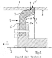
- FIG. 1 An article according to the preamble of claim 1 is in Fig. 1 shown in a partial sectional view showing an upper part of a pig according to the invention.
- the pig shown only with a front area, moves in direction F through a pipeline, of which a wall 1 is shown in sections.
- a cuff according to the invention for this pig designed as a cleaning or inspection pig has a longitudinal center axis 2 around which the cuff 3 is formed.
- the longitudinal center axis 2 points in the direction of a longitudinal center axis of the pipeline.
- the sleeve 3 has an inner fastening region 6 fastened to a pig body 4 and a contact region 7, shown in dash-dotted lines, directed towards the pipe wall, which presses against an inside 8 of the pipe wall 1.
- the contact area 7 would be the contact area 7 'further issued to the outside.
- the contact area 7 or 7 ' is part of an outer segment 9, which in the present case is connected to the inner fastening area 6 via a thin point 11.
- the cuff 3 is a conventional cup, as is known from the prior art.
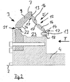
- a pig or a cuff 3 has an anchoring segment 12 which comprises a first end 13 which is arranged on the outer segment 9 and a second end 14 which is arranged on the side of the pig body 4 and thus towards the longitudinal center axis 2 ( Fig. 2 ).
- this second end 14 is arranged downstream of the first end 13 with respect to a direction of movement F.
- This arrangement results in an additional force component in the direction D 'towards the longitudinal center axis 2 in the event of an increase in differential pressure due to a situation in which the pig moves more slowly or even gets stuck in the pipeline, which counteracts a force component in direction D, if present .
- the pig can thus run more evenly through the pipeline, since it continues to travel even at lower differential pressures and thus the resulting differential speeds are lower in the event of overshooting.
- the anchoring segment 12 which, like the outer segment 9 and the fastening area, is arranged circumferentially around the longitudinal center axis 2, comprises a total of 3 joints 17 in the form of film hinges that delimit two thicker anchoring segment sections 16.
- the joints 17 are formed by thin spots.
- the guy segment 12 also has a fastening flange 18 which is inserted into a corresponding recess in the pig body 4 and is fixed in this via a fastening means 19.
- a fastening means 19 In the circumferential direction around the longitudinal center axis 2 there is a multiplicity of such fastening means, preferably designed as screws.
- a pressure equalization opening 21 leads into a channel 22 through which a cavity 23 is in pressure equalization with the area in front of the pig.
- the guy segment 12 is not arranged at the outermost end of the same, but is offset further inward so that, viewed in the longitudinal direction F, part of the cuff 3 is flowed directly against the medium, while a predominant part of the medium is no longer against an inner surface 24 of the inner fastening area or of the outer segment of the cuff 3 flows instead against the guy segment 12.
- a cup is also further developed according to the invention, with the anchoring segment here being an additional anchoring segment section 16, which is also thickened again and is connected to the rest of the anchoring segment 12 via articulations 17 forming film hinges.
- the embodiments of Figures 2 and 3 are provided with sleeves 3 which are made in one piece from polyurethane.
- the guy segment is provided with rigid sections 27 connected to one another via joints 26.
- This can be an embodiment according to FIG Fig. 3 act. However, it can actually be anchoring segment parts which are actually not manufactured in one piece with the rest of the cuff but consist of a different material and whose joints are designed to be movable to a limited extent according to the opening of the respective half-shells.
- the guy segment is formed by a membrane 30 which is flexible and which can buckle under the action of pressure.
- a roller 29 is provided on the outside, which causes additional rolling on an inner wall of the pipe.
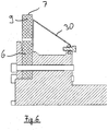
- a conventional disk can also be provided with an anchoring segment 12 in the form of a membrane 30, as shown in FIG Fig. 6 is shown.
- a pig according to the invention can be provided with a sleeve 3 which has an anchoring segment 12 which comprises thickened anchoring segment sections 16 which extend through Thin area 31 are separated from each other ( Fig. 7 ).
- a compression of the cuff 3 is possible in an improved manner, since the anchoring segment 12 is designed to be flexible due to the thin regions 31.
Landscapes
- Engineering & Computer Science (AREA)
- Mechanical Engineering (AREA)
- Physics & Mathematics (AREA)
- Fluid Mechanics (AREA)
- General Engineering & Computer Science (AREA)
- Chemical & Material Sciences (AREA)
- Combustion & Propulsion (AREA)
- Cleaning In General (AREA)
Description
- Die vorliegende Erfindung betrifft eine Manschette für einen Reinigungs- oder Inspektionsmolch, der in einer Rohrleitung und durch diese hindurch bewegbar ist, mit einem bezogen auf eine Längsmittelachse der Manschette inneren Befestigungsbereich zur Festlegung der Manschette an dem Reinigungs- oder Inspektionsmolch und mit einem Anlagebereich, der zur Anlage an einer Rohrwand vorgesehen ist und der Teil eines Außensegments ist, welches mit dem inneren Befestigungsbereich verbunden ist, wobei der innere Befestigungsbereich bezogen auf eine Bewegungsrichtung des Molches dem Anlagebereich vorzugsweise zumindest teilweise vorlaufend ist. Des Weiteren betrifft die Erfindung einen Molch zur Inspektion oder Reinigung von Pipelinerohren.
- Passiv betriebene Molche werden zum Inspizieren und Reinigen von Rohrleitungen, beispielsweise von Gas- oder Ölpipelines verwendet. Für den vom Medium ausgeübten Vortrieb sind die Molche mit Manschetten versehen, die in Richtung ihrer Längsmittelachse, die auch der Längsmittelachse der Pipeline entspricht, den freien Rohrleitungsquerschnitt möglichst gut abdecken. Das Medium drückt gegen die Manschetten und treibt den Molch hierdurch voran. Bekannt sind Manschetten, die in Richtung Ihrer flächigen Erstreckung im Wesentlichen plan ausgebildet sind. Diese scheibenförmigen Manschetten werden auch "Disks" genannt. Als "Cups" werden Manschetten bezeichnet, die zu den Rändern hin und bezüglich einer Vorzugs- und Vorwärtsbewegungsrichtung nach hinten gebogen oder abgeknickt sind. Insofern ist der innere Befestigungsbereich zumindest mit seiner in die Bewegungsrichtung nach vorne weisenden Vorderseite dem auf dem nach hinten gebogenen äußeren Außensegment befindlichen Anlagebereich vorlaufend. Der äußerste Randbereich dieser Manschetten kann sich sogar flächig zur Rohrinnenwand erstrecken. Beide Arten von Manschetten sind in der
DE 195 02 764 A1 gezeigt. Gerade bei diesen Cups wie aber auch bei den Disks gibt es bei einer Differenzdruckerhöhung aufgrund von beispielsweise zu stark verjüngten Rohrinnendurchmessern, in denen der Molch stark verlangsamt wird oder steckenbleiben kann, insbesondere bei gasdurchströmten Pipelines das Problem, das bei Differenzdruckerhöhung die Reibung der Manschette an der Rohrinnenwand stark zunimmt. Dies führt bei Überwindung der Reibungskraft zu einem sogenannten Vorwärtschießen des Molches mit stark erhöhter Geschwindigkeit, die außerhalb der für eine Reinigung oder Messung vorgegebenen Toleranzen liegt. Das Steckenbleiben und Vorwärtsschießen des Molches führt zu ungewünschten Druckschwankungen in der Rohrleitung bzw. Pipeline. - Aus der
US 2,328,093 ist ein Reinigungsmolch mit einer Manschette bekannt, die aus zwei gelenkig verbundenen Hälften besteht und die über zwei mit den jeweiligen Hälften verbundenen Abspannsegmente in Form von Gelenkverbindern abgestützt beziehungsweise zusammengeklappt wird. Ein Molch, der in einem durch Verformung oder Verschmutzung verengten Rohrquerschnitt festgefahren ist, kann mit zusammengeklappter Manschette über Kabel aus der Blockadestellung herausgezogen werden. Dabei wird das Zusammenklappen durch ein rückseitig am Molch angebrachtes Rückzugskabel getätigt. - Es ist Aufgabe der vorliegenden Erfindung, eine Manschette und einen Molch zur Verfügung zu stellen, mit denen eine Beruhigung des Laufverhaltens eines Molches in der Pipeline ermöglicht wird.
- Die Aufgabe wird gelöst durch einen Gegenstand nach Anspruch 1 sowie durch einen Gegenstand nach Anspruch 10. Weitere vorteilhafte Ausgestaltungen der Erfindung sind den auf Anspruch 1 rückbezogenen Unteransprüchen zu entnehmen.
- Es ist vorgesehen, dass die Manschette ein Abspannsegment umfasst, dessen erstes Ende an dem Außensegment angeordnet und dessen anderes, zweites Ende bezogen auf die Längsmittelachse weiter zu dieser hin und dem ersten Ende bezogen auf eine Bewegungsrichtung des Molches nachlaufend angeordnet ist. Hierdurch kann ein Teil der Manschette, der zu einer Umlenkung der Antriebskraft in Richtung von der Längsmittelachse weg in Richtung Rohrwand führen würde, durch das Abspannelement oder -segment abgedeckt werden. Das Abspannsegment ist hierbei so angeordnet, dass eine Differenzdruckerhöhung zu einer teilweisen Erhöhung des Drucks in Richtung der Längsmittelachse führt. Das Abspannelement zieht somit das Außensegment der Manschette nach innen, was dem verstärkten Druck in Richtung nach außen entgegenwirkt. Im Idealfall können sich die verstärkten Drücke in Richtung der Längsmittelachse und entgegengesetzt hierzu nach außen kompensieren beziehungsweise so eingestellt werden, dass bei typischerweise zu erwartenden Querschnittsänderungen in der Rohrleitung oder Pipeline die durch die Querschnittsänderung bewirkte Reibungserhöhung in Summe kompensiert wird. Der Druck nach außen ergibt sich -betrachtet in Richtung der Längsmittelachse- durch die nicht von dem Abspannsegment abgedeckten Manschettenbereiche, die bei Erhöhung des Differenzdruckes im Falle einer Fahrtverlangsamung oder einem Steckenbleiben des Molches verstärkt nach außen gedrückt werden und somit die Reibung der Manschette an der Rohrwand der Pipeline erhöhen. Erfindungsgemäß wird somit die mit Differenzdruck beaufschlagte Geometrie der Manschette zur Verringerung der Radialkraft auf die Rohrleitungswand variiert. Die nachlaufende Anordnung des nach innen liegenden, zweiten Endes führt zur Ausbildung einer Fläche, die unabhängig von der Form des Abspannelements bei Krafteinwirkung auf diese Fläche eine resultierende Kraft in Richtung der Längsmittelachse aufweist.
- Durch eine erfindungsgemäße Ausbildung der Manschette zeigt ein hiermit versehener Molch ein ruhigeres Laufverhalten. Der Verschleiß der Manschetten ist verringert und die Druckschwankungen in der Pipeline sind reduziert.
- Vorzugsweise ist das Abspannsegment an dem Außensegment in Richtung der Längsmittelachse beabstandet von dem Anlagebereich angeordnet, während das zweite Ende an dem Befestigungsbereich oder einem Molchteil festlegbar oder festgelegt ist. Die Anordnung des Abspannsegments ist dergestalt, dass das Abspannsegment auf einer nach hinten oder innen gewandten Seite und beabstandet von dem äußersten Umfang des Außensegments angeordnet ist. Ein Teil des Außensegments ist immer noch unmittelbar durch das Medium anströmbar während ein nach innen liegender, anströmbarer Teil der Manschette nun durch das Abspannelement gebildet wird. Eine Differenzdruckerhöhung auf das Abspannelement führt zu einer Kraft in Richtung der Längsmittelachse.
- Eine weitere vorteilhafte Ausbildung der Erfindung zeichnet sich dadurch aus, dass das Abspannsegment wenigstens teilweise einen Hohlraum zum Außensegment und/oder zum inneren Befestigungsbereich ausbildet. Zumindest ist der Hohlraum in der Befestigungssituation am Molch vorhanden. Die Manschette würde dann in Ihrer nicht montierten Form einen Hinterschneidung oder Ausnehmung aufweisen. Durch die Ausbildung mit einem Hohlraum ist das vorzugsweise flexible, biegsame oder abschnittsweise gelenkig ausgebildete Abspannelement unter Differenzdruckerhöhung besser beweglich.
- Für einen Druckausgleich kann die Manschette mit einer Druckausgleichsöffnung versehen werden, die bezüglich einer Bewegungsrichtung von vorne zu dem Hohlraum führt. Durch die Größe der Druckausgleichsöffnung lassen sich die Dämpfungseigenschaften der Manschette beeinflussen. So führt eine kleinere Öffnung zu einer langsameren Formveränderung der Manschette. Um einen Bypassstrom über den gesamten Molch ermöglichen zu können, kann auch das Abspannsegment mit Öffnungen versehen werden. Diese Öffnungen müssen allerdings in Summe über die gesamte Querschnittsfläche kleiner sein als die vordere Druckausgleichsöffnung(en), damit der überwiegende Druckanteil an dem Abspannsegment abfällt.
- Eine gezielte Form unter Druck und eine gewünschte Bewegbarkeit des Abspannsegments wird dann erreicht, wenn das Abspannsegment mit zumindest einem Gelenk zur Zwangsführung einzelner Abspannsegmentabschnitte versehen ist. Bevorzugt weist das Abspannsegment zwei, drei oder mehr Segmentabschnitte auf, die über Gelenke beispielsweise in Form von Filmscharnieren verbunden sind. Die Verwendung von Gelenken führt zur Ausbildung einer gewünschten Querschnittsform des Abspannsegments. Eine gezielte Formänderung kann durch unterschiedlich dicke Bereiche des Segments und eine hiermit einhergehende unterschiedliche Steifigkeit der jeweiligen Bereiche erreicht werden.
- Vorzugsweise ist ein zwischen zwei Gelenken befindlicher Abspannsegmentabschnitt gegenüber dem Gelenk verdickt ausgebildet ist, um eine ausreichende Stabilität aufzuweisen.
- Alternativ oder ergänzend zu durch Dünnstellen ausgebildeten Gelenken oder Gelenkbereichen kann das Abspannsegment aus unterschiedlichen Materialien gefertigt sein. So können beispielsweise ein weiches Kunststoffmaterial für die Gelenke und ein steifes Kunststoffmaterial für die übrigen Teile des Abspannsegments verwendet werden.
- Die Montage einer erfindungsgemäßen Manschette ist verbessert möglich, wenn das Abspannsegment an seinem zweiten Ende einen Befestigungsflansch insbesondere zur Einführung in einen komplementär ausgebildeten Bereiches des Molches aufweist. Beispielsweise kann es sich um ein Einsteckteil handeln, welches über Schrauben am Molch gesichert ist.
- Zur verbesserten Anpassung an unterschiedliche Rohrinnendurchmesser kann das Abspannsegment in Umfangsrichtung Dünnbereich aufweisen. Diese trennen Bereich des Abspannsegments, die stabiler und insbesondere dicker ausgebildet sind. Somit kann sich bei einer Verringerung oder Vergrößerung des freien Rohrleitungsdurchmessers und einem hiermit einhergehenden Stauchen oder Verbreitern der Manschette auch das Abspannelement besser stauchen oder verbreitern.
- Vorzugsweise ist die Manschette mit dem Abspannsegment einstückig und insbesondere aus Polyurethan hergestellt. Mit diesem Material können vergleichsweise komplexe Manschettenformen einfach hergestellt werden.
- Die vorbeschriebenen Vorteile kommen auch einem Molch zur Reinigung oder Inspektion von Pipeline-Rohren zu, der eine vor- oder nachbeschriebene Manschette aufweist.
- Weitere Vorteile und Einzelheiten der Erfindung lassen sich der nachfolgenden Figurenbeschreibung entnehmen. Schematisch dargestellt zeigt:
- Fig. 1
- eine teilweise Schnittansicht einer Vorrichtung nach dem Stand der Technik,
- Fig. 2
- eine teilweise Schnittansicht einer Vorrichtung nach der Erfindung,
- Fig. 3
- einen weiteren erfindungsgemäßen Gegenstand in einer teilweisen Schnittansicht,
- Fig. 4
- einen weiteren erfindungsgemäßen Gegenstand in einer teilweisen Schnittansicht,
- Fig. 5
- einen weiteren erfindungsgemäßen Gegenstand in einer teilweisen Schnittansicht,
- Fig. 6
- einen weiteren erfindungsgemäßen Gegenstand in einer teilweisen Schnittansicht,
- Fig. 7
- eine Teilansicht eines weiteren erfindungsgemäßen Gegenstands in einer perspektivischen Darstellung.
- Einzelne technische Merkmale der nachbeschriebenen Ausführungsbeispiele können auch in Kombination mit vorbeschriebenen Ausführungsbeispielen sowie den Merkmalen der unabhängigen Ansprüche und etwaiger weiterer Ansprüche zu erfindungsgemäßen Gegenständen kombiniert werden.
- Ein Gegenstand nach dem Oberbegriff des Anspruchs 1 ist in der
Fig. 1 in einer teilweisen Schnittansicht, die einen oberen Teil eines erfindungsgemäßen Molches darstellt, gezeigt. Der nur mit einem vorderen Bereich dargestellte Molch bewegt sich in Richtung F durch eine Rohrleitung, von der eine Wand 1 abschnittsweise dargestellt ist. Eine erfindungsgemäße Manschette für diesen als Reinigungs- oder Inspektionsmolch ausgebildeten Molch weist eine Längsmittelachse 2 auf, um die die Manschette 3 herum ausgebildet ist. Die Längsmittelachse 2 weist in Richtung einer Längsmittelachse der Rohrleitung. - Die Manschette 3 weist einen an einem Molchkörper 4 befestigten, inneren Befestigungsbereich 6 auf sowie einen strichpunktiert gezeichneten, zur Rohrwand hin gerichteten Anlagebereich 7, der gegen eine Innenseite 8 der Rohrwand 1 drückt. In der entspannten Form der Manschette wäre der Anlagebereich 7 als Anlagebereich 7' weiter nach außen ausgestellt. Der Anlagebereich 7 bzw. 7' ist Teil eines Außensegments 9, welches im vorliegenden Fall über eine Dünnstelle 11 mit dem inneren Befestigungsbereich 6 verbunden ist. Bei der Manschette 3 handelt es sich um eine(n) üblichen Cup, wie sie aus dem Stand der Technik bekannt ist.
- Bei einer Differenzdruckerhöhung aufgrund einer Verlangsamung der Bewegung des Molches ergibt sich eine zusätzliche Kraftkomponente in Richtung des Pfeils D, die zu einer Erhöhung der Reibung an der Rohrwand 1 führt.
- Ein Molch bzw. eine Manschette 3 weist ein Abspannsegment 12 auf, welches ein erstes Ende 13 umfasst, das an dem Außensegment 9 angeordnet ist, sowie ein zweites Ende 14, welches auf Seiten des Molchkörpers 4 und somit zur Längsmittelachse 2 hin angeordnet ist (
Fig. 2 ). Darüber hinaus ist dieses zweite Ende 14 bezüglich einer Bewegungsrichtung F dem ersten Ende 13 nachgeordnet. Durch diese Anordnung ergibt sich im Fall einer Differenzdruckerhöhung aufgrund einer Situation, in der der Molch langsamer fährt oder sogar in der Rohrleitung stecken bleibt, eine zusätzliche Kraftkomponente in Richtung D' hin zu der Längsmittelachse 2, die einer Kraftkomponente in Richtung D, sofern vorhanden entgegenwirkt. Der Molch kann somit gleichmäßiger durch die Rohrleitung laufen, da er bereits bei geringeren Differenzdrücken weiterfährt und somit die sich ergebenden Differenzgeschwindigkeiten im Falle eines Überschießens geringer ausfallen. - Das erfindungsgemäße Abspannsegment 12, welches genau wie das Außensegment 9 und der Befestigungsbereich umlaufend um die Längsmittelachse 2 angeordnet ist, umfasst insgesamt 3 Gelenke 17 in Form von Filmscharnieren, die zwei dickere Abspannsegmentabschnitte 16 begrenzen.
- Die Gelenke 17 sind durch Dünnstellen ausgebildet. Am Ende 14 weist das Abspannsegment 12 darüber hinaus einen Befestigungsflansch 18 auf, der in einer entsprechende Ausnehmung des Molchkörpers 4 steckt und in dieser über ein Befestigungsmittel 19 festgelegt ist. In Umfangsrichtung um die Längsmittelachse 2 herum ist eine Vielzahl solcher vorzugsweise als Schrauben ausgebildeter Befestigungsmittel vorhanden.
- Eine Druckausgleichsöffnung 21 führt in einen Kanal 22 hinein, über den ein Hohlraum 23 in Druckausgleich mit dem vor dem Molch befindlichen Bereich steht.
- Das Abspannsegment 12 ist bezüglich einer radialen Erstreckung der Manschette 3 nicht am äußersten Ende derselben angeordnet sondern weiter nach Innen versetzt, so dass in Längsrichtung F betrachtet ein Teil der Manschette 3 direkt von dem Medium angeströmt wird, während ein überwiegender Teil des Mediums nicht mehr gegen eine Innenoberfläche 24 des inneren Befestigungsbereichs oder des Außensegments der Manschette 3 strömt sondern gegen das Abspannsegment 12.
- Im Ausführungsbeispiel gemäß
Fig. 3 ist ebenfalls wieder eine Cup erfindungsgemäß weitergebildet, wobei hier das Abspannsegment einen zusätzlichen Abspannsegmentabschnitt 16 aufweist, der ebenfalls wieder verdickt ausgebildet und über Filmscharniere ausbildende Gelenke 17 mit dem Rest des Abspannsegments 12 verbunden ist. Die Ausführungsbeispiele derFiguren 2 und3 sind mit Manschetten 3 versehen, die einstückig aus Polyurethan gefertigt sind. - Im Ausführungsbeispiel der
Fig. 4 ist das Abspannsegment mit über Gelenke 26 miteinander verbundenen starren Abschnitten 27 versehen. Hierbei kann es sich um ein Ausführungsbeispiel gemäß derFig. 3 handeln. Es kann sich jedoch auch um tatsächlich nicht einstückig mit dem Rest der Manschette hergestellte sondern aus einem anderen Material bestehende Abspannsegmentteile handeln, deren Gelenke entsprechend der Öffnung der jeweiligen Halbschalen 28 begrenzt bewegbar ausgebildet sind. - Im Ausführungsbeispiel gemäß der
Fig. 5 ist das Abspannsegment durch eine Membran 30 ausgebildet, die biegsam ist und die sich unter einer Druckeinwirkung einbeulen kann. Außenseitig ist eine Rolle 29 vorgesehen, die ein zusätzliches Abrollen auf einer Rohrinnenwand bewirkt. - Eine herkömmliche Disk kann ebenfalls mit einem Abspannsegment 12 in Form einer Membran 30 versehen sein, wie dies in der
Fig. 6 dargestellt ist. - In einer Umfangsrichtung um die Längsmittelachse 2 herum kann ein erfindungsgemäßer Molch mit einer Manschette 3 versehen sein, die ein Abspannsegment 12 aufweist, welches verdickte Abspannsegmentabschnitte 16 umfasst, die durch Dünnbereich 31 voneinander getrennt sind (
Fig. 7 ). Ein Stauchen der Manschette 3 wird hierdurch verbessert möglich, da durch die Dünnbereiche 31 das Abspannsegment 12 flexibel ausgebildet ist.
Claims (10)
- Manschette für einen Reinigungs- oder Inspektionsmolch, der in einer Rohrleitung und durch diese hindurch bewegbar ist, mit einem bezogen auf eine Längsmittelachse (2) der Manschette (3) inneren Befestigungsbereich (6) zur Festlegung der Manschette (3) an dem Reinigungs- oder Inspektionsmolch und mit einem Anlagebereich (7), der zur Anlage an einer Rohrwand (1) vorgesehen ist und der Teil eines Außensegments (9) ist, welches mit dem inneren Befestigungsbereich (6) verbunden ist, wobei der innere Befestigungsbereich (6) bezogen auf eine Bewegungsrichtung (F) des Molches dem Anlagebereich (7, 7') vorzugsweise vorlaufend ist, wobei die Manschette (3) ein Abspannsegment (12) umfasst, dessen erstes Ende (13) an dem Außensegment (9) angeordnet und dessen anderes, zweites Ende (14) bezogen auf die Längsmittelachse (2) weiter zu dieser hin und dem ersten Ende (13) bezogen auf eine Bewegungsrichtung des Molches nachlaufend angeordnet ist, dadurch gekennzeichnet, dass das Abspannsegment (12) eine Fläche ausbildet, die unabhängig von der Form des Abspannsegments (12) bei Krafteinwirkung aufgrund einer Differenzdruckerhöhung auf diese Fläche eine resultierende Kraft in Richtung hin zur Längsmittelachse (2) aufweist, wobei das Abspannsegment (12) das Außensegment (9) der Manschette nach innen zieht.
- Manschette nach Anspruch 1, dadurch gekennzeichnet, dass das Abspannsegment (12) an dem Außensegment (9)in Richtung der Längsmittelachse (2) beabstandet von dem Anlagebereich (7) angeordnet ist und das zweite Ende (14) an dem Befestigungsbereich (6) oder einem Molchteil festlegbar oder festgelegt ist.
- Manschette nach Anspruch 1 oder 2, dadurch gekennzeichnet, dass das Abspannsegment (12) wenigstens teilweise einen Hohlraum (23) zum Außensegment (9) und/oder zum inneren Befestigungsbereich (6) ausbildet.
- Manschette nach Anspruch 3, dadurch gekennzeichnet, dass die Manschette (3) eine Druckausgleichsöffnung (21) aufweist, die bezüglich einer Bewegungsrichtung (F) von vorne zu dem Hohlraum (23) führt.
- Manschette nach einem der vorherigen Ansprüche, dadurch gekennzeichnet, dass das Abspannsegment (12) mit zumindest einem Gelenk (17) zur Zwangsführung einzelner Abspannsegmentabschnitte (16) ausgebildet ist.
- Manschette nach Anspruch 5, dadurch gekennzeichnet, dass ein zwischen zwei Gelenken (17) befindlicher Abspannsegmentabschnitt (16) gegenüber dem Gelenk (17) verdickt ausgebildet ist.
- Manschette nach einem der vorherigen Ansprüche, dadurch gekennzeichnet, dass das Abspannsegment (12) an seinem zweiten Ende (14) einen Befestigungsflansch (18) insbesondere zur Einführung in einen komplementär ausgebildeten Bereich aufweist.
- Manschette nach einem der vorherigen Ansprüche, dadurch gekennzeichnet, dass das Abspannsegment (12) in Umfangsrichtung zur verbesserten Anpassung an unterschiedliche Rohrinnendurchmesser Dünnbereiche (31) aufweist.
- Manschette nach einem der vorherigen Ansprüche, dadurch gekennzeichnet, dass die Manschette (3) mit dem Abspannsegment (12) einstückig und insbesondere aus Polyurethan hergestellt ist.
- Molch zur Reinigung oder Inspektion von Pipeline-Rohren, gekennzeichnet durch eine Manschette (3) nach einem der vorherigen Ansprüche .
Applications Claiming Priority (2)
| Application Number | Priority Date | Filing Date | Title |
|---|---|---|---|
| DE201310111019 DE102013111019A1 (de) | 2013-10-04 | 2013-10-04 | Manschette für einen Inspektions- oder Reinigungsmolch und Molch |
| PCT/EP2014/002616 WO2015049041A1 (de) | 2013-10-04 | 2014-09-26 | Manschette für einen inspektions- oder reinigungsmolch |
Publications (2)
| Publication Number | Publication Date |
|---|---|
| EP3052253A1 EP3052253A1 (de) | 2016-08-10 |
| EP3052253B1 true EP3052253B1 (de) | 2021-04-28 |
Family
ID=51844658
Family Applications (1)
| Application Number | Title | Priority Date | Filing Date |
|---|---|---|---|
| EP14792384.1A Active EP3052253B1 (de) | 2013-10-04 | 2014-09-26 | Manschette für einen inspektions- oder reinigungsmolch |
Country Status (6)
| Country | Link |
|---|---|
| US (1) | US10612714B2 (de) |
| EP (1) | EP3052253B1 (de) |
| CA (1) | CA2926263C (de) |
| DE (1) | DE102013111019A1 (de) |
| ES (1) | ES2882089T3 (de) |
| WO (1) | WO2015049041A1 (de) |
Families Citing this family (4)
| Publication number | Priority date | Publication date | Assignee | Title |
|---|---|---|---|---|
| US10399261B2 (en) | 2015-07-10 | 2019-09-03 | Resinnovation Gmbh | Method and device for producing a pipe lining |
| NO2751375T3 (de) * | 2015-07-10 | 2018-03-17 | ||
| US10458822B2 (en) * | 2016-07-11 | 2019-10-29 | Entegra LLP | Dynamic spacer for a smart pipeline inspection gauge |
| WO2019055546A1 (en) | 2017-09-13 | 2019-03-21 | Entegra LLP | SPEED CONTROL DEVICES FOR INTELLIGENT PIPELINE INSPECTION GAUGE |
Family Cites Families (7)
| Publication number | Priority date | Publication date | Assignee | Title |
|---|---|---|---|---|
| US2328093A (en) * | 1942-06-15 | 1943-08-31 | William D Osborn | Kite-type sewer washer |
| DE8908714U1 (de) * | 1989-06-27 | 1989-09-14 | I.S.T. Molchtechnik GmbH, 2000 Hamburg | Rohrleitungsmolch |
| DE19502764A1 (de) | 1995-01-30 | 1996-08-01 | Pipetronix Gmbh | Verfahren und Vorrichtung zum Prüfen von gasführenden Rohrleitungen |
| DE19746510C2 (de) * | 1997-10-22 | 2003-03-06 | Pii Pipetronix Gmbh | Vorrichtung zum Durchfahren von Rohrleitungen |
| DE20020990U1 (de) * | 2000-12-12 | 2001-04-05 | I.S.T. Industrie Service Technologie Beratungs- und Beteiligungsgesellschaft mbH, 22145 Hamburg | Rohrleitungsmolch |
| CA2530932C (en) * | 2005-12-20 | 2013-08-13 | Pii (Canada) Limited | Device for cleaning multidiameter pipelines |
| CN103987466B (zh) * | 2011-09-28 | 2016-10-19 | 伊恩·多伊格 | 单向清管器与管道组合 |
-
2013
- 2013-10-04 DE DE201310111019 patent/DE102013111019A1/de not_active Withdrawn
-
2014
- 2014-09-26 CA CA2926263A patent/CA2926263C/en active Active
- 2014-09-26 ES ES14792384T patent/ES2882089T3/es active Active
- 2014-09-26 WO PCT/EP2014/002616 patent/WO2015049041A1/de not_active Ceased
- 2014-09-26 EP EP14792384.1A patent/EP3052253B1/de active Active
- 2014-09-26 US US15/025,016 patent/US10612714B2/en active Active
Non-Patent Citations (1)
| Title |
|---|
| None * |
Also Published As
| Publication number | Publication date |
|---|---|
| CA2926263C (en) | 2022-02-15 |
| DE102013111019A1 (de) | 2015-04-09 |
| EP3052253A1 (de) | 2016-08-10 |
| US20160238184A1 (en) | 2016-08-18 |
| WO2015049041A1 (de) | 2015-04-09 |
| CA2926263A1 (en) | 2015-04-09 |
| US10612714B2 (en) | 2020-04-07 |
| ES2882089T3 (es) | 2021-12-01 |
Similar Documents
| Publication | Publication Date | Title |
|---|---|---|
| DE3873033T2 (de) | Bewegliche verbindung fuer rohrfoermige leitungen. | |
| DE69631031T2 (de) | Schnellverbindung mit befestigungsring | |
| EP2724068B1 (de) | Schlauchnippel und schlauchanordnung | |
| DE69002047T2 (de) | Rohrkupplung. | |
| WO2013189740A2 (de) | Klemmverbindung für rohre | |
| DE7817369U1 (de) | Schnellkupplung fuer flexible rohre | |
| EP2765344B1 (de) | Kupplungseinheit | |
| EP2090385A2 (de) | Vorrichtung zum Aufweiten von Rohren | |
| DE102007061906A1 (de) | Rohrverbindungseinheit und Verfahren zu deren Herstellung | |
| DE69409013T2 (de) | Verbesserte Schale zum Gebrauch in einer Rohrleitung | |
| DE112014002401T5 (de) | Verriegelungsmechanismus für Motorhauben-Anhebeeinrichtungen für Fußgänger | |
| WO2015049041A1 (de) | Manschette für einen inspektions- oder reinigungsmolch | |
| DE19811917A1 (de) | Kupplungsmechanismus für eine Zahnstange und deren Antriebsritzel | |
| EP3940281B1 (de) | Rohrmuffe | |
| DE102007045023A1 (de) | Steckverbindungsanordnung für Fluidleitungen | |
| DE102018133503A1 (de) | Spülwerkzeug für ein Handstück eines chirurgischen Instruments | |
| EP2522438B1 (de) | Verschluss- und Ausdrückkolben für Kartuschen für plastische Massen und Verfahren zum Einsetzen eines solchen Kolbens in eine Kartusche | |
| EP1384923B1 (de) | Dichtring zur Abdichtung eines Längenausgleichs einer Gelenkwelle | |
| DE102011105075B4 (de) | Schlauchnippel und Schlauchanordnung | |
| EP1099804A1 (de) | Vakuumtoilette | |
| DE2630716A1 (de) | Kugellager-ausruecker, insbesondere fuer kraftfahrzeugkupplungen | |
| DE812748C (de) | Elastische Lager- und Gelenkvorrichtung | |
| EP2366932A1 (de) | Steckmuffe und Verbindung zwischen einer Steckmuffe und einem Rohr | |
| DE3111726C1 (de) | Dichtungsring | |
| DE2630699A1 (de) | Kugellager-ausruecker, insbesondere fuer kraftfahrzeugkupplungen |
Legal Events
| Date | Code | Title | Description |
|---|---|---|---|
| PUAI | Public reference made under article 153(3) epc to a published international application that has entered the european phase |
Free format text: ORIGINAL CODE: 0009012 |
|
| 17P | Request for examination filed |
Effective date: 20160413 |
|
| AK | Designated contracting states |
Kind code of ref document: A1 Designated state(s): AL AT BE BG CH CY CZ DE DK EE ES FI FR GB GR HR HU IE IS IT LI LT LU LV MC MK MT NL NO PL PT RO RS SE SI SK SM TR |
|
| AX | Request for extension of the european patent |
Extension state: BA ME |
|
| DAX | Request for extension of the european patent (deleted) | ||
| STAA | Information on the status of an ep patent application or granted ep patent |
Free format text: STATUS: EXAMINATION IS IN PROGRESS |
|
| RIC1 | Information provided on ipc code assigned before grant |
Ipc: F16L 101/30 20060101ALI20181129BHEP Ipc: F16L 101/12 20060101ALI20181129BHEP Ipc: F16L 55/40 20060101ALI20181129BHEP Ipc: F16L 55/38 20060101ALI20181129BHEP Ipc: F16L 55/28 20060101ALI20181129BHEP Ipc: B08B 9/055 20060101AFI20181129BHEP |
|
| 17Q | First examination report despatched |
Effective date: 20181217 |
|
| GRAP | Despatch of communication of intention to grant a patent |
Free format text: ORIGINAL CODE: EPIDOSNIGR1 |
|
| STAA | Information on the status of an ep patent application or granted ep patent |
Free format text: STATUS: GRANT OF PATENT IS INTENDED |
|
| INTG | Intention to grant announced |
Effective date: 20201127 |
|
| GRAS | Grant fee paid |
Free format text: ORIGINAL CODE: EPIDOSNIGR3 |
|
| GRAA | (expected) grant |
Free format text: ORIGINAL CODE: 0009210 |
|
| STAA | Information on the status of an ep patent application or granted ep patent |
Free format text: STATUS: THE PATENT HAS BEEN GRANTED |
|
| AK | Designated contracting states |
Kind code of ref document: B1 Designated state(s): AL AT BE BG CH CY CZ DE DK EE ES FI FR GB GR HR HU IE IS IT LI LT LU LV MC MK MT NL NO PL PT RO RS SE SI SK SM TR |
|
| REG | Reference to a national code |
Ref country code: GB Ref legal event code: FG4D Free format text: NOT ENGLISH |
|
| REG | Reference to a national code |
Ref country code: CH Ref legal event code: EP |
|
| REG | Reference to a national code |
Ref country code: AT Ref legal event code: REF Ref document number: 1386524 Country of ref document: AT Kind code of ref document: T Effective date: 20210515 |
|
| REG | Reference to a national code |
Ref country code: DE Ref legal event code: R096 Ref document number: 502014015529 Country of ref document: DE |
|
| REG | Reference to a national code |
Ref country code: IE Ref legal event code: FG4D Free format text: LANGUAGE OF EP DOCUMENT: GERMAN |
|
| REG | Reference to a national code |
Ref country code: NL Ref legal event code: FP |
|
| REG | Reference to a national code |
Ref country code: LT Ref legal event code: MG9D |
|
| REG | Reference to a national code |
Ref country code: NO Ref legal event code: T2 Effective date: 20210428 |
|
| PG25 | Lapsed in a contracting state [announced via postgrant information from national office to epo] |
Ref country code: LT Free format text: LAPSE BECAUSE OF FAILURE TO SUBMIT A TRANSLATION OF THE DESCRIPTION OR TO PAY THE FEE WITHIN THE PRESCRIBED TIME-LIMIT Effective date: 20210428 Ref country code: FI Free format text: LAPSE BECAUSE OF FAILURE TO SUBMIT A TRANSLATION OF THE DESCRIPTION OR TO PAY THE FEE WITHIN THE PRESCRIBED TIME-LIMIT Effective date: 20210428 Ref country code: BG Free format text: LAPSE BECAUSE OF FAILURE TO SUBMIT A TRANSLATION OF THE DESCRIPTION OR TO PAY THE FEE WITHIN THE PRESCRIBED TIME-LIMIT Effective date: 20210728 Ref country code: HR Free format text: LAPSE BECAUSE OF FAILURE TO SUBMIT A TRANSLATION OF THE DESCRIPTION OR TO PAY THE FEE WITHIN THE PRESCRIBED TIME-LIMIT Effective date: 20210428 |
|
| PGFP | Annual fee paid to national office [announced via postgrant information from national office to epo] |
Ref country code: NL Payment date: 20210921 Year of fee payment: 8 Ref country code: IT Payment date: 20210930 Year of fee payment: 8 |
|
| PG25 | Lapsed in a contracting state [announced via postgrant information from national office to epo] |
Ref country code: GR Free format text: LAPSE BECAUSE OF FAILURE TO SUBMIT A TRANSLATION OF THE DESCRIPTION OR TO PAY THE FEE WITHIN THE PRESCRIBED TIME-LIMIT Effective date: 20210729 Ref country code: LV Free format text: LAPSE BECAUSE OF FAILURE TO SUBMIT A TRANSLATION OF THE DESCRIPTION OR TO PAY THE FEE WITHIN THE PRESCRIBED TIME-LIMIT Effective date: 20210428 Ref country code: IS Free format text: LAPSE BECAUSE OF FAILURE TO SUBMIT A TRANSLATION OF THE DESCRIPTION OR TO PAY THE FEE WITHIN THE PRESCRIBED TIME-LIMIT Effective date: 20210828 Ref country code: PL Free format text: LAPSE BECAUSE OF FAILURE TO SUBMIT A TRANSLATION OF THE DESCRIPTION OR TO PAY THE FEE WITHIN THE PRESCRIBED TIME-LIMIT Effective date: 20210428 Ref country code: PT Free format text: LAPSE BECAUSE OF FAILURE TO SUBMIT A TRANSLATION OF THE DESCRIPTION OR TO PAY THE FEE WITHIN THE PRESCRIBED TIME-LIMIT Effective date: 20210830 Ref country code: RS Free format text: LAPSE BECAUSE OF FAILURE TO SUBMIT A TRANSLATION OF THE DESCRIPTION OR TO PAY THE FEE WITHIN THE PRESCRIBED TIME-LIMIT Effective date: 20210428 Ref country code: SE Free format text: LAPSE BECAUSE OF FAILURE TO SUBMIT A TRANSLATION OF THE DESCRIPTION OR TO PAY THE FEE WITHIN THE PRESCRIBED TIME-LIMIT Effective date: 20210428 |
|
| REG | Reference to a national code |
Ref country code: ES Ref legal event code: FG2A Ref document number: 2882089 Country of ref document: ES Kind code of ref document: T3 Effective date: 20211201 |
|
| PG25 | Lapsed in a contracting state [announced via postgrant information from national office to epo] |
Ref country code: SM Free format text: LAPSE BECAUSE OF FAILURE TO SUBMIT A TRANSLATION OF THE DESCRIPTION OR TO PAY THE FEE WITHIN THE PRESCRIBED TIME-LIMIT Effective date: 20210428 Ref country code: SK Free format text: LAPSE BECAUSE OF FAILURE TO SUBMIT A TRANSLATION OF THE DESCRIPTION OR TO PAY THE FEE WITHIN THE PRESCRIBED TIME-LIMIT Effective date: 20210428 Ref country code: CZ Free format text: LAPSE BECAUSE OF FAILURE TO SUBMIT A TRANSLATION OF THE DESCRIPTION OR TO PAY THE FEE WITHIN THE PRESCRIBED TIME-LIMIT Effective date: 20210428 Ref country code: DK Free format text: LAPSE BECAUSE OF FAILURE TO SUBMIT A TRANSLATION OF THE DESCRIPTION OR TO PAY THE FEE WITHIN THE PRESCRIBED TIME-LIMIT Effective date: 20210428 Ref country code: EE Free format text: LAPSE BECAUSE OF FAILURE TO SUBMIT A TRANSLATION OF THE DESCRIPTION OR TO PAY THE FEE WITHIN THE PRESCRIBED TIME-LIMIT Effective date: 20210428 Ref country code: RO Free format text: LAPSE BECAUSE OF FAILURE TO SUBMIT A TRANSLATION OF THE DESCRIPTION OR TO PAY THE FEE WITHIN THE PRESCRIBED TIME-LIMIT Effective date: 20210428 |
|
| PGFP | Annual fee paid to national office [announced via postgrant information from national office to epo] |
Ref country code: ES Payment date: 20211019 Year of fee payment: 8 |
|
| REG | Reference to a national code |
Ref country code: DE Ref legal event code: R097 Ref document number: 502014015529 Country of ref document: DE |
|
| PLBE | No opposition filed within time limit |
Free format text: ORIGINAL CODE: 0009261 |
|
| STAA | Information on the status of an ep patent application or granted ep patent |
Free format text: STATUS: NO OPPOSITION FILED WITHIN TIME LIMIT |
|
| 26N | No opposition filed |
Effective date: 20220131 |
|
| REG | Reference to a national code |
Ref country code: CH Ref legal event code: PL |
|
| REG | Reference to a national code |
Ref country code: BE Ref legal event code: MM Effective date: 20210930 |
|
| PG25 | Lapsed in a contracting state [announced via postgrant information from national office to epo] |
Ref country code: IS Free format text: LAPSE BECAUSE OF FAILURE TO SUBMIT A TRANSLATION OF THE DESCRIPTION OR TO PAY THE FEE WITHIN THE PRESCRIBED TIME-LIMIT Effective date: 20210828 Ref country code: MC Free format text: LAPSE BECAUSE OF FAILURE TO SUBMIT A TRANSLATION OF THE DESCRIPTION OR TO PAY THE FEE WITHIN THE PRESCRIBED TIME-LIMIT Effective date: 20210428 Ref country code: AL Free format text: LAPSE BECAUSE OF FAILURE TO SUBMIT A TRANSLATION OF THE DESCRIPTION OR TO PAY THE FEE WITHIN THE PRESCRIBED TIME-LIMIT Effective date: 20210428 |
|
| PG25 | Lapsed in a contracting state [announced via postgrant information from national office to epo] |
Ref country code: LU Free format text: LAPSE BECAUSE OF NON-PAYMENT OF DUE FEES Effective date: 20210926 Ref country code: IE Free format text: LAPSE BECAUSE OF NON-PAYMENT OF DUE FEES Effective date: 20210926 Ref country code: BE Free format text: LAPSE BECAUSE OF NON-PAYMENT OF DUE FEES Effective date: 20210930 |
|
| PG25 | Lapsed in a contracting state [announced via postgrant information from national office to epo] |
Ref country code: LI Free format text: LAPSE BECAUSE OF NON-PAYMENT OF DUE FEES Effective date: 20210930 Ref country code: CH Free format text: LAPSE BECAUSE OF NON-PAYMENT OF DUE FEES Effective date: 20210930 |
|
| REG | Reference to a national code |
Ref country code: AT Ref legal event code: MM01 Ref document number: 1386524 Country of ref document: AT Kind code of ref document: T Effective date: 20210926 |
|
| PG25 | Lapsed in a contracting state [announced via postgrant information from national office to epo] |
Ref country code: AT Free format text: LAPSE BECAUSE OF NON-PAYMENT OF DUE FEES Effective date: 20210926 |
|
| REG | Reference to a national code |
Ref country code: NL Ref legal event code: MM Effective date: 20221001 |
|
| PG25 | Lapsed in a contracting state [announced via postgrant information from national office to epo] |
Ref country code: HU Free format text: LAPSE BECAUSE OF FAILURE TO SUBMIT A TRANSLATION OF THE DESCRIPTION OR TO PAY THE FEE WITHIN THE PRESCRIBED TIME-LIMIT; INVALID AB INITIO Effective date: 20140926 |
|
| PG25 | Lapsed in a contracting state [announced via postgrant information from national office to epo] |
Ref country code: NL Free format text: LAPSE BECAUSE OF NON-PAYMENT OF DUE FEES Effective date: 20221001 Ref country code: CY Free format text: LAPSE BECAUSE OF FAILURE TO SUBMIT A TRANSLATION OF THE DESCRIPTION OR TO PAY THE FEE WITHIN THE PRESCRIBED TIME-LIMIT Effective date: 20210428 |
|
| REG | Reference to a national code |
Ref country code: DE Ref legal event code: R081 Ref document number: 502014015529 Country of ref document: DE Owner name: ROSEN IP AG, CH Free format text: FORMER OWNER: ROSEN SWISS AG, STANS, CH |
|
| PG25 | Lapsed in a contracting state [announced via postgrant information from national office to epo] |
Ref country code: IT Free format text: LAPSE BECAUSE OF NON-PAYMENT OF DUE FEES Effective date: 20220926 |
|
| REG | Reference to a national code |
Ref country code: ES Ref legal event code: FD2A Effective date: 20231103 |
|
| REG | Reference to a national code |
Ref country code: NO Ref legal event code: CHAD Owner name: ROSEN IP AG, CH |
|
| REG | Reference to a national code |
Ref country code: GB Ref legal event code: 732E Free format text: REGISTERED BETWEEN 20231207 AND 20231213 |
|
| PG25 | Lapsed in a contracting state [announced via postgrant information from national office to epo] |
Ref country code: ES Free format text: LAPSE BECAUSE OF NON-PAYMENT OF DUE FEES Effective date: 20220927 |
|
| PG25 | Lapsed in a contracting state [announced via postgrant information from national office to epo] |
Ref country code: ES Free format text: LAPSE BECAUSE OF NON-PAYMENT OF DUE FEES Effective date: 20220927 |
|
| PG25 | Lapsed in a contracting state [announced via postgrant information from national office to epo] |
Ref country code: MK Free format text: LAPSE BECAUSE OF FAILURE TO SUBMIT A TRANSLATION OF THE DESCRIPTION OR TO PAY THE FEE WITHIN THE PRESCRIBED TIME-LIMIT Effective date: 20210428 |
|
| PG25 | Lapsed in a contracting state [announced via postgrant information from national office to epo] |
Ref country code: MT Free format text: LAPSE BECAUSE OF FAILURE TO SUBMIT A TRANSLATION OF THE DESCRIPTION OR TO PAY THE FEE WITHIN THE PRESCRIBED TIME-LIMIT Effective date: 20210428 |
|
| PGFP | Annual fee paid to national office [announced via postgrant information from national office to epo] |
Ref country code: DE Payment date: 20250919 Year of fee payment: 12 |
|
| PGFP | Annual fee paid to national office [announced via postgrant information from national office to epo] |
Ref country code: NO Payment date: 20250919 Year of fee payment: 12 |
|
| PGFP | Annual fee paid to national office [announced via postgrant information from national office to epo] |
Ref country code: GB Payment date: 20250923 Year of fee payment: 12 |
|
| PGFP | Annual fee paid to national office [announced via postgrant information from national office to epo] |
Ref country code: FR Payment date: 20250926 Year of fee payment: 12 |
|
| PG25 | Lapsed in a contracting state [announced via postgrant information from national office to epo] |
Ref country code: TR Free format text: LAPSE BECAUSE OF FAILURE TO SUBMIT A TRANSLATION OF THE DESCRIPTION OR TO PAY THE FEE WITHIN THE PRESCRIBED TIME-LIMIT Effective date: 20210428 |