EP3051677B1 - Power control system and method for controlling input power limit of dc-dc voltage converter - Google Patents
Power control system and method for controlling input power limit of dc-dc voltage converter Download PDFInfo
- Publication number
- EP3051677B1 EP3051677B1 EP15836406.7A EP15836406A EP3051677B1 EP 3051677 B1 EP3051677 B1 EP 3051677B1 EP 15836406 A EP15836406 A EP 15836406A EP 3051677 B1 EP3051677 B1 EP 3051677B1
- Authority
- EP
- European Patent Office
- Prior art keywords
- voltage
- power
- battery pack
- amount
- signal
- Prior art date
- Legal status (The legal status is an assumption and is not a legal conclusion. Google has not performed a legal analysis and makes no representation as to the accuracy of the status listed.)
- Active
Links
- 238000000034 method Methods 0.000 title claims description 36
- 230000007423 decrease Effects 0.000 claims description 4
- 230000003247 decreasing effect Effects 0.000 claims description 3
- 241001125929 Trisopterus luscus Species 0.000 claims 1
- HBBGRARXTFLTSG-UHFFFAOYSA-N Lithium ion Chemical compound [Li+] HBBGRARXTFLTSG-UHFFFAOYSA-N 0.000 description 2
- 239000002253 acid Substances 0.000 description 2
- 230000008901 benefit Effects 0.000 description 2
- OJIJEKBXJYRIBZ-UHFFFAOYSA-N cadmium nickel Chemical compound [Ni].[Cd] OJIJEKBXJYRIBZ-UHFFFAOYSA-N 0.000 description 2
- 230000000694 effects Effects 0.000 description 2
- 229910001416 lithium ion Inorganic materials 0.000 description 2
- 229910052987 metal hydride Inorganic materials 0.000 description 2
- 230000004075 alteration Effects 0.000 description 1
- 230000006870 function Effects 0.000 description 1
- 230000004048 modification Effects 0.000 description 1
- 238000012986 modification Methods 0.000 description 1
- 230000004044 response Effects 0.000 description 1
- 238000006467 substitution reaction Methods 0.000 description 1
Images

Classifications
-
- H—ELECTRICITY
- H02—GENERATION; CONVERSION OR DISTRIBUTION OF ELECTRIC POWER
- H02J—CIRCUIT ARRANGEMENTS OR SYSTEMS FOR SUPPLYING OR DISTRIBUTING ELECTRIC POWER; SYSTEMS FOR STORING ELECTRIC ENERGY
- H02J7/00—Circuit arrangements for charging or depolarising batteries or for supplying loads from batteries
- H02J7/34—Parallel operation in networks using both storage and other dc sources, e.g. providing buffering
- H02J7/345—Parallel operation in networks using both storage and other dc sources, e.g. providing buffering using capacitors as storage or buffering devices
-
- B—PERFORMING OPERATIONS; TRANSPORTING
- B60—VEHICLES IN GENERAL
- B60L—PROPULSION OF ELECTRICALLY-PROPELLED VEHICLES; SUPPLYING ELECTRIC POWER FOR AUXILIARY EQUIPMENT OF ELECTRICALLY-PROPELLED VEHICLES; ELECTRODYNAMIC BRAKE SYSTEMS FOR VEHICLES IN GENERAL; MAGNETIC SUSPENSION OR LEVITATION FOR VEHICLES; MONITORING OPERATING VARIABLES OF ELECTRICALLY-PROPELLED VEHICLES; ELECTRIC SAFETY DEVICES FOR ELECTRICALLY-PROPELLED VEHICLES
- B60L58/00—Methods or circuit arrangements for monitoring or controlling batteries or fuel cells, specially adapted for electric vehicles
- B60L58/10—Methods or circuit arrangements for monitoring or controlling batteries or fuel cells, specially adapted for electric vehicles for monitoring or controlling batteries
- B60L58/18—Methods or circuit arrangements for monitoring or controlling batteries or fuel cells, specially adapted for electric vehicles for monitoring or controlling batteries of two or more battery modules
- B60L58/20—Methods or circuit arrangements for monitoring or controlling batteries or fuel cells, specially adapted for electric vehicles for monitoring or controlling batteries of two or more battery modules having different nominal voltages
-
- B—PERFORMING OPERATIONS; TRANSPORTING
- B60—VEHICLES IN GENERAL
- B60L—PROPULSION OF ELECTRICALLY-PROPELLED VEHICLES; SUPPLYING ELECTRIC POWER FOR AUXILIARY EQUIPMENT OF ELECTRICALLY-PROPELLED VEHICLES; ELECTRODYNAMIC BRAKE SYSTEMS FOR VEHICLES IN GENERAL; MAGNETIC SUSPENSION OR LEVITATION FOR VEHICLES; MONITORING OPERATING VARIABLES OF ELECTRICALLY-PROPELLED VEHICLES; ELECTRIC SAFETY DEVICES FOR ELECTRICALLY-PROPELLED VEHICLES
- B60L2210/00—Converter types
- B60L2210/10—DC to DC converters
- B60L2210/12—Buck converters
-
- B—PERFORMING OPERATIONS; TRANSPORTING
- B60—VEHICLES IN GENERAL
- B60L—PROPULSION OF ELECTRICALLY-PROPELLED VEHICLES; SUPPLYING ELECTRIC POWER FOR AUXILIARY EQUIPMENT OF ELECTRICALLY-PROPELLED VEHICLES; ELECTRODYNAMIC BRAKE SYSTEMS FOR VEHICLES IN GENERAL; MAGNETIC SUSPENSION OR LEVITATION FOR VEHICLES; MONITORING OPERATING VARIABLES OF ELECTRICALLY-PROPELLED VEHICLES; ELECTRIC SAFETY DEVICES FOR ELECTRICALLY-PROPELLED VEHICLES
- B60L2210/00—Converter types
- B60L2210/40—DC to AC converters
- B60L2210/42—Voltage source inverters
-
- B—PERFORMING OPERATIONS; TRANSPORTING
- B60—VEHICLES IN GENERAL
- B60L—PROPULSION OF ELECTRICALLY-PROPELLED VEHICLES; SUPPLYING ELECTRIC POWER FOR AUXILIARY EQUIPMENT OF ELECTRICALLY-PROPELLED VEHICLES; ELECTRODYNAMIC BRAKE SYSTEMS FOR VEHICLES IN GENERAL; MAGNETIC SUSPENSION OR LEVITATION FOR VEHICLES; MONITORING OPERATING VARIABLES OF ELECTRICALLY-PROPELLED VEHICLES; ELECTRIC SAFETY DEVICES FOR ELECTRICALLY-PROPELLED VEHICLES
- B60L2240/00—Control parameters of input or output; Target parameters
- B60L2240/40—Drive Train control parameters
- B60L2240/54—Drive Train control parameters related to batteries
- B60L2240/545—Temperature
-
- B—PERFORMING OPERATIONS; TRANSPORTING
- B60—VEHICLES IN GENERAL
- B60L—PROPULSION OF ELECTRICALLY-PROPELLED VEHICLES; SUPPLYING ELECTRIC POWER FOR AUXILIARY EQUIPMENT OF ELECTRICALLY-PROPELLED VEHICLES; ELECTRODYNAMIC BRAKE SYSTEMS FOR VEHICLES IN GENERAL; MAGNETIC SUSPENSION OR LEVITATION FOR VEHICLES; MONITORING OPERATING VARIABLES OF ELECTRICALLY-PROPELLED VEHICLES; ELECTRIC SAFETY DEVICES FOR ELECTRICALLY-PROPELLED VEHICLES
- B60L2240/00—Control parameters of input or output; Target parameters
- B60L2240/40—Drive Train control parameters
- B60L2240/54—Drive Train control parameters related to batteries
- B60L2240/547—Voltage
-
- H—ELECTRICITY
- H02—GENERATION; CONVERSION OR DISTRIBUTION OF ELECTRIC POWER
- H02J—CIRCUIT ARRANGEMENTS OR SYSTEMS FOR SUPPLYING OR DISTRIBUTING ELECTRIC POWER; SYSTEMS FOR STORING ELECTRIC ENERGY
- H02J2207/00—Indexing scheme relating to details of circuit arrangements for charging or depolarising batteries or for supplying loads from batteries
- H02J2207/20—Charging or discharging characterised by the power electronics converter
-
- H—ELECTRICITY
- H02—GENERATION; CONVERSION OR DISTRIBUTION OF ELECTRIC POWER
- H02J—CIRCUIT ARRANGEMENTS OR SYSTEMS FOR SUPPLYING OR DISTRIBUTING ELECTRIC POWER; SYSTEMS FOR STORING ELECTRIC ENERGY
- H02J7/00—Circuit arrangements for charging or depolarising batteries or for supplying loads from batteries
- H02J7/0029—Circuit arrangements for charging or depolarising batteries or for supplying loads from batteries with safety or protection devices or circuits
- H02J7/00306—Overdischarge protection
-
- Y—GENERAL TAGGING OF NEW TECHNOLOGICAL DEVELOPMENTS; GENERAL TAGGING OF CROSS-SECTIONAL TECHNOLOGIES SPANNING OVER SEVERAL SECTIONS OF THE IPC; TECHNICAL SUBJECTS COVERED BY FORMER USPC CROSS-REFERENCE ART COLLECTIONS [XRACs] AND DIGESTS
- Y02—TECHNOLOGIES OR APPLICATIONS FOR MITIGATION OR ADAPTATION AGAINST CLIMATE CHANGE
- Y02T—CLIMATE CHANGE MITIGATION TECHNOLOGIES RELATED TO TRANSPORTATION
- Y02T10/00—Road transport of goods or passengers
- Y02T10/60—Other road transportation technologies with climate change mitigation effect
- Y02T10/70—Energy storage systems for electromobility, e.g. batteries
-
- Y—GENERAL TAGGING OF NEW TECHNOLOGICAL DEVELOPMENTS; GENERAL TAGGING OF CROSS-SECTIONAL TECHNOLOGIES SPANNING OVER SEVERAL SECTIONS OF THE IPC; TECHNICAL SUBJECTS COVERED BY FORMER USPC CROSS-REFERENCE ART COLLECTIONS [XRACs] AND DIGESTS
- Y02—TECHNOLOGIES OR APPLICATIONS FOR MITIGATION OR ADAPTATION AGAINST CLIMATE CHANGE
- Y02T—CLIMATE CHANGE MITIGATION TECHNOLOGIES RELATED TO TRANSPORTATION
- Y02T10/00—Road transport of goods or passengers
- Y02T10/60—Other road transportation technologies with climate change mitigation effect
- Y02T10/72—Electric energy management in electromobility
Definitions
- the present disclosure relates to a technique for adjusting an input power limit of a DC-DC voltage converter installed between batteries with different output voltages.
- a vehicle including an electric motor such as a hybrid vehicle, includes a large-capacity battery pack for supplying a high-level voltage to the electric motor, and a small-capacity battery for supplying a low-level voltage to electronic components loaded in the vehicle as described in EP 2823987 A1 for instance.
- a large-capacity battery pack for supplying a high-level voltage to the electric motor
- a small-capacity battery for supplying a low-level voltage to electronic components loaded in the vehicle as described in EP 2823987 A1 for instance.
- a power system having a DC-DC voltage converter installed between the large-capacity battery pack and the small-capacity battery.
- the DC-DC voltage converter drops a voltage of the battery pack and applies the voltage to the battery to charge the battery.
- a main purpose of the battery pack is to stably supply power to the electric motor. If the DC-DC voltage converter excessively consumes the power of the battery pack, power may not be stably supplied to the electric motor. In addition, if the power of the battery pack is excessively consumed by the DC-DC voltage converter in a state where a state of charge (SOC) of the battery pack is low, the battery pack may be over-discharged and thus irreversibly damaged.
- SOC state of charge
- the inventor herein has recognized a need for an improved system and a method for adjusting an input power limit of a DC-DC voltage converter.
- the present disclosure is designed against the background art, and therefore the present disclosure is directed to providing a power control system and method, which may prevent a battery pack from being damaged due to excessive power drawn from a DC-DC voltage converter and improve stability for power supply to an electric motor.
- a power control system for adjusting an input power limit of a DC-DC voltage converter electrically coupled to a positive electrode of a battery utilized to provide power to auxiliary vehicle devices in accordance with an exemplary embodiment includes a battery pack having a positive electrode and a negative electrode.
- the battery pack is adapted to generate a first voltage level between the positive electrode and the negative electrode that is received by the DC-DC voltage converter and a DC-AC inverter electrically coupled to a vehicle motor system.
- the power control system further includes a first voltage sensor adapted to generate a first voltage signal indicative of the first voltage level between the positive electrode and the negative electrode of the battery pack.
- the power control system further includes a first current sensor adapted to generate a first current signal indicative of a total current level flowing from the battery pack.
- the power control system further includes a second current sensor adapted to generate a second current signal indicative of a current level flowing from the battery pack to the DC-DC voltage converter.
- the power control system further includes a temperature sensor adapted to generate a temperature signal indicative of a temperature of the battery pack.
- the power control system further includes a microprocessor operably coupled to the first voltage sensor, the first current sensor, the second current sensor, and the temperature sensor. The microprocessor is programmed to determine an amount of output power being output by the battery pack based on the first voltage signal and the first current signal.
- the microprocessor is further programmed to determine an amount of available power in the battery pack based on the first current signal and the temperature signal.
- the microprocessor is further programmed to determine an amount of input power being input to the DC-DC voltage converter from the battery pack based on the second current signal and the first voltage signal.
- the microprocessor is further programmed to determine an amount of power being provided to the DC-AC inverter based on the amount of output power being output by the battery pack and the amount of input power being input to the DC-DC voltage converter.
- the microprocessor is further programmed to decrease the input power limit of the DC-DC voltage converter if a sum of the amount of power being provided to the DC-AC inverter and the amount of input power being input to the DC-DC voltage converter is greater than the amount of available power in the battery pack.
- the microprocessor is further programmed to determine the amount of power being provided to the DC-AC inverter by subtracting the amount of input power being input to the DC-DC voltage converter by the amount of output power being output by the battery pack (60).
- a method for adjusting an input power limit of a DC-DC voltage connected to a small capacity battery in accordance with another exemplary embodiment includes providing a power control system having a battery pack, the DC-DC voltage converter, a DC-AC inverter connected to an electric motor, a first voltage sensor, a first current sensor, a second current sensor, a temperature sensor, and a microprocessor.
- the battery pack has a positive electrode and a negative electrode.
- the microprocessor is operably coupled to the first voltage sensor, the first current sensor, the second current sensor, and the temperature sensor.
- the method further includes generating a first voltage level between the positive electrode and the negative electrode of the battery pack that is received by the DC-DC voltage converter and the DC-AC inverter.
- the method further includes generating a first voltage signal indicative of the first voltage level between the positive electrode and the negative electrode of the battery pack, utilizing the first voltage sensor.
- the method further includes generating a first current signal indicative of a total current level flowing from the battery pack, utilizing the first current sensor.
- the method further includes generating a second current signal indicative of a current level flowing from the battery pack to the DC-DC voltage converter, utilizing the second current sensor.
- the method further includes generating a temperature signal indicative of a temperature of the battery pack, utilizing the temperature sensor.
- the method further includes determining an amount of output power being output by the battery pack based on the first voltage signal and the first current signal, utilizing the microprocessor.
- the method further includes determining an amount of available power in the battery pack based on the first current signal and the temperature signal, utilizing the microprocessor.
- the method further includes determining an amount of input power being input to the DC-DC voltage converter from the battery pack based on the second current signal and the first voltage signal, utilizing the microprocessor.
- the method further includes determining an amount of power being provided to the DC-AC inverter based on the amount of output power being output by the battery pack and the amount of input power being input to the DC-DC voltage converter, utilizing the microprocessor.
- the method further includes decreasing the input power limit of the DC-DC voltage converter if a sum of the amount of power being provided to the DC-AC inverter and the amount of input power being input to the DC-DC voltage converter is greater than the amount of available power in the battery pack, utilizing the microprocessor.
- the method further includes determining the amount of power being provided to the DC-AC inverter comprises subtracting the amount of input power being input to the DC-DC voltage converter by the amount of output power being output by the battery pack to obtain the amount of power being provided to the DC-AC inverter.
- an input power limit of a DC-DC voltage converter is adjusted based on an available power of a battery pack and a power amount provided to a DC-AC inverter, it is possible to prevent the battery pack from being damaged due to excessive power drawn from the DC-DC voltage converter, and power may be stably supplied to a vehicle motor system.
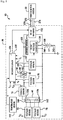
- an electric vehicle 10 having a power control system 30 in accordance with an exemplary embodiment and a vehicle motor system 50 is illustrated.
- An advantage of the power control system 30 is that the system 30 adjusts a power limit of a DC-DC voltage converter 120 based on the available power in a battery pack 60 and an amount of power being provided to a DC-AC inverter 132 which prevents the battery pack 60 from being damaged due to excessive power draw from the DC-DC voltage converter 120.
- the power control system 30 includes the battery pack 60, a voltage sensor 70, a voltage sensor 72, a voltage sensor 74, a contactor 80, a contactor driver 90, an electrical node 100, a current sensor 105, a voltage sensor 110, a temperature sensor 112, the DC-DC voltage converter 120, and a battery 130.
- the battery pack 60 has first and second battery cells 134, 136 electrically coupled in series with one another between a positive electrode 140 and a negative electrode 142.
- the battery pack 60 is adapted to generate a first voltage level between the positive electrode 140 and the negative electrode 142.
- the first battery cell 134 generates a second voltage level between a positive electrode and a negative electrode thereof.
- the second battery cell 136 generates a third voltage level between a positive electrode and a negative electrode thereof.
- the first and second battery cells 134, 136 are lithium-ion battery cells.
- the first and second battery cells 134, 136 could comprise another type of battery cell such as a nickel-cadmium battery cell, a nickel-metal-hydride battery cell, or a lead acid battery cell for example.
- the battery pack 60 outputs substantially 48 volts DC (VDC).
- VDC substantially 48 volts DC
- the battery pack 60 could output another voltage level.
- the battery pack 60 could output a voltage in a range of 300-400 VDC, or in a range greater than 400 VDC.
- the battery pack 60 could have a plurality of additional battery cells electrically coupled to one another in series with the first and second battery cells 134, 136.
- the voltage sensor 70 is electrically coupled in parallel with the battery pack 60, and further electrically coupled to the positive electrode 140 and the negative electrode 142 of the battery pack 60.
- the voltage sensor 70 is adapted to generate a voltage signal (Vp) indicative of a voltage level output by the battery pack 60.
- the microprocessor 135 receives the voltage signal (Vp) from the voltage sensor 70 and determines a first voltage value based on the voltage signal (Vp).
- the voltage sensor 72 is electrically coupled in parallel with the first battery cell 134.
- the voltage sensor 72 is adapted to generate a voltage signal (V C1 ) indicative of a voltage level output by the first battery cell 134.
- the microprocessor 135 receives the voltage signal (V C1 ) from the voltage sensor 72 and determines a second voltage value based on the voltage signal (V C1 ).
- the voltage sensor 74 is electrically coupled in parallel with the second battery cell 136.
- the voltage sensor 74 is adapted to generate a voltage signal (V C2 ) indicative of a voltage level output by the second battery cell 136.
- the microprocessor 135 receives the voltage signal (V C2 ) from the voltage sensor 74 and determines a third voltage value based on the voltage signal (V C2 ).
- the current sensor 76 is electrically coupled in series between the battery pack 60 and the contactor 80.
- the current sensor 76 is adapted to generate a current signal (I 1 ) indicative of a total current level being output by the battery pack 60.
- the microprocessor 135 receives the current signal (I 1 ) from the current sensor 76 and determines a first current value based on the current signal (I 1 ).
- the contactor 80 is electrically coupled in series with and between the first positive electrode 140 and the electrical node 100.
- the contactor 80 includes a contactor coil 82 and a contact 83.
- the contactor driver 90 When the microprocessor 135 generates a control signal that is received by the contactor driver 90, the contactor driver 90 energizes the contactor coil 82 which moves the contact 83 to a closed operational position. Alternately, when the microprocessor 135 stops generating the control signal, the contactor driver 90 de-energizes the contactor coil 82 which moves the contact 83 to an open operational position.
- the current sensor 105 is electrically coupled in series between the contactor 80 and the DC-DC voltage converter 120.
- the current sensor 105 is adapted to generate a current signal (I 2 ,) indicative of a current level being input into the DC-DC voltage converter 120.
- the microprocessor 135 receives the current signal (I 2 ) from the current sensor 105 and determines a second current value based on the current signal (I 2 ).
- the voltage sensor 110 is electrically coupled between and to the electrical node 100 and the negative electrode 142.
- the voltage sensor 110 is adapted to generate a voltage signal (V L ) indicative of a voltage level between the electrical node 100 and the negative electrode 142.
- the microprocessor 135 receives the voltage signal (V L ) from the voltage sensor 110 and determines a voltage value based on the voltage signal (V L ). If the voltage signal (V L ) is substantially equal to the voltage signal (Vp), the contact 83 is operating as desired.
- the temperature sensor 112 is disposed proximate to the battery pack 60.
- the temperature sensor 112 is adapted to generate a temperature signal (T) indicative of a temperature level of the battery pack 60.
- the microprocessor 135 receives the temperature signal (T) from the temperature sensor 112 and determines a temperature value based on the voltage signal (T).
- the DC-DC voltage converter 120 is electrically coupled between and to the electrical node 100 and the negative electrode 142.
- the DC-DC voltage converter 120 is further electrically coupled to the positive electrode 240 of the battery 130.
- the DC-DC voltage converter 120 is provided to output a voltage level between the electrical node 100 and the negative electrode 142 that is greater than a voltage level output by the battery 130, utilizing the voltage level output by the battery 130.
- the battery 130 has an positive electrode 240 and a negative electrode 242 and is utilized to provide power to auxiliary vehicle devices.
- the positive electrode 240 is electrically coupled to the DC-DC voltage converter 120.
- the negative electrode 242 is electrically coupled to the negative electrode 142 such that the negative electrode 242 and the negative electrode 142 have a common electrical ground.
- the negative electrode 242 is not electrically coupled to the negative electrode 142 such that the negative electrode 242 and the negative electrode 142 do not have a common electrical ground.
- the battery 130 is adapted to generate a voltage level between the positive electrode 240 and the negative electrode 242 which is less than a voltage level output by the battery pack 60.
- the battery 130 is a lead acid battery.
- the battery 130 could comprise another type of battery such as a nickel-cadmium battery, a nickel-metal-hydride battery, or a lithium-ion battery for example. Further, in an exemplary embodiment, the battery 130 outputs substantially 12 VDC. Of course, in an alternative embodiment, the battery 130 could output another voltage level.
- the DC-AC inverter 132 is electrically coupled between and to the electrical node 100 and the negative electrode 142 and provides AC power to the vehicle motor system 50. Further, the DC-AC inverter 132 is electrically coupled to the vehicle motor system 50 via the electrical lines 270, 272, 274. Still further, the DC-AC inverter 132 operably communicates with the microprocessor 135. When the contact 83 has the closed operational position, the DC-AC inverter 132 receives a voltage level from the battery pack 60. Further, the microprocessor 135 generates a control signal to induce the DC-AC inverter to output AC voltages on the electrical lines 270, 272, 274 to induce the vehicle motor system 50 to output a desired torque amount.
- the microprocessor 135 is operably coupled to the voltage sensor 70, the voltage sensor 72, the voltage sensor 74, the current sensor 76, the current sensor 105, the voltage sensor 110, the temperature sensor 112, the DC-DC voltage converter 120, and the DC-AC inverter 132.
- the microprocessor 135 operably communicates with a memory device 136 and stores data and operational instructions in the memory device 136.
- the microprocessor 135 is programmed to perform operational steps which will be described in greater detail below.
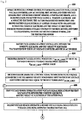
- an operator provides the power control system 30 having the battery pack 60, the DC-DC voltage converter 120, the DC-AC inverter 132, voltage sensors 70, 72, 74, current sensors 76, 105, the temperature sensor 112, and the microprocessor 135.
- the battery pack 60 has the positive electrode 140 and the negative electrode 142.
- the battery pack 60 further includes first and second battery cells 134, 136 electrically coupled in series with one another between the positive electrode 140 and the negative electrode 142.
- the microprocessor 135 is operably coupled to the voltage sensors 70, 72, 74, the current sensors 76, 105, and the temperature sensor 112.
- the battery pack 60 generates a first voltage level between the positive electrode 140 and the negative electrode 142 that is received by the DC-DC voltage converter 120 and the DC-AC inverter 132.
- the microprocessor 135 generates a control signal to induce the DC-DC voltage converter 120 to set the amount of input power being input to the DC-DC voltage converter 120 substantially equal to the input power limit P DC-DC_LIMIT .
- the generated control signal is transmitted to the DC-DC voltage converter 120.
- the voltage sensor 70 generates a first voltage signal (Vp) indicative of the first voltage level between the positive electrode 140 and the negative electrode 142 of the battery pack 60.
- the generated first voltage signal (V p ) is input to the microprocessor 135.
- the voltage sensor 72 generates a second voltage signal (V C1 ) indicative of a voltage level being output by the first battery cell 134.
- the generated second voltage signal (V C1 ) is input to the microprocessor 135.
- the voltage sensor 74 generates a third voltage signal (V C2 ) indicative of a voltage level being output by the second battery cell 136.
- the generated third voltage signal (V C2 ) is input to the microprocessor 135.
- the microprocessor 135 determines first, second, and third voltage values based on the first, second, and third voltage signals (V P , V C1 , V C2 ), respectively.
- the current sensor 76 generates a first current signal (I 1 ) indicative of a total current level flowing from the battery pack 60.
- the generated first current signal (I 1 ) is input to the microprocessor 135.
- the current sensor 105 generates a second current signal (I 2 ) indicative of a current level flowing from the battery pack 60 to the DC-DC voltage converter 120.
- the generated second current signal (I 2 ) is input to the microprocessor 135.
- the microprocessor 135 determines first and second current values based on the first and second current signals (I 1 , I 2 ), respectively.
- the temperature sensor 112 generates a temperature signal (T) indicative of a temperature of the battery pack 60.
- the microprocessor 135 determines a temperature value based on the temperature signal (T).
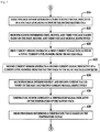
- f corresponds to a lookup table stored in the memory device 136 that utilizes the first current value, temperature value, second voltage value, and third voltage value, to look up an associated P AVAILABLE value.
- step 440 the microprocessor 135 makes a determination as to whether P DC-AC_INPUT + P DC-DC_INPUT is greater than P AVAILABLE . If the value of step 135 equals "yes”, the method advances to step 442. Otherwise, the method returns to step 408.
- the available power amount of the battery pack 60 may be preferentially allocated to the DC-AC inverter 132. Therefore, even when the battery pack 60 has a low state of charge (SOC), power may be stably supplied to the vehicle motor system 50. In addition, it is possible to prevent that the battery pack 60 is damaged since the power of the battery pack 60 is excessively consumed by the DC-DC voltage converter 120.
- SOC state of charge
- the microprocessor 35 At step 444, the microprocessor 35 generates a control signal to induce the DC-DC voltage converter 120 to set the amount of input power being input to the DC-DC voltage converter 120 substantially equal to the input power limit P DC-DC_LIMIT .
- the generated control signal is input to the DC-DC voltage converter 120.
- the above-described method can be at least partially embodied in the form of one or more memory devices or computer readable media having computer-executable instructions for practicing the methods.
- the memory devices can comprise one or more of the following: hard drives, RAM memory, flash memory, and other computer-readable media known to those skilled in the art; wherein, when the computer-executable instructions are loaded into and executed by one or more computers or microprocessors, the one or more computers or microprocessors become an apparatus programmed to practice the associated steps of the method.
- the power control system and the method described herein provide a substantial advantage over other systems and methods.
- the power control system and the method provide a technical effect of adjusting a power limit of the DC-DC voltage converter 120 based on the available power in the battery pack 60 and the amount of power being provided to the DC-AC inverter 132 which prevents the battery pack 60 from being damaged due to excessive power draw from the DC-DC voltage converter 120.
- an input power limit of a DC-DC voltage converter based on an available power of a battery pack and a power amount provided to a DC-AC inverter, it is possible to prevent the battery pack from being damaged due to excessive power drawn from the DC-DC voltage converter, and power may be stably supplied to a vehicle motor system.
Landscapes
- Engineering & Computer Science (AREA)
- Power Engineering (AREA)
- Life Sciences & Earth Sciences (AREA)
- Sustainable Development (AREA)
- Sustainable Energy (AREA)
- Transportation (AREA)
- Mechanical Engineering (AREA)
- Secondary Cells (AREA)
- Electric Propulsion And Braking For Vehicles (AREA)
- Hybrid Electric Vehicles (AREA)
- Dc-Dc Converters (AREA)
- Charge And Discharge Circuits For Batteries Or The Like (AREA)
- Inverter Devices (AREA)
Applications Claiming Priority (2)
| Application Number | Priority Date | Filing Date | Title |
|---|---|---|---|
| US14/472,405 US9935492B2 (en) | 2014-08-29 | 2014-08-29 | Power control system and method for adjusting an input power limit of a DC-DC voltage converter |
| PCT/KR2015/007747 WO2016032131A1 (ko) | 2014-08-29 | 2015-07-24 | Dc-dc 전압 변환기의 입력 파워 한도를 조절하기 위한 파워 제어 시스템 및 방법 |
Publications (3)
| Publication Number | Publication Date |
|---|---|
| EP3051677A1 EP3051677A1 (en) | 2016-08-03 |
| EP3051677A4 EP3051677A4 (en) | 2017-05-17 |
| EP3051677B1 true EP3051677B1 (en) | 2018-09-26 |
Family
ID=55399986
Family Applications (1)
| Application Number | Title | Priority Date | Filing Date |
|---|---|---|---|
| EP15836406.7A Active EP3051677B1 (en) | 2014-08-29 | 2015-07-24 | Power control system and method for controlling input power limit of dc-dc voltage converter |
Country Status (6)
| Country | Link |
|---|---|
| US (1) | US9935492B2 (ko) |
| EP (1) | EP3051677B1 (ko) |
| JP (1) | JP6348219B2 (ko) |
| KR (1) | KR101868207B1 (ko) |
| CN (1) | CN105764741B (ko) |
| WO (1) | WO2016032131A1 (ko) |
Families Citing this family (6)
| Publication number | Priority date | Publication date | Assignee | Title |
|---|---|---|---|---|
| JP6201967B2 (ja) * | 2014-11-26 | 2017-09-27 | トヨタ自動車株式会社 | 電気自動車 |
| US9921272B2 (en) | 2016-05-23 | 2018-03-20 | Lg Chem, Ltd. | System for determining a discharge power limit value and a charge power limit value of a battery cell |
| KR102055850B1 (ko) * | 2017-12-21 | 2019-12-13 | 주식회사 엘지화학 | 전류 센서 진단 장치 및 방법 |
| CN111262428B (zh) | 2020-03-02 | 2021-09-24 | 长城汽车股份有限公司 | 一种dcdc变换器的控制方法及装置 |
| KR20230070105A (ko) | 2021-11-12 | 2023-05-22 | 삼성디스플레이 주식회사 | 전원 공급 장치 및 이를 포함하는 표시 장치 |
| KR20230095191A (ko) * | 2021-12-21 | 2023-06-29 | 에이치디현대인프라코어 주식회사 | 전기동력 건설기계 |
Family Cites Families (27)
| Publication number | Priority date | Publication date | Assignee | Title |
|---|---|---|---|---|
| KR20000025249A (ko) * | 1998-10-09 | 2000-05-06 | 김영환 | 전기자동차의 전원 제어장치 및 방법 |
| JP3760820B2 (ja) * | 2000-11-14 | 2006-03-29 | トヨタ自動車株式会社 | 自動車およびその電力系統制御装置 |
| JP4023171B2 (ja) * | 2002-02-05 | 2007-12-19 | トヨタ自動車株式会社 | 負荷駆動装置、負荷駆動装置における電力貯蔵装置の充電制御方法および充電制御をコンピュータに実行させるためのプログラムを記録したコンピュータ読取可能な記録媒体 |
| JP2004063338A (ja) * | 2002-07-30 | 2004-02-26 | Nissan Motor Co Ltd | 燃料電池用電力変換装置 |
| JP2006033970A (ja) * | 2004-07-14 | 2006-02-02 | Fuji Heavy Ind Ltd | ハイブリッド車のバッテリ管理システム |
| KR101072190B1 (ko) | 2005-08-16 | 2011-10-11 | 현대자동차주식회사 | 하이브리드 전기 자동차의 돌입전류 방지장치 |
| US8872474B2 (en) * | 2006-02-09 | 2014-10-28 | Karl F. Scheucher | Fail safe serviceable high voltage battery pack |
| JP4501893B2 (ja) | 2006-04-24 | 2010-07-14 | トヨタ自動車株式会社 | 電源システムおよび車両 |
| JP4816575B2 (ja) | 2007-06-06 | 2011-11-16 | トヨタ自動車株式会社 | 電源システムおよびそれを備えた車両、ならびに電源システムの制御方法およびその制御方法をコンピュータに実行させるためのプログラムを記録したコンピュータ読取可能な記録媒体 |
| JP4640391B2 (ja) | 2007-08-10 | 2011-03-02 | トヨタ自動車株式会社 | 電源システムおよびそれを備えた車両 |
| JP4618814B2 (ja) | 2007-12-07 | 2011-01-26 | 本田技研工業株式会社 | 車両用電源装置 |
| JP2009188159A (ja) * | 2008-02-06 | 2009-08-20 | Panasonic Corp | 電力変換装置 |
| JP5288170B2 (ja) | 2008-10-03 | 2013-09-11 | 株式会社デンソー | バッテリの昇温制御装置 |
| JP5343512B2 (ja) * | 2008-10-30 | 2013-11-13 | トヨタ自動車株式会社 | 電池パック入出力制御装置 |
| GB0912379D0 (en) * | 2009-07-17 | 2009-08-26 | Rolls Royce Plc | Rotary coupling |
| JP5413017B2 (ja) | 2009-07-24 | 2014-02-12 | 株式会社豊田自動織機 | 車両用電源装置 |
| JP2011066972A (ja) | 2009-09-15 | 2011-03-31 | Fuji Electric Systems Co Ltd | モータ駆動システム |
| JP2011065972A (ja) * | 2009-09-18 | 2011-03-31 | Panasonic Electric Works Co Ltd | 放電灯点灯装置及びそれを用いた照明器具 |
| CN101860073A (zh) * | 2010-05-17 | 2010-10-13 | 艾默生网络能源有限公司 | 不间断电源系统 |
| JP5467964B2 (ja) * | 2010-08-18 | 2014-04-09 | オムロンオートモーティブエレクトロニクス株式会社 | 電力変換制御装置および電力変換制御方法 |
| JP5279797B2 (ja) * | 2010-11-01 | 2013-09-04 | 三菱電機株式会社 | 電力変換装置 |
| EP2639099A4 (en) | 2010-11-10 | 2014-08-13 | Toyota Motor Co Ltd | POWER SUPPLY SYSTEM FOR AN ELECTRIC VEHICLE, CONTROL PROCESS AND ELECTRIC VEHICLE |
| US9166515B2 (en) | 2010-12-20 | 2015-10-20 | Toyota Jidosha Kabushiki Kaisha | Electrically powered vehicle and method for controlling the same |
| KR101180801B1 (ko) * | 2011-06-30 | 2012-09-10 | 현대자동차주식회사 | 보조배터리를 이용한 전기자동차의 주행거리 증대 방법 |
| JP2013090460A (ja) * | 2011-10-19 | 2013-05-13 | Next Energy & Resources Co Ltd | 太陽光発電システムの発電制御装置 |
| JP5810879B2 (ja) * | 2011-12-13 | 2015-11-11 | トヨタ自動車株式会社 | ハイブリッド自動車 |
| WO2013132604A1 (ja) | 2012-03-07 | 2013-09-12 | トヨタ自動車株式会社 | 電動車両およびその制御方法 |
-
2014
- 2014-08-29 US US14/472,405 patent/US9935492B2/en active Active
-
2015
- 2015-07-17 KR KR1020150101775A patent/KR101868207B1/ko active IP Right Grant
- 2015-07-24 JP JP2017506889A patent/JP6348219B2/ja active Active
- 2015-07-24 CN CN201580002511.XA patent/CN105764741B/zh active Active
- 2015-07-24 WO PCT/KR2015/007747 patent/WO2016032131A1/ko active Application Filing
- 2015-07-24 EP EP15836406.7A patent/EP3051677B1/en active Active
Non-Patent Citations (1)
| Title |
|---|
| None * |
Also Published As
| Publication number | Publication date |
|---|---|
| CN105764741B (zh) | 2017-09-26 |
| EP3051677A4 (en) | 2017-05-17 |
| WO2016032131A1 (ko) | 2016-03-03 |
| KR20160026673A (ko) | 2016-03-09 |
| KR101868207B1 (ko) | 2018-07-19 |
| US20160064927A1 (en) | 2016-03-03 |
| CN105764741A (zh) | 2016-07-13 |
| US9935492B2 (en) | 2018-04-03 |
| JP2017527250A (ja) | 2017-09-14 |
| EP3051677A1 (en) | 2016-08-03 |
| JP6348219B2 (ja) | 2018-06-27 |
Similar Documents
| Publication | Publication Date | Title |
|---|---|---|
| EP3051677B1 (en) | Power control system and method for controlling input power limit of dc-dc voltage converter | |
| EP3037300B1 (en) | Temperature-raising device and temperature-raising method for in-car battery | |
| US9413184B2 (en) | Pre-charging and voltage supply system for a DC-AC inverter | |
| US9975447B2 (en) | Temperature control apparatus for electricity storage device for use in electricity storage system including electricity storage devices | |
| US8907622B2 (en) | Vehicle charging system and electrically powered vehicle provided with the same | |
| US11532841B2 (en) | Storage battery control device | |
| KR101617581B1 (ko) | 전력 제어 장치 및 방법 | |
| US9387773B2 (en) | System and method for derating a power limit associated with a battery pack | |
| EP3081425A1 (en) | Vehicle power management device | |
| EP3300160A1 (en) | Electricity storage device and connection control method | |
| US9365129B2 (en) | Vehicle having an electric motor and method of controlling a display displaying a cruising distance of the vehicle | |
| US20120280646A1 (en) | Vehicle and method for charging vehicle batteries | |
| CN103730931A (zh) | 一种适用于混合动力车辆电池系统的均衡方法 | |
| CN112352341A (zh) | 电池系统、电池管理装置 | |
| KR102417889B1 (ko) | 전기차량의 보조배터리 충전 제어장치 및 그 방법 | |
| US9748768B2 (en) | Pre-charging and voltage supply system for a DC-AC inverter | |
| US9537333B2 (en) | Voltage supply system and method for disabling operation of a DC-DC voltage converter | |
| JP6668910B2 (ja) | バッテリ容量測定装置及びバッテリ容量測定プログラム | |
| JP2018063803A (ja) | 産業車両に搭載される燃料電池システム | |
| JP6156619B2 (ja) | ハイブリッド車の作動制御装置 | |
| EP2782206B1 (en) | Battery control device | |
| JP2017085755A (ja) | 蓄電装置、輸送機器及び制御方法 | |
| CN104925008B (zh) | 对车辆中使用的电池组电池再充电的方法和充电调节器 |
Legal Events
| Date | Code | Title | Description |
|---|---|---|---|
| PUAI | Public reference made under article 153(3) epc to a published international application that has entered the european phase |
Free format text: ORIGINAL CODE: 0009012 |
|
| 17P | Request for examination filed |
Effective date: 20160426 |
|
| AK | Designated contracting states |
Kind code of ref document: A1 Designated state(s): AL AT BE BG CH CY CZ DE DK EE ES FI FR GB GR HR HU IE IS IT LI LT LU LV MC MK MT NL NO PL PT RO RS SE SI SK SM TR |
|
| AX | Request for extension of the european patent |
Extension state: BA ME |
|
| A4 | Supplementary search report drawn up and despatched |
Effective date: 20170421 |
|
| RIC1 | Information provided on ipc code assigned before grant |
Ipc: B60W 20/00 20160101ALI20170413BHEP Ipc: H02M 3/00 20060101AFI20170413BHEP Ipc: H02J 7/00 20060101ALI20170413BHEP Ipc: B60W 10/24 20060101ALI20170413BHEP Ipc: B60L 11/18 20060101ALI20170413BHEP |
|
| DAV | Request for validation of the european patent (deleted) | ||
| DAX | Request for extension of the european patent (deleted) | ||
| GRAP | Despatch of communication of intention to grant a patent |
Free format text: ORIGINAL CODE: EPIDOSNIGR1 |
|
| STAA | Information on the status of an ep patent application or granted ep patent |
Free format text: STATUS: GRANT OF PATENT IS INTENDED |
|
| INTG | Intention to grant announced |
Effective date: 20180309 |
|
| GRAJ | Information related to disapproval of communication of intention to grant by the applicant or resumption of examination proceedings by the epo deleted |
Free format text: ORIGINAL CODE: EPIDOSDIGR1 |
|
| STAA | Information on the status of an ep patent application or granted ep patent |
Free format text: STATUS: REQUEST FOR EXAMINATION WAS MADE |
|
| INTC | Intention to grant announced (deleted) | ||
| GRAP | Despatch of communication of intention to grant a patent |
Free format text: ORIGINAL CODE: EPIDOSNIGR1 |
|
| STAA | Information on the status of an ep patent application or granted ep patent |
Free format text: STATUS: GRANT OF PATENT IS INTENDED |
|
| INTG | Intention to grant announced |
Effective date: 20180529 |
|
| GRAS | Grant fee paid |
Free format text: ORIGINAL CODE: EPIDOSNIGR3 |
|
| GRAA | (expected) grant |
Free format text: ORIGINAL CODE: 0009210 |
|
| STAA | Information on the status of an ep patent application or granted ep patent |
Free format text: STATUS: THE PATENT HAS BEEN GRANTED |
|
| AK | Designated contracting states |
Kind code of ref document: B1 Designated state(s): AL AT BE BG CH CY CZ DE DK EE ES FI FR GB GR HR HU IE IS IT LI LT LU LV MC MK MT NL NO PL PT RO RS SE SI SK SM TR |
|
| REG | Reference to a national code |
Ref country code: GB Ref legal event code: FG4D |
|
| REG | Reference to a national code |
Ref country code: CH Ref legal event code: EP |
|
| REG | Reference to a national code |
Ref country code: AT Ref legal event code: REF Ref document number: 1047195 Country of ref document: AT Kind code of ref document: T Effective date: 20181015 |
|
| REG | Reference to a national code |
Ref country code: IE Ref legal event code: FG4D |
|
| REG | Reference to a national code |
Ref country code: DE Ref legal event code: R096 Ref document number: 602015017297 Country of ref document: DE |
|
| REG | Reference to a national code |
Ref country code: NL Ref legal event code: MP Effective date: 20180926 |
|
| PG25 | Lapsed in a contracting state [announced via postgrant information from national office to epo] |
Ref country code: LT Free format text: LAPSE BECAUSE OF FAILURE TO SUBMIT A TRANSLATION OF THE DESCRIPTION OR TO PAY THE FEE WITHIN THE PRESCRIBED TIME-LIMIT Effective date: 20180926 Ref country code: BG Free format text: LAPSE BECAUSE OF FAILURE TO SUBMIT A TRANSLATION OF THE DESCRIPTION OR TO PAY THE FEE WITHIN THE PRESCRIBED TIME-LIMIT Effective date: 20181226 Ref country code: SE Free format text: LAPSE BECAUSE OF FAILURE TO SUBMIT A TRANSLATION OF THE DESCRIPTION OR TO PAY THE FEE WITHIN THE PRESCRIBED TIME-LIMIT Effective date: 20180926 Ref country code: NO Free format text: LAPSE BECAUSE OF FAILURE TO SUBMIT A TRANSLATION OF THE DESCRIPTION OR TO PAY THE FEE WITHIN THE PRESCRIBED TIME-LIMIT Effective date: 20181226 Ref country code: GR Free format text: LAPSE BECAUSE OF FAILURE TO SUBMIT A TRANSLATION OF THE DESCRIPTION OR TO PAY THE FEE WITHIN THE PRESCRIBED TIME-LIMIT Effective date: 20181227 Ref country code: RS Free format text: LAPSE BECAUSE OF FAILURE TO SUBMIT A TRANSLATION OF THE DESCRIPTION OR TO PAY THE FEE WITHIN THE PRESCRIBED TIME-LIMIT Effective date: 20180926 Ref country code: FI Free format text: LAPSE BECAUSE OF FAILURE TO SUBMIT A TRANSLATION OF THE DESCRIPTION OR TO PAY THE FEE WITHIN THE PRESCRIBED TIME-LIMIT Effective date: 20180926 |
|
| REG | Reference to a national code |
Ref country code: LT Ref legal event code: MG4D |
|
| PG25 | Lapsed in a contracting state [announced via postgrant information from national office to epo] |
Ref country code: LV Free format text: LAPSE BECAUSE OF FAILURE TO SUBMIT A TRANSLATION OF THE DESCRIPTION OR TO PAY THE FEE WITHIN THE PRESCRIBED TIME-LIMIT Effective date: 20180926 Ref country code: AL Free format text: LAPSE BECAUSE OF FAILURE TO SUBMIT A TRANSLATION OF THE DESCRIPTION OR TO PAY THE FEE WITHIN THE PRESCRIBED TIME-LIMIT Effective date: 20180926 Ref country code: HR Free format text: LAPSE BECAUSE OF FAILURE TO SUBMIT A TRANSLATION OF THE DESCRIPTION OR TO PAY THE FEE WITHIN THE PRESCRIBED TIME-LIMIT Effective date: 20180926 |
|
| REG | Reference to a national code |
Ref country code: AT Ref legal event code: MK05 Ref document number: 1047195 Country of ref document: AT Kind code of ref document: T Effective date: 20180926 |
|
| PG25 | Lapsed in a contracting state [announced via postgrant information from national office to epo] |
Ref country code: IS Free format text: LAPSE BECAUSE OF FAILURE TO SUBMIT A TRANSLATION OF THE DESCRIPTION OR TO PAY THE FEE WITHIN THE PRESCRIBED TIME-LIMIT Effective date: 20190126 Ref country code: AT Free format text: LAPSE BECAUSE OF FAILURE TO SUBMIT A TRANSLATION OF THE DESCRIPTION OR TO PAY THE FEE WITHIN THE PRESCRIBED TIME-LIMIT Effective date: 20180926 Ref country code: IT Free format text: LAPSE BECAUSE OF FAILURE TO SUBMIT A TRANSLATION OF THE DESCRIPTION OR TO PAY THE FEE WITHIN THE PRESCRIBED TIME-LIMIT Effective date: 20180926 Ref country code: EE Free format text: LAPSE BECAUSE OF FAILURE TO SUBMIT A TRANSLATION OF THE DESCRIPTION OR TO PAY THE FEE WITHIN THE PRESCRIBED TIME-LIMIT Effective date: 20180926 Ref country code: CZ Free format text: LAPSE BECAUSE OF FAILURE TO SUBMIT A TRANSLATION OF THE DESCRIPTION OR TO PAY THE FEE WITHIN THE PRESCRIBED TIME-LIMIT Effective date: 20180926 Ref country code: PL Free format text: LAPSE BECAUSE OF FAILURE TO SUBMIT A TRANSLATION OF THE DESCRIPTION OR TO PAY THE FEE WITHIN THE PRESCRIBED TIME-LIMIT Effective date: 20180926 Ref country code: NL Free format text: LAPSE BECAUSE OF FAILURE TO SUBMIT A TRANSLATION OF THE DESCRIPTION OR TO PAY THE FEE WITHIN THE PRESCRIBED TIME-LIMIT Effective date: 20180926 Ref country code: RO Free format text: LAPSE BECAUSE OF FAILURE TO SUBMIT A TRANSLATION OF THE DESCRIPTION OR TO PAY THE FEE WITHIN THE PRESCRIBED TIME-LIMIT Effective date: 20180926 Ref country code: ES Free format text: LAPSE BECAUSE OF FAILURE TO SUBMIT A TRANSLATION OF THE DESCRIPTION OR TO PAY THE FEE WITHIN THE PRESCRIBED TIME-LIMIT Effective date: 20180926 |
|
| PG25 | Lapsed in a contracting state [announced via postgrant information from national office to epo] |
Ref country code: SM Free format text: LAPSE BECAUSE OF FAILURE TO SUBMIT A TRANSLATION OF THE DESCRIPTION OR TO PAY THE FEE WITHIN THE PRESCRIBED TIME-LIMIT Effective date: 20180926 Ref country code: PT Free format text: LAPSE BECAUSE OF FAILURE TO SUBMIT A TRANSLATION OF THE DESCRIPTION OR TO PAY THE FEE WITHIN THE PRESCRIBED TIME-LIMIT Effective date: 20190126 Ref country code: SK Free format text: LAPSE BECAUSE OF FAILURE TO SUBMIT A TRANSLATION OF THE DESCRIPTION OR TO PAY THE FEE WITHIN THE PRESCRIBED TIME-LIMIT Effective date: 20180926 |
|
| REG | Reference to a national code |
Ref country code: DE Ref legal event code: R097 Ref document number: 602015017297 Country of ref document: DE |
|
| PG25 | Lapsed in a contracting state [announced via postgrant information from national office to epo] |
Ref country code: DK Free format text: LAPSE BECAUSE OF FAILURE TO SUBMIT A TRANSLATION OF THE DESCRIPTION OR TO PAY THE FEE WITHIN THE PRESCRIBED TIME-LIMIT Effective date: 20180926 |
|
| PLBE | No opposition filed within time limit |
Free format text: ORIGINAL CODE: 0009261 |
|
| STAA | Information on the status of an ep patent application or granted ep patent |
Free format text: STATUS: NO OPPOSITION FILED WITHIN TIME LIMIT |
|
| 26N | No opposition filed |
Effective date: 20190627 |
|
| PG25 | Lapsed in a contracting state [announced via postgrant information from national office to epo] |
Ref country code: SI Free format text: LAPSE BECAUSE OF FAILURE TO SUBMIT A TRANSLATION OF THE DESCRIPTION OR TO PAY THE FEE WITHIN THE PRESCRIBED TIME-LIMIT Effective date: 20180926 |
|
| PG25 | Lapsed in a contracting state [announced via postgrant information from national office to epo] |
Ref country code: MC Free format text: LAPSE BECAUSE OF FAILURE TO SUBMIT A TRANSLATION OF THE DESCRIPTION OR TO PAY THE FEE WITHIN THE PRESCRIBED TIME-LIMIT Effective date: 20180926 |
|
| REG | Reference to a national code |
Ref country code: CH Ref legal event code: PL |
|
| PG25 | Lapsed in a contracting state [announced via postgrant information from national office to epo] |
Ref country code: TR Free format text: LAPSE BECAUSE OF FAILURE TO SUBMIT A TRANSLATION OF THE DESCRIPTION OR TO PAY THE FEE WITHIN THE PRESCRIBED TIME-LIMIT Effective date: 20180926 |
|
| REG | Reference to a national code |
Ref country code: BE Ref legal event code: MM Effective date: 20190731 |
|
| PG25 | Lapsed in a contracting state [announced via postgrant information from national office to epo] |
Ref country code: LU Free format text: LAPSE BECAUSE OF NON-PAYMENT OF DUE FEES Effective date: 20190724 Ref country code: BE Free format text: LAPSE BECAUSE OF NON-PAYMENT OF DUE FEES Effective date: 20190731 Ref country code: LI Free format text: LAPSE BECAUSE OF NON-PAYMENT OF DUE FEES Effective date: 20190731 Ref country code: CH Free format text: LAPSE BECAUSE OF NON-PAYMENT OF DUE FEES Effective date: 20190731 |
|
| PG25 | Lapsed in a contracting state [announced via postgrant information from national office to epo] |
Ref country code: IE Free format text: LAPSE BECAUSE OF NON-PAYMENT OF DUE FEES Effective date: 20190724 |
|
| PG25 | Lapsed in a contracting state [announced via postgrant information from national office to epo] |
Ref country code: CY Free format text: LAPSE BECAUSE OF FAILURE TO SUBMIT A TRANSLATION OF THE DESCRIPTION OR TO PAY THE FEE WITHIN THE PRESCRIBED TIME-LIMIT Effective date: 20180926 |
|
| PG25 | Lapsed in a contracting state [announced via postgrant information from national office to epo] |
Ref country code: HU Free format text: LAPSE BECAUSE OF FAILURE TO SUBMIT A TRANSLATION OF THE DESCRIPTION OR TO PAY THE FEE WITHIN THE PRESCRIBED TIME-LIMIT; INVALID AB INITIO Effective date: 20150724 Ref country code: MT Free format text: LAPSE BECAUSE OF FAILURE TO SUBMIT A TRANSLATION OF THE DESCRIPTION OR TO PAY THE FEE WITHIN THE PRESCRIBED TIME-LIMIT Effective date: 20180926 |
|
| PG25 | Lapsed in a contracting state [announced via postgrant information from national office to epo] |
Ref country code: MK Free format text: LAPSE BECAUSE OF FAILURE TO SUBMIT A TRANSLATION OF THE DESCRIPTION OR TO PAY THE FEE WITHIN THE PRESCRIBED TIME-LIMIT Effective date: 20180926 |
|
| P01 | Opt-out of the competence of the unified patent court (upc) registered |
Effective date: 20230512 |
|
| REG | Reference to a national code |
Ref country code: DE Ref legal event code: R081 Ref document number: 602015017297 Country of ref document: DE Owner name: LG ENERGY SOLUTION, LTD., KR Free format text: FORMER OWNER: LG CHEM. LTD., SEOUL, KR |
|
| REG | Reference to a national code |
Ref country code: GB Ref legal event code: 732E Free format text: REGISTERED BETWEEN 20230824 AND 20230831 |
|
| PGFP | Annual fee paid to national office [announced via postgrant information from national office to epo] |
Ref country code: DE Payment date: 20230620 Year of fee payment: 9 |
|
| PGFP | Annual fee paid to national office [announced via postgrant information from national office to epo] |
Ref country code: GB Payment date: 20240620 Year of fee payment: 10 |
|
| PGFP | Annual fee paid to national office [announced via postgrant information from national office to epo] |
Ref country code: FR Payment date: 20240624 Year of fee payment: 10 |