EP3049237B1 - Procédé pour la production d'une pièce moulée en matière plastique - Google Patents
Procédé pour la production d'une pièce moulée en matière plastique Download PDFInfo
- Publication number
- EP3049237B1 EP3049237B1 EP14772396.9A EP14772396A EP3049237B1 EP 3049237 B1 EP3049237 B1 EP 3049237B1 EP 14772396 A EP14772396 A EP 14772396A EP 3049237 B1 EP3049237 B1 EP 3049237B1
- Authority
- EP
- European Patent Office
- Prior art keywords
- surface relief
- diffractive
- mould
- provisional
- injection
- Prior art date
- Legal status (The legal status is an assumption and is not a legal conclusion. Google has not performed a legal analysis and makes no representation as to the accuracy of the status listed.)
- Active
Links
- 229920003023 plastic Polymers 0.000 title claims description 40
- 239000004033 plastic Substances 0.000 title claims description 36
- 238000000465 moulding Methods 0.000 title claims description 7
- 238000004519 manufacturing process Methods 0.000 title claims description 6
- 238000002347 injection Methods 0.000 claims description 48
- 239000007924 injection Substances 0.000 claims description 48
- 239000000758 substrate Substances 0.000 claims description 24
- 238000012937 correction Methods 0.000 claims description 23
- 238000000034 method Methods 0.000 claims description 19
- 230000000694 effects Effects 0.000 claims description 18
- 238000001746 injection moulding Methods 0.000 claims description 17
- 239000002184 metal Substances 0.000 claims description 13
- 229910052751 metal Inorganic materials 0.000 claims description 13
- 238000001459 lithography Methods 0.000 claims description 5
- 238000000151 deposition Methods 0.000 claims description 3
- 239000000654 additive Substances 0.000 claims description 2
- 230000000996 additive effect Effects 0.000 claims description 2
- 238000010894 electron beam technology Methods 0.000 claims description 2
- 238000005286 illumination Methods 0.000 claims description 2
- 229920002120 photoresistant polymer Polymers 0.000 claims description 2
- 230000008021 deposition Effects 0.000 claims 2
- 238000012986 modification Methods 0.000 claims 1
- 230000004048 modification Effects 0.000 claims 1
- 230000003287 optical effect Effects 0.000 description 29
- 238000010137 moulding (plastic) Methods 0.000 description 16
- 230000005540 biological transmission Effects 0.000 description 7
- PXHVJJICTQNCMI-UHFFFAOYSA-N Nickel Chemical compound [Ni] PXHVJJICTQNCMI-UHFFFAOYSA-N 0.000 description 6
- 238000007667 floating Methods 0.000 description 6
- 238000013461 design Methods 0.000 description 5
- 239000004922 lacquer Substances 0.000 description 5
- 230000008859 change Effects 0.000 description 4
- 239000000463 material Substances 0.000 description 4
- 230000008901 benefit Effects 0.000 description 3
- 238000005266 casting Methods 0.000 description 3
- 238000010348 incorporation Methods 0.000 description 3
- 229910052759 nickel Inorganic materials 0.000 description 3
- 230000008569 process Effects 0.000 description 3
- 239000000853 adhesive Substances 0.000 description 2
- 238000004026 adhesive bonding Methods 0.000 description 2
- 230000001070 adhesive effect Effects 0.000 description 2
- 238000011161 development Methods 0.000 description 2
- 238000009713 electroplating Methods 0.000 description 2
- 239000012778 molding material Substances 0.000 description 2
- 229920003229 poly(methyl methacrylate) Polymers 0.000 description 2
- 229920005644 polyethylene terephthalate glycol copolymer Polymers 0.000 description 2
- 239000004926 polymethyl methacrylate Substances 0.000 description 2
- 230000007704 transition Effects 0.000 description 2
- 230000003313 weakening effect Effects 0.000 description 2
- 229910000831 Steel Inorganic materials 0.000 description 1
- 229920000122 acrylonitrile butadiene styrene Polymers 0.000 description 1
- 230000002411 adverse Effects 0.000 description 1
- 238000005452 bending Methods 0.000 description 1
- 238000004364 calculation method Methods 0.000 description 1
- 238000006243 chemical reaction Methods 0.000 description 1
- 238000000576 coating method Methods 0.000 description 1
- 230000000295 complement effect Effects 0.000 description 1
- 150000001875 compounds Chemical class 0.000 description 1
- 238000001816 cooling Methods 0.000 description 1
- 238000005034 decoration Methods 0.000 description 1
- 238000000609 electron-beam lithography Methods 0.000 description 1
- 239000011888 foil Substances 0.000 description 1
- 230000001771 impaired effect Effects 0.000 description 1
- 238000003780 insertion Methods 0.000 description 1
- 230000037431 insertion Effects 0.000 description 1
- 238000009434 installation Methods 0.000 description 1
- 238000002372 labelling Methods 0.000 description 1
- 238000012423 maintenance Methods 0.000 description 1
- 238000007620 mathematical function Methods 0.000 description 1
- 239000011159 matrix material Substances 0.000 description 1
- 239000002991 molded plastic Substances 0.000 description 1
- 230000000737 periodic effect Effects 0.000 description 1
- 230000005855 radiation Effects 0.000 description 1
- 238000007493 shaping process Methods 0.000 description 1
- 239000000243 solution Substances 0.000 description 1
- 239000010959 steel Substances 0.000 description 1
- 230000000007 visual effect Effects 0.000 description 1
Images


Classifications
-
- B—PERFORMING OPERATIONS; TRANSPORTING
- B29—WORKING OF PLASTICS; WORKING OF SUBSTANCES IN A PLASTIC STATE IN GENERAL
- B29D—PRODUCING PARTICULAR ARTICLES FROM PLASTICS OR FROM SUBSTANCES IN A PLASTIC STATE
- B29D11/00—Producing optical elements, e.g. lenses or prisms
- B29D11/0074—Production of other optical elements not provided for in B29D11/00009- B29D11/0073
- B29D11/00769—Producing diffraction gratings
-
- B—PERFORMING OPERATIONS; TRANSPORTING
- B29—WORKING OF PLASTICS; WORKING OF SUBSTANCES IN A PLASTIC STATE IN GENERAL
- B29C—SHAPING OR JOINING OF PLASTICS; SHAPING OF MATERIAL IN A PLASTIC STATE, NOT OTHERWISE PROVIDED FOR; AFTER-TREATMENT OF THE SHAPED PRODUCTS, e.g. REPAIRING
- B29C45/00—Injection moulding, i.e. forcing the required volume of moulding material through a nozzle into a closed mould; Apparatus therefor
- B29C45/17—Component parts, details or accessories; Auxiliary operations
- B29C45/1756—Handling of moulds or mould parts, e.g. mould exchanging means
-
- B—PERFORMING OPERATIONS; TRANSPORTING
- B29—WORKING OF PLASTICS; WORKING OF SUBSTANCES IN A PLASTIC STATE IN GENERAL
- B29C—SHAPING OR JOINING OF PLASTICS; SHAPING OF MATERIAL IN A PLASTIC STATE, NOT OTHERWISE PROVIDED FOR; AFTER-TREATMENT OF THE SHAPED PRODUCTS, e.g. REPAIRING
- B29C45/00—Injection moulding, i.e. forcing the required volume of moulding material through a nozzle into a closed mould; Apparatus therefor
- B29C45/17—Component parts, details or accessories; Auxiliary operations
- B29C45/26—Moulds
- B29C45/263—Moulds with mould wall parts provided with fine grooves or impressions, e.g. for record discs
-
- B—PERFORMING OPERATIONS; TRANSPORTING
- B29—WORKING OF PLASTICS; WORKING OF SUBSTANCES IN A PLASTIC STATE IN GENERAL
- B29C—SHAPING OR JOINING OF PLASTICS; SHAPING OF MATERIAL IN A PLASTIC STATE, NOT OTHERWISE PROVIDED FOR; AFTER-TREATMENT OF THE SHAPED PRODUCTS, e.g. REPAIRING
- B29C45/00—Injection moulding, i.e. forcing the required volume of moulding material through a nozzle into a closed mould; Apparatus therefor
- B29C45/17—Component parts, details or accessories; Auxiliary operations
- B29C45/26—Moulds
- B29C45/2673—Moulds with exchangeable mould parts, e.g. cassette moulds
- B29C45/2675—Mounting of exchangeable mould inserts
-
- B—PERFORMING OPERATIONS; TRANSPORTING
- B29—WORKING OF PLASTICS; WORKING OF SUBSTANCES IN A PLASTIC STATE IN GENERAL
- B29C—SHAPING OR JOINING OF PLASTICS; SHAPING OF MATERIAL IN A PLASTIC STATE, NOT OTHERWISE PROVIDED FOR; AFTER-TREATMENT OF THE SHAPED PRODUCTS, e.g. REPAIRING
- B29C45/00—Injection moulding, i.e. forcing the required volume of moulding material through a nozzle into a closed mould; Apparatus therefor
- B29C45/17—Component parts, details or accessories; Auxiliary operations
- B29C45/26—Moulds
- B29C45/37—Mould cavity walls, i.e. the inner surface forming the mould cavity, e.g. linings
- B29C45/372—Mould cavity walls, i.e. the inner surface forming the mould cavity, e.g. linings provided with means for marking or patterning, e.g. numbering articles
-
- B—PERFORMING OPERATIONS; TRANSPORTING
- B29—WORKING OF PLASTICS; WORKING OF SUBSTANCES IN A PLASTIC STATE IN GENERAL
- B29D—PRODUCING PARTICULAR ARTICLES FROM PLASTICS OR FROM SUBSTANCES IN A PLASTIC STATE
- B29D11/00—Producing optical elements, e.g. lenses or prisms
- B29D11/00009—Production of simple or compound lenses
- B29D11/0048—Moulds for lenses
-
- B—PERFORMING OPERATIONS; TRANSPORTING
- B29—WORKING OF PLASTICS; WORKING OF SUBSTANCES IN A PLASTIC STATE IN GENERAL
- B29K—INDEXING SCHEME ASSOCIATED WITH SUBCLASSES B29B, B29C OR B29D, RELATING TO MOULDING MATERIALS OR TO MATERIALS FOR MOULDS, REINFORCEMENTS, FILLERS OR PREFORMED PARTS, e.g. INSERTS
- B29K2905/00—Use of metals, their alloys or their compounds, as mould material
- B29K2905/08—Transition metals
-
- B—PERFORMING OPERATIONS; TRANSPORTING
- B29—WORKING OF PLASTICS; WORKING OF SUBSTANCES IN A PLASTIC STATE IN GENERAL
- B29K—INDEXING SCHEME ASSOCIATED WITH SUBCLASSES B29B, B29C OR B29D, RELATING TO MOULDING MATERIALS OR TO MATERIALS FOR MOULDS, REINFORCEMENTS, FILLERS OR PREFORMED PARTS, e.g. INSERTS
- B29K2995/00—Properties of moulding materials, reinforcements, fillers, preformed parts or moulds
- B29K2995/0018—Properties of moulding materials, reinforcements, fillers, preformed parts or moulds having particular optical properties, e.g. fluorescent or phosphorescent
- B29K2995/0025—Opaque
-
- B—PERFORMING OPERATIONS; TRANSPORTING
- B29—WORKING OF PLASTICS; WORKING OF SUBSTANCES IN A PLASTIC STATE IN GENERAL
- B29K—INDEXING SCHEME ASSOCIATED WITH SUBCLASSES B29B, B29C OR B29D, RELATING TO MOULDING MATERIALS OR TO MATERIALS FOR MOULDS, REINFORCEMENTS, FILLERS OR PREFORMED PARTS, e.g. INSERTS
- B29K2995/00—Properties of moulding materials, reinforcements, fillers, preformed parts or moulds
- B29K2995/0018—Properties of moulding materials, reinforcements, fillers, preformed parts or moulds having particular optical properties, e.g. fluorescent or phosphorescent
- B29K2995/0026—Transparent
-
- B—PERFORMING OPERATIONS; TRANSPORTING
- B29—WORKING OF PLASTICS; WORKING OF SUBSTANCES IN A PLASTIC STATE IN GENERAL
- B29L—INDEXING SCHEME ASSOCIATED WITH SUBCLASS B29C, RELATING TO PARTICULAR ARTICLES
- B29L2011/00—Optical elements, e.g. lenses, prisms
-
- B—PERFORMING OPERATIONS; TRANSPORTING
- B29—WORKING OF PLASTICS; WORKING OF SUBSTANCES IN A PLASTIC STATE IN GENERAL
- B29L—INDEXING SCHEME ASSOCIATED WITH SUBCLASS B29C, RELATING TO PARTICULAR ARTICLES
- B29L2031/00—Other particular articles
- B29L2031/747—Lightning equipment
Definitions
- the invention relates to a method for producing a plastic molded part.
- the EP 0 878 291 A1 an injection mold for manufacturing diffractive lenses.
- the injection mold comprises two mold halves that form a lens-shaped cavity.
- One of the mold halves has a recess into which a stamp can be inserted.
- the stamp then forms the entire surface of the cavity formed by this mold half and, on its side facing the cavity, carries a structure which is molded into the plastic molded part during injection molding.
- a mold insert with a diffractive surface relief is provided, the mold insert is inserted into one mold half of an injection mold which, together with at least one other mold half, forms a cavity for producing the plastic molded part.
- the mold insert is inserted into the injection mold in such a way that the diffractive surface relief forms a partial area of the cavity surface formed by the mold half.
- the plastic molded part is then molded by injection molding using the injection mold.
- Injection molds usually include two mold halves that together form the cavity. However, multi-part forms are also conceivable. Even in the case of molds with more than two parts that together form the cavity, the respective parts are referred to here as mold halves.
- the cavity of the injection mold is understood here as that cavity of the injection mold which is complementary to the molded part to be produced and in which the plastic molded part is molded.
- Other cavities in the injection mold, such as the gating system, are not understood here as part of the cavity.
- the mold insert comprises a diffractive surface relief and can thus be inserted into a mold half of an injection mold, which together with at least one other mold half forms a cavity for producing the plastic molded part, in such a way that the diffractive surface relief forms a partial area of the surface of the cavity of the injection mold formed by the mold half .
- the injection mold for producing a plastic molding comprises at least one mold half which, together with at least one other mold half, forms a cavity for producing the plastic molding, the mold half having a receptacle into which a mold insert with a diffractive surface relief can be inserted in such a way that the diffractive surface relief has a Forms part of the inner surface formed by the mold half of the cavity of the injection mold.
- a plastic molded part produced by means of the described method using the described injection mold and the described mold insert comprises a diffractive surface relief which extends over only a partial area of a surface of the plastic molded part.
- molded plastic parts can be obtained which include diffractive optical elements, but are not necessarily designed as optical components.
- the partial areas of the surface that are not occupied by the diffractive surface relief can therefore take on additional functions.
- the diffractive surface relief can thus also serve, for example, merely for decorative purposes, for purposes of counterfeit security or as inscription.
- the partial areas of the surface not occupied by the diffractive surface relief are therefore also available for other optical functions.
- a decorative diffractive element can be combined with other non-diffractive elements such as retroreflectors or the like.
- the partial areas of the surface that are not occupied by the diffractive surface relief can also be formed in a multi-component injection molding process from another injection molding material, which in particular is not transparent. It is also possible for the partial areas of the surface not covered by the diffractive surface relief to be highly glossy and smooth and therefore preferably highly transparent and clear.
- the partial areas of the surface covered with the diffractive surface relief are not smooth or high-gloss due to the surface relief and therefore form an optical contrast to, for example, neighboring high-gloss, smooth surfaces.
- This contrast may be desirable in some practical cases and undesirable in others.
- the contrast can be somewhat concealed, for example, by transition areas between the diffractive surface relief and the adjacent high-gloss, smooth surfaces, the transition areas being slightly structured and/or having a weakening structure with a weakening towards the high-gloss, smooth surface.
- a mold insert is preferably provided as a mold insert, the diffractive surface relief of which is formed by an additive or subtractive superimposition of a diffractive microstructure and an in particular curved macrostructure.
- the macrostructure can be designed as a macroscopic curvature or generally as a free-form surface of any shape, on which the diffractive microstructure is arranged.
- the macrostructure preferably corresponds to the surface structure defined by the opposite surface of the plastic molding.
- the macrostructure is chosen such that the distance between the notional macroscopic surface of the plastic molding defined by the macrostructure and the opposite surface of the injection molded part is substantially constant, at least in a non-planar area of the diffractive surface relief, and preferably by no more than ⁇ 20 %, further preferably does not vary by more than ⁇ 10%.
- the wall thickness of a 2 mm to 3 mm thick component does not vary by more than 0.4 mm. This achieves a largely constant wall thickness of the injection molded part, as a result of which sufficiently good stability can be achieved in all areas. There are no weak points or predetermined breaking points. Accordingly, the opposite wall surfaces of the cavity of the injection mold are also spaced apart essentially constantly, at least in the area of the mold insert, so that the plastic molded part can be manufactured using the method described.
- the diffractive microstructure can thus be integrated into surfaces of any shape.
- a particular advantage is that, in contrast to known methods and injection molds, it is possible here to introduce the diffractive microstructure into curved surfaces. It is therefore not necessary to provide a flat or planar area if a diffractive microstructure is to be integrated into a component. The freedom of design in the development of plastic molded parts with diffractive surface reliefs is therefore not restricted.
- Microstructures here are preferably structures whose structural elements and/or local minima or maxima have an average spacing of less than 500 ⁇ m, preferably less than 100 ⁇ m, more preferably less than 10 ⁇ m.
- a diffractive microstructure preferably has a spatial frequency of more than 100 lines/mm, preferably more than 300 lines/mm, more preferably between 800 lines/mm to 2800 lines/mm.
- the relief depth of the diffractive microstructure is preferably between 50 nm and 100 ⁇ m, more preferably between 200 nm and 10 ⁇ m.
- CGH Computer Generated Hologram
- the microstructure is preferably designed in such a way that an optically variable effect is generated when viewed in incident light and/or viewed through transmitted light, which is visible to the human observer, if necessary with the aid of a special light source (LED, laser pointer, point light source at a predetermined spacing, etc.) becomes visible when the microstructure is molded into a preferably transparent plastics material, preferably having a refractive index of about 1.5 to 1.6.
- LED laser pointer, point light source at a predetermined spacing, etc.
- Macrostructures are preferably understood to mean structures whose structural elements and/or local minima or maxima are spaced apart from one another by more than 10 ⁇ m, preferably more than 50 ⁇ m, more preferably between 100 ⁇ m and 500 ⁇ m.
- the relief depth of the macrostructures is preferably more than 0.5 ⁇ m, more preferably more than 5 ⁇ m.
- a mold insert is provided as the mold insert, the macrostructure of which describes an at least partially curved free-form surface with one or more curvatures, the one or more curvatures each having a radius of curvature that is at least 100 times and at most 0.1 times, preferably at least 10 times and is at most 0.25 times, particularly preferably at least 5 times and at most 0.33 times the lateral extent of the diffractive surface relief, and/or the one or more curvatures each have a radius of curvature in the range from 10000 mm to 10 mm , preferably from 1000 mm to 25 mm, particularly preferably from 500 mm to 33 mm, in particular with a lateral extent of 100 mm.
- the local macroscopic curvatures of the diffractive surface relief are essentially determined by the external shape of the component, derived from the requirement for a constant wall thickness of the component.
- the lateral extent of the diffractive surface relief is understood to be the greatest distance between two points lying on the edge curve of the surface relief, ie, for example, the diameter in the case of a circular surface relief or the length of the diagonal in the case of a rectangular surface relief.
- any differently shaped contours of the surface relief are also possible, in order in particular to enable the surface relief to be integrated into the component in a way that is appealing in terms of design.
- the contour of the surface relief can be a polygon or can be delimited in some areas by constant convex and/or concave curves, in particular by means of mathematical function curves.
- the diffractive microstructure can be superimposed with the macrostructure without any problems, without the desired diffractive effect being distorted in a way that cannot be corrected.
- a preliminary diffractive surface relief is formed in a surface of a substrate, in particular in a flat metal part, and then the substrate is formed to form the mold insert, with the preliminary surface relief being deformed into the diffractive surface relief of the mold insert during the forming process.
- the substrate is preferably formed by deep drawing. It is expedient here if a tool is used for the deep-drawing, the hardness of which is less than the hardness of the material of the substrate. This ensures that the diffractive microstructure is not damaged by the deep-drawing tool.
- a master element in particular comprising a resist, is provided, into which the provisional surface relief is formed and then the substrate is molded from the master element.
- a plurality of substrates can thus be produced as copies of the master element in a simple manner. This simplifies the production compared to the direct incorporation of the preliminary surface relief into each individual substrate.
- the direct incorporation of microstructures in resists is significantly easier than the direct incorporation of microstructures in metallic substrates.
- the preliminary surface relief is preferably introduced by lithography methods such as laser beam lithography or electron beam lithography or by exposure using a mask and UV exposure in the master element and/or in the substrate, usually a radiation-sensitive resist layer (in this case by exposure and subsequent development). This enables the provisional surface relief to be molded in particularly quickly and flexibly.
- the preliminary surface relief is preferably introduced into the master element and/or the substrate as a computer-generated hologram (specifically calculated) and/or as a kinoform (specifically calculated) and/or as a Fourier hologram (holographically recorded).
- the substrate is preferably produced by galvanically depositing a metal, in particular nickel, onto the master element.
- a metal in particular nickel
- the provisional surface relief can be transferred from the master element to the harder metal substrate with high quality.
- the master element is expediently first made conductive, for example by applying a conductive lacquer. The metal can then be deposited in an electroplating bath by applying a voltage to the master element coated in this way.
- the layer thickness of the substrate deposited in this way is preferably 0.05 mm to 1 mm.
- Such substrates are strong enough to be used in mold inserts for injection molding, yet thin enough to be easily thermoformed.
- a correction function K is preferably determined for shaping the preliminary surface relief and applied to a function F1 describing the diffractive effects to be achieved in order to determine a function F2 describing the preliminary surface relief.
- correction function K characterize the change or the distortion of the provisional surface relief during the deformation and, for example, to define the macroscopic surface profile which is brought about by the deformation when a planar surface profile is deformed.
- the microstructure M to be molded for this purpose can first be determined and then this microstructure can be predistorted according to the correction function K such that the deformation caused by the deformation is compensated for again.
- F2 K ⁇ 1 * M f 1
- the determined microstructure M can be overlaid with a macrostructure (multiplicative), which is described by the inverted correction function and which represents, for example, the inverse shape of the deformation of a smooth surface (macrostructure) caused by the deformation.
- a macrostructure multiplicative
- the inverted correction function represents, for example, the inverse shape of the deformation of a smooth surface (macrostructure) caused by the deformation.
- a correction function K which describes the optical effects caused by the deformation or specifies an optical function which is necessary in order to at least partially compensate for the optical effects caused by the deformation. If, for example, the substrate is spherically deformed as a result of the reshaping, the correction function K can, for example, describe the optical function of a corresponding spherical lens or inverted spherical lens.
- correction function K describes or at least partially compensates for the change in the diffractive effects of the provisional surface relief due to the later deformation of the provisional surface relief by the reshaping.
- This correction function K is preferably applied to the function F1 describing the diffractive effects to be achieved here in such a way that the diffractive effects are calculated which, taking into account the optical effects described by the correction function K, achieve the diffractive effects to be achieved according to F1 and then from this the preliminary surface relief is determined.
- the function F1 thus describes which optical effect should occur in the finished plastic molded part. If the preliminary surface structure were formed into the substrate on the basis of function F1, the desired optical effect might not be achieved due to the deformation of the preliminary surface structure during deep-drawing in the finished plastic molded part, but instead a distorted hologram would be displayed. This is avoided by applying the correction function K to the function F1.
- the function F2 obtained thus describes which preliminary surface structure must be introduced into the substrate in order to obtain a diffractive surface structure after the deformation that produces the desired effect.
- the mold insert is fixed in the injection mold by means of a clamping element. In this way, a secure hold of the mold insert is ensured during injection molding.
- the mold insert is preferably encompassed on all sides by the clamping element and in particular held in a force-fitting and/or form-fitting manner.
- the mold insert is held on an undercut of the injection mold. This also results in a non-positive and/or form-fitting fastening, which can also have the advantage that the mold insert is flush with the surface of the cavity, so that there is no shoulder on the finished plastic molded part.
- the mold insert can also be glued to the injection mold in order to ensure a particularly secure hold.
- a corresponding receptacle in the injection mold is preferably provided for fastening the mold insert. It is expedient if at least one stamp is provided in this receptacle, by means of which a predetermined contact pressure is applied to the cavity when the mold insert is inserted side facing away from the mold insert can be exercised. This prevents the mold insert from bending during injection molding, which would lead to a deformation of the surface relief and thus to the loss of the desired optical properties of the plastic molded part.
- the mold insert has at least one marking that can be used to identify the correct orientation of the mold insert when it is inserted in the injection mold.
- the orientation of the mold insert also determines the orientation of the desired optical effect. Depending on the type of optical effect, the correct orientation or alignment can be important. For certain optical effects, however, the orientation can also be arbitrary.
- a holding device for the mold insert can also be provided, which can be inserted into a mold half of an injection mold, which together with at least one other mold half forms a cavity for producing the plastic molded part, that the diffractive surface relief of a the mold insert held in the holding device forms a partial area of the surface of the cavity of the injection mold formed by the mold half, the holding device comprising a particularly cylindrical base body in which the mold insert is inserted.
- the base body preferably has at least one undercut for holding the mold insert and/or at least one adhesive flange for gluing the mold insert to the injection mold.
- a clamping element can also be provided for holding the mold insert.
- the holding device can be closed by means of a cover.
- the cover When the mold insert is mounted, the cover then closes one end face of the cylindrical base body, while the other end face is closed by the mold insert. This results in a compact device that can be inserted into the injection mold in a simple manner and can be held there in a stable manner.
- the remaining cavity inside the base body can be filled with a suitable stamp so that the mold insert has no room to move and is not deformed during injection molding.
- stop elements can also be provided on the base body, which ensure that the base body can be mounted in the correct position in the injection mold, or which form a stop for the mold insert, so that its correct position is also ensured.
- a plastic molded part produced in this way is preferably made from a transparent or opaque plastic, in particular from PMMA, PET-G, ABS or PC.
- plastic moldings of the type described are suitable for a variety of applications.
- the plastic molded part can be part of a lighting device, in particular for a motor vehicle.
- the diffractive surface relief can be used to project a motif that appears to be floating, e.g. a logo, symbol, pattern or the like.
- Such plastic moldings can also be used in backlit switches or other operating elements.
- floating symbols can be displayed by the diffractive surface element, which clarify the function of the respective operating element.
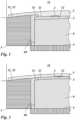
- a mold insert 3 is inserted into a receptacle 4 of an injection mold 5 .
- the mold insert 3 has the surface relief 32 to be molded on its surface 31 facing a cavity 51 of the injection mold in the inserted state. After the injection mold 5 has been closed, the cavity 51 is filled with the casting compound, so that the surface relief 32 is molded in the plastic molded part 1 .
- the surface relief 32 only forms a partial area of the surface 52 of the cavity 51 . In other words, part of the surface 11 of the plastic molding 1 remains smooth.
- the diffractive surface relief 2 can be a computer-generated hologram, a Fourier hologram or a kinoform.
- a floating image of a motif such as a symbol, logo, sign, image or the like can thus be generated in transmitted light.
- the relief preferably has a spatial frequency of between 100 lines/mm and 3000 lines/mm and/or a relief depth of 100 nm to 10 ⁇ m.
- Figures 1 and 2 show different types of attachment of the mold insert 3 in the injection mold 5.
- the mold insert 3 is held non-positively by a stamp 6 on an undercut 53 of a stamp sleeve 60 .
- a step or gap is created between the mold insert 3 between the adjacent surface of the stamp sleeve 60 and the surface relief 32 on the mold insert 3.
- the mold insert 3 is fastened in the stamp sleeve 60 by means of an undercut in a form-fitting manner and advantageously flush with the adjacent surface of the stamp sleeve 60 and is additionally glued to the stamp 6 .
- FIG. 5 shows the punch 6 with the mold insert 3 fastened thereon.
- the punch 6 has a stop 62 on its underside, so that the punch 6 only dips to a desired depth in the punch sleeve 60 and thus the mold insert 3 on the opposite side in the desired manner with the adjacent surface of the punch sleeve 60 works together.
- the stamp sleeve 60 is closed with a cover 61 on the underside, in particular screwed, in order to also fasten the stamp 6 in the stamp sleeve 60 .
- the stamp sleeve 60 is then inserted into the receptacle 4 in the injection mold 5 and is in turn fastened there by means of a screw connection.
- the stamping sleeve 60 also has a stop 63 in order to dip into the receptacle 4 of the injection mold 5 only up to a desired depth and to interact with the adjacent surface of the cavity 51 in the cavity 51 as desired.
- the tolerance or play between the receptacle 4 and the punch sleeve 60 and between the punch sleeve 60 and the punch 6 is preferably about 0.01 mm to 0.05 mm, in particular 0.02 mm to 0.03 mm.
- a flat master is first produced, which includes a layer of resist lacquer.
- a preliminary surface relief 7 is exposed in this layer. This can be done, for example, by means of a laser or electron beam or by exposure to a mask. This allows a detail resolution of about one micrometer to be achieved. Single or multiple exposures are possible, which can result in particular in two-, four- or eight-step surface profiles.
- the resist is then developed so that the preliminary surface relief is formed.
- the resist lacquer is then coated with a conductive lacquer.
- An electrical voltage is applied to the conductive lacquer layer in an electroplating bath and a metal, preferably nickel, is deposited on the master.
- the layer thickness is 0.05 mm to 1 mm.
- the metal body produced in this way now also has the provisional surface relief. Galvanic copies can in turn be made of this metal body.
- this metal body In order to be able to provide arbitrarily shaped plastic moldings 1 with a diffractive surface structure 2, this metal body must now be adapted to the shape of the plastic molding to be produced. How 3 shows, this is done by deep drawing. Here, the metal body is deformed between a stamp 8 and a counter-holder 9 until it has the desired shape. The mold insert 3 obtained in this way can, if necessary, be further cut to size and provided with fastening elements. A material that is softer than the metal body is used for the stamp 8 and counter-holder 9 . If this consists of nickel, deep-drawing tools made of steel are used, for example. As a result, the preliminary surface relief 7 is not damaged.
- curved surfaces with radii of curvature that are at least 100 times and at most 0.1 times, preferably at least 10 times and at most 0.25 times, particularly preferably at least 5 times and at most 0.33 times the lateral extent of the diffractive surface relief.
- the radii of curvature can be in the range from 10000 mm to 10 mm, preferably from 1000 mm to 25 mm, particularly preferably from 500 mm to 33 mm, in particular with a lateral extent of 100 mm.
- drawing depths of 4.8 mm with a thickness of the mold insert 3 of 0.5 mm to 1 mm or drawing depths of 2.4 mm with a thickness of the mold insert 3 of 0.5 mm can be achieved become.
- drawing depths of 10 mm can be achieved with a thickness of the mold insert 3 of 0.5 mm.
- the provisional surface relief 7 is deformed by the deep-drawing and thus changes its optical properties. This must be taken into account when designing the provisional surface relief 7 . For this reason, a preliminary surface relief 7 must be produced, which results in the desired diffractive surface relief 2 after the deformation.
- a function F1 is first determined which reproduces the desired diffractive effect.
- Such functions can, for example, be calculated and represented in the following way:
- the overall hologram is then calculated from the superimposition of all individual holograms.
- the resulting overall phase function is converted into a diffractive phase function for the design wavelength (eg red LED, wavelength 640 nm).
- the diffractive surface relief is then approximately exposed in a photoresist system.
- the "minimum feature size” determines the smallest possible structure sizes and thus the largest possible diffractive diffraction angle or largest possible additional focusing functions.
- a correction function K is also determined, which characterizes the change in the provisional surface relief during the deformation or the optical effect brought about by the deformation.
- a correction function K results in the form of a correspondingly oppositely shaped spherical curvature geometry.
- the correction function K is applied in such a way that a correction phase function that is designed opposite to the curvature geometry of the mold insert 3 is taken into account.
- the correction is particularly simple when the symmetry of the curvature of the mold insert 3 is matched to the symmetry of the motif to be represented by the diffractive surface relief 2 .
- a rotationally symmetrical motif and a correspondingly similar rotationally symmetrical curvature of the mold insert 3 can be superimposed in such a way that the two centers of symmetry lie on top of one another.
- a concrete example is a bulge in the shape of a spherical sector and a motif in the shape of a star.
- the center of the spherical sector and the center of the star preferably lie one above the other.
- distortions of the star due to the additional warping remain optically largely unproblematic and affect or impair the optical effect very little.
- by analyzing the symmetry of the camber and the motif one can find similar solutions where the camber has little disruptive effect on the desired visual effect.
- Critical variables when correcting the distortion are in particular the radius of curvature R of the diffractive surface relief 2, the lateral extent Ld of the diffractive surface relief 2, the lateral extent Li of the intensity pattern projected in transmission and the divergence angle of the light source.
- R of the diffractive surface relief 2 the radius of curvature
- Ld the lateral extent of the diffractive surface relief 2
- Li the lateral extent Li of the intensity pattern projected in transmission
- Li the lateral extent
- a further function F2 which represents the provisional surface relief 7, can be calculated by applying the correction function K to the function F1. If the provisional surface relief 7 calculated in this way is introduced into the metal body, a diffractive surface relief 2 is obtained in the finished mold insert 3 and thus also in the plastic molded part 1, which shows the desired diffractive effect.
- the plastic molded part 1 When calculating the surface reliefs 2 and 7, other parameters that are important for the desired application of the plastic molded part 1 can also be taken into account. If the plastic molded part is to be attached to an illumination device, for example, so that an optically floating symbol is generated in transmitted light, the viewing distance, viewing angle, distance from the light source, divergence angle of the light source and any focusing optics that may still be present are taken into account.
- a dedicated focusing function can also be mathematically integrated into the diffractive surface relief 7 . Particularly good results are achieved by combining the integrated focusing function with partial focusing using external optics.
- the divergence angle (half angle) of the light source should be in the range of 5° to 60°.
- the plastic molded part 1 can be produced by injection molding. If the diffractive effect is to be visible in transmitted light, transparent plastics such as PMMA (transmission 92%), PET-G (transmission 91%), ABS (transmission 85%) or PC (transmission 88%) must be used. However, surface structures that can be viewed in reflected light can also be introduced, which can be used with opaque or semi-transparent plastics or in insert molding processes. It should be noted here that the structure depths of the diffractive surface relief for elements in transmission must be many times greater than for elements that work in reflection.
- transparent plastics such as PMMA (transmission 92%), PET-G (transmission 91%), ABS (transmission 85%) or PC (transmission 88%) must be used.
- surface structures that can be viewed in reflected light can also be introduced, which can be used with opaque or semi-transparent plastics or in insert molding processes. It should be noted here that the structure depths of the diffractive surface relief for elements in transmission must be many times greater than for elements that work
- structural depths of the diffractive surface relief for elements in transmission are approximately 0.5 ⁇ m to 3 ⁇ m and the structural depths of the diffractive surface relief for elements in reflection are approximately 0.1 ⁇ m to 0.5 ⁇ m.
- such opaque plastics can advantageously contain a reflection-increasing layer in order to increase the visibility and brilliance of the optical effect of the diffractive surface relief.
- Insertion of the mold insert 3 does not adversely affect the cycle time of the molding process. This mainly depends on the geometry and size, as well as on the wall thickness of the plastic molded part 1, because the cooling time of the injection molding material is determined by these variables, in particular primarily by the wall thickness.
- the cycle time of the casting process is usually between 5 seconds and 180 seconds, in particular between 10 seconds and 180 seconds.
- the diffractive surface relief 2 is thereby irradiated with light, which by means of a focusing element achieves the desired divergence having.
- Light source 7 and diffractive surface relief 3 are arranged at a distance L.
- the distance L is preferably about 0.5 cm to about 10 cm.
- the light shining through the diffractive surface relief 2 produces an optical effect 73 which can be seen at the viewing distance A with the unaided human eye, ie without further aids.
- the viewing distance A is preferably about 20 cm to 500 cm. However, the effect 73 is also visible outside of this area.
- a quasi-continuous, diffractive phase function is calculated as a computer-generated hologram, which is generated in diffractive relief structures with the smallest local grating periods of approx. 5 ⁇ m to 10 ⁇ m and structure depths of approx. 1 ⁇ m to 1.5 ⁇ m results.
- the diffractive surface relief 2 contains the remaining correction of the beam path of the light necessary for the desired divergence of the light or the desired optical effect, with this correction on the path of the macrostructure (in this example the component curvature is a spherical deformation) is adjusted.
- the in 4 A red LED with a divergence angle (half angle) of 45 degrees is used as the light source 71 for illuminating or backlighting the transparent plastic material of the plastic molding 1 .
- the additional focusing optics 72 is used as a Formed convex lens with a focal length of 40 mm and a diameter of 20 mm.
- the distance between the LED 71 and the focusing optics 72 is 10 mm, the distance between the focusing optics 72 and the diffractive surface relief 2 is approximately 40 mm.
- the surface of the plastic molded part 1 forms a spherical shell with a radius of curvature of 120 mm.
- the diffractive surface relief 3 is circular with a diameter of about 35 mm.
- An optical effect 73 results in the form of a star with a size of approx. 30 mm ⁇ 30 mm, which appears to be approx. 5 cm to 10 cm behind the diffractive surface structure 2 as seen from the viewer.
- the ideal observer distance is approx. 4 m to 5 m in front of the diffractive surface structure 2; the viewer can be positioned slightly offset from the optical axis, e.g. slightly higher or lower.
- a variety of plastic moldings 1 can be produced in the manner described. Since the diffractive surface relief 2 can be arranged on any free-form surface, the design freedom when designing the plastic molded part is not impaired. In particular, diffractive effects can be integrated into existing designs without further changes being necessary.
- the diffractive surface relief 2 occupies only a portion of the surface 11 of the plastic molding 1, other optical or other functions can also be integrated into the plastic molding.
- Possible applications are, for example, lighting devices that project optically floating motifs (apparently lying in front of or behind the plane of the component), backlit switches or controls whose function is indicated by an optically floating symbol, and the like.
Claims (7)
- Procédé de fabrication d'une pièce moulée en matière plastique (1), dans lequel un insert de moulage (3) avec un relief superficiel diffractif (32) est fourni dans le procédé, l'insert de moulage (3) est inséré dans un demi-moule d'un moule de coulée par injection (5), lequel réalise, conjointement avec au moins un autre demi-moule, une cavité pour fabriquer la pièce moulée en matière plastique (1), dans lequel l'insert de moulage (3) est inséré de telle sorte dans le moule de coulée par injection (5) que le relief superficiel diffractif (32) réalise une zone partielle de la surface, formée par le demi-moule (5), de la cavité, et la pièce moulée en matière plastique (1) est moulée au moyen du moule de coulée par injection (5) par coulée par injection, dans lequel un relief superficiel diffractif temporaire est réalisé dans une surface d'un substrat lors de la fourniture de l'insert de moulage (3) puis le substrat est mis en forme pour réaliser l'insert de moulage (3), dans lequel lors de la mise en forme, le relief superficiel temporaire est déformé en le relief superficiel diffractif (32) de l'insert de moulage (3).
- Procédé selon la revendication 1,
caractérisé en ce
qu'est fourni en tant qu'insert de moulage (3) un insert de moulage (3) dont le relief superficiel diffractif (32) est réalisé par une superposition par addition ou par soustraction d'une microstructure diffractive et d'une macrostructure incurvée. - Procédé selon la revendication 2,
caractérisé en ce
qu'est fourni en tant qu'insert de moulage (3) un insert de moulage (3), dont la macrostructure décrit une face de moulage libre incurvée au moins par endroits avec une ou plusieurs incurvations, dans lequel les une ou plusieurs incurvations présentent respectivement un rayon d'incurvation, qui représente au moins 100 fois et au maximum 0,1 fois l'extension latérale du relief superficiel diffractif, et/ou les une ou plusieurs incurvations présentent respectivement un rayon d'incurvation dans la plage de 10 000 mm à 10 mm, de manière préférée de 1000 mm à 25 mm. - Procédé selon l'une quelconque des revendications précédentes,
caractérisé en ce
que pour réaliser le relief superficiel temporaire, un élément maître, comprenant en particulier une laque de résist, est fourni en premier lieu, dans lequel le relief superficiel temporaire est pratiqué, puis le substrat est moulé par l'élément maître, dans lequel le relief superficiel temporaire est pratiqué dans l'élément maître et/ou dans le substrat par lithographie et/ou au moyen d'un faisceau laser ou électronique et/ou par exposition à la lumière au moyen d'un masque. - Procédé selon la revendication 4,
caractérisé en ce
qu'une fois le relief superficiel diffractif pratiqué, le substrat est produit par séparation galvanique d'un métal sur l'élément maître, dans lequel d'autres substrats sont produits par séparation galvanique d'un métal par le substrat produit. - Procédé selon l'une quelconque des revendications précédentes,
caractérisé en ce
que pour pratiquer le relief superficiel temporaire, une fonction de correction (K) est déterminée et est appliquée sur une fonction (F1) décrivant les effets diffractifs à obtenir pour définir une fonction (F2) décrivant le relief superficiel temporaire, dans lequel la fonction de correction (K) décrit ou compense au moins en partie en particulier la modification des effets diffractifs du relief superficiel temporaire par la déformation ultérieure du relief superficiel temporaire par la mise en forme. - Procédé selon l'une quelconque des revendications précédentes,
caractérisé en ce
que l'insert de moulage (3) est fixé dans le moule de coulée par injection (5) au moyen d'un élément de serrage et/ou est maintenu sur une contre-dépouille du moule de coulée par injection et/ou est collé au moule de coulée par injection (5).
Applications Claiming Priority (2)
| Application Number | Priority Date | Filing Date | Title |
|---|---|---|---|
| DE102013110702.8A DE102013110702B4 (de) | 2013-09-27 | 2013-09-27 | Verfahren, Formeinsatz und Spritzgussform zum Herstellen eines Kunststoffformteils |
| PCT/EP2014/070573 WO2015044314A1 (fr) | 2013-09-27 | 2014-09-25 | Procédé, insert de formage et moule d'injection pour la production d'une pièce moulée en matière plastique |
Publications (2)
| Publication Number | Publication Date |
|---|---|
| EP3049237A1 EP3049237A1 (fr) | 2016-08-03 |
| EP3049237B1 true EP3049237B1 (fr) | 2023-05-31 |
Family
ID=51619207
Family Applications (1)
| Application Number | Title | Priority Date | Filing Date |
|---|---|---|---|
| EP14772396.9A Active EP3049237B1 (fr) | 2013-09-27 | 2014-09-25 | Procédé pour la production d'une pièce moulée en matière plastique |
Country Status (8)
| Country | Link |
|---|---|
| US (1) | US10315370B2 (fr) |
| EP (1) | EP3049237B1 (fr) |
| JP (1) | JP6668581B2 (fr) |
| KR (1) | KR102211514B1 (fr) |
| CN (1) | CN105593005B (fr) |
| DE (1) | DE102013110702B4 (fr) |
| MX (1) | MX2016003759A (fr) |
| WO (1) | WO2015044314A1 (fr) |
Families Citing this family (5)
| Publication number | Priority date | Publication date | Assignee | Title |
|---|---|---|---|---|
| ES2567097B2 (es) * | 2015-12-28 | 2016-10-10 | Seat, S.A. | Molde de inyección y procedimiento para la fabricación de un módulo óptico para un dispositivo de iluminación de un vehículo, y módulo óptico fabricado mediante dicho molde y/o mediante dicho procedimiento |
| KR102565788B1 (ko) * | 2016-06-23 | 2023-08-10 | 엘지이노텍 주식회사 | 차량용 램프 및 이를 포함하는 차량 |
| EP3547042A1 (fr) * | 2018-03-29 | 2019-10-02 | ETA SA Manufacture Horlogère Suisse | Procédé et système de fabrication d'au moins un élément horloger destiné à être rapporté sur un composant horloger d'une pièce d'horlogerie |
| CN110126199B (zh) * | 2019-05-17 | 2021-11-23 | 广东邦孚光学有限公司 | 一种带锯齿的透镜加工工艺 |
| CN110126146A (zh) * | 2019-05-30 | 2019-08-16 | 开平市盈光机电科技有限公司 | 一种带立体纹理的移动模模芯 |
Citations (1)
| Publication number | Priority date | Publication date | Assignee | Title |
|---|---|---|---|---|
| US20020181224A1 (en) * | 2001-04-12 | 2002-12-05 | Hisashi Tahara | Light guide plate made of transparent resin, molding method thereof, insert block, mold assembly, and area light apparatus |
Family Cites Families (18)
| Publication number | Priority date | Publication date | Assignee | Title |
|---|---|---|---|---|
| US4747981A (en) | 1985-10-07 | 1988-05-31 | Robinson Jesse L | Method of molding a urethane reflector |
| AU1343092A (en) * | 1992-01-09 | 1993-08-03 | Scott R. Fohrman | Reproduction of holograms |
| US5538674A (en) * | 1993-11-19 | 1996-07-23 | Donnelly Corporation | Method for reproducing holograms, kinoforms, diffractive optical elements and microstructures |
| WO1996016794A1 (fr) * | 1994-11-28 | 1996-06-06 | Aotec, Inc. | Procede et appareil de fabrication de lentilles a diffraction en plastique |
| US5728324A (en) | 1995-01-31 | 1998-03-17 | Digital Optics Corporation | Molding diffractive optical elements |
| US5958469A (en) | 1997-05-14 | 1999-09-28 | Eastman Kodak Company | Method for fabricating tools for molding diffractive surfaces on optical lenses |
| JP2000214884A (ja) * | 1999-01-22 | 2000-08-04 | Olympus Optical Co Ltd | 音声記録装置 |
| US7306827B2 (en) * | 2000-10-30 | 2007-12-11 | Sru Biosystems, Inc. | Method and machine for replicating holographic gratings on a substrate |
| TW548173B (en) * | 2001-07-10 | 2003-08-21 | Cinpres Gas Injection Ltd | Process and apparatus for injection moulding a hollow plastics article |
| US20040219464A1 (en) | 2003-05-01 | 2004-11-04 | Dunham Gregory David | Diffractive optical elements formed on plastic surface and method of making |
| DE10333370A1 (de) * | 2003-07-23 | 2005-02-24 | Schott Ag | Beleuchtungseinrichtung, Linse und Herstellung der Linse |
| JP4815898B2 (ja) * | 2004-06-29 | 2011-11-16 | コニカミノルタオプト株式会社 | 射出成形用金型及び射出成形方法 |
| CN1715033A (zh) * | 2004-06-29 | 2006-01-04 | 柯尼卡美能达精密光学株式会社 | 注射成形用模具和光学元件的成形方法 |
| JP2008173914A (ja) * | 2007-01-22 | 2008-07-31 | Toppan Printing Co Ltd | 微細凹凸パターンの転写方法及び転写箔 |
| JP5140517B2 (ja) * | 2008-08-07 | 2013-02-06 | アピックヤマダ株式会社 | 樹脂モールド装置および樹脂モールド方法 |
| KR101537619B1 (ko) | 2009-09-09 | 2015-07-17 | 엘지전자 주식회사 | 사출금형용 스탬퍼 제작방법 |
| KR101021061B1 (ko) | 2010-06-30 | 2011-03-11 | 주식회사 재팬레이저 | 반사 방지용 디스플레이 윈도우 패널의 제조 방법 |
| WO2012006637A1 (fr) * | 2010-07-09 | 2012-01-12 | Pixeloptics, Inc. | Moule pour lentille ophtalmique diffractive |
-
2013
- 2013-09-27 DE DE102013110702.8A patent/DE102013110702B4/de active Active
-
2014
- 2014-09-25 JP JP2016517344A patent/JP6668581B2/ja active Active
- 2014-09-25 US US15/024,108 patent/US10315370B2/en not_active Expired - Fee Related
- 2014-09-25 EP EP14772396.9A patent/EP3049237B1/fr active Active
- 2014-09-25 WO PCT/EP2014/070573 patent/WO2015044314A1/fr active Application Filing
- 2014-09-25 CN CN201480053092.8A patent/CN105593005B/zh active Active
- 2014-09-25 KR KR1020167011013A patent/KR102211514B1/ko active IP Right Grant
- 2014-09-25 MX MX2016003759A patent/MX2016003759A/es unknown
Patent Citations (1)
| Publication number | Priority date | Publication date | Assignee | Title |
|---|---|---|---|---|
| US20020181224A1 (en) * | 2001-04-12 | 2002-12-05 | Hisashi Tahara | Light guide plate made of transparent resin, molding method thereof, insert block, mold assembly, and area light apparatus |
Also Published As
| Publication number | Publication date |
|---|---|
| MX2016003759A (es) | 2016-07-08 |
| KR20160062108A (ko) | 2016-06-01 |
| JP6668581B2 (ja) | 2020-03-18 |
| KR102211514B1 (ko) | 2021-02-04 |
| US20160229137A1 (en) | 2016-08-11 |
| JP2016531763A (ja) | 2016-10-13 |
| DE102013110702B4 (de) | 2019-11-14 |
| EP3049237A1 (fr) | 2016-08-03 |
| DE102013110702A1 (de) | 2015-04-02 |
| CN105593005B (zh) | 2018-10-02 |
| US10315370B2 (en) | 2019-06-11 |
| WO2015044314A1 (fr) | 2015-04-02 |
| CN105593005A (zh) | 2016-05-18 |
Similar Documents
| Publication | Publication Date | Title |
|---|---|---|
| EP3049237B1 (fr) | Procédé pour la production d'une pièce moulée en matière plastique | |
| DE112007001425B4 (de) | Fälschungssicheres Hologramm, Verfahren zu dessen Herstellung und Vorrichtung zur Durchführung dieses Verfahrens | |
| EP2038124B1 (fr) | Procédé pour appliquer une microstructure, moule d'outil et objet doté d'une microstructure | |
| EP1851069B1 (fr) | Film a plusieurs couches, article moule par injection decore dudit film et procede de production de l'article moule par injection decore | |
| EP3216620B1 (fr) | Élement de securite, document de valeur dote d'un tel element de securite ainsi que procede de fabrication d'un element de securite | |
| EP2589479B1 (fr) | Procédé de fabrication de réflecteurs | |
| DE102020005896A1 (de) | Verfahren zur Herstellung eines flächigen Verkleidungselementes für ein Fahrzeug | |
| DE102015121691A1 (de) | Verfahren zur Herstellung eines Mikrolinsenarrays | |
| EP3606765B1 (fr) | Elément de sécurité avec structure en relief et son procédé de fabrication | |
| DE102017104433A1 (de) | Verfahren zur Herstellung eines Kunststoffbauteils mit einem Schichtverbund und einem angespritzten Kunststoffkörper | |
| EP3727871A2 (fr) | Document de valeurs | |
| WO1998001278A1 (fr) | Cylindre graineur pour produire des feuilles grainees | |
| EP2561408A1 (fr) | Objet fabriqué selon un procédé de moulage et marqué avec une grille de diffraction, et son procédé de fabrication | |
| EP3034315B1 (fr) | Élement de securite, son procede de fabrication et support de donnees dote d'un element de securite | |
| EP3356868A1 (fr) | Panneau routier rétroréfléchissant, matériau en bande rétroréfléchissant et procédé de fabrication associé | |
| DE202009014165U1 (de) | Vorrichtung zum Spritzgießen von Kunststoffbauteilen und Verwendung dieser Vorrichtung sowie Spritzgießteile | |
| DE102020209106B4 (de) | Verfahren zum Bereitstellen eines Prägeelements für ein Prägewerkzeug, ein Prägeelement, eine Verwendung eines Prägeelements und ein Prägewerkzeug umfassend ein Prägeelement | |
| DE4340107B4 (de) | Verfahren zur Herstellung eines Teils mit einer fein strukturierten konkaven Oberfläche | |
| DE19780654B4 (de) | Prägezylinder für die Herstellung von Prägefolien | |
| EP3239362B1 (fr) | Procede de production de structures de diffraction de la lumiere sur un outil a stratifier | |
| DE102016104300A1 (de) | Sicherheitselement sowie ein Verfahren zur Herstellung eines Sicherheitselements | |
| DE102015212885A1 (de) | Verfahren zur Herstellung eines Hologramms | |
| WO2024061528A1 (fr) | Élément moulé par injection et procédé de fabrication d'un élément moulé par injection | |
| DE102022104830A1 (de) | Werkstückbildungsvorrichtung und Verfahren zum Herstellen eines Faserverbundwerkstücks | |
| DE102012025264A1 (de) | Verfahren zur Herstellung eines Sicherheitselementes |
Legal Events
| Date | Code | Title | Description |
|---|---|---|---|
| TPAC | Observations filed by third parties |
Free format text: ORIGINAL CODE: EPIDOSNTIPA |
|
| PUAI | Public reference made under article 153(3) epc to a published international application that has entered the european phase |
Free format text: ORIGINAL CODE: 0009012 |
|
| STAA | Information on the status of an ep patent application or granted ep patent |
Free format text: STATUS: REQUEST FOR EXAMINATION WAS MADE |
|
| 17P | Request for examination filed |
Effective date: 20160418 |
|
| AK | Designated contracting states |
Kind code of ref document: A1 Designated state(s): AL AT BE BG CH CY CZ DE DK EE ES FI FR GB GR HR HU IE IS IT LI LT LU LV MC MK MT NL NO PL PT RO RS SE SI SK SM TR |
|
| AX | Request for extension of the european patent |
Extension state: BA ME |
|
| DAX | Request for extension of the european patent (deleted) | ||
| RAP1 | Party data changed (applicant data changed or rights of an application transferred) |
Owner name: OVD KINEGRAM AG Owner name: LEONHARD KURZ STIFTUNG & CO. KG |
|
| STAA | Information on the status of an ep patent application or granted ep patent |
Free format text: STATUS: EXAMINATION IS IN PROGRESS |
|
| 17Q | First examination report despatched |
Effective date: 20210303 |
|
| STAA | Information on the status of an ep patent application or granted ep patent |
Free format text: STATUS: EXAMINATION IS IN PROGRESS |
|
| GRAP | Despatch of communication of intention to grant a patent |
Free format text: ORIGINAL CODE: EPIDOSNIGR1 |
|
| STAA | Information on the status of an ep patent application or granted ep patent |
Free format text: STATUS: GRANT OF PATENT IS INTENDED |
|
| TPAC | Observations filed by third parties |
Free format text: ORIGINAL CODE: EPIDOSNTIPA |
|
| INTG | Intention to grant announced |
Effective date: 20230316 |
|
| GRAS | Grant fee paid |
Free format text: ORIGINAL CODE: EPIDOSNIGR3 |
|
| GRAA | (expected) grant |
Free format text: ORIGINAL CODE: 0009210 |
|
| STAA | Information on the status of an ep patent application or granted ep patent |
Free format text: STATUS: THE PATENT HAS BEEN GRANTED |
|
| AK | Designated contracting states |
Kind code of ref document: B1 Designated state(s): AL AT BE BG CH CY CZ DE DK EE ES FI FR GB GR HR HU IE IS IT LI LT LU LV MC MK MT NL NO PL PT RO RS SE SI SK SM TR |
|
| REG | Reference to a national code |
Ref country code: GB Ref legal event code: FG4D Free format text: NOT ENGLISH Ref country code: CH Ref legal event code: EP |
|
| REG | Reference to a national code |
Ref country code: DE Ref legal event code: R096 Ref document number: 502014016576 Country of ref document: DE |
|
| REG | Reference to a national code |
Ref country code: AT Ref legal event code: REF Ref document number: 1570707 Country of ref document: AT Kind code of ref document: T Effective date: 20230615 |
|
| REG | Reference to a national code |
Ref country code: IE Ref legal event code: FG4D Free format text: LANGUAGE OF EP DOCUMENT: GERMAN |
|
| REG | Reference to a national code |
Ref country code: LT Ref legal event code: MG9D |
|
| REG | Reference to a national code |
Ref country code: NL Ref legal event code: MP Effective date: 20230531 |
|
| PG25 | Lapsed in a contracting state [announced via postgrant information from national office to epo] |
Ref country code: SE Free format text: LAPSE BECAUSE OF FAILURE TO SUBMIT A TRANSLATION OF THE DESCRIPTION OR TO PAY THE FEE WITHIN THE PRESCRIBED TIME-LIMIT Effective date: 20230531 Ref country code: NO Free format text: LAPSE BECAUSE OF FAILURE TO SUBMIT A TRANSLATION OF THE DESCRIPTION OR TO PAY THE FEE WITHIN THE PRESCRIBED TIME-LIMIT Effective date: 20230831 Ref country code: ES Free format text: LAPSE BECAUSE OF FAILURE TO SUBMIT A TRANSLATION OF THE DESCRIPTION OR TO PAY THE FEE WITHIN THE PRESCRIBED TIME-LIMIT Effective date: 20230531 |
|
| PGFP | Annual fee paid to national office [announced via postgrant information from national office to epo] |
Ref country code: AT Payment date: 20230915 Year of fee payment: 10 |
|
| PG25 | Lapsed in a contracting state [announced via postgrant information from national office to epo] |
Ref country code: RS Free format text: LAPSE BECAUSE OF FAILURE TO SUBMIT A TRANSLATION OF THE DESCRIPTION OR TO PAY THE FEE WITHIN THE PRESCRIBED TIME-LIMIT Effective date: 20230531 Ref country code: PL Free format text: LAPSE BECAUSE OF FAILURE TO SUBMIT A TRANSLATION OF THE DESCRIPTION OR TO PAY THE FEE WITHIN THE PRESCRIBED TIME-LIMIT Effective date: 20230531 Ref country code: NL Free format text: LAPSE BECAUSE OF FAILURE TO SUBMIT A TRANSLATION OF THE DESCRIPTION OR TO PAY THE FEE WITHIN THE PRESCRIBED TIME-LIMIT Effective date: 20230531 Ref country code: LV Free format text: LAPSE BECAUSE OF FAILURE TO SUBMIT A TRANSLATION OF THE DESCRIPTION OR TO PAY THE FEE WITHIN THE PRESCRIBED TIME-LIMIT Effective date: 20230531 Ref country code: LT Free format text: LAPSE BECAUSE OF FAILURE TO SUBMIT A TRANSLATION OF THE DESCRIPTION OR TO PAY THE FEE WITHIN THE PRESCRIBED TIME-LIMIT Effective date: 20230531 Ref country code: IS Free format text: LAPSE BECAUSE OF FAILURE TO SUBMIT A TRANSLATION OF THE DESCRIPTION OR TO PAY THE FEE WITHIN THE PRESCRIBED TIME-LIMIT Effective date: 20230930 Ref country code: HR Free format text: LAPSE BECAUSE OF FAILURE TO SUBMIT A TRANSLATION OF THE DESCRIPTION OR TO PAY THE FEE WITHIN THE PRESCRIBED TIME-LIMIT Effective date: 20230531 Ref country code: GR Free format text: LAPSE BECAUSE OF FAILURE TO SUBMIT A TRANSLATION OF THE DESCRIPTION OR TO PAY THE FEE WITHIN THE PRESCRIBED TIME-LIMIT Effective date: 20230901 |
|
| PGFP | Annual fee paid to national office [announced via postgrant information from national office to epo] |
Ref country code: FR Payment date: 20230915 Year of fee payment: 10 Ref country code: DE Payment date: 20230830 Year of fee payment: 10 |
|
| PG25 | Lapsed in a contracting state [announced via postgrant information from national office to epo] |
Ref country code: FI Free format text: LAPSE BECAUSE OF FAILURE TO SUBMIT A TRANSLATION OF THE DESCRIPTION OR TO PAY THE FEE WITHIN THE PRESCRIBED TIME-LIMIT Effective date: 20230531 |
|
| PG25 | Lapsed in a contracting state [announced via postgrant information from national office to epo] |
Ref country code: SK Free format text: LAPSE BECAUSE OF FAILURE TO SUBMIT A TRANSLATION OF THE DESCRIPTION OR TO PAY THE FEE WITHIN THE PRESCRIBED TIME-LIMIT Effective date: 20230531 |
|
| PG25 | Lapsed in a contracting state [announced via postgrant information from national office to epo] |
Ref country code: SM Free format text: LAPSE BECAUSE OF FAILURE TO SUBMIT A TRANSLATION OF THE DESCRIPTION OR TO PAY THE FEE WITHIN THE PRESCRIBED TIME-LIMIT Effective date: 20230531 Ref country code: SK Free format text: LAPSE BECAUSE OF FAILURE TO SUBMIT A TRANSLATION OF THE DESCRIPTION OR TO PAY THE FEE WITHIN THE PRESCRIBED TIME-LIMIT Effective date: 20230531 Ref country code: RO Free format text: LAPSE BECAUSE OF FAILURE TO SUBMIT A TRANSLATION OF THE DESCRIPTION OR TO PAY THE FEE WITHIN THE PRESCRIBED TIME-LIMIT Effective date: 20230531 Ref country code: PT Free format text: LAPSE BECAUSE OF FAILURE TO SUBMIT A TRANSLATION OF THE DESCRIPTION OR TO PAY THE FEE WITHIN THE PRESCRIBED TIME-LIMIT Effective date: 20231002 Ref country code: EE Free format text: LAPSE BECAUSE OF FAILURE TO SUBMIT A TRANSLATION OF THE DESCRIPTION OR TO PAY THE FEE WITHIN THE PRESCRIBED TIME-LIMIT Effective date: 20230531 Ref country code: DK Free format text: LAPSE BECAUSE OF FAILURE TO SUBMIT A TRANSLATION OF THE DESCRIPTION OR TO PAY THE FEE WITHIN THE PRESCRIBED TIME-LIMIT Effective date: 20230531 Ref country code: CZ Free format text: LAPSE BECAUSE OF FAILURE TO SUBMIT A TRANSLATION OF THE DESCRIPTION OR TO PAY THE FEE WITHIN THE PRESCRIBED TIME-LIMIT Effective date: 20230531 |
|
| PGFP | Annual fee paid to national office [announced via postgrant information from national office to epo] |
Ref country code: IT Payment date: 20230929 Year of fee payment: 10 Ref country code: CH Payment date: 20231001 Year of fee payment: 10 |
|
| REG | Reference to a national code |
Ref country code: DE Ref legal event code: R097 Ref document number: 502014016576 Country of ref document: DE |
|
| PLBE | No opposition filed within time limit |
Free format text: ORIGINAL CODE: 0009261 |
|
| STAA | Information on the status of an ep patent application or granted ep patent |
Free format text: STATUS: NO OPPOSITION FILED WITHIN TIME LIMIT |
|
| PG25 | Lapsed in a contracting state [announced via postgrant information from national office to epo] |
Ref country code: SI Free format text: LAPSE BECAUSE OF FAILURE TO SUBMIT A TRANSLATION OF THE DESCRIPTION OR TO PAY THE FEE WITHIN THE PRESCRIBED TIME-LIMIT Effective date: 20230531 |
|
| 26N | No opposition filed |
Effective date: 20240301 |