EP3049237B1 - Method for producing a plastics moulding - Google Patents
Method for producing a plastics moulding Download PDFInfo
- Publication number
- EP3049237B1 EP3049237B1 EP14772396.9A EP14772396A EP3049237B1 EP 3049237 B1 EP3049237 B1 EP 3049237B1 EP 14772396 A EP14772396 A EP 14772396A EP 3049237 B1 EP3049237 B1 EP 3049237B1
- Authority
- EP
- European Patent Office
- Prior art keywords
- surface relief
- diffractive
- mould
- provisional
- injection
- Prior art date
- Legal status (The legal status is an assumption and is not a legal conclusion. Google has not performed a legal analysis and makes no representation as to the accuracy of the status listed.)
- Active
Links
- 229920003023 plastic Polymers 0.000 title claims description 40
- 239000004033 plastic Substances 0.000 title claims description 36
- 238000000465 moulding Methods 0.000 title claims description 7
- 238000004519 manufacturing process Methods 0.000 title claims description 6
- 238000002347 injection Methods 0.000 claims description 48
- 239000007924 injection Substances 0.000 claims description 48
- 239000000758 substrate Substances 0.000 claims description 24
- 238000012937 correction Methods 0.000 claims description 23
- 238000000034 method Methods 0.000 claims description 19
- 230000000694 effects Effects 0.000 claims description 18
- 238000001746 injection moulding Methods 0.000 claims description 17
- 239000002184 metal Substances 0.000 claims description 13
- 229910052751 metal Inorganic materials 0.000 claims description 13
- 238000001459 lithography Methods 0.000 claims description 5
- 238000000151 deposition Methods 0.000 claims description 3
- 239000000654 additive Substances 0.000 claims description 2
- 230000000996 additive effect Effects 0.000 claims description 2
- 238000010894 electron beam technology Methods 0.000 claims description 2
- 238000005286 illumination Methods 0.000 claims description 2
- 229920002120 photoresistant polymer Polymers 0.000 claims description 2
- 230000008021 deposition Effects 0.000 claims 2
- 238000012986 modification Methods 0.000 claims 1
- 230000004048 modification Effects 0.000 claims 1
- 230000003287 optical effect Effects 0.000 description 29
- 238000010137 moulding (plastic) Methods 0.000 description 16
- 230000005540 biological transmission Effects 0.000 description 7
- PXHVJJICTQNCMI-UHFFFAOYSA-N Nickel Chemical compound [Ni] PXHVJJICTQNCMI-UHFFFAOYSA-N 0.000 description 6
- 238000007667 floating Methods 0.000 description 6
- 238000013461 design Methods 0.000 description 5
- 239000004922 lacquer Substances 0.000 description 5
- 230000008859 change Effects 0.000 description 4
- 239000000463 material Substances 0.000 description 4
- 230000008901 benefit Effects 0.000 description 3
- 238000005266 casting Methods 0.000 description 3
- 238000010348 incorporation Methods 0.000 description 3
- 229910052759 nickel Inorganic materials 0.000 description 3
- 230000008569 process Effects 0.000 description 3
- 239000000853 adhesive Substances 0.000 description 2
- 238000004026 adhesive bonding Methods 0.000 description 2
- 230000001070 adhesive effect Effects 0.000 description 2
- 238000011161 development Methods 0.000 description 2
- 238000009713 electroplating Methods 0.000 description 2
- 239000012778 molding material Substances 0.000 description 2
- 229920003229 poly(methyl methacrylate) Polymers 0.000 description 2
- 229920005644 polyethylene terephthalate glycol copolymer Polymers 0.000 description 2
- 239000004926 polymethyl methacrylate Substances 0.000 description 2
- 230000007704 transition Effects 0.000 description 2
- 230000003313 weakening effect Effects 0.000 description 2
- 229910000831 Steel Inorganic materials 0.000 description 1
- 229920000122 acrylonitrile butadiene styrene Polymers 0.000 description 1
- 230000002411 adverse Effects 0.000 description 1
- 238000005452 bending Methods 0.000 description 1
- 238000004364 calculation method Methods 0.000 description 1
- 238000006243 chemical reaction Methods 0.000 description 1
- 238000000576 coating method Methods 0.000 description 1
- 230000000295 complement effect Effects 0.000 description 1
- 150000001875 compounds Chemical class 0.000 description 1
- 238000001816 cooling Methods 0.000 description 1
- 238000005034 decoration Methods 0.000 description 1
- 238000000609 electron-beam lithography Methods 0.000 description 1
- 239000011888 foil Substances 0.000 description 1
- 230000001771 impaired effect Effects 0.000 description 1
- 238000003780 insertion Methods 0.000 description 1
- 230000037431 insertion Effects 0.000 description 1
- 238000009434 installation Methods 0.000 description 1
- 238000002372 labelling Methods 0.000 description 1
- 238000012423 maintenance Methods 0.000 description 1
- 238000007620 mathematical function Methods 0.000 description 1
- 239000011159 matrix material Substances 0.000 description 1
- 239000002991 molded plastic Substances 0.000 description 1
- 230000000737 periodic effect Effects 0.000 description 1
- 230000005855 radiation Effects 0.000 description 1
- 238000007493 shaping process Methods 0.000 description 1
- 239000000243 solution Substances 0.000 description 1
- 239000010959 steel Substances 0.000 description 1
- 230000000007 visual effect Effects 0.000 description 1
Images


Classifications
-
- B—PERFORMING OPERATIONS; TRANSPORTING
- B29—WORKING OF PLASTICS; WORKING OF SUBSTANCES IN A PLASTIC STATE IN GENERAL
- B29D—PRODUCING PARTICULAR ARTICLES FROM PLASTICS OR FROM SUBSTANCES IN A PLASTIC STATE
- B29D11/00—Producing optical elements, e.g. lenses or prisms
- B29D11/0074—Production of other optical elements not provided for in B29D11/00009- B29D11/0073
- B29D11/00769—Producing diffraction gratings
-
- B—PERFORMING OPERATIONS; TRANSPORTING
- B29—WORKING OF PLASTICS; WORKING OF SUBSTANCES IN A PLASTIC STATE IN GENERAL
- B29C—SHAPING OR JOINING OF PLASTICS; SHAPING OF MATERIAL IN A PLASTIC STATE, NOT OTHERWISE PROVIDED FOR; AFTER-TREATMENT OF THE SHAPED PRODUCTS, e.g. REPAIRING
- B29C45/00—Injection moulding, i.e. forcing the required volume of moulding material through a nozzle into a closed mould; Apparatus therefor
- B29C45/17—Component parts, details or accessories; Auxiliary operations
- B29C45/1756—Handling of moulds or mould parts, e.g. mould exchanging means
-
- B—PERFORMING OPERATIONS; TRANSPORTING
- B29—WORKING OF PLASTICS; WORKING OF SUBSTANCES IN A PLASTIC STATE IN GENERAL
- B29C—SHAPING OR JOINING OF PLASTICS; SHAPING OF MATERIAL IN A PLASTIC STATE, NOT OTHERWISE PROVIDED FOR; AFTER-TREATMENT OF THE SHAPED PRODUCTS, e.g. REPAIRING
- B29C45/00—Injection moulding, i.e. forcing the required volume of moulding material through a nozzle into a closed mould; Apparatus therefor
- B29C45/17—Component parts, details or accessories; Auxiliary operations
- B29C45/26—Moulds
- B29C45/263—Moulds with mould wall parts provided with fine grooves or impressions, e.g. for record discs
-
- B—PERFORMING OPERATIONS; TRANSPORTING
- B29—WORKING OF PLASTICS; WORKING OF SUBSTANCES IN A PLASTIC STATE IN GENERAL
- B29C—SHAPING OR JOINING OF PLASTICS; SHAPING OF MATERIAL IN A PLASTIC STATE, NOT OTHERWISE PROVIDED FOR; AFTER-TREATMENT OF THE SHAPED PRODUCTS, e.g. REPAIRING
- B29C45/00—Injection moulding, i.e. forcing the required volume of moulding material through a nozzle into a closed mould; Apparatus therefor
- B29C45/17—Component parts, details or accessories; Auxiliary operations
- B29C45/26—Moulds
- B29C45/2673—Moulds with exchangeable mould parts, e.g. cassette moulds
- B29C45/2675—Mounting of exchangeable mould inserts
-
- B—PERFORMING OPERATIONS; TRANSPORTING
- B29—WORKING OF PLASTICS; WORKING OF SUBSTANCES IN A PLASTIC STATE IN GENERAL
- B29C—SHAPING OR JOINING OF PLASTICS; SHAPING OF MATERIAL IN A PLASTIC STATE, NOT OTHERWISE PROVIDED FOR; AFTER-TREATMENT OF THE SHAPED PRODUCTS, e.g. REPAIRING
- B29C45/00—Injection moulding, i.e. forcing the required volume of moulding material through a nozzle into a closed mould; Apparatus therefor
- B29C45/17—Component parts, details or accessories; Auxiliary operations
- B29C45/26—Moulds
- B29C45/37—Mould cavity walls, i.e. the inner surface forming the mould cavity, e.g. linings
- B29C45/372—Mould cavity walls, i.e. the inner surface forming the mould cavity, e.g. linings provided with means for marking or patterning, e.g. numbering articles
-
- B—PERFORMING OPERATIONS; TRANSPORTING
- B29—WORKING OF PLASTICS; WORKING OF SUBSTANCES IN A PLASTIC STATE IN GENERAL
- B29D—PRODUCING PARTICULAR ARTICLES FROM PLASTICS OR FROM SUBSTANCES IN A PLASTIC STATE
- B29D11/00—Producing optical elements, e.g. lenses or prisms
- B29D11/00009—Production of simple or compound lenses
- B29D11/0048—Moulds for lenses
-
- B—PERFORMING OPERATIONS; TRANSPORTING
- B29—WORKING OF PLASTICS; WORKING OF SUBSTANCES IN A PLASTIC STATE IN GENERAL
- B29K—INDEXING SCHEME ASSOCIATED WITH SUBCLASSES B29B, B29C OR B29D, RELATING TO MOULDING MATERIALS OR TO MATERIALS FOR MOULDS, REINFORCEMENTS, FILLERS OR PREFORMED PARTS, e.g. INSERTS
- B29K2905/00—Use of metals, their alloys or their compounds, as mould material
- B29K2905/08—Transition metals
-
- B—PERFORMING OPERATIONS; TRANSPORTING
- B29—WORKING OF PLASTICS; WORKING OF SUBSTANCES IN A PLASTIC STATE IN GENERAL
- B29K—INDEXING SCHEME ASSOCIATED WITH SUBCLASSES B29B, B29C OR B29D, RELATING TO MOULDING MATERIALS OR TO MATERIALS FOR MOULDS, REINFORCEMENTS, FILLERS OR PREFORMED PARTS, e.g. INSERTS
- B29K2995/00—Properties of moulding materials, reinforcements, fillers, preformed parts or moulds
- B29K2995/0018—Properties of moulding materials, reinforcements, fillers, preformed parts or moulds having particular optical properties, e.g. fluorescent or phosphorescent
- B29K2995/0025—Opaque
-
- B—PERFORMING OPERATIONS; TRANSPORTING
- B29—WORKING OF PLASTICS; WORKING OF SUBSTANCES IN A PLASTIC STATE IN GENERAL
- B29K—INDEXING SCHEME ASSOCIATED WITH SUBCLASSES B29B, B29C OR B29D, RELATING TO MOULDING MATERIALS OR TO MATERIALS FOR MOULDS, REINFORCEMENTS, FILLERS OR PREFORMED PARTS, e.g. INSERTS
- B29K2995/00—Properties of moulding materials, reinforcements, fillers, preformed parts or moulds
- B29K2995/0018—Properties of moulding materials, reinforcements, fillers, preformed parts or moulds having particular optical properties, e.g. fluorescent or phosphorescent
- B29K2995/0026—Transparent
-
- B—PERFORMING OPERATIONS; TRANSPORTING
- B29—WORKING OF PLASTICS; WORKING OF SUBSTANCES IN A PLASTIC STATE IN GENERAL
- B29L—INDEXING SCHEME ASSOCIATED WITH SUBCLASS B29C, RELATING TO PARTICULAR ARTICLES
- B29L2011/00—Optical elements, e.g. lenses, prisms
-
- B—PERFORMING OPERATIONS; TRANSPORTING
- B29—WORKING OF PLASTICS; WORKING OF SUBSTANCES IN A PLASTIC STATE IN GENERAL
- B29L—INDEXING SCHEME ASSOCIATED WITH SUBCLASS B29C, RELATING TO PARTICULAR ARTICLES
- B29L2031/00—Other particular articles
- B29L2031/747—Lightning equipment
Definitions
- the invention relates to a method for producing a plastic molded part.
- the EP 0 878 291 A1 an injection mold for manufacturing diffractive lenses.
- the injection mold comprises two mold halves that form a lens-shaped cavity.
- One of the mold halves has a recess into which a stamp can be inserted.
- the stamp then forms the entire surface of the cavity formed by this mold half and, on its side facing the cavity, carries a structure which is molded into the plastic molded part during injection molding.
- a mold insert with a diffractive surface relief is provided, the mold insert is inserted into one mold half of an injection mold which, together with at least one other mold half, forms a cavity for producing the plastic molded part.
- the mold insert is inserted into the injection mold in such a way that the diffractive surface relief forms a partial area of the cavity surface formed by the mold half.
- the plastic molded part is then molded by injection molding using the injection mold.
- Injection molds usually include two mold halves that together form the cavity. However, multi-part forms are also conceivable. Even in the case of molds with more than two parts that together form the cavity, the respective parts are referred to here as mold halves.
- the cavity of the injection mold is understood here as that cavity of the injection mold which is complementary to the molded part to be produced and in which the plastic molded part is molded.
- Other cavities in the injection mold, such as the gating system, are not understood here as part of the cavity.
- the mold insert comprises a diffractive surface relief and can thus be inserted into a mold half of an injection mold, which together with at least one other mold half forms a cavity for producing the plastic molded part, in such a way that the diffractive surface relief forms a partial area of the surface of the cavity of the injection mold formed by the mold half .
- the injection mold for producing a plastic molding comprises at least one mold half which, together with at least one other mold half, forms a cavity for producing the plastic molding, the mold half having a receptacle into which a mold insert with a diffractive surface relief can be inserted in such a way that the diffractive surface relief has a Forms part of the inner surface formed by the mold half of the cavity of the injection mold.
- a plastic molded part produced by means of the described method using the described injection mold and the described mold insert comprises a diffractive surface relief which extends over only a partial area of a surface of the plastic molded part.
- molded plastic parts can be obtained which include diffractive optical elements, but are not necessarily designed as optical components.
- the partial areas of the surface that are not occupied by the diffractive surface relief can therefore take on additional functions.
- the diffractive surface relief can thus also serve, for example, merely for decorative purposes, for purposes of counterfeit security or as inscription.
- the partial areas of the surface not occupied by the diffractive surface relief are therefore also available for other optical functions.
- a decorative diffractive element can be combined with other non-diffractive elements such as retroreflectors or the like.
- the partial areas of the surface that are not occupied by the diffractive surface relief can also be formed in a multi-component injection molding process from another injection molding material, which in particular is not transparent. It is also possible for the partial areas of the surface not covered by the diffractive surface relief to be highly glossy and smooth and therefore preferably highly transparent and clear.
- the partial areas of the surface covered with the diffractive surface relief are not smooth or high-gloss due to the surface relief and therefore form an optical contrast to, for example, neighboring high-gloss, smooth surfaces.
- This contrast may be desirable in some practical cases and undesirable in others.
- the contrast can be somewhat concealed, for example, by transition areas between the diffractive surface relief and the adjacent high-gloss, smooth surfaces, the transition areas being slightly structured and/or having a weakening structure with a weakening towards the high-gloss, smooth surface.
- a mold insert is preferably provided as a mold insert, the diffractive surface relief of which is formed by an additive or subtractive superimposition of a diffractive microstructure and an in particular curved macrostructure.
- the macrostructure can be designed as a macroscopic curvature or generally as a free-form surface of any shape, on which the diffractive microstructure is arranged.
- the macrostructure preferably corresponds to the surface structure defined by the opposite surface of the plastic molding.
- the macrostructure is chosen such that the distance between the notional macroscopic surface of the plastic molding defined by the macrostructure and the opposite surface of the injection molded part is substantially constant, at least in a non-planar area of the diffractive surface relief, and preferably by no more than ⁇ 20 %, further preferably does not vary by more than ⁇ 10%.
- the wall thickness of a 2 mm to 3 mm thick component does not vary by more than 0.4 mm. This achieves a largely constant wall thickness of the injection molded part, as a result of which sufficiently good stability can be achieved in all areas. There are no weak points or predetermined breaking points. Accordingly, the opposite wall surfaces of the cavity of the injection mold are also spaced apart essentially constantly, at least in the area of the mold insert, so that the plastic molded part can be manufactured using the method described.
- the diffractive microstructure can thus be integrated into surfaces of any shape.
- a particular advantage is that, in contrast to known methods and injection molds, it is possible here to introduce the diffractive microstructure into curved surfaces. It is therefore not necessary to provide a flat or planar area if a diffractive microstructure is to be integrated into a component. The freedom of design in the development of plastic molded parts with diffractive surface reliefs is therefore not restricted.
- Microstructures here are preferably structures whose structural elements and/or local minima or maxima have an average spacing of less than 500 ⁇ m, preferably less than 100 ⁇ m, more preferably less than 10 ⁇ m.
- a diffractive microstructure preferably has a spatial frequency of more than 100 lines/mm, preferably more than 300 lines/mm, more preferably between 800 lines/mm to 2800 lines/mm.
- the relief depth of the diffractive microstructure is preferably between 50 nm and 100 ⁇ m, more preferably between 200 nm and 10 ⁇ m.
- CGH Computer Generated Hologram
- the microstructure is preferably designed in such a way that an optically variable effect is generated when viewed in incident light and/or viewed through transmitted light, which is visible to the human observer, if necessary with the aid of a special light source (LED, laser pointer, point light source at a predetermined spacing, etc.) becomes visible when the microstructure is molded into a preferably transparent plastics material, preferably having a refractive index of about 1.5 to 1.6.
- LED laser pointer, point light source at a predetermined spacing, etc.
- Macrostructures are preferably understood to mean structures whose structural elements and/or local minima or maxima are spaced apart from one another by more than 10 ⁇ m, preferably more than 50 ⁇ m, more preferably between 100 ⁇ m and 500 ⁇ m.
- the relief depth of the macrostructures is preferably more than 0.5 ⁇ m, more preferably more than 5 ⁇ m.
- a mold insert is provided as the mold insert, the macrostructure of which describes an at least partially curved free-form surface with one or more curvatures, the one or more curvatures each having a radius of curvature that is at least 100 times and at most 0.1 times, preferably at least 10 times and is at most 0.25 times, particularly preferably at least 5 times and at most 0.33 times the lateral extent of the diffractive surface relief, and/or the one or more curvatures each have a radius of curvature in the range from 10000 mm to 10 mm , preferably from 1000 mm to 25 mm, particularly preferably from 500 mm to 33 mm, in particular with a lateral extent of 100 mm.
- the local macroscopic curvatures of the diffractive surface relief are essentially determined by the external shape of the component, derived from the requirement for a constant wall thickness of the component.
- the lateral extent of the diffractive surface relief is understood to be the greatest distance between two points lying on the edge curve of the surface relief, ie, for example, the diameter in the case of a circular surface relief or the length of the diagonal in the case of a rectangular surface relief.
- any differently shaped contours of the surface relief are also possible, in order in particular to enable the surface relief to be integrated into the component in a way that is appealing in terms of design.
- the contour of the surface relief can be a polygon or can be delimited in some areas by constant convex and/or concave curves, in particular by means of mathematical function curves.
- the diffractive microstructure can be superimposed with the macrostructure without any problems, without the desired diffractive effect being distorted in a way that cannot be corrected.
- a preliminary diffractive surface relief is formed in a surface of a substrate, in particular in a flat metal part, and then the substrate is formed to form the mold insert, with the preliminary surface relief being deformed into the diffractive surface relief of the mold insert during the forming process.
- the substrate is preferably formed by deep drawing. It is expedient here if a tool is used for the deep-drawing, the hardness of which is less than the hardness of the material of the substrate. This ensures that the diffractive microstructure is not damaged by the deep-drawing tool.
- a master element in particular comprising a resist, is provided, into which the provisional surface relief is formed and then the substrate is molded from the master element.
- a plurality of substrates can thus be produced as copies of the master element in a simple manner. This simplifies the production compared to the direct incorporation of the preliminary surface relief into each individual substrate.
- the direct incorporation of microstructures in resists is significantly easier than the direct incorporation of microstructures in metallic substrates.
- the preliminary surface relief is preferably introduced by lithography methods such as laser beam lithography or electron beam lithography or by exposure using a mask and UV exposure in the master element and/or in the substrate, usually a radiation-sensitive resist layer (in this case by exposure and subsequent development). This enables the provisional surface relief to be molded in particularly quickly and flexibly.
- the preliminary surface relief is preferably introduced into the master element and/or the substrate as a computer-generated hologram (specifically calculated) and/or as a kinoform (specifically calculated) and/or as a Fourier hologram (holographically recorded).
- the substrate is preferably produced by galvanically depositing a metal, in particular nickel, onto the master element.
- a metal in particular nickel
- the provisional surface relief can be transferred from the master element to the harder metal substrate with high quality.
- the master element is expediently first made conductive, for example by applying a conductive lacquer. The metal can then be deposited in an electroplating bath by applying a voltage to the master element coated in this way.
- the layer thickness of the substrate deposited in this way is preferably 0.05 mm to 1 mm.
- Such substrates are strong enough to be used in mold inserts for injection molding, yet thin enough to be easily thermoformed.
- a correction function K is preferably determined for shaping the preliminary surface relief and applied to a function F1 describing the diffractive effects to be achieved in order to determine a function F2 describing the preliminary surface relief.
- correction function K characterize the change or the distortion of the provisional surface relief during the deformation and, for example, to define the macroscopic surface profile which is brought about by the deformation when a planar surface profile is deformed.
- the microstructure M to be molded for this purpose can first be determined and then this microstructure can be predistorted according to the correction function K such that the deformation caused by the deformation is compensated for again.
- F2 K ⁇ 1 * M f 1
- the determined microstructure M can be overlaid with a macrostructure (multiplicative), which is described by the inverted correction function and which represents, for example, the inverse shape of the deformation of a smooth surface (macrostructure) caused by the deformation.
- a macrostructure multiplicative
- the inverted correction function represents, for example, the inverse shape of the deformation of a smooth surface (macrostructure) caused by the deformation.
- a correction function K which describes the optical effects caused by the deformation or specifies an optical function which is necessary in order to at least partially compensate for the optical effects caused by the deformation. If, for example, the substrate is spherically deformed as a result of the reshaping, the correction function K can, for example, describe the optical function of a corresponding spherical lens or inverted spherical lens.
- correction function K describes or at least partially compensates for the change in the diffractive effects of the provisional surface relief due to the later deformation of the provisional surface relief by the reshaping.
- This correction function K is preferably applied to the function F1 describing the diffractive effects to be achieved here in such a way that the diffractive effects are calculated which, taking into account the optical effects described by the correction function K, achieve the diffractive effects to be achieved according to F1 and then from this the preliminary surface relief is determined.
- the function F1 thus describes which optical effect should occur in the finished plastic molded part. If the preliminary surface structure were formed into the substrate on the basis of function F1, the desired optical effect might not be achieved due to the deformation of the preliminary surface structure during deep-drawing in the finished plastic molded part, but instead a distorted hologram would be displayed. This is avoided by applying the correction function K to the function F1.
- the function F2 obtained thus describes which preliminary surface structure must be introduced into the substrate in order to obtain a diffractive surface structure after the deformation that produces the desired effect.
- the mold insert is fixed in the injection mold by means of a clamping element. In this way, a secure hold of the mold insert is ensured during injection molding.
- the mold insert is preferably encompassed on all sides by the clamping element and in particular held in a force-fitting and/or form-fitting manner.
- the mold insert is held on an undercut of the injection mold. This also results in a non-positive and/or form-fitting fastening, which can also have the advantage that the mold insert is flush with the surface of the cavity, so that there is no shoulder on the finished plastic molded part.
- the mold insert can also be glued to the injection mold in order to ensure a particularly secure hold.
- a corresponding receptacle in the injection mold is preferably provided for fastening the mold insert. It is expedient if at least one stamp is provided in this receptacle, by means of which a predetermined contact pressure is applied to the cavity when the mold insert is inserted side facing away from the mold insert can be exercised. This prevents the mold insert from bending during injection molding, which would lead to a deformation of the surface relief and thus to the loss of the desired optical properties of the plastic molded part.
- the mold insert has at least one marking that can be used to identify the correct orientation of the mold insert when it is inserted in the injection mold.
- the orientation of the mold insert also determines the orientation of the desired optical effect. Depending on the type of optical effect, the correct orientation or alignment can be important. For certain optical effects, however, the orientation can also be arbitrary.
- a holding device for the mold insert can also be provided, which can be inserted into a mold half of an injection mold, which together with at least one other mold half forms a cavity for producing the plastic molded part, that the diffractive surface relief of a the mold insert held in the holding device forms a partial area of the surface of the cavity of the injection mold formed by the mold half, the holding device comprising a particularly cylindrical base body in which the mold insert is inserted.
- the base body preferably has at least one undercut for holding the mold insert and/or at least one adhesive flange for gluing the mold insert to the injection mold.
- a clamping element can also be provided for holding the mold insert.
- the holding device can be closed by means of a cover.
- the cover When the mold insert is mounted, the cover then closes one end face of the cylindrical base body, while the other end face is closed by the mold insert. This results in a compact device that can be inserted into the injection mold in a simple manner and can be held there in a stable manner.
- the remaining cavity inside the base body can be filled with a suitable stamp so that the mold insert has no room to move and is not deformed during injection molding.
- stop elements can also be provided on the base body, which ensure that the base body can be mounted in the correct position in the injection mold, or which form a stop for the mold insert, so that its correct position is also ensured.
- a plastic molded part produced in this way is preferably made from a transparent or opaque plastic, in particular from PMMA, PET-G, ABS or PC.
- plastic moldings of the type described are suitable for a variety of applications.
- the plastic molded part can be part of a lighting device, in particular for a motor vehicle.
- the diffractive surface relief can be used to project a motif that appears to be floating, e.g. a logo, symbol, pattern or the like.
- Such plastic moldings can also be used in backlit switches or other operating elements.
- floating symbols can be displayed by the diffractive surface element, which clarify the function of the respective operating element.
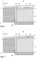
- a mold insert 3 is inserted into a receptacle 4 of an injection mold 5 .
- the mold insert 3 has the surface relief 32 to be molded on its surface 31 facing a cavity 51 of the injection mold in the inserted state. After the injection mold 5 has been closed, the cavity 51 is filled with the casting compound, so that the surface relief 32 is molded in the plastic molded part 1 .
- the surface relief 32 only forms a partial area of the surface 52 of the cavity 51 . In other words, part of the surface 11 of the plastic molding 1 remains smooth.
- the diffractive surface relief 2 can be a computer-generated hologram, a Fourier hologram or a kinoform.
- a floating image of a motif such as a symbol, logo, sign, image or the like can thus be generated in transmitted light.
- the relief preferably has a spatial frequency of between 100 lines/mm and 3000 lines/mm and/or a relief depth of 100 nm to 10 ⁇ m.
- Figures 1 and 2 show different types of attachment of the mold insert 3 in the injection mold 5.
- the mold insert 3 is held non-positively by a stamp 6 on an undercut 53 of a stamp sleeve 60 .
- a step or gap is created between the mold insert 3 between the adjacent surface of the stamp sleeve 60 and the surface relief 32 on the mold insert 3.
- the mold insert 3 is fastened in the stamp sleeve 60 by means of an undercut in a form-fitting manner and advantageously flush with the adjacent surface of the stamp sleeve 60 and is additionally glued to the stamp 6 .
- FIG. 5 shows the punch 6 with the mold insert 3 fastened thereon.
- the punch 6 has a stop 62 on its underside, so that the punch 6 only dips to a desired depth in the punch sleeve 60 and thus the mold insert 3 on the opposite side in the desired manner with the adjacent surface of the punch sleeve 60 works together.
- the stamp sleeve 60 is closed with a cover 61 on the underside, in particular screwed, in order to also fasten the stamp 6 in the stamp sleeve 60 .
- the stamp sleeve 60 is then inserted into the receptacle 4 in the injection mold 5 and is in turn fastened there by means of a screw connection.
- the stamping sleeve 60 also has a stop 63 in order to dip into the receptacle 4 of the injection mold 5 only up to a desired depth and to interact with the adjacent surface of the cavity 51 in the cavity 51 as desired.
- the tolerance or play between the receptacle 4 and the punch sleeve 60 and between the punch sleeve 60 and the punch 6 is preferably about 0.01 mm to 0.05 mm, in particular 0.02 mm to 0.03 mm.
- a flat master is first produced, which includes a layer of resist lacquer.
- a preliminary surface relief 7 is exposed in this layer. This can be done, for example, by means of a laser or electron beam or by exposure to a mask. This allows a detail resolution of about one micrometer to be achieved. Single or multiple exposures are possible, which can result in particular in two-, four- or eight-step surface profiles.
- the resist is then developed so that the preliminary surface relief is formed.
- the resist lacquer is then coated with a conductive lacquer.
- An electrical voltage is applied to the conductive lacquer layer in an electroplating bath and a metal, preferably nickel, is deposited on the master.
- the layer thickness is 0.05 mm to 1 mm.
- the metal body produced in this way now also has the provisional surface relief. Galvanic copies can in turn be made of this metal body.
- this metal body In order to be able to provide arbitrarily shaped plastic moldings 1 with a diffractive surface structure 2, this metal body must now be adapted to the shape of the plastic molding to be produced. How 3 shows, this is done by deep drawing. Here, the metal body is deformed between a stamp 8 and a counter-holder 9 until it has the desired shape. The mold insert 3 obtained in this way can, if necessary, be further cut to size and provided with fastening elements. A material that is softer than the metal body is used for the stamp 8 and counter-holder 9 . If this consists of nickel, deep-drawing tools made of steel are used, for example. As a result, the preliminary surface relief 7 is not damaged.
- curved surfaces with radii of curvature that are at least 100 times and at most 0.1 times, preferably at least 10 times and at most 0.25 times, particularly preferably at least 5 times and at most 0.33 times the lateral extent of the diffractive surface relief.
- the radii of curvature can be in the range from 10000 mm to 10 mm, preferably from 1000 mm to 25 mm, particularly preferably from 500 mm to 33 mm, in particular with a lateral extent of 100 mm.
- drawing depths of 4.8 mm with a thickness of the mold insert 3 of 0.5 mm to 1 mm or drawing depths of 2.4 mm with a thickness of the mold insert 3 of 0.5 mm can be achieved become.
- drawing depths of 10 mm can be achieved with a thickness of the mold insert 3 of 0.5 mm.
- the provisional surface relief 7 is deformed by the deep-drawing and thus changes its optical properties. This must be taken into account when designing the provisional surface relief 7 . For this reason, a preliminary surface relief 7 must be produced, which results in the desired diffractive surface relief 2 after the deformation.
- a function F1 is first determined which reproduces the desired diffractive effect.
- Such functions can, for example, be calculated and represented in the following way:
- the overall hologram is then calculated from the superimposition of all individual holograms.
- the resulting overall phase function is converted into a diffractive phase function for the design wavelength (eg red LED, wavelength 640 nm).
- the diffractive surface relief is then approximately exposed in a photoresist system.
- the "minimum feature size” determines the smallest possible structure sizes and thus the largest possible diffractive diffraction angle or largest possible additional focusing functions.
- a correction function K is also determined, which characterizes the change in the provisional surface relief during the deformation or the optical effect brought about by the deformation.
- a correction function K results in the form of a correspondingly oppositely shaped spherical curvature geometry.
- the correction function K is applied in such a way that a correction phase function that is designed opposite to the curvature geometry of the mold insert 3 is taken into account.
- the correction is particularly simple when the symmetry of the curvature of the mold insert 3 is matched to the symmetry of the motif to be represented by the diffractive surface relief 2 .
- a rotationally symmetrical motif and a correspondingly similar rotationally symmetrical curvature of the mold insert 3 can be superimposed in such a way that the two centers of symmetry lie on top of one another.
- a concrete example is a bulge in the shape of a spherical sector and a motif in the shape of a star.
- the center of the spherical sector and the center of the star preferably lie one above the other.
- distortions of the star due to the additional warping remain optically largely unproblematic and affect or impair the optical effect very little.
- by analyzing the symmetry of the camber and the motif one can find similar solutions where the camber has little disruptive effect on the desired visual effect.
- Critical variables when correcting the distortion are in particular the radius of curvature R of the diffractive surface relief 2, the lateral extent Ld of the diffractive surface relief 2, the lateral extent Li of the intensity pattern projected in transmission and the divergence angle of the light source.
- R of the diffractive surface relief 2 the radius of curvature
- Ld the lateral extent of the diffractive surface relief 2
- Li the lateral extent Li of the intensity pattern projected in transmission
- Li the lateral extent
- a further function F2 which represents the provisional surface relief 7, can be calculated by applying the correction function K to the function F1. If the provisional surface relief 7 calculated in this way is introduced into the metal body, a diffractive surface relief 2 is obtained in the finished mold insert 3 and thus also in the plastic molded part 1, which shows the desired diffractive effect.
- the plastic molded part 1 When calculating the surface reliefs 2 and 7, other parameters that are important for the desired application of the plastic molded part 1 can also be taken into account. If the plastic molded part is to be attached to an illumination device, for example, so that an optically floating symbol is generated in transmitted light, the viewing distance, viewing angle, distance from the light source, divergence angle of the light source and any focusing optics that may still be present are taken into account.
- a dedicated focusing function can also be mathematically integrated into the diffractive surface relief 7 . Particularly good results are achieved by combining the integrated focusing function with partial focusing using external optics.
- the divergence angle (half angle) of the light source should be in the range of 5° to 60°.
- the plastic molded part 1 can be produced by injection molding. If the diffractive effect is to be visible in transmitted light, transparent plastics such as PMMA (transmission 92%), PET-G (transmission 91%), ABS (transmission 85%) or PC (transmission 88%) must be used. However, surface structures that can be viewed in reflected light can also be introduced, which can be used with opaque or semi-transparent plastics or in insert molding processes. It should be noted here that the structure depths of the diffractive surface relief for elements in transmission must be many times greater than for elements that work in reflection.
- transparent plastics such as PMMA (transmission 92%), PET-G (transmission 91%), ABS (transmission 85%) or PC (transmission 88%) must be used.
- surface structures that can be viewed in reflected light can also be introduced, which can be used with opaque or semi-transparent plastics or in insert molding processes. It should be noted here that the structure depths of the diffractive surface relief for elements in transmission must be many times greater than for elements that work
- structural depths of the diffractive surface relief for elements in transmission are approximately 0.5 ⁇ m to 3 ⁇ m and the structural depths of the diffractive surface relief for elements in reflection are approximately 0.1 ⁇ m to 0.5 ⁇ m.
- such opaque plastics can advantageously contain a reflection-increasing layer in order to increase the visibility and brilliance of the optical effect of the diffractive surface relief.
- Insertion of the mold insert 3 does not adversely affect the cycle time of the molding process. This mainly depends on the geometry and size, as well as on the wall thickness of the plastic molded part 1, because the cooling time of the injection molding material is determined by these variables, in particular primarily by the wall thickness.
- the cycle time of the casting process is usually between 5 seconds and 180 seconds, in particular between 10 seconds and 180 seconds.
- the diffractive surface relief 2 is thereby irradiated with light, which by means of a focusing element achieves the desired divergence having.
- Light source 7 and diffractive surface relief 3 are arranged at a distance L.
- the distance L is preferably about 0.5 cm to about 10 cm.
- the light shining through the diffractive surface relief 2 produces an optical effect 73 which can be seen at the viewing distance A with the unaided human eye, ie without further aids.
- the viewing distance A is preferably about 20 cm to 500 cm. However, the effect 73 is also visible outside of this area.
- a quasi-continuous, diffractive phase function is calculated as a computer-generated hologram, which is generated in diffractive relief structures with the smallest local grating periods of approx. 5 ⁇ m to 10 ⁇ m and structure depths of approx. 1 ⁇ m to 1.5 ⁇ m results.
- the diffractive surface relief 2 contains the remaining correction of the beam path of the light necessary for the desired divergence of the light or the desired optical effect, with this correction on the path of the macrostructure (in this example the component curvature is a spherical deformation) is adjusted.
- the in 4 A red LED with a divergence angle (half angle) of 45 degrees is used as the light source 71 for illuminating or backlighting the transparent plastic material of the plastic molding 1 .
- the additional focusing optics 72 is used as a Formed convex lens with a focal length of 40 mm and a diameter of 20 mm.
- the distance between the LED 71 and the focusing optics 72 is 10 mm, the distance between the focusing optics 72 and the diffractive surface relief 2 is approximately 40 mm.
- the surface of the plastic molded part 1 forms a spherical shell with a radius of curvature of 120 mm.
- the diffractive surface relief 3 is circular with a diameter of about 35 mm.
- An optical effect 73 results in the form of a star with a size of approx. 30 mm ⁇ 30 mm, which appears to be approx. 5 cm to 10 cm behind the diffractive surface structure 2 as seen from the viewer.
- the ideal observer distance is approx. 4 m to 5 m in front of the diffractive surface structure 2; the viewer can be positioned slightly offset from the optical axis, e.g. slightly higher or lower.
- a variety of plastic moldings 1 can be produced in the manner described. Since the diffractive surface relief 2 can be arranged on any free-form surface, the design freedom when designing the plastic molded part is not impaired. In particular, diffractive effects can be integrated into existing designs without further changes being necessary.
- the diffractive surface relief 2 occupies only a portion of the surface 11 of the plastic molding 1, other optical or other functions can also be integrated into the plastic molding.
- Possible applications are, for example, lighting devices that project optically floating motifs (apparently lying in front of or behind the plane of the component), backlit switches or controls whose function is indicated by an optically floating symbol, and the like.
Description
Die Erfindung betrifft ein Verfahren zum Herstellen eines Kunststoffformteils.The invention relates to a method for producing a plastic molded part.
Zur Herstellung von optischen Bauteilen aus Kunststoff ist es bekannt, Spritzgussformen zu verwenden.It is known to use injection molds to produce optical components from plastic.
Beispielsweise offenbart die
Aus der
Aus der
Aus der
Es ist die Aufgabe der vorliegenden Erfindung, ein Verfahren bereitzustellen, mittels welchen beliebige Kunststoffformteile durch Spritzgießen mit zusätzlichen optischen Effekten ausgestattet werden können.It is the object of the present invention to provide a method by means of which any desired plastic molded parts can be equipped with additional optical effects by injection molding.
Diese Aufgabe wird durch ein Verfahren mit den Merkmalen des Patentanspruchs 1 gelöst.This object is achieved by a method having the features of patent claim 1.
Bei dem Verfahren zum Herstellen eines Kunststoffformteils wird ein Formeinsatz mit einem diffraktiven Oberflächenrelief bereitgestellt, der Formeinsatz in eine Formhälfte einer Spritzgussform eingesetzt, welche zusammen mit wenigstens einer weiteren Formhälfte eine Kavität zum Herstellen des Kunststoffformteils ausbildet. Der Formeinsatz wird dabei so in die Spritzgussform eingesetzt, dass das diffraktive Oberflächenrelief einen Teilbereich der von der Formhälfte gebildeten Oberfläche der Kavität ausbildet. Anschließend wird das Kunststoffformteil durch Spritzgießen mittels der Spritzgussform abgeformt.In the method for producing a plastic molded part, a mold insert with a diffractive surface relief is provided, the mold insert is inserted into one mold half of an injection mold which, together with at least one other mold half, forms a cavity for producing the plastic molded part. The mold insert is inserted into the injection mold in such a way that the diffractive surface relief forms a partial area of the cavity surface formed by the mold half. The plastic molded part is then molded by injection molding using the injection mold.
Spritzgussformen umfassen in der Regel zwei Formhälften, die zusammen die Kavität ausbilden. Es sind jedoch auch mehrteilige Formen denkbar. Auch bei Formen mit mehr als zwei Teilen, die zusammen die Kavität ausbilden, werden hier die jeweiligen Teile als Formhälften bezeichnet.Injection molds usually include two mold halves that together form the cavity. However, multi-part forms are also conceivable. Even in the case of molds with more than two parts that together form the cavity, the respective parts are referred to here as mold halves.
Unter der Kavität der Spritzgussform wird hier derjenige Hohlraum der Spritzgussform verstanden, der komplementär zum herzustellenden Formteil ist und in dem das Kunststoffformteil abgeformt wird. Weitere Hohlräume der Spritzgussform, wie beispielsweise das Angusssystem werden hier nicht als Bestandteil der Kavität verstanden.The cavity of the injection mold is understood here as that cavity of the injection mold which is complementary to the molded part to be produced and in which the plastic molded part is molded. Other cavities in the injection mold, such as the gating system, are not understood here as part of the cavity.
Der Formeinsatz umfasst ein diffraktives Oberflächenrelief und ist so in eine Formhälfte einer Spritzgussform, welche zusammen mit wenigstens einer weiteren Formhälfte eine Kavität zum Herstellen des Kunststoffformteils ausbildet, derart einsetzbar, dass das diffraktive Oberflächenrelief einen Teilbereich der von der Formhälfte gebildeten Oberfläche der Kavität der Spritzgussform ausbildet.The mold insert comprises a diffractive surface relief and can thus be inserted into a mold half of an injection mold, which together with at least one other mold half forms a cavity for producing the plastic molded part, in such a way that the diffractive surface relief forms a partial area of the surface of the cavity of the injection mold formed by the mold half .
Die Spritzgussform zum Herstellen eines Kunststoffformteils umfasst zumindest eine Formhälfte, welche zusammen mit wenigstens einer weiteren Formhälfte eine Kavität zum Herstellen des Kunststoffformteils ausbildet, wobei die Formhälfte eine Aufnahme aufweist, in welche ein Formeinsatz mit einem diffraktiven Oberflächenrelief so einsetzbar ist, dass das diffraktive Oberflächenrelief einen Teilbereich der von der Formhälfte gebildeten inneren Oberfläche der Kavität der Spritzgussform ausbildet.The injection mold for producing a plastic molding comprises at least one mold half which, together with at least one other mold half, forms a cavity for producing the plastic molding, the mold half having a receptacle into which a mold insert with a diffractive surface relief can be inserted in such a way that the diffractive surface relief has a Forms part of the inner surface formed by the mold half of the cavity of the injection mold.
Ein mittels des beschriebenen Verfahrens unter Verwendung der beschriebenen Spritzgussform und des beschriebenen Formeinsatzes hergestelltes Kunststoffformteil umfasst ein diffraktives Oberflächenrelief, welches sich über lediglich einen Teilbereich einer Oberfläche des Kunststoffformteils erstreckt.A plastic molded part produced by means of the described method using the described injection mold and the described mold insert comprises a diffractive surface relief which extends over only a partial area of a surface of the plastic molded part.
Auf die beschriebene Art und Weise können Kunststoffformteile erhalten werden, die diffraktive optische Elemente umfassen, jedoch nicht notwendigerweise als optische Bauelemente konzipiert sind. Die nicht durch das diffraktive Oberflächenrelief belegten Teilbereiche der Oberfläche können also weitere Funktionen übernehmen. Das diffraktive Oberflächenrelief kann damit beispielsweise auch lediglich zu dekorativen Zwecken, zu Zwecken der Fälschungssicherheit oder als Beschriftung dienen. Ferner stehen die nicht durch das diffraktive Oberflächenrelief belegten Teilbereiche der Oberfläche somit auch für andere optische Funktionen zur Verfügung. So kann beispielsweise ein dekoratives diffraktives Element mit anderen, nicht-diffraktiven Elementen, wie z.B. Retroreflektoren oder dergleichen, kombiniert werden. Es ist ebenso möglich, die nicht durch das diffraktive Oberflächenrelief belegten Teilbereiche der Oberfläche während des Spritzgussvorgangs beispielsweise mit IMD-Folien oder IML-Etiketten (IMD = In Mould Decoration; IML = In Mould Labelling) zu dekorieren oder in einem nachfolgenden Prozessschritt anderweitig zu dekorieren und/oder mit weiteren funktionellen Beschichtungen zu versehen. Ebenso können die nicht durch das diffraktive Oberflächenrelief belegten Teilbereiche der Oberfläche in einem Mehrkomponenten-Spritzguss auch aus einem anderen Spritzgussmaterial, welches insbesondere nicht transparent ist, ausgebildet sein. Ebenso ist es möglich, dass die nicht durch das diffraktive Oberflächenrelief belegten Teilbereiche der Oberfläche hochglänzend und glatt und dadurch bevorzugt hochtransparent und klar durchsichtig sind.In the manner described, molded plastic parts can be obtained which include diffractive optical elements, but are not necessarily designed as optical components. The partial areas of the surface that are not occupied by the diffractive surface relief can therefore take on additional functions. The diffractive surface relief can thus also serve, for example, merely for decorative purposes, for purposes of counterfeit security or as inscription. Furthermore, the partial areas of the surface not occupied by the diffractive surface relief are therefore also available for other optical functions. For example, a decorative diffractive element can be combined with other non-diffractive elements such as retroreflectors or the like. It is also possible to decorate the sub-areas of the surface that are not covered by the diffractive surface relief during the injection molding process, for example with IMD foils or IML labels (IMD = In Mold Decoration; IML = In Mold Labelling) or in a subsequent process step otherwise to decorate and / or to provide other functional coatings. Likewise, the partial areas of the surface that are not occupied by the diffractive surface relief can also be formed in a multi-component injection molding process from another injection molding material, which in particular is not transparent. It is also possible for the partial areas of the surface not covered by the diffractive surface relief to be highly glossy and smooth and therefore preferably highly transparent and clear.
Die mit dem diffraktiven Oberflächenrelief belegten Teilbereiche der Oberfläche sind durch das Oberflächenrelief nicht glatt oder hochglänzend und bilden daher einen optischen Kontrast zu beispielsweise benachbarten hochglänzend, glatten Oberflächen. Dieser Kontrast kann in manchen praktischen Fällen gewünscht sein, in anderen unerwünscht. Der Kontrast lässt sich im unerwünschten Fall beispielsweise durch Übergangsbereiche zwischen dem diffraktiven Oberflächenrelief und den benachbarten hochglänzenden, glatten Oberflächen etwas kaschieren, wobei die Übergangsbereiche geringfügig strukturiert sind und/oder eine sich abschwächende Strukturierung mit einer Abschwächung zu der hochglänzenden, glatten Oberfläche hin aufweist.The partial areas of the surface covered with the diffractive surface relief are not smooth or high-gloss due to the surface relief and therefore form an optical contrast to, for example, neighboring high-gloss, smooth surfaces. This contrast may be desirable in some practical cases and undesirable in others. In the undesired case, the contrast can be somewhat concealed, for example, by transition areas between the diffractive surface relief and the adjacent high-gloss, smooth surfaces, the transition areas being slightly structured and/or having a weakening structure with a weakening towards the high-gloss, smooth surface.
Vorzugsweise wird als Formeinsatz ein Formeinsatz bereitgestellt, dessen diffraktives Oberflächenrelief durch eine additive oder subtraktive Überlagerung einer diffraktiven Mikrostruktur und einer insbesondere gekrümmten Makrostruktur ausgebildet wird. Die Makrostruktur kann dabei als makroskopische Krümmung bzw. allgemein als beliebig ausgeformte Freiformfläche ausgebildet sein, auf der die diffraktive Mikrostruktur angeordnet ist.A mold insert is preferably provided as a mold insert, the diffractive surface relief of which is formed by an additive or subtractive superimposition of a diffractive microstructure and an in particular curved macrostructure. The macrostructure can be designed as a macroscopic curvature or generally as a free-form surface of any shape, on which the diffractive microstructure is arranged.
Die Makrostruktur entspricht vorzugsweise der durch die gegenüberliegende Oberfläche des Kunststoffformteils definierten Oberflächenstruktur. Vorzugsweise ist die Makrostruktur so gewählt, dass der Abstand zwischen der durch die Makrostruktur definierten fiktiven makroskopischen Oberfläche des Kunststoffformteils und der gegenüberliegenden Oberfläche des Spritzgussformteils zumindest in einem nicht-ebenen Bereich des diffraktiven Oberflächenreliefs im Wesentlichen konstant ist, und vorzugsweise um nicht mehr als ±20%, weiter bevorzugt sich um nicht mehr als ±10% variiert. Beispielsweise variiert so die Wandstärke bei einem 2 mm bis 3 mm dicken Bauteil um nicht mehr als 0,4 mm. Damit wird eine weitgehend konstante Wanddicke des Spritzgussformteils erreicht, wodurch eine ausreichend gute Stabilität in allen Bereichen erreicht werden kann. Es entstehen dabei also keine Schwachstellen oder Sollbruchstellen. Dementsprechend sind auch die gegenüberliegenden Wandflächen der Kavität der Spritzgussform zumindest im Bereich des Formeinsatzes im Wesentlichen konstant beabstandet, so dass das Kunststoffformteil mittels des beschriebenen Verfahrens gefertigt werden kann.The macrostructure preferably corresponds to the surface structure defined by the opposite surface of the plastic molding. Preferably, the macrostructure is chosen such that the distance between the notional macroscopic surface of the plastic molding defined by the macrostructure and the opposite surface of the injection molded part is substantially constant, at least in a non-planar area of the diffractive surface relief, and preferably by no more than ±20 %, further preferably does not vary by more than ±10%. For example, the wall thickness of a 2 mm to 3 mm thick component does not vary by more than 0.4 mm. This achieves a largely constant wall thickness of the injection molded part, as a result of which sufficiently good stability can be achieved in all areas. There are no weak points or predetermined breaking points. Accordingly, the opposite wall surfaces of the cavity of the injection mold are also spaced apart essentially constantly, at least in the area of the mold insert, so that the plastic molded part can be manufactured using the method described.
Die diffraktive Mikrostruktur kann damit in beliebig geformte Oberflächen integriert werden. Insbesondere ist es damit möglich, eine diffraktive Struktur in ein bestehendes Bauteil einzubringen, ohne dass dessen Form angepasst bzw. speziell verändert werden muss. Ein besonderer Vorteil liegt darin, dass im Gegensatz zu bekannten Verfahren und Spritzgussformen hier ermöglicht wird, die diffraktive Mikrostruktur in gekrümmte Flächen einzubringen. Es muss also kein flacher bzw. ebener Bereich bereitgestellt werden, wenn eine diffraktive Mikrostruktur in ein Bauteil integriert werden soll. Die Designfreiheit bei der Entwicklung von Kunststoffformteilen mit diffraktiven Oberflächenreliefs wird also nicht eingeschränkt.The diffractive microstructure can thus be integrated into surfaces of any shape. In particular, it is thus possible to introduce a diffractive structure into an existing component without its shape having to be adapted or specially modified. A particular advantage is that, in contrast to known methods and injection molds, it is possible here to introduce the diffractive microstructure into curved surfaces. It is therefore not necessary to provide a flat or planar area if a diffractive microstructure is to be integrated into a component. The freedom of design in the development of plastic molded parts with diffractive surface reliefs is therefore not restricted.
Auch größere Änderungen an bestehenden Spritzgusswerkzeugen sind nicht notwendig, lediglich der entsprechende Formeinsatz muss vorgesehen und eingesetzt werden. Dies ermöglicht eine besonders hohe Planungsflexibilität und geringe Umstellungskosten, wenn ein bestehendes Bauteil zukünftig mit einer diffraktiven Mikrostruktur versehen werden soll.Even major changes to existing injection molding tools are not necessary, only the appropriate mold insert has to be provided and used. This enables a particularly high level of planning flexibility and low conversion costs if an existing component is to be provided with a diffractive microstructure in the future.
Unter Mikrostrukturen werden hier vorzugsweise Strukturen verstanden, deren Strukturelemente und/oder lokale Minima oder Maxima eine mittlere Beabstandung von weniger als 500 µm, bevorzugt von weniger als 100 µm, weiter bevorzugt von weniger als 10 µm aufweisen.Microstructures here are preferably structures whose structural elements and/or local minima or maxima have an average spacing of less than 500 μm, preferably less than 100 μm, more preferably less than 10 μm.
Eine diffraktive Mikrostruktur weist vorzugsweise eine Spatialfrequenz von mehr als 100 Linien/mm, vorzugsweise mehr als 300 Linien/mm, weiter bevorzugt zwischen 800 Linien/mm bis 2800 Linien/mm auf. Die Relieftiefe der diffraktiven Mikrostruktur beträgt vorzugsweise zwischen 50 nm und 100 µm, weiter bevorzugt zwischen 200 nm und 10 µm.A diffractive microstructure preferably has a spatial frequency of more than 100 lines/mm, preferably more than 300 lines/mm, more preferably between 800 lines/mm to 2800 lines/mm. The relief depth of the diffractive microstructure is preferably between 50 nm and 100 μm, more preferably between 200 nm and 10 μm.
Bei der diffraktiven Mikrostruktur handelt es sich vorzugsweise um ein 2D/3D Hologramm, ein Kinoform, ein Fourier-Hologramm, ein speziell entsprechend der optischen Funktion berechnetes computergeneriertes Hologramm (CGH = Computer Generated Hologram), oder ein KINEGRAM® ,oder TRUSTSEAL® bestehend aus ein- oder zweidimensionalen periodischen Beugungsgittern, isotropen oder anisotropen Mattstrukturen (mit einer statistischen Variation der Strukturparameter), asymmetrischen Blazegitter mit kontinuierlicher oder stufenartiger Phasenfunktion (insbesondere 2, 4 oder 8 Stufen), um linsenartige Strukturen, oder um eine Kombinationsstruktur mit ein oder mehreren der vorgenannten Strukturen.The diffractive microstructure is preferably a 2D/3D hologram, a kinoform, a Fourier hologram, a computer-generated hologram (CGH = Computer Generated Hologram) specially calculated according to the optical function, or a KINEGRAM ® , or TRUSTSEAL ® consisting of one- or two-dimensional periodic diffraction gratings, isotropic or anisotropic matte structures (with a statistical variation of the structure parameters), asymmetric blaze gratings with a continuous or step-like phase function (in particular 2, 4 or 8 steps), around lens-like structures, or around a combination structure with one or more of the aforementioned structures.
Die Mikrostruktur ist bzgl. ihrer Reliefparameter, insbesondere Spatialfrequenz und Relieftiefe, vorzugsweise so ausgelegt, dass in Auflichtbetrachtung und/oder Durchlichtbetrachtung ein optisch variabler Effekt generiert wird, welcher für den menschlichen Betrachter, ggf. unter Zuhilfenahme einer speziellen Lichtquelle (LED, Laserpointer, Punktlichtquelle in einer vorgegebenen Beabstandung usw.) sichtbar wird, wenn die Mikrostruktur in ein vorzugsweise transparentes Kunststoffmaterial mit vorzugsweise einem Brechungsindex von etwa 1,5 bis 1,6 abgeformt wird.With regard to its relief parameters, in particular spatial frequency and relief depth, the microstructure is preferably designed in such a way that an optically variable effect is generated when viewed in incident light and/or viewed through transmitted light, which is visible to the human observer, if necessary with the aid of a special light source (LED, laser pointer, point light source at a predetermined spacing, etc.) becomes visible when the microstructure is molded into a preferably transparent plastics material, preferably having a refractive index of about 1.5 to 1.6.
Unter Makrostrukturen werden vorzugsweise Strukturen verstanden, deren Strukturelement und/oder lokale Minima oder Maxima mehr als 10 µm, vorzugsweise mehr als 50 µm, weiter bevorzugt zwischen 100 µm und 500 µm voneinander beabstandet sind. Die Relieftiefe der Makrostrukturen beträgt vorzugsweise mehr als 0,5 µm, weiter bevorzugt mehr als 5 µm.Macrostructures are preferably understood to mean structures whose structural elements and/or local minima or maxima are spaced apart from one another by more than 10 μm, preferably more than 50 μm, more preferably between 100 μm and 500 μm. The relief depth of the macrostructures is preferably more than 0.5 μm, more preferably more than 5 μm.
Es ist weiter zweckmäßig, wenn als Formeinsatz ein Formeinsatz bereitgestellt wird, dessen Makrostruktur eine zumindest bereichsweise gekrümmte Freiformfläche mit ein oder mehreren Krümmungen beschreibt, wobei die ein oder mehreren Krümmungen jeweils einen Krümmungsradius aufweisen, der mindestens das 100-fache und höchstens das 0,1-fache, bevorzugt mindestens das 10-fache und höchstens das 0,25-fache, besonders bevorzugt mindestens das 5-fache und höchstens das 0,33-fache der lateralen Ausdehnung des diffraktiven Oberflächenreliefs beträgt, und/oder die ein oder mehreren Krümmungen jeweils einen Krümmungsradius im Bereich von 10000 mm bis 10 mm, bevorzugt von 1000 mm bis 25 mm, besonders bevorzugt von 500 mm bis 33 mm aufweisen, insbesondere bei einer lateralen Ausdehnung von 100 mm. Größere Krümmungsradien, also flachere Freiformflächen, sind jedoch auch möglich. Die lokalen makroskopischen Krümmungen des diffraktiven Oberflächenreliefs sind im Wesentlichen durch die Außenform des Bauteils vorgegeben, abgeleitet aus der Forderung nach einer konstanten Wandstärke des Bauteils.It is also expedient if a mold insert is provided as the mold insert, the macrostructure of which describes an at least partially curved free-form surface with one or more curvatures, the one or more curvatures each having a radius of curvature that is at least 100 times and at most 0.1 times, preferably at least 10 times and is at most 0.25 times, particularly preferably at least 5 times and at most 0.33 times the lateral extent of the diffractive surface relief, and/or the one or more curvatures each have a radius of curvature in the range from 10000 mm to 10 mm , preferably from 1000 mm to 25 mm, particularly preferably from 500 mm to 33 mm, in particular with a lateral extent of 100 mm. However, larger radii of curvature, ie flatter free-form surfaces, are also possible. The local macroscopic curvatures of the diffractive surface relief are essentially determined by the external shape of the component, derived from the requirement for a constant wall thickness of the component.
Unter der lateralen Ausdehnung des diffraktiven Oberflächenreliefs wird dabei der größte Abstand zwischen zwei auf der Randkurve des Oberflächenreliefs liegenden Punkten verstanden, also beispielsweise der Durchmesser bei einem kreisförmigen Oberflächenrelief oder die Länge der Diagonale bei einem rechteckigen Oberflächenrelief. Neben einer Kreisform oder einem Rechteck sind auch jegliche anders geformte Konturen des Oberflächenreliefs möglich, um insbesondere eine gestalterisch ansprechende Integration des Oberflächenreliefs in das Bauteil zu ermöglichen. Beispielsweise kann die Kontur des Oberflächenreliefs ein Vieleck oder ein Polygon sein oder bereichsweise durch stetige konvexe und/oder konkave Kurven, insbesondere mittels mathematischer Funktionsverläufe begrenzt sein.The lateral extent of the diffractive surface relief is understood to be the greatest distance between two points lying on the edge curve of the surface relief, ie, for example, the diameter in the case of a circular surface relief or the length of the diagonal in the case of a rectangular surface relief. In addition to a circular shape or a rectangle, any differently shaped contours of the surface relief are also possible, in order in particular to enable the surface relief to be integrated into the component in a way that is appealing in terms of design. For example, the contour of the surface relief can be a polygon or can be delimited in some areas by constant convex and/or concave curves, in particular by means of mathematical function curves.
Bei derartigen vorgenannten Krümmungsradien kann die diffraktive Mikrostruktur problemlos mit der Makrostruktur überlagert werden, ohne dass es zu nicht korrigierbaren Verzerrungen des gewünschten diffraktiven Effekts kommt.With such aforesaid radii of curvature, the diffractive microstructure can be superimposed with the macrostructure without any problems, without the desired diffractive effect being distorted in a way that cannot be corrected.
Erfindungsgemäß wird beim Bereitstellen des Formeinsatzes zunächst ein vorläufiges diffraktives Oberflächenrelief in einer Oberfläche eines Substrats ausgebildet, insbesondere in ein flaches Metallteil, und anschließend das Substrat zur Ausbildung des Formeinsatzes umgeformt, wobei beim Umformen das vorläufige Oberflächenrelief in das diffraktive Oberflächenrelief des Formeinsatzes verformt wird.According to the invention, when the mold insert is provided, first a preliminary diffractive surface relief is formed in a surface of a substrate, in particular in a flat metal part, and then the substrate is formed to form the mold insert, with the preliminary surface relief being deformed into the diffractive surface relief of the mold insert during the forming process.
Somit können bekannte Verfahren zum Einbringen von Oberflächenreliefs in flache Bauteile angewendet werden, ohne dass sie für gekrümmte Oberflächen angepasst werden müssen.Known methods for introducing surface reliefs into flat components can thus be used without having to be adapted for curved surfaces.
Das Umformen des Substrats erfolgt dabei vorzugsweise durch Tiefziehen. Dabei ist es zweckmäßig, wenn zum Tiefziehen ein Werkzeug verwendet wird, dessen Härte geringer ist als eine Härte des Werkstoffes des Substrats. Hierdurch wird sichergestellt, dass die diffraktive Mikrostruktur durch das Tiefziehwerkzeug nicht beschädigt wird.The substrate is preferably formed by deep drawing. It is expedient here if a tool is used for the deep-drawing, the hardness of which is less than the hardness of the material of the substrate. This ensures that the diffractive microstructure is not damaged by the deep-drawing tool.
Es ist vorteilhaft, wenn zum Ausbilden des vorläufigen Oberflächenreliefs zunächst ein Masterelement, insbesondere umfassend einen Resistlack, bereitgestellt wird, in welches das vorläufige Oberflächenrelief eingeformt wird und anschließend das Substrat von dem Masterelement abgeformt wird.It is advantageous if, in order to form the provisional surface relief, first a master element, in particular comprising a resist, is provided, into which the provisional surface relief is formed and then the substrate is molded from the master element.
Sobald ein solches Masterelement bereitgestellt ist, können also auf einfache Weise eine Mehrzahl von Substraten als Kopien des Masterelements hergestellt werden. Dies vereinfacht die Herstellung verglichen mit dem direkten Einbringen des vorläufigen Oberflächenreliefs in jedes einzelne Substrat. Insbesondere ist das direkte Einbringen von Mikrostrukturen in Resistlacke deutlich einfacher als das direkte Einbringen von Mikrostrukturen in metallische Substrate.As soon as such a master element is provided, a plurality of substrates can thus be produced as copies of the master element in a simple manner. This simplifies the production compared to the direct incorporation of the preliminary surface relief into each individual substrate. In particular, the direct incorporation of microstructures in resists is significantly easier than the direct incorporation of microstructures in metallic substrates.
Bevorzugt wird das vorläufige Oberflächenrelief durch Lithographieverfahren, wie Laserstrahllithographie oder Elektronenstrahllithographie oder durch Belichtung mittels einer Maske und UV-Belichtung in das Masterelement und/oder in das Substrat, in der Regel eine strahlungssensitive Resistlackschicht eingebracht (in diesem Fall durch Belichten und anschließendes Entwickeln). Dies ermöglicht ein besonders schnelles und flexibles Einformen des vorläufigen Oberflächenreliefs.The preliminary surface relief is preferably introduced by lithography methods such as laser beam lithography or electron beam lithography or by exposure using a mask and UV exposure in the master element and/or in the substrate, usually a radiation-sensitive resist layer (in this case by exposure and subsequent development). This enables the provisional surface relief to be molded in particularly quickly and flexibly.
Vorzugsweise wird das vorläufige Oberflächenrelief als computergeneriertes Hologramm (speziell berechnet) und/oder als Kinoform (speziell berechnet) und/oder als Fourierhologramm (holographisch aufgezeichnet) in das Masterelement und/oder das Substrat eingebracht.The preliminary surface relief is preferably introduced into the master element and/or the substrate as a computer-generated hologram (specifically calculated) and/or as a kinoform (specifically calculated) and/or as a Fourier hologram (holographically recorded).
Nach dem Einformen des vorläufigen Oberflächenreliefs wird das Substrat bevorzugt durch galvanisches Abscheiden eines Metalls, insbesondere von Nickel, auf das Masterelement erzeugt. Hierdurch kann das vorläufige Oberflächenrelief mit hoher Qualität vom Masterelement auf das härtere Metallsubstrat übertragen werden. Zweckmäßigerweise wird dazu das Masterelement zunächst leitfähig gemacht, beispielsweise durch Auftragen eines leitfähigen Lacks. Anschließend kann das Metall durch Anlegen einer Spannung an das so beschichtete Masterelement in einem Galvanisierungsbad abgeschieden werden.After the provisional surface relief has been formed, the substrate is preferably produced by galvanically depositing a metal, in particular nickel, onto the master element. As a result, the provisional surface relief can be transferred from the master element to the harder metal substrate with high quality. For this purpose, the master element is expediently first made conductive, for example by applying a conductive lacquer. The metal can then be deposited in an electroplating bath by applying a voltage to the master element coated in this way.
Die Schichtdicke des so abgeschiedenen Substrats beträgt dabei vorzugsweise 0,05 mm bis 1 mm. Solche Substrate sind einerseits haltbar genug, um in Formeinsätzen zum Spritzgießen verwendet werden zu können, andererseits aber auch dünn genug, um problemlos durch Tiefziehen umgeformt zu werden.The layer thickness of the substrate deposited in this way is preferably 0.05 mm to 1 mm. Such substrates are strong enough to be used in mold inserts for injection molding, yet thin enough to be easily thermoformed.
Bevorzugt wird zum Einformen des vorläufigen Oberflächenreliefs eine Korrekturfunktion K ermittelt und zur Bestimmung einer das vorläufige Oberflächenrelief beschreibenden Funktion F2 auf eine die zu erzielenden diffraktiven Effekte beschreibende Funktion F1 angewendet.A correction function K is preferably determined for shaping the preliminary surface relief and applied to a function F1 describing the diffractive effects to be achieved in order to determine a function F2 describing the preliminary surface relief.
So ist es beispielsweise möglich, dass die Korrekturfunktion K die Veränderung bzw. die Verzerrung des vorläufigen Oberflächenreliefs bei der Verformung charakterisiert und beispielsweise so das makroskopische Oberflächenprofil definiert, welches durch die Verformung bei Verformung eines ebenen Oberflächenprofils bewirkt wird.It is thus possible, for example, for the correction function K to characterize the change or the distortion of the provisional surface relief during the deformation and, for example, to define the macroscopic surface profile which is brought about by the deformation when a planar surface profile is deformed.
Aus der die zu erzielenden diffraktiven Effekten beschreibenden Funktion F1 kann damit zum Einen zunächst die hierzu abzuformende Mikrostruktur M bestimmt werden und im Weiteren diese Mikrostruktur gemäß der Korrekturfunktion K so vorverzerrt werden, dass die durch die Umformung bewirkte Verformung wieder ausgeglichen wird.From the function F1 describing the diffractive effects to be achieved, the microstructure M to be molded for this purpose can first be determined and then this microstructure can be predistorted according to the correction function K such that the deformation caused by the deformation is compensated for again.
Beschreibt so beispielsweise die Korrekturfunktion K die durch die Verformung bewirkte Veränderung einer ebenen Oberfläche mittels einer entsprechenden Verzerrungsmatrix, so kann F2 beispielsweise wie folgt bestimmt werden: ![]()
![]()
Weiter kann hierzu beispielsweise die ermittelte Mikrostruktur M mit einer Makrostruktur (multiplikativ) überlagert werden, die durch die invertierte Korrekturfunktion beschrieben wird und die beispielsweise die inverse Ausformung zu der von der Verformung bewirkten Verformung einer glatten Fläche (Makrostruktur) darstellt.Furthermore, for example, the determined microstructure M can be overlaid with a macrostructure (multiplicative), which is described by the inverted correction function and which represents, for example, the inverse shape of the deformation of a smooth surface (macrostructure) caused by the deformation.
Vorzugsweise ist es weiter möglich, dass eine Korrekturfunktion K ermittelt wird, welche die durch die Verformung bewirkten optischen Effekte beschreibt, bzw. eine optische Funktion spezifiziert, welche notwendig ist, um die durch die Verformung bewirkten optischen Effekte zumindest teilweise auszugleichen. Wird so beispielsweise durch das Umformen das Substrat kugelförmig verformt, so kann die Korrekturfunktion K beispielsweise die optische Funktion einer entsprechenden Kugellinse bzw. invertierten Kugellinse beschreiben.It is preferably also possible for a correction function K to be determined which describes the optical effects caused by the deformation or specifies an optical function which is necessary in order to at least partially compensate for the optical effects caused by the deformation. If, for example, the substrate is spherically deformed as a result of the reshaping, the correction function K can, for example, describe the optical function of a corresponding spherical lens or inverted spherical lens.
Es ist so zweckmäßig, wenn die Korrekturfunktion K die Veränderung der diffraktiven Effekte des vorläufigen Oberflächenreliefs durch die spätere Verformung des vorläufigen Oberflächenreliefs durch das Umformen beschreibt bzw. zumindest teilweise ausgleicht.It is expedient if the correction function K describes or at least partially compensates for the change in the diffractive effects of the provisional surface relief due to the later deformation of the provisional surface relief by the reshaping.
Diese Korrekturfunktion K wird vorzugsweise auf die hier zu erzielenden diffraktiven Effekte beschreibende Funktion F1 derart angewendet, dass die diffraktiven Effekte berechnet werden, welche bei Berücksichtigung der durch die Korrekturfunktion K beschriebenen optischen Effekte die gemäß F1 zu erzielenden diffraktiven Effekte erzielt und sodann hieraus das vorläufige Oberflächenrelief ermittelt wird.This correction function K is preferably applied to the function F1 describing the diffractive effects to be achieved here in such a way that the diffractive effects are calculated which, taking into account the optical effects described by the correction function K, achieve the diffractive effects to be achieved according to F1 and then from this the preliminary surface relief is determined.
Dies kann beispielsweise bei holographischer Generierung des vorläufigen Oberflächenreliefs dadurch realisiert werden, dass eine entsprechende Linse/Linsensystem, welches die optische Funktion der Korrekturfunktion erbringt, in den Objektstrahl oder Referenzstrahl eingebracht wird.This can be realized, for example, in holographic generation of the preliminary surface relief that a corresponding Lens/lens system, which provides the optical function of the correction function, is introduced into the object beam or reference beam.
Die Funktion F1 beschreibt also, welcher optische Effekt im fertigen Kunststoffformteil auftreten soll. Würde auf der Basis der Funktion F1 die vorläufige Oberflächenstruktur in das Substrat eingeformt, so würde aufgrund der Verformung der vorläufigen Oberflächenstruktur beim Tiefziehen im fertigen Kunststoffformteil ggf. nicht der gewünschte optische Effekt erzielt, sondern beispielsweise ein verzerrtes Hologramm dargestellt. Durch die Anwendung der Korrekturfunktion K auf die Funktion F1 wird dies vermieden. Die erhaltene Funktion F2 beschreibt somit, welche vorläufige Oberflächenstruktur in das Substrat eingebracht werden muss, um nach der Verformung eine diffraktive Oberflächenstruktur zu erhalten, die den gewünschten Effekt erzeugt.The function F1 thus describes which optical effect should occur in the finished plastic molded part. If the preliminary surface structure were formed into the substrate on the basis of function F1, the desired optical effect might not be achieved due to the deformation of the preliminary surface structure during deep-drawing in the finished plastic molded part, but instead a distorted hologram would be displayed. This is avoided by applying the correction function K to the function F1. The function F2 obtained thus describes which preliminary surface structure must be introduced into the substrate in order to obtain a diffractive surface structure after the deformation that produces the desired effect.
Es ist weiter vorteilhaft, wenn der Formeinsatz mittels eines Klemmelements in der Spritzgussform befestigt wird. Auf diese Weise wird ein sicherer Halt des Formeinsatzes während des Spritzgießens sichergestellt. Der Formeinsatz wird dabei bevorzugt durch das Klemmelement allseitig umgriffen und insbesondere kraftschlüssig und/oder formschlüssig gehalten.It is also advantageous if the mold insert is fixed in the injection mold by means of a clamping element. In this way, a secure hold of the mold insert is ensured during injection molding. The mold insert is preferably encompassed on all sides by the clamping element and in particular held in a force-fitting and/or form-fitting manner.
Es ist ferner zweckmäßig, wenn der Formeinsatz an einem Hinterschnitt der Spritzgussform gehalten wird. Auch so ergibt sich eine kraftschlüssige und/oder formschlüssige Befestigung, die zudem den Vorteil mit sich bringen kann, dass der Formeinsatz bündig mit der Oberfläche der Kavität abschließt, so dass sich kein Absatz am fertigen Kunststoffformteil ergibt.It is also expedient if the mold insert is held on an undercut of the injection mold. This also results in a non-positive and/or form-fitting fastening, which can also have the advantage that the mold insert is flush with the surface of the cavity, so that there is no shoulder on the finished plastic molded part.
Zusätzlich oder alternativ kann der Formeinsatz auch mit der Spritzgussform verklebt werden, um einen besonders sicheren Halt zu gewährleisten.Additionally or alternatively, the mold insert can also be glued to the injection mold in order to ensure a particularly secure hold.
Zur Befestigung des Formeinsatzes ist dabei vorzugsweise eine entsprechende Aufnahme in der Spritzgussform vorgesehen. Es ist dabei zweckmäßig, wenn in dieser Aufnahme zumindest ein Stempel vorgesehen ist, mittels welchem bei eingesetztem Formeinsatz ein vorgegebener Anpressdruck auf die der Kavität abgewandte Seite des Formeinsatzes ausübbar ist. Hierdurch wird verhindert, dass sich der Formeinsatz während des Spritzgießens durchbiegt, was zu einer Verformung des Oberflächenreliefs und damit zum Verlust der gewünschten optischen Eigenschaften des Kunststoffformteils führen würde.A corresponding receptacle in the injection mold is preferably provided for fastening the mold insert. It is expedient if at least one stamp is provided in this receptacle, by means of which a predetermined contact pressure is applied to the cavity when the mold insert is inserted side facing away from the mold insert can be exercised. This prevents the mold insert from bending during injection molding, which would lead to a deformation of the surface relief and thus to the loss of the desired optical properties of the plastic molded part.
Es ist weiter zweckmäßig, wenn der Formeinsatz zumindest eine Markierung umfasst, anhand derer die korrekte Orientierung des Formeinsatzes erkennbar ist, wenn dieser in der Spritzgussform eingesetzt ist. Die Orientierung des Formeinsatzes bestimmt auch die Orientierung des gewünschten optischen Effekts. Je nach Art des optischen Effekts kann die korrekte Orientierung bzw. Ausrichtung von Wichtigkeit sein. Für bestimmte optische Effekte kann die Orientierung allerdings auch beliebig sein.It is also expedient if the mold insert has at least one marking that can be used to identify the correct orientation of the mold insert when it is inserted in the injection mold. The orientation of the mold insert also determines the orientation of the desired optical effect. Depending on the type of optical effect, the correct orientation or alignment can be important. For certain optical effects, however, the orientation can also be arbitrary.
Alternativ zur direkten Montage des Formeinsatzes in der Spritzgussform kann auch eine Haltevorrichtung für den Formeinsatz vorgesehen sein, welche so in eine Formhälfte einer Spritzgussform, welche zusammen mit wenigstens einer weiteren Formhälfte eine Kavität zum Herstellen des Kunststoffformteils ausbildet, einsetzbar ist, dass das diffraktive Oberflächenrelief eines in der Haltevorrichtung gehaltenen Formeinsatzes einen Teilbereich der von der Formhälfte gebildeten Oberfläche der Kavität der Spritzgussform ausbildet, wobei die Haltevorrichtung einen insbesondere zylindrischen Grundkörper umfasst, in welchen der Formeinsatz eingesetzt ist. Dies vereinfacht die Handhabung des Formeinsatzes und schützt ihn vor Beschädigungen, da er insbesondere bei der Montage nicht mehr direkt berührt werden muss.As an alternative to the direct installation of the mold insert in the injection mold, a holding device for the mold insert can also be provided, which can be inserted into a mold half of an injection mold, which together with at least one other mold half forms a cavity for producing the plastic molded part, that the diffractive surface relief of a the mold insert held in the holding device forms a partial area of the surface of the cavity of the injection mold formed by the mold half, the holding device comprising a particularly cylindrical base body in which the mold insert is inserted. This simplifies the handling of the mold insert and protects it from damage, since it no longer has to be touched directly during assembly.
Vorzugsweise weist der Grundkörper zumindest einen Hinterschnitt zum Halten des Formeinsatzes und/oder zumindest einen Klebeflansch zum Verkleben des Formeinsatzes mit der Spritzgussform auf. Alternativ oder zusätzlich kann auch ein Klemmelement zum Halten des Formeinsatzes vorgesehen sein. Die Befestigung des Formeinsatzes im Grundkörper entspricht damit der oben beschriebenen direkten Befestigung des Formeinsatzes in der Spritzgussform.The base body preferably has at least one undercut for holding the mold insert and/or at least one adhesive flange for gluing the mold insert to the injection mold. Alternatively or additionally, a clamping element can also be provided for holding the mold insert. The attachment of the mold insert in the base body thus corresponds to the direct attachment of the mold insert in the injection mold described above.
Es ist weiter vorteilhaft, wenn die Haltevorrichtung mittels eines Deckels verschlossen werden kann. Bei montiertem Formeinsatz verschließt dann der Deckel eine Stirnseite des zylindrischen Grundkörpers, während die andere Stirnseite durch den Formeinsatz verschlossen ist. Es ergibt sich so eine kompakte Vorrichtung, die auf einfache Weise in die Spritzgussform einsetzbar ist und stabil dort gehalten werden kann.It is also advantageous if the holding device can be closed by means of a cover. When the mold insert is mounted, the cover then closes one end face of the cylindrical base body, while the other end face is closed by the mold insert. This results in a compact device that can be inserted into the injection mold in a simple manner and can be held there in a stable manner.
Der verbleibende Hohlraum im Inneren des Grundkörpers kann mittels eines geeigneten Stempels ausgefüllt werden, so dass der Formeinsatz keinen Bewegungsspielraum hat und beim Spritzgießen nicht verformt wird. Ferner können am Grundkörper noch Anschlagelemente vorgesehen sein, die sicherstellen, dass der Grundkörper lagerichtig in der Spritzgussform montierbar ist, bzw. die einen Anschlag für den Formeinsatz ausbilden, so dass auch dessen lagerichtiger Sitz sichergestellt ist.The remaining cavity inside the base body can be filled with a suitable stamp so that the mold insert has no room to move and is not deformed during injection molding. Furthermore, stop elements can also be provided on the base body, which ensure that the base body can be mounted in the correct position in the injection mold, or which form a stop for the mold insert, so that its correct position is also ensured.
Vorzugsweise ist ein so hergestelltes Kunststoffformteil aus einem transparenten oder opaken Kunststoff, insbesondere aus PMMA, PET-G, ABS oder PC ausgebildet.A plastic molded part produced in this way is preferably made from a transparent or opaque plastic, in particular from PMMA, PET-G, ABS or PC.
Kunststoffformteile der beschriebenen Art eignen sich für vielfältige Anwendungen. So kann das Kunststoffformteil beispielsweise Bestandteil einer Beleuchtungsvorrichtung, insbesondere für einen Kraftwagen, sein. Durch das diffraktive Oberflächenrelief kann dort ein optisch schwebend erscheinendes Motiv z.B. ein Logo, Symbol, Musterung oder dergleichen projiziert werden. Auch in hinterleuchteten Schaltern oder anderen Bedienungselementen können solche Kunststoffformteile verwendet werden. Hier können durch das diffraktive Oberflächenelement beispielsweise schwebende Symbole angezeigt werden, die die Funktion des jeweiligen Bedienungselements verdeutlichen.Plastic moldings of the type described are suitable for a variety of applications. For example, the plastic molded part can be part of a lighting device, in particular for a motor vehicle. The diffractive surface relief can be used to project a motif that appears to be floating, e.g. a logo, symbol, pattern or the like. Such plastic moldings can also be used in backlit switches or other operating elements. Here, for example, floating symbols can be displayed by the diffractive surface element, which clarify the function of the respective operating element.
Im Folgenden wird die Erfindung anhand eines Ausführungsbeispiels und der Zeichnung beispielhaft erläutert. Dabei zeigen:
- Fig. 1
- Ein Ausführungsbeispiel eines Formeinsatzes, der mittels einer Klemmbefestigung in einer Spritzgussform befestigt ist;
- Fig. 2
- Ein Ausführungsbeispiel eines Formeinsatzes, der mittels einer Klebebefestigung in einer Spritzgussform befestigt ist;
- Fig. 3
- Ein Ausführungsbeispiel eines Formeinsatzes während der Umformung durch Tiefziehen;
- Fig. 4
- Eine schematische Darstellung eines Kunststoffformteils in Funktion;
- Fig. 5
- Eine schematischen Darstellung eines Stempels mit einem Formeinsatz;
- Fig. 6
- Eine schematische Darstellung der Krümmungsgeometrie eines Ausführungsbeispiels eines Formeinsatzes.
- 1
- An exemplary embodiment of a mold insert which is fixed in an injection mold by means of a clamping fixture;
- 2
- An embodiment of a mold insert secured in an injection mold by means of an adhesive attachment;
- 3
- An embodiment of a mold insert during forming by deep drawing;
- 4
- A schematic representation of a plastic molding in function;
- figure 5
- A schematic representation of a stamp with a mold insert;
- 6
- A schematic representation of the curvature geometry of an embodiment of a mold insert.
Um in ein Kunststoffformteil 1 ein diffraktives Oberflächenrelief 2 einzuformen, wird ein Formeinsatz 3 in eine Aufnahme 4 einer Spritzgussform 5 eingesetzt. Der Formeinsatz 3 weist auf seiner im eingesetzten Zustand einer Kavität 51 der Spritzgussform zugewandten Oberfläche 31 das abzuformende Oberflächenrelief 32 auf. Nach Verschließen der Spritzgussform 5 wird die Kavität 51 mit der Gussmasse befüllt, so dass das Oberflächenrelief 32 im Kunststoffformteil 1 abgeformt wird.In order to mold a
Das Oberflächenrelief 32 bildet dabei nur einen Teilbereich der Oberfläche 52 der Kavität 51 aus. Mit anderen Worten verbleibt ein Teil der Oberfläche 11 des Kunststoffformteils 1 glatt.The
Bei dem diffraktiven Oberflächenrelief 2 kann es sich um ein computergeneriertes Hologramm, ein Fourierhologramm oder eine Kinoform handeln. Im Durchlicht kann so ein schwebendes Abbild eines Motivs wie eines Symbols, Logos, Zeichens, Bildes oder dergleichen erzeugt werden. Bevorzugt weist das Relief eine Spatialfrequenz zwischen 100 Linien/mm und 3000 Linien/mm und/oder eine Relieftiefe von 100 nm bis 10 µm auf.The
Dabei beträgt die Toleranz bzw. das Spiel zwischen Aufnahme 4 und Stempelhülse 60 und zwischen Stempelhülse 60 und Stempel 6 bevorzugt etwa 0,01 mm bis 0,05 mm, insbesondere 0,02 mm bis 0,03 mm.The tolerance or play between the receptacle 4 and the
Zur Herstellung des Formeinsatzes 3 wird zunächst ein flacher Master erzeugt, der eine Schicht aus einem Resistlack umfasst. In diese Schicht wird ein vorläufiges Oberflächenrelief 7 einbelichtet. Dies kann beispielsweise mittels eines Laser- oder Elektronenstrahls oder durch Belichtung mit einer Maske erfolgen. Hierdurch lässt sich eine Detailauflösung von etwa einem Mikrometer erreichen. Es sind dabei Einfach- oder Mehrfachbelichtungen möglich, die in insbesondere zwei-, vier- oder achtstufigen Oberflächenprofilen resultieren können. Der Resistlack wird dann entwickelt, so dass das vorläufige Oberflächenrelief gebildet wird.To produce the
Anschließend wird der Resistlack mit einem leitfähigen Lack beschichtet. In einem Galvanisierungsbad wird eine elektrische Spannung an die leitfähige Lackschicht angelegt und ein Metall, vorzugsweise Nickel, auf den Master abgeschieden. Die Schichtdicke beträgt dabei 0,05 mm bis 1 mm. Der so erzeugte Metallkörper weist nun ebenfalls das vorläufige Oberflächenrelief auf. Von diesem Metallkörper können wiederum galvanisch Kopien angefertigt werden.The resist lacquer is then coated with a conductive lacquer. An electrical voltage is applied to the conductive lacquer layer in an electroplating bath and a metal, preferably nickel, is deposited on the master. The layer thickness is 0.05 mm to 1 mm. The metal body produced in this way now also has the provisional surface relief. Galvanic copies can in turn be made of this metal body.
Um beliebig geformte Kunststoffformkörper 1 mit einer diffraktiven Oberflächenstruktur 2 versehen zu können, muss dieser Metallkörper nun an die Form des herzustellenden Kunststoffformkörpers angepasst werden. Wie
Beim Tiefziehen können gewölbte Oberflächen mit Krümmungsradien, der mindestens das 100-fache und höchstens das 0,1-fache, bevorzugt mindestens das 10-fache und höchstens das 0,25-fache, besonders bevorzugt mindestens das 5-fache und höchstens das 0,33-fache der lateralen Ausdehnung des diffraktiven Oberflächenreliefs beträgt, erzeugt werden. Die Krümmungsradien können dabei im Bereich von 10000 mm bis 10 mm, bevorzugt von 1000 mm bis 25 mm, besonders bevorzugt von 500 mm bis 33 mm liegen, insbesondere bei einer lateralen Ausdehnung von 100 mm.When deep-drawing, curved surfaces with radii of curvature that are at least 100 times and at most 0.1 times, preferably at least 10 times and at most 0.25 times, particularly preferably at least 5 times and at most 0.33 times the lateral extent of the diffractive surface relief. The radii of curvature can be in the range from 10000 mm to 10 mm, preferably from 1000 mm to 25 mm, particularly preferably from 500 mm to 33 mm, in particular with a lateral extent of 100 mm.
Für Oberflächenreliefs 2 mit einem Durchmesser von 50 mm können beispielsweise Ziehtiefen von 4,8 mm bei einer Dicke des Formeinsatzes 3 von 0,5 mm bis 1 mm oder Ziehtiefen von 2,4 mm bei einer Dicke des Formeinsatzes 3 von 0,5 mm erreicht werden. Bei einem Durchmesser des Oberflächenreliefs 2 von 100 mm können beispielsweise Ziehtiefen von 10 mm bei einer Dicke des Formeinsatzes 3 von 0,5 mm erreicht werden.For
Der Zusammenhang zwischen der Höhe h des Scheitels der resultierenden Fläche über einer fiktiven Grundebene des Formeinsatzes 3 und dem Krümmungsradius r ist in ![]()
![]()
Bei einem Durchmesser des Oberflächenreliefs von 100 mm und einer Ziehtiefe h von 11 mm ergibt sich damit ein Krümmungsradius von ca. 119 mm, bei einer Ziehtiefe von 33 mm resultiert ein Krümmungsradius von 54 mm. Bei komplexeren Freiformflächen besteht dieser einfache Zusammenhang jedoch nicht notwendigerweise.With a diameter of the surface relief of 100 mm and a drawing depth h of 11 mm, this results in a radius of curvature of approx. 119 mm; with a drawing depth of 33 mm, a radius of curvature of 54 mm results. In the case of more complex free-form surfaces, however, this simple relationship does not necessarily exist.
Durch das Tiefziehen wird das vorläufige Oberflächenrelief 7 verformt und verändert damit seine optischen Eigenschaften. Dies muss bei der Gestaltung des vorläufigen Oberflächenreliefs 7 berücksichtigt werden. Aus diesem Grund muss ein vorläufiges Oberflächenrelief 7 erzeugt werden, welches nach der Verformung das gewünschte diffraktive Oberflächenrelief 2 ergibt.The
Um dies zu erreichen, wird zunächst eine Funktion F1 ermittelt, die den gewünschten diffraktiven Effekt wiedergibt. Solche Funktionen können beispielsweise auf die folgende Art berechnet und dargestellt werden:
Die Berechnungsmethode für das CGH (CGH = Computer Generated Hologram) basiert auf dem Punktlichtquellenprinzip, wobei das zu projizierende Element (z.B. Stern) in selbstleuchtende Punktlichtquellen zerlegt wird und anschließend für jede dieser Punktlichtquellen ein Hologramm berechnet wird. Das Gesamthologramm wird dann aus der Überlagerung aller Einzelhologramme berechnet. Die somit resultierende Gesamtphasenfunktion wird in eine diffraktive Phasenfunktion umgerechnet für die Designwellenlänge (z.B. rote LED, Wellenlänge 640 nm). Je nach Auflösung der Lithographiemethode, die zur Herstellung des diffraktiven Oberflächenreliefs auf Basis der resultierenden diffraktiven Phasenfunktion verwendet wird, beispielsweise Laserstrahllithographie mit einer resultierenden "minimum feature size" von ca. 1 µm, wird dann das diffraktive Oberflächenrelief näherungsweise in ein Photoresistlacksystem einbelichtet. Die "minimum feature size" bestimmt hierbei die kleinstmöglichen Strukturgrößen und somit die größtmöglichen diffraktiven Beugungswinkel bzw. größtmöglichen zusätzlichen Fokussierfunktionen.In order to achieve this, a function F1 is first determined which reproduces the desired diffractive effect. Such functions can, for example, be calculated and represented in the following way:
The calculation method for the CGH (CGH = Computer Generated Hologram) is based on the point light source principle, whereby the element to be projected (e.g. star) is broken down into self-illuminating point light sources and then a hologram is calculated for each of these point light sources. The overall hologram is then calculated from the superimposition of all individual holograms. The resulting overall phase function is converted into a diffractive phase function for the design wavelength (eg red LED, wavelength 640 nm). Depending on the resolution of the lithography method used to produce the diffractive surface relief based on the resulting diffractive phase function, for example laser beam lithography with a resulting "minimum feature size" of approx. 1 µm, the diffractive surface relief is then approximately exposed in a photoresist system. The "minimum feature size" determines the smallest possible structure sizes and thus the largest possible diffractive diffraction angle or largest possible additional focusing functions.
Weiter wird eine Korrekturfunktion K ermittelt, die die Veränderung des vorläufigen Oberflächenreliefs bei der Verformung oder den durch die Verformung bewirkten optischen Effekt charakterisiert.A correction function K is also determined, which characterizes the change in the provisional surface relief during the deformation or the optical effect brought about by the deformation.
Bei einer einfachen kugelförmigen Wölbungsgeometrie des Formeinsatzes 3 ergibt sich beispielsweise eine Korrekturfunktion K in Form einer entsprechend entgegengesetzt geformten kugelförmigen Wölbungsgeometrie.With a simple spherical curvature geometry of the
Die Korrekturfunktion K wird bei Berechnung der diffraktiven Gesamtphasenfunktion mittels CGH so angewendet, dass eine der Wölbungsgeometrie des Formeinsatzes 3 entgegengesetzt ausgebildete Korrekturphasenfunktion berücksichtigt wird.When calculating the diffractive overall phase function by means of CGH, the correction function K is applied in such a way that a correction phase function that is designed opposite to the curvature geometry of the
Besonders einfach ist die Korrektur dabei, wenn die Symmetrie der Wölbung des Formeinsatzes 3 auf die Symmetrie des durch das diffraktive Oberflächenrelief 2 darzustellenden Motivs abgestimmt ist. Beispielsweise kann ein rotationssymmetrisches Motiv und eine entsprechend ähnliche rotationssymmetrische Wölbung des Formeinsatzes 3 so überlagert werden, dass die beiden Symmetriezentren übereinander liegen. Ein konkretes Beispiel ist eine Wölbung in Form eines Kugelsektors und ein Motiv in Form eines Sterns. Bevorzugt liegen dabei das Zentrum des Kugelsektors und das Zentrum des Sterns übereinander. Dadurch bleiben Verzerrungen des Sterns durch die zusätzliche Verwölbung optisch weitgehend unproblematisch und beeinflussen oder beeinträchtigen den optischen Effekt nur sehr wenig. In anderen konkreten Fällen kann man durch Analysieren der Symmetrie der Wölbung und des Motives ähnliche Lösungen finden, bei denen die Wölbung nur geringe störende Wirkung auf den gewünschten optischen Effekt hat.The correction is particularly simple when the symmetry of the curvature of the
Kritische Größen bei der Korrektur der Verzerrung sind insbesondere der Krümmungsradius R des diffraktiven Oberflächenreliefs 2, die laterale Ausdehnung Ld des diffraktiven Oberflächenreliefs 2, die laterale Ausdehnung Li des in Transmission projizierten Intensitätsmusters und der Divergenzwinkel der Lichtquelle. Für praktisch relevante Fälle kann dabei angenommen werden, dass Ld ungefähr Li entspricht. Eine Korrektur ist im Bereich von Ld/R <= 2 problemlos möglich.Critical variables when correcting the distortion are in particular the radius of curvature R of the
Durch die Anwendung der Korrekturfunktion K auf die Funktion F1 kann eine weitere Funktion F2 errechnet werden, die das vorläufige Oberflächenrelief 7 darstellt. Wird das so berechnete vorläufige Oberflächenrelief 7 in den Metallkörper eingebracht, so erhält man im fertigen Formeinsatz 3 und damit auch im Kunststoffformteil 1 ein diffraktives Oberflächenrelief 2, welches den gewünschten diffraktiven Effekt zeigt.A further function F2, which represents the
Bei der Berechnung der Oberflächenreliefs 2 und 7 können ferner noch weitere Parameter berücksichtigt werden, die für den gewünschten Anwendungszweck des Kunststoffformteils 1 von Bedeutung sind. Soll das Kunststoffformteil beispielsweise an einer Beleuchtungsvorrichtung angebracht werden, so dass im Durchlicht eine optisch schwebendes Symbol erzeugt wird, können hier noch Betrachtungsabstand, Betrachtungswinkel, Abstand der Lichtquelle, Divergenzwinkel der Lichtquelle und evtl. noch vorhandene Fokussierungsoptiken berücksichtigt werden. Auch eine eigene Fokussierungsfunktion kann rechnerisch in das diffraktive Oberflächenrelief 7 integriert werden. Besonders gute Ergebnisse werden durch eine Kombination von integrierter Fokussierungsfunktion mit einer Teilfokussierung durch eine externe Optik erreicht. Der Divergenzwinkel (Halbwinkel) der Lichtquelle sollte dabei im Bereich von 5° bis 60° liegen.When calculating the
Nachdem der Formeinsatz 3 auf die beschriebene Weise erzeugt und in die Spritzgussform eingesetzt wurde, kann das Kunststoffformteil 1 durch Spritzgießen erzeugt werden. Soll der diffraktive Effekt im Durchlicht sichtbar sein, so müssen transparente Kunststoffe, wie beispielsweise PMMA (Transmission 92%), PET-G (Transmission 91 %), ABS (Transmission 85%) oder PC (Transmission 88 %) verwendet werden. Es können jedoch auch im Auflicht betrachtbare Oberflächenstrukturen eingebracht werden, die mit opaken oder semitransparenten Kunststoffen oder bei Insert-Molding-Verfahren Anwendung finden können. Hierbei ist zu beachten, dass die Strukturtiefen des diffraktiven Oberflächenreliefs für Elemente in Transmission ein Vielfaches größer sein müssen als für Elemente, die in Reflexion arbeiten. Beispielsweise liegen Strukturtiefen des diffraktiven Oberflächenreliefs für Elemente in Transmission bei etwa 0,5 µm bis 3 µm und die Strukturtiefen des diffraktiven Oberflächenreliefs für Elemente in Reflexion bei etwa 0,1 µm bis 0,5 µm. Außerdem können solche opaken Kunststoffe vorteilhafterweise eine reflexionserhöhende Schicht enthalten, um die Sichtbarkeit und Brillanz des optischen Effekts des diffraktiven Oberflächenreliefs zu erhöhen.After the
Beim Spritzgießen treten üblicherweise Drücke von 800 bar bis 2000 bar und Temperaturen zwischen 220°C und 320°C auf. Der beschriebene Formeinsatz 3 hält solchen Bedingungen problemlos stand. Ein Austausch ist allenfalls nach etwa 10000 bis 50000 Gussvorgängen notwendig, insbesondere im Rahmen einer auch ansonsten notwendigen üblichen Wartung des Spritzgusswerkzeugs.In injection molding, pressures of 800 bar to 2000 bar and temperatures between 220°C and 320°C usually occur. The
Das Einsetzen des Formeinsatzes 3 beeinflusst die Zykluszeit des Gießvorgangs nicht nachteilig. Diese hängt vorwiegend von der Geometrie und Größe, sowie von der Wandstärke des Kunststoffformteils 1 ab, weil durch diese Größen, insbesondere vor allem durch die Wandstärke, die Abkühlzeit des Spritzgussmaterials bestimmt wird. Die Zykluszeit des Gießvorgangs beträgt üblicherweise zwischen 5 Sekunden und 180 Sekunden, insbesondere zwischen 10 Sekunden und 180 Sekunden.Insertion of the
Um den konkret gezeigten Effekt 73, einen fünfstrahligen Stern zu erzeugen, wird eine quasi-kontinuierliche, diffraktive Phasenfunktion als computergeneriertes Hologramm berechnet, die in diffraktiven Reliefstrukturen mit kleinsten lokalen Gitterperioden von ca. 5 µm bis 10 µm und Strukturtiefen von ca. 1 µm bis 1,5 µm resultiert. Das diffraktive Oberflächenrelief 2 beinhaltet, wie bereits beschrieben, die restliche für die gewünschte Divergenz des Lichts bzw. den gewünschten optischen Effekt nötige Korrektur des Strahlverlaufs des Lichts, wobei diese Korrektur auf den Verlauf der Makrostruktur (in diesem Beispiel ist die Bauteilkrümmung eine kugelige Verformung) angepasst ist.In order to produce the effect 73 shown specifically, a five-pointed star, a quasi-continuous, diffractive phase function is calculated as a computer-generated hologram, which is generated in diffractive relief structures with the smallest local grating periods of approx. 5 µm to 10 µm and structure depths of approx. 1 µm to 1.5 µm results. As already described, the
Es ergibt sich so die in
Im Bereich des diffraktiven Oberflächenreliefs 2 bildet die Oberfläche des Kunststoffformteils 1 eine Kugelschale mit 120 mm Krümmungsradius aus. Das diffraktive Oberflächenrelief 3 ist kreisförmig mit einem Durchmesser von etwa 35 mm. Es ergibt sich ein optischer Effekt 73 in Form eines Sterns mit einer Größe von ca. 30 mm x 30 mm, der vom Betrachter aus gesehen scheinbar ca. 5 cm bis 10 cm hinter der diffraktiven Oberflächenstruktur 2 liegt. Der ideale Betrachterabstand beträgt ca. 4 m bis 5 m vor der diffraktiven Oberflächenstruktur 2; der Betrachter kann dabei zu der optischen Achse leicht versetzt positioniert sein, z.B. leicht erhöht oder auch niedriger.In the area of the
Auf die beschriebene Art und Weise lassen sich vielfältige Kunststoffformteile 1 herstellen. Da das diffraktive Oberflächenrelief 2 auf einer beliebigen Freiformfläche angeordnet sein kann, wird die Designfreiheit beim Entwurf des Kunststoffformteils nicht beeinträchtigt. Insbesondere können so diffraktive Effekte in schon bestehende Entwürfe integriert werden, ohne dass weitere Änderungen notwendig werden.A variety of plastic moldings 1 can be produced in the manner described. Since the
Da das diffraktive Oberflächenrelief 2 lediglich einen Teilbereich der Oberfläche 11 des Kunststoffformteils 1 einnimmt, können auch noch weitere optische oder anderweitige Funktionen in das Kunststoffformteil integriert werden.Since the
Mögliche Anwendungen sind beispielsweise Leuchtvorrichtungen, die optisch schwebende Motive projizieren (scheinbar vor oder hinter der Ebene des Bauteils liegend), hinterleuchtete Schalter oder Bedienelemente deren Funktion durch ein optisch schwebendes Symbol angezeigt wird, und dergleichen.Possible applications are, for example, lighting devices that project optically floating motifs (apparently lying in front of or behind the plane of the component), backlit switches or controls whose function is indicated by an optically floating symbol, and the like.
Claims (7)
- Method for producing a plastics moulding (1), wherein, in the method, a mould insert (3) with a diffractive surface relief (32) is provided, the mould insert (3) is inserted into one mould half of an injection mould (5) which, together with at least one further mould half, forms a cavity for producing the plastics moulding (1), wherein the mould insert (3) is inserted into the injection mould (5) such that the diffractive surface relief (32) forms a partial region of the surface of the cavity formed by the mould half (5), and the plastics moulding (1) is moulded by injection moulding by means of the injection mould (5), wherein, during the provision of the mould insert (3), first a provisional diffractive surface relief is formed in a surface of a substrate, and then the substrate is reshaped to form the mould insert (3), wherein, during the reshaping, the provisional surface relief is deformed into the diffractive surface relief (32) of the mould insert (3).
- Method according to claim 1,
characterised in that
the mould insert (3) is provided by a mould insert (3) with a diffractive surface relief (32) formed by an additive or subtractive superimposition of a diffractive microstructure and a curved macrostructure. - Method according to claim 2,
characterised in that
the mould insert (3) is provided by a mould insert (3) with a macrostructure describing a free-form surface which is curved, at least in regions, and which has one or more curvatures, wherein the one or more curvatures in each case have a radius of curvature which is at least 100 times and at most 0.1 times the lateral extent of the diffractive surface relief, and/or the one or more curvatures in each case have a radius of curvature in the range of from 10,000 mm to 10 mm, preferably from 1,000 mm to 25 mm. - Method according to one of the preceding claims,
characterised in that
for forming the provisional surface relief, first a master element, in particular comprising a photoresist, into which the provisional surface relief is moulded is provided, and then the substrate is moulded by the master element, wherein the provisional surface relief is moulded, by lithography and/or by means of a laser beam or electron beam and/or by illumination by means of a mask, into the master element and/or into the substrate. - Method according to claim 4,
characterised in that
once the diffractive surface relief has been moulded in, the substrate is produced by galvanic deposition of a metal onto the master element, wherein from the produced substrate, further substrates are produced by galvanic deposition of a metal. - Method according to one of the preceding claims,
characterised in that
for moulding in the provisional surface relief, a correction function (K) is ascertained, and, in order to determine a function (F2) describing the provisional surface relief, is applied to a function (F1) describing the diffractive effects to be achieved, wherein the correction function (K) describes or at least partially balances out the modification of the diffractive effects of the provisional surface relief due to the later deformation of the provisional surface relief by the reshaping. - Method according to one of the preceding claims,
characterised in that
the mould insert (3) is secured in the injection mould (5) by means of a clamping element and/or is held on an undercut of the injection mould and/or is adhered to the injection mould (5).
Applications Claiming Priority (2)
| Application Number | Priority Date | Filing Date | Title |
|---|---|---|---|
| DE102013110702.8A DE102013110702B4 (en) | 2013-09-27 | 2013-09-27 | Method, mold insert and injection mold for producing a plastic molding |
| PCT/EP2014/070573 WO2015044314A1 (en) | 2013-09-27 | 2014-09-25 | Method, mould insert and injection mould for producing a plastics moulding |
Publications (2)
| Publication Number | Publication Date |
|---|---|
| EP3049237A1 EP3049237A1 (en) | 2016-08-03 |
| EP3049237B1 true EP3049237B1 (en) | 2023-05-31 |
Family
ID=51619207
Family Applications (1)
| Application Number | Title | Priority Date | Filing Date |
|---|---|---|---|
| EP14772396.9A Active EP3049237B1 (en) | 2013-09-27 | 2014-09-25 | Method for producing a plastics moulding |
Country Status (8)
| Country | Link |
|---|---|
| US (1) | US10315370B2 (en) |
| EP (1) | EP3049237B1 (en) |
| JP (1) | JP6668581B2 (en) |
| KR (1) | KR102211514B1 (en) |
| CN (1) | CN105593005B (en) |
| DE (1) | DE102013110702B4 (en) |
| MX (1) | MX2016003759A (en) |
| WO (1) | WO2015044314A1 (en) |
Families Citing this family (5)
| Publication number | Priority date | Publication date | Assignee | Title |
|---|---|---|---|---|
| ES2567097B2 (en) * | 2015-12-28 | 2016-10-10 | Seat, S.A. | Injection mold and process for the manufacture of an optical module for a vehicle lighting device, and optical module manufactured by said mold and / or by said procedure |
| KR102565788B1 (en) * | 2016-06-23 | 2023-08-10 | 엘지이노텍 주식회사 | Impact Easing Unit and Drone having the same |
| EP3547042A1 (en) * | 2018-03-29 | 2019-10-02 | ETA SA Manufacture Horlogère Suisse | Method and system for producing at least one timepiece element intended for being attached to a timepiece component of a timepiece |
| CN110126199B (en) * | 2019-05-17 | 2021-11-23 | 广东邦孚光学有限公司 | Lens processing technology with sawteeth |
| CN110126146A (en) * | 2019-05-30 | 2019-08-16 | 开平市盈光机电科技有限公司 | A kind of mobile mould mold core with cubic texture |
Citations (1)
| Publication number | Priority date | Publication date | Assignee | Title |
|---|---|---|---|---|
| US20020181224A1 (en) * | 2001-04-12 | 2002-12-05 | Hisashi Tahara | Light guide plate made of transparent resin, molding method thereof, insert block, mold assembly, and area light apparatus |
Family Cites Families (18)
| Publication number | Priority date | Publication date | Assignee | Title |
|---|---|---|---|---|
| US4747981A (en) | 1985-10-07 | 1988-05-31 | Robinson Jesse L | Method of molding a urethane reflector |
| AU1343092A (en) * | 1992-01-09 | 1993-08-03 | Scott R. Fohrman | Reproduction of holograms |
| US5538674A (en) * | 1993-11-19 | 1996-07-23 | Donnelly Corporation | Method for reproducing holograms, kinoforms, diffractive optical elements and microstructures |
| AU4368096A (en) * | 1994-11-28 | 1996-06-19 | Aotec, Inc. | Method and apparatus for making plastic lenses having diffractive features |
| US5728324A (en) | 1995-01-31 | 1998-03-17 | Digital Optics Corporation | Molding diffractive optical elements |
| US5958469A (en) * | 1997-05-14 | 1999-09-28 | Eastman Kodak Company | Method for fabricating tools for molding diffractive surfaces on optical lenses |
| JP2000214884A (en) * | 1999-01-22 | 2000-08-04 | Olympus Optical Co Ltd | Sound recording apparatus |
| US7306827B2 (en) * | 2000-10-30 | 2007-12-11 | Sru Biosystems, Inc. | Method and machine for replicating holographic gratings on a substrate |
| TW548173B (en) | 2001-07-10 | 2003-08-21 | Cinpres Gas Injection Ltd | Process and apparatus for injection moulding a hollow plastics article |
| US20040219464A1 (en) | 2003-05-01 | 2004-11-04 | Dunham Gregory David | Diffractive optical elements formed on plastic surface and method of making |
| DE10333370A1 (en) * | 2003-07-23 | 2005-02-24 | Schott Ag | Lighting device, lens and lens manufacturing |
| JP4815898B2 (en) * | 2004-06-29 | 2011-11-16 | コニカミノルタオプト株式会社 | Injection mold and injection molding method |
| CN1715033A (en) * | 2004-06-29 | 2006-01-04 | 柯尼卡美能达精密光学株式会社 | Injection mold and method for molding an optical element |
| JP2008173914A (en) | 2007-01-22 | 2008-07-31 | Toppan Printing Co Ltd | Transfer method of fine uneven pattern and transfer foil |
| JP5140517B2 (en) * | 2008-08-07 | 2013-02-06 | アピックヤマダ株式会社 | Resin molding apparatus and resin molding method |
| KR101537619B1 (en) | 2009-09-09 | 2015-07-17 | 엘지전자 주식회사 | A production method of a stamper for an injection molding |
| KR101021061B1 (en) | 2010-06-30 | 2011-03-11 | 주식회사 재팬레이저 | Manufacturing method of display window panel for anti-reflection |
| US20120061863A1 (en) * | 2010-07-09 | 2012-03-15 | Pixeloptics, Inc. | Mold for diffractive ophthalmic lens |
-
2013
- 2013-09-27 DE DE102013110702.8A patent/DE102013110702B4/en active Active
-
2014
- 2014-09-25 MX MX2016003759A patent/MX2016003759A/en unknown
- 2014-09-25 WO PCT/EP2014/070573 patent/WO2015044314A1/en active Application Filing
- 2014-09-25 US US15/024,108 patent/US10315370B2/en not_active Expired - Fee Related
- 2014-09-25 KR KR1020167011013A patent/KR102211514B1/en active IP Right Grant
- 2014-09-25 CN CN201480053092.8A patent/CN105593005B/en active Active
- 2014-09-25 JP JP2016517344A patent/JP6668581B2/en active Active
- 2014-09-25 EP EP14772396.9A patent/EP3049237B1/en active Active
Patent Citations (1)
| Publication number | Priority date | Publication date | Assignee | Title |
|---|---|---|---|---|
| US20020181224A1 (en) * | 2001-04-12 | 2002-12-05 | Hisashi Tahara | Light guide plate made of transparent resin, molding method thereof, insert block, mold assembly, and area light apparatus |
Also Published As
| Publication number | Publication date |
|---|---|
| KR20160062108A (en) | 2016-06-01 |
| CN105593005B (en) | 2018-10-02 |
| KR102211514B1 (en) | 2021-02-04 |
| DE102013110702A1 (en) | 2015-04-02 |
| WO2015044314A1 (en) | 2015-04-02 |
| US10315370B2 (en) | 2019-06-11 |
| US20160229137A1 (en) | 2016-08-11 |
| DE102013110702B4 (en) | 2019-11-14 |
| EP3049237A1 (en) | 2016-08-03 |
| CN105593005A (en) | 2016-05-18 |
| JP6668581B2 (en) | 2020-03-18 |
| JP2016531763A (en) | 2016-10-13 |
| MX2016003759A (en) | 2016-07-08 |
Similar Documents
| Publication | Publication Date | Title |
|---|---|---|
| EP3049237B1 (en) | Method for producing a plastics moulding | |
| DE112007001425B4 (en) | Anti-counterfeit hologram, method for its production and apparatus for carrying out this method | |
| EP2038124B1 (en) | Method of applying a microstructure, mould and article with a microstructure | |
| EP1851069B1 (en) | Multi-layer film, injection moulded article that is decorated with said film and method for producing the decorated injection moulded article | |
| EP3216620B1 (en) | Security element, valuable document comprising such a security element and method for producing such a security element | |
| EP2589479B1 (en) | Method for manufacturing reflectors | |
| DE102020005896A1 (en) | Process for producing a flat paneling element for a vehicle | |
| DE102015121691A1 (en) | Process for producing a microlens array | |
| EP3606765B1 (en) | Security element with relief structure and method for the production thereof | |
| DE102017104433A1 (en) | Process for producing a plastic component with a layer composite and a molded plastic body | |
| EP3727871A2 (en) | Value document | |
| WO1998001278A1 (en) | Embossing cylinder for the production of embossed foils | |
| EP2561408A1 (en) | Object produced by a molding process and marked by a diffraction grating, and method for the production thereof | |
| EP3356868A1 (en) | Retroreflective sign, retroreflective strip material and method for producing same | |
| DE202009014165U1 (en) | Device for injection molding of plastic components and use of this device and injection molded parts | |
| DE102020209106B4 (en) | Method for providing an embossing element for an embossing tool, an embossing element, a use of an embossing element and an embossing tool comprising an embossing element | |
| DE4340107B4 (en) | Method for producing a part with a finely structured concave surface | |
| DE102012025264B4 (en) | Method of manufacturing a security element | |
| DE19780654B4 (en) | Embossed form making process - involves making embossing stamp, preparing cylindrical intermediate form, using stamp on regions of it, metallising cylinder surface and removing metal layer | |
| EP3239362B1 (en) | Method for generating light-bending structures on a laminating tool | |
| DE102016104300A1 (en) | Security element and a method for producing a security element | |
| DE102015212885A1 (en) | Method for producing a hologram | |
| WO2024061528A1 (en) | Injection-molded component and method for manufacturing an injection-molded component | |
| DE102022104830A1 (en) | Workpiece forming apparatus and method for producing a fiber composite workpiece | |
| DE202004021955U1 (en) | Embossing plate with three-dimensional structure for the production of documents by means of hot-cold laminating press |
Legal Events
| Date | Code | Title | Description |
|---|---|---|---|
| TPAC | Observations filed by third parties |
Free format text: ORIGINAL CODE: EPIDOSNTIPA |
|
| PUAI | Public reference made under article 153(3) epc to a published international application that has entered the european phase |
Free format text: ORIGINAL CODE: 0009012 |
|
| STAA | Information on the status of an ep patent application or granted ep patent |
Free format text: STATUS: REQUEST FOR EXAMINATION WAS MADE |
|
| 17P | Request for examination filed |
Effective date: 20160418 |
|
| AK | Designated contracting states |
Kind code of ref document: A1 Designated state(s): AL AT BE BG CH CY CZ DE DK EE ES FI FR GB GR HR HU IE IS IT LI LT LU LV MC MK MT NL NO PL PT RO RS SE SI SK SM TR |
|
| AX | Request for extension of the european patent |
Extension state: BA ME |
|
| DAX | Request for extension of the european patent (deleted) | ||
| RAP1 | Party data changed (applicant data changed or rights of an application transferred) |
Owner name: OVD KINEGRAM AG Owner name: LEONHARD KURZ STIFTUNG & CO. KG |
|
| STAA | Information on the status of an ep patent application or granted ep patent |
Free format text: STATUS: EXAMINATION IS IN PROGRESS |
|
| 17Q | First examination report despatched |
Effective date: 20210303 |
|
| STAA | Information on the status of an ep patent application or granted ep patent |
Free format text: STATUS: EXAMINATION IS IN PROGRESS |
|
| GRAP | Despatch of communication of intention to grant a patent |
Free format text: ORIGINAL CODE: EPIDOSNIGR1 |
|
| STAA | Information on the status of an ep patent application or granted ep patent |
Free format text: STATUS: GRANT OF PATENT IS INTENDED |
|
| TPAC | Observations filed by third parties |
Free format text: ORIGINAL CODE: EPIDOSNTIPA |
|
| INTG | Intention to grant announced |
Effective date: 20230316 |
|
| GRAS | Grant fee paid |
Free format text: ORIGINAL CODE: EPIDOSNIGR3 |
|
| GRAA | (expected) grant |
Free format text: ORIGINAL CODE: 0009210 |
|
| STAA | Information on the status of an ep patent application or granted ep patent |
Free format text: STATUS: THE PATENT HAS BEEN GRANTED |
|
| AK | Designated contracting states |
Kind code of ref document: B1 Designated state(s): AL AT BE BG CH CY CZ DE DK EE ES FI FR GB GR HR HU IE IS IT LI LT LU LV MC MK MT NL NO PL PT RO RS SE SI SK SM TR |
|
| REG | Reference to a national code |
Ref country code: GB Ref legal event code: FG4D Free format text: NOT ENGLISH Ref country code: CH Ref legal event code: EP |
|
| REG | Reference to a national code |
Ref country code: DE Ref legal event code: R096 Ref document number: 502014016576 Country of ref document: DE |
|
| REG | Reference to a national code |
Ref country code: AT Ref legal event code: REF Ref document number: 1570707 Country of ref document: AT Kind code of ref document: T Effective date: 20230615 |
|
| REG | Reference to a national code |
Ref country code: IE Ref legal event code: FG4D Free format text: LANGUAGE OF EP DOCUMENT: GERMAN |
|
| REG | Reference to a national code |
Ref country code: LT Ref legal event code: MG9D |
|
| REG | Reference to a national code |
Ref country code: NL Ref legal event code: MP Effective date: 20230531 |
|
| PG25 | Lapsed in a contracting state [announced via postgrant information from national office to epo] |
Ref country code: SE Free format text: LAPSE BECAUSE OF FAILURE TO SUBMIT A TRANSLATION OF THE DESCRIPTION OR TO PAY THE FEE WITHIN THE PRESCRIBED TIME-LIMIT Effective date: 20230531 Ref country code: NO Free format text: LAPSE BECAUSE OF FAILURE TO SUBMIT A TRANSLATION OF THE DESCRIPTION OR TO PAY THE FEE WITHIN THE PRESCRIBED TIME-LIMIT Effective date: 20230831 Ref country code: ES Free format text: LAPSE BECAUSE OF FAILURE TO SUBMIT A TRANSLATION OF THE DESCRIPTION OR TO PAY THE FEE WITHIN THE PRESCRIBED TIME-LIMIT Effective date: 20230531 |
|
| PGFP | Annual fee paid to national office [announced via postgrant information from national office to epo] |
Ref country code: AT Payment date: 20230915 Year of fee payment: 10 |
|
| PG25 | Lapsed in a contracting state [announced via postgrant information from national office to epo] |
Ref country code: RS Free format text: LAPSE BECAUSE OF FAILURE TO SUBMIT A TRANSLATION OF THE DESCRIPTION OR TO PAY THE FEE WITHIN THE PRESCRIBED TIME-LIMIT Effective date: 20230531 Ref country code: PL Free format text: LAPSE BECAUSE OF FAILURE TO SUBMIT A TRANSLATION OF THE DESCRIPTION OR TO PAY THE FEE WITHIN THE PRESCRIBED TIME-LIMIT Effective date: 20230531 Ref country code: NL Free format text: LAPSE BECAUSE OF FAILURE TO SUBMIT A TRANSLATION OF THE DESCRIPTION OR TO PAY THE FEE WITHIN THE PRESCRIBED TIME-LIMIT Effective date: 20230531 Ref country code: LV Free format text: LAPSE BECAUSE OF FAILURE TO SUBMIT A TRANSLATION OF THE DESCRIPTION OR TO PAY THE FEE WITHIN THE PRESCRIBED TIME-LIMIT Effective date: 20230531 Ref country code: LT Free format text: LAPSE BECAUSE OF FAILURE TO SUBMIT A TRANSLATION OF THE DESCRIPTION OR TO PAY THE FEE WITHIN THE PRESCRIBED TIME-LIMIT Effective date: 20230531 Ref country code: IS Free format text: LAPSE BECAUSE OF FAILURE TO SUBMIT A TRANSLATION OF THE DESCRIPTION OR TO PAY THE FEE WITHIN THE PRESCRIBED TIME-LIMIT Effective date: 20230930 Ref country code: HR Free format text: LAPSE BECAUSE OF FAILURE TO SUBMIT A TRANSLATION OF THE DESCRIPTION OR TO PAY THE FEE WITHIN THE PRESCRIBED TIME-LIMIT Effective date: 20230531 Ref country code: GR Free format text: LAPSE BECAUSE OF FAILURE TO SUBMIT A TRANSLATION OF THE DESCRIPTION OR TO PAY THE FEE WITHIN THE PRESCRIBED TIME-LIMIT Effective date: 20230901 |
|
| PGFP | Annual fee paid to national office [announced via postgrant information from national office to epo] |
Ref country code: FR Payment date: 20230915 Year of fee payment: 10 Ref country code: DE Payment date: 20230830 Year of fee payment: 10 |
|
| PG25 | Lapsed in a contracting state [announced via postgrant information from national office to epo] |
Ref country code: FI Free format text: LAPSE BECAUSE OF FAILURE TO SUBMIT A TRANSLATION OF THE DESCRIPTION OR TO PAY THE FEE WITHIN THE PRESCRIBED TIME-LIMIT Effective date: 20230531 |
|
| PG25 | Lapsed in a contracting state [announced via postgrant information from national office to epo] |
Ref country code: SK Free format text: LAPSE BECAUSE OF FAILURE TO SUBMIT A TRANSLATION OF THE DESCRIPTION OR TO PAY THE FEE WITHIN THE PRESCRIBED TIME-LIMIT Effective date: 20230531 |
|
| PG25 | Lapsed in a contracting state [announced via postgrant information from national office to epo] |
Ref country code: SM Free format text: LAPSE BECAUSE OF FAILURE TO SUBMIT A TRANSLATION OF THE DESCRIPTION OR TO PAY THE FEE WITHIN THE PRESCRIBED TIME-LIMIT Effective date: 20230531 Ref country code: SK Free format text: LAPSE BECAUSE OF FAILURE TO SUBMIT A TRANSLATION OF THE DESCRIPTION OR TO PAY THE FEE WITHIN THE PRESCRIBED TIME-LIMIT Effective date: 20230531 Ref country code: RO Free format text: LAPSE BECAUSE OF FAILURE TO SUBMIT A TRANSLATION OF THE DESCRIPTION OR TO PAY THE FEE WITHIN THE PRESCRIBED TIME-LIMIT Effective date: 20230531 Ref country code: PT Free format text: LAPSE BECAUSE OF FAILURE TO SUBMIT A TRANSLATION OF THE DESCRIPTION OR TO PAY THE FEE WITHIN THE PRESCRIBED TIME-LIMIT Effective date: 20231002 Ref country code: EE Free format text: LAPSE BECAUSE OF FAILURE TO SUBMIT A TRANSLATION OF THE DESCRIPTION OR TO PAY THE FEE WITHIN THE PRESCRIBED TIME-LIMIT Effective date: 20230531 Ref country code: DK Free format text: LAPSE BECAUSE OF FAILURE TO SUBMIT A TRANSLATION OF THE DESCRIPTION OR TO PAY THE FEE WITHIN THE PRESCRIBED TIME-LIMIT Effective date: 20230531 Ref country code: CZ Free format text: LAPSE BECAUSE OF FAILURE TO SUBMIT A TRANSLATION OF THE DESCRIPTION OR TO PAY THE FEE WITHIN THE PRESCRIBED TIME-LIMIT Effective date: 20230531 |
|
| PGFP | Annual fee paid to national office [announced via postgrant information from national office to epo] |
Ref country code: IT Payment date: 20230929 Year of fee payment: 10 Ref country code: CH Payment date: 20231001 Year of fee payment: 10 |
|
| REG | Reference to a national code |
Ref country code: DE Ref legal event code: R097 Ref document number: 502014016576 Country of ref document: DE |
|
| PLBE | No opposition filed within time limit |
Free format text: ORIGINAL CODE: 0009261 |
|
| STAA | Information on the status of an ep patent application or granted ep patent |
Free format text: STATUS: NO OPPOSITION FILED WITHIN TIME LIMIT |