EP3048657B1 - Schweissloses batteriepack mit eindrückniet - Google Patents
Schweissloses batteriepack mit eindrückniet Download PDFInfo
- Publication number
- EP3048657B1 EP3048657B1 EP16153344.3A EP16153344A EP3048657B1 EP 3048657 B1 EP3048657 B1 EP 3048657B1 EP 16153344 A EP16153344 A EP 16153344A EP 3048657 B1 EP3048657 B1 EP 3048657B1
- Authority
- EP
- European Patent Office
- Prior art keywords
- rivet
- base plate
- pcm
- hole
- gasket
- Prior art date
- Legal status (The legal status is an assumption and is not a legal conclusion. Google has not performed a legal analysis and makes no representation as to the accuracy of the status listed.)
- Active
Links
- 238000005493 welding type Methods 0.000 title description 3
- 238000010168 coupling process Methods 0.000 claims description 58
- 230000008878 coupling Effects 0.000 claims description 55
- 238000005859 coupling reaction Methods 0.000 claims description 55
- 239000000463 material Substances 0.000 claims description 9
- 238000001746 injection moulding Methods 0.000 claims description 2
- 229910052751 metal Inorganic materials 0.000 claims description 2
- 239000002184 metal Substances 0.000 claims description 2
- 238000000034 method Methods 0.000 description 17
- 238000003466 welding Methods 0.000 description 15
- 238000005476 soldering Methods 0.000 description 10
- 238000004519 manufacturing process Methods 0.000 description 7
- WHXSMMKQMYFTQS-UHFFFAOYSA-N Lithium Chemical compound [Li] WHXSMMKQMYFTQS-UHFFFAOYSA-N 0.000 description 6
- PXHVJJICTQNCMI-UHFFFAOYSA-N Nickel Chemical compound [Ni] PXHVJJICTQNCMI-UHFFFAOYSA-N 0.000 description 6
- 238000003780 insertion Methods 0.000 description 6
- 230000037431 insertion Effects 0.000 description 6
- 229910052744 lithium Inorganic materials 0.000 description 6
- 229910052759 nickel Inorganic materials 0.000 description 3
- 238000007792 addition Methods 0.000 description 2
- 230000003247 decreasing effect Effects 0.000 description 2
- 230000002159 abnormal effect Effects 0.000 description 1
- 230000005856 abnormality Effects 0.000 description 1
- 239000003990 capacitor Substances 0.000 description 1
- 230000015556 catabolic process Effects 0.000 description 1
- 239000004020 conductor Substances 0.000 description 1
- 238000010276 construction Methods 0.000 description 1
- 230000007547 defect Effects 0.000 description 1
- 238000006731 degradation reaction Methods 0.000 description 1
- 230000000994 depressogenic effect Effects 0.000 description 1
- 238000004880 explosion Methods 0.000 description 1
- 230000005669 field effect Effects 0.000 description 1
- 238000002955 isolation Methods 0.000 description 1
- 239000007788 liquid Substances 0.000 description 1
- 238000012986 modification Methods 0.000 description 1
- 230000004048 modification Effects 0.000 description 1
- 238000013021 overheating Methods 0.000 description 1
- 238000003860 storage Methods 0.000 description 1
- 238000006467 substitution reaction Methods 0.000 description 1
Images


Classifications
-
- H—ELECTRICITY
- H01—ELECTRIC ELEMENTS
- H01M—PROCESSES OR MEANS, e.g. BATTERIES, FOR THE DIRECT CONVERSION OF CHEMICAL ENERGY INTO ELECTRICAL ENERGY
- H01M50/00—Constructional details or processes of manufacture of the non-active parts of electrochemical cells other than fuel cells, e.g. hybrid cells
- H01M50/10—Primary casings; Jackets or wrappings
- H01M50/147—Lids or covers
-
- H—ELECTRICITY
- H01—ELECTRIC ELEMENTS
- H01M—PROCESSES OR MEANS, e.g. BATTERIES, FOR THE DIRECT CONVERSION OF CHEMICAL ENERGY INTO ELECTRICAL ENERGY
- H01M50/00—Constructional details or processes of manufacture of the non-active parts of electrochemical cells other than fuel cells, e.g. hybrid cells
- H01M50/50—Current conducting connections for cells or batteries
- H01M50/528—Fixed electrical connections, i.e. not intended for disconnection
-
- H—ELECTRICITY
- H01—ELECTRIC ELEMENTS
- H01M—PROCESSES OR MEANS, e.g. BATTERIES, FOR THE DIRECT CONVERSION OF CHEMICAL ENERGY INTO ELECTRICAL ENERGY
- H01M50/00—Constructional details or processes of manufacture of the non-active parts of electrochemical cells other than fuel cells, e.g. hybrid cells
- H01M50/10—Primary casings; Jackets or wrappings
- H01M50/147—Lids or covers
- H01M50/148—Lids or covers characterised by their shape
- H01M50/15—Lids or covers characterised by their shape for prismatic or rectangular cells
-
- H—ELECTRICITY
- H01—ELECTRIC ELEMENTS
- H01M—PROCESSES OR MEANS, e.g. BATTERIES, FOR THE DIRECT CONVERSION OF CHEMICAL ENERGY INTO ELECTRICAL ENERGY
- H01M50/00—Constructional details or processes of manufacture of the non-active parts of electrochemical cells other than fuel cells, e.g. hybrid cells
- H01M50/10—Primary casings; Jackets or wrappings
- H01M50/183—Sealing members
-
- H—ELECTRICITY
- H01—ELECTRIC ELEMENTS
- H01M—PROCESSES OR MEANS, e.g. BATTERIES, FOR THE DIRECT CONVERSION OF CHEMICAL ENERGY INTO ELECTRICAL ENERGY
- H01M10/00—Secondary cells; Manufacture thereof
- H01M10/05—Accumulators with non-aqueous electrolyte
- H01M10/052—Li-accumulators
-
- H—ELECTRICITY
- H01—ELECTRIC ELEMENTS
- H01M—PROCESSES OR MEANS, e.g. BATTERIES, FOR THE DIRECT CONVERSION OF CHEMICAL ENERGY INTO ELECTRICAL ENERGY
- H01M50/00—Constructional details or processes of manufacture of the non-active parts of electrochemical cells other than fuel cells, e.g. hybrid cells
- H01M50/50—Current conducting connections for cells or batteries
- H01M50/572—Means for preventing undesired use or discharge
- H01M50/584—Means for preventing undesired use or discharge for preventing incorrect connections inside or outside the batteries
- H01M50/586—Means for preventing undesired use or discharge for preventing incorrect connections inside or outside the batteries inside the batteries, e.g. incorrect connections of electrodes
-
- Y—GENERAL TAGGING OF NEW TECHNOLOGICAL DEVELOPMENTS; GENERAL TAGGING OF CROSS-SECTIONAL TECHNOLOGIES SPANNING OVER SEVERAL SECTIONS OF THE IPC; TECHNICAL SUBJECTS COVERED BY FORMER USPC CROSS-REFERENCE ART COLLECTIONS [XRACs] AND DIGESTS
- Y02—TECHNOLOGIES OR APPLICATIONS FOR MITIGATION OR ADAPTATION AGAINST CLIMATE CHANGE
- Y02E—REDUCTION OF GREENHOUSE GAS [GHG] EMISSIONS, RELATED TO ENERGY GENERATION, TRANSMISSION OR DISTRIBUTION
- Y02E60/00—Enabling technologies; Technologies with a potential or indirect contribution to GHG emissions mitigation
- Y02E60/10—Energy storage using batteries
-
- Y—GENERAL TAGGING OF NEW TECHNOLOGICAL DEVELOPMENTS; GENERAL TAGGING OF CROSS-SECTIONAL TECHNOLOGIES SPANNING OVER SEVERAL SECTIONS OF THE IPC; TECHNICAL SUBJECTS COVERED BY FORMER USPC CROSS-REFERENCE ART COLLECTIONS [XRACs] AND DIGESTS
- Y02—TECHNOLOGIES OR APPLICATIONS FOR MITIGATION OR ADAPTATION AGAINST CLIMATE CHANGE
- Y02P—CLIMATE CHANGE MITIGATION TECHNOLOGIES IN THE PRODUCTION OR PROCESSING OF GOODS
- Y02P70/00—Climate change mitigation technologies in the production process for final industrial or consumer products
- Y02P70/50—Manufacturing or production processes characterised by the final manufactured product
Definitions
- the present invention relates to a no-welding type battery pack using one forced-inserting type rivet, and, more particularly, to a cap assembly including a base plate mounted to an open upper end of a battery case, a protection circuit module (PCM) mounted on the base plate, and a top cap coupled to the upper end of the battery case while the top cap covers the PCM, the top cap being made of an insulative material, wherein the electrical connection and the mechanical coupling between the PCM and the base plate are accomplished by one forced-inserting type rivet, and a battery pack including the same.
- PCM protection circuit module
- One of the secondary batteries is a lithium secondary battery having high energy density, high operation voltage, and excellent storage and service life characteristics, which is now widely used as an energy source for various electronic products as well as various kinds of mobile devices.
- a protection circuit module for effectively controlling the abnormality of the battery, such as overcharge, is mounted in the lithium secondary battery while the PCM is connected to a battery cell of the lithium secondary battery.
- the PCM includes a field effect transistor (FET), which serves as a switching element for controlling electric current, a voltage detector, and passive elements such as a resistor and a capacitor.
- FET field effect transistor
- the PCM interrupts overcharge, overdischarge, overcurrent, short circuits, and reverse voltage of the battery to prevent the explosion or the overheating of the battery, the leakage of liquid from the battery, and the degradation of the charge and discharge characteristics of the battery, and to suppress the lowering of the electrical efficiency of the battery and the abnormal physicochemical behavior of the battery, thereby eliminating dangerous factors from the battery and increasing the service life of the battery.
- the PCM is connected to the battery cell via a conductive material, such as a nickel plate, by welding or soldering.
- a conductive material such as a nickel plate
- the nickel plate is connected to electrode taps of the PCM by welding or soldering, and then the nickel plate is connected to electrode terminals of the battery cell by welding or soldering.
- the PCM is connected to the battery cell so as to manufacture a battery pack.
- the present invention has been made to solve the above problems, and other technical problems that have yet to be resolved.
- PCM protection circuit module
- a cap assembly including a base plate mounted to an open upper end of a battery case, a PCM mounted on the base plate, and a top cap coupled to the upper end of the battery case while the top cap covers the PCM, the top cap being made of an insulative material, wherein the electrical connection and the mechanical coupling between the PCM and the base plate are accomplished by one forced-inserting type rivet.
- the forced-inserting type connection means a connection accomplished by applying a strong external force to a first plate having a cylindrical protruding terminal formed thereon such that the protruding terminal of the first plate can be forcibly inserted into a circular through-hole formed in a second plate such that the inner diameter of the through-hole of the second plate is substantially equal to or slightly less than the outer diameter of the protruding terminal of the first plate.
- the cap assembly further includes a gasket mounted at the through-hole (a) of the base plate, through which the rivet (A) is inserted, such that the gasket covers the upper end surface, the lower end surface, and the inner circumferential surface of the through-hole (a), the gasket being made of an insulative material.
- the cap assembly further includes a conductive plate mounted to the lower end of the gasket, the conductive plate having an opening, connected to an electrode terminal of a battery cell, through which the lower end of the rivet (A) is inserted.
- the rivet (A) is electrically insulated by the gasket except for specific regions of the conductive plate and the PCM, when the rivet (A) is interposed between the base plate and the PCM.
- the rivet (A) constitutes an upper protruding terminal on the base plate serving as a cathode or anode terminal while the rivet (A) is insulated by the gasket.
- the upper protruding terminal serves as an electrode opposite to the base plate, i.e., an anode or cathode terminal.
- the rivet (A) may have a length sufficient to be sequentially inserted through the PCM, the base plate, the gasket, and the conductive plate and be pressed to the upper end surface of the PCM and the lower end surface of the conductive plate.
- the base plate is provided around the through-hole (a) thereof, through which the rivet (A) is inserted, with a depression, in which the plate-shaped body of the rivet (A) is located, and the PCM is provided around the through-hole (b) thereof, through which the rivet (B) is inserted, with a depression, in which the plate-shaped upper end of the rivet (B) is located.
- the depression (a) has a size corresponding to that of the gasket such that the plate-shaped body of the rivet (A) can be located in the depression (a) through the gasket.
- the gasket may include two members coupled to the upper and lower end surfaces of the base plate, or the gasket may be formed in an integrated structure by insert injection molding.
- the PCM has two through-holes (a, b) connected to a cathode and an anode of a battery, respectively, and the base plate is provided with a coupling member and a through-hole (c) corresponding to the through-holes of the PCM, respectively. While the PCM is positioned on the base plate, the coupling member is inserted through the through-hole (a), and the rivet is inserted through the through-hole (b) and the through-hole (c), whereby the electrical connection and mechanical coupling between the PCM and the base plate are accomplished.
- the rivet includes a cylindrical body and a plate-shaped body, having a predetermined thickness, formed at the middle of the cylindrical body, such that the rivet serves to space the PCM and the base plate by a predetermined distance from each other, and the rivet constitutes a protruding terminal located on the base plate.
- the coupling member is a cylindrical member protruding from the base plate by a length corresponding to the space distance between the PCM and the base plate while the rivet is inserted through the through-hole (b) of the PCM and the through-hole (c) of the base plate.
- a battery pack including the cap assembly with the above-stated construction.
- the battery pack is manufactured by coupling the cap assembly to an open upper end of a battery case having an electrode assembly constructed in a cathode/separator/anode structure mounted therein.
- the battery pack includes a prismatic battery having an electrode assembly mounted in a prismatic metal battery case.
- FIG. 1 is an exploded perspective view illustrating a cap assembly according to a first preferred embodiment.
- the cap assembly 100 includes a base plate 110 mounted to an open upper end of a battery case (not shown), a protection circuit module (PCM) 120 mounted on the base plate 110, and a top cap 130 coupled to the upper end of the battery case while the top cap 130 covers the PCM 120.
- the top cap 130 is made of an insulative material.
- the base plate 110 and the PCM 120 are provided in the middles thereof with through-holes 114 and 124, respectively, through which a rivet 140 is inserted.
- the rivet 140 is connected to an anode of a battery.
- the base plate 110 and the PCM 120 are provided in a one-side part thereof with through-holes 115 and 125, respectively, through which a rivet 150 is inserted.
- the rivet 150 is connected to a cathode of the battery. While the PCM 120 is located on the base plate 110, therefore, the rivet 140 is inserted through the corresponding through-holes 114 and 124, and the rivet 150 is inserted through the corresponding through-holes 115 and 125, thereby accomplishing the mechanical coupling and electrical connection between the base plate 110 and the PCM 120.
- the rivet 140 which is connected to the anode of the battery, serves to space the base plate 110 and the PCM 120 from each other. Also, the rivet 140 constitutes a protruding terminal located on the base plate 110.
- the rivet 140 includes cylindrical bodies 141a and 141b and a plate-shaped body 142, having a predetermined thickness, interposed between the cylindrical bodies 141a and 141b.
- the upper cylindrical body 141a of the rivet 140 is inserted through the through-hole 124, and the lower cylindrical body 141b of the rivet 140 is inserted through the through-hole 114.
- the rivet 150 which is connected to the cathode of the battery, includes a cylindrical body 151 and a plate-shaped upper end 152.
- the cylindrical body 151 of the rivet 150 is sequentially inserted through the through-holes 125 and 115.
- an insulative gasket is mounted at the through-hole 114.
- the gasket includes an upper gasket 161 and a lower gasket 162.
- the upper and lower gaskets 161 and 162 are mounted at the though-hole 114 in such a manner that the upper and lower gaskets 161 and 162 cover the upper end surface, the lower end surface, and the inner circumferential surface of the through-hole 114.
- the conductive plate 170 is a region where an anode terminal of a battery cell (not shown) is connected by welding.
- the conductive plate 170 is provided with an opening 174, through which the lower end of the rivet 140 is inserted.
- a depression 112 in which the plate-shaped body 142 of the rivet 140 is located when the rivet 140 is inserted through the through-hole 114 via the upper and lower gaskets 161 and 162.
- a depression 122 in which the plate-shaped upper end 152 of the rivet 150 is located.
- the upper gasket 161 and the lower gasket 162 are fitted to the middle through-hole 114 of the base plate 110. While the conductive plate 170 is positioned at the lower end of the lower gasket 162, the lower cylindrical body 141b of the rivet 140 is inserted through through-holes of the upper and lower gaskets 161 and 162 and the opening 174 of the conductive plate 170.
- the lower cylindrical body 141b of the rivet 140 has a length sufficient to partially protrude from the opening 174 of the conductive plate 170 when the lower cylindrical body 141b of the rivet 140 is inserted as described above. Consequently, it is possible to press (rivet) the protruding lower end of the rivet 140, thereby accomplishing the coupling between the rivet 140 and the base plate 110.
- the upper cylindrical body 141a of the rivet 140 is inserted through the middle through-hole 124 of the PCM 120.
- the upper cylindrical body 141a of the rivet 140 also has a length sufficient to partially protrude from the through-hole 124 of the PCM 120 when the upper cylindrical body 141a of the rivet 140 is inserted as described above. Consequently, it is possible to press the protruding upper end of the rivet 140, thereby accomplishing the coupling between the rivet 140 and the PCM 120.
- the cylindrical body 151 of the rivet 150 is sequentially inserted through the side through-hole 125 of the PCM 120 and the side through-hole 115 of the base plate 110.
- the cylindrical body 151 of the rivet 150 has a length sufficient to partially protrude from the through-hole 115 of the base plate 110 when the cylindrical body 151 of the rivet 150 is inserted as described above. Consequently, it is possible to press the protruding lower end of the rivet 150, thereby accomplishing the coupling between the rivet 150 and the base plate 110.
- the base plate 110 While the mechanical coupling is accomplished between the PCM 120 and the base plate 110, the base plate 110 is located at the open upper end of the battery case (not shown), and then the base plate 110 is coupled to the battery case by welding. After that, the top cap 130 is mounted to the upper end of the battery case.
- the mechanical coupling between the PCM 120 and the base plate 110 using the rivets 140 and 150 is not limited by the above-described coupling process. In other words, the mechanical coupling between the PCM 120 and the base plate 110 may be performed in various manners.
- the base plate 110 and the PCM 120 are mechanically coupled with each other while the base plate 110 and the PCM 120 are spaced a predetermined distance from each other due to the plate-shaped body 142 of the rivet 140 interposed between the base plate 110 and the PCM 120, and the electrical connection between the base plate 110 and the PCM 120 is accomplished by the rivets 140 and 150.
- FIG. 3 is an exploded perspective view illustrating a cap assembly according to a second preferred embodiment.
- the cap assembly 200 includes a base plate 210 mounted to an open upper end of a battery case (not shown), a PCM 220 mounted on the base plate 210, and a top cap 230 coupled to the upper end of the battery case while the top cap 230 covers the PCM 220.
- the top cap 230 is made of an insulative material.
- the base plate 210 and the PCM 220 are provided in the middles thereof with through-holes 217 and 226, respectively. Also, the base plate 210 and the PCM 220 are provided in one-side parts thereof with through-holes 214 and 224, respectively. Three rivets 240, 250, and 260 are inserted through the corresponding through-holes 214, 217, 224, and 226, whereby the electrical connection and mechanical coupling between the base plate 210 and the PCM 220 are accomplished.
- the first rivet 240 includes a plate-shaped upper end 241 and a cylindrical body 242.
- the first rivet 240 is inserted through the through-hole (Pa) 224 of the PCM 220 and the through-hole (Ba) 214 of the base plate 210. Consequently, the first rivet 240 is connected to a cathode of a battery cell with the result that the first rivet 240 is electrically connected to the base plate 210, which constitutes a cathode terminal of the battery cell.
- the second rivet 250 includes a plate-shaped upper end 251 and a cylindrical body 252.
- the second rivet 250 is inserted through the through-hole (Bb) 217 of the base plate 210 and an opening 286 of a conductive plate 280 connected to an anode of the battery cell.
- an upper gasket 270 is mounted at the though-hole 217 of the base plate 210 in such a manner that the upper gasket 270 covers the upper end surface and the inner circumferential surface of the though-hole 217
- a lower gasket 273 is mounted at the through-hole 217 of the base plate 210 in such a manner that the lower gasket 273 covers the lower end surface of the though-hole 217, whereby the second rivet 250 is electrically isolated from the base plate 210.
- the upper gasket 270 includes an upper end 271 and a cylindrical body 272 having an insertion hole (B) 275, through which the cylindrical body 252 of the second rivet 250 is inserted.
- the insertion hole 275 communicates with the upper end 271.
- At the upper end of the upper gasket 270 is formed a depressed groove 275a corresponding to the upper end 251 of the second rivet 250, whereby more stable electrical isolation is secured.
- the lower gasket 273 serves to isolate the base plate 210 and the conductive plate 280 from each other. For this reason, the lower gasket 273 has a size greater than that of the conductive plate 280.
- the upper and lower gaskets 270 and 273 are coupled with each other in a structure in which the lower end of the cylindrical body 272 of the upper gasket 270 is inserted through an insertion hole 274 of the lower gasket 273.
- a coupling hole 256 having an inner diameter substantially equal to or slightly less than the outer diameter of a cylindrical body 262 of the third rivet 260 is formed at the upper end 251 of the second rivet 250 such that the second rivet 250 is coupled with the third rivet 260 in a forced-inserting fashion. Consequently, when the third rivet 260 is hammered while the third rivet 260 is located at the upper end of the second rivet 250, the lower end of the cylindrical body 262 of the third rivet 260 is forcibly inserted into the coupling hole 256 of the second rivet 250, and therefore, the coupling between the second rivet 250 and the third rivet 260 is accomplished.
- the third rivet 260 includes a plate-shaped upper end 261 and a cylindrical body 262.
- the third rivet 260 is connected to the anode of the battery cell via the second rivet 250.
- the third rivet 260 is inserted through the through-hole (Pb) 226 of the PCM 220, and is forcibly inserted into the coupling hole 256 of the second rivet 250 as described above.
- the upper gasket 270 and the lower gasket 273 are fitted to the middle through-hole 217 of the base plate 210. While the conductive plate 280 is positioned at the lower end of the lower gasket 273, the cylindrical body 252 of the second rivet 250 is inserted through the insertion holes 275 and 274 of the upper and lower gaskets 270 and 273 and the opening 286 of the conductive plate 280.
- the cylindrical body 242 of the second rivet 240 has a length sufficient to partially protrude from the opening 286 of the conductive plate 280 when the cylindrical body 242 of the second rivet 240 is inserted as described above. Consequently, it is possible to press (rivet) the protruding lower end of the second rivet 240, thereby accomplishing the coupling between the second rivet 240 and the base plate 210.
- the PCM 220 is located on the base plate 210 such that the middle through-hole 226 of the PCM 220 communicates with the coupling hole 256 of the second rivet 250, and then the cylindrical body 262 of the third rivet 260 is forcibly inserted into the coupling hole 256 of the second rivet 250.
- the cylindrical body 242 of the first rivet 240 is sequentially inserted through the side through-hole 224 of the PCM 220 and the side through-hole 214 of the base plate 210.
- the cylindrical body 242 of the first rivet 240 has a length sufficient to partially protrude from the side through-hole 214 of the base plate 210 when the cylindrical body 242 of the first rivet 240 is inserted as described above. Consequently, it is possible to press the protruding lower end of the first rivet 240, thereby accomplishing the coupling between the first rivet 240 and the base plate 210.
- the base plate 210 While the mechanical coupling is accomplished between the PCM 220 and the base plate 210, the base plate 210 is located at the open upper end of the battery case (not shown), and then the base plate 210 is coupled to the battery case by welding. After that, the top cap 230 is mounted to the upper end of the battery case.
- the mechanical coupling between the PCM 220 and the base plate 210 using the three rivets 240, 250, and 260 is not limited by the above-described coupling process. In other words, the mechanical coupling between the PCM 220 and the base plate 210 may be accomplished in various manners.
- the base plate 210 and the PCM 220 are mechanically coupled with each other while the base plate 210 and the PCM 220 are spaced a predetermined distance from each other due to the plate-shaped upper end 251 of the second rivet 250 interposed between the base plate 210 and the PCM 220, and the electrical connection between the base plate 210 and the PCM 220 is accomplished by the rivets 240, 250, and 260.
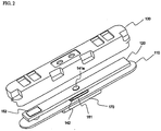
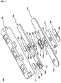
- FIG. 5 is an exploded perspective view illustrating a cap assembly according to the preferred embodiment of the present invention.
- the cap assembly 300 includes a base plate 310 mounted to an open upper end of a battery case (not shown), a PCM 320 mounted on the base plate 310, and a top cap 330 coupled to the upper end of the battery case while the top cap 330 covers the PCM 320.
- the top cap 330 is made of an insulative material.
- the base plate 310 is provided in the middle thereof with a through-hole (c) 314, through which a rivet 340 is inserted.
- the rivet 340 is connected to an anode of a battery.
- the base plate 310 is provided in a one-side part thereof with a coupling member 312, which protrudes in the direction where the PCM 320 is mounted.
- the coupling member 312 is connected to a cathode of the battery.
- the PCM 320 is provided in the middle thereof with a through-hole (b) 324 corresponding to the through-hole 314 of the base plate 310 such that the rivet 340 is inserted through the through-hole 324.
- the PCM 320 is provided in a one-side part thereof with a through-hole (a) 322, through which the coupling member 312 of the base plate 310 is inserted.
- the coupling member 312 is inserted through the through-hole 322, and the rivet 340 is inserted through the through-holes 324 and 314, thereby accomplishing the mechanical coupling and electrical connection between the base plate 310 and the PCM 320.
- the rivet 340 which is connected to the anode of the battery, specifically an electrode assembly (not shown), serves to space the base plate 310 and the PCM 320 from each other. Also, the rivet 340 constitutes a protruding terminal located on the base plate 310.
- the rivet 340 includes cylindrical bodies 341a and 341b and a plate-shaped body 342, having a predetermined thickness, interposed between the cylindrical bodies 341a and 341b.
- the upper cylindrical body 341a of the rivet 340 is inserted through the through-hole 324 of the PCM 320, and the lower cylindrical body 341b of the rivet 340 is inserted through the through-hole 314 of the base plate 310.
- the coupling member 312 of the base plate 310 which is connected to the cathode of the electrode assembly, protrudes by a length corresponding to the space distance between the PCM 320 and the base plate 310 defined by the plate-shaped body 342 of the rivet 340.
- the coupling member 312 of the base plate 310 is formed in a cylindrical shape such that the coupling member 312 corresponds to the through-hole 322 of the PCM 320.
- the gasket includes an upper gasket 350 and a lower gasket 353.
- the upper gasket 350 includes a cylindrical body 351 disposed at the upper end of the base plate 310 and inserted in the through-hole 314 of the base plate 310 such that the cylindrical body 351 covers the inner circumferential surface of the through-hole 314, and an upper end 352 formed in a plate-shaped structure to cover the upper end surface of the through-hole 314.
- the lower gasket 353 is disposed at the lower end of the base plate 310.
- the lower gasket 352 is formed in a plate-shaped structure to cover the lower end surface of the through-hole (c) 314.
- an insertion hole 354 through which the lower cylindrical body 341b of the rivet 340 is inserted.
- the conductive plate 360 is a region where the anode terminal of the electrode assembly is connected by welding.
- the conductive plate 360 is provided with an opening 364, through which the lower end of the rivet 340 is inserted.
- the lower gasket 353 mounted to the lower end of the base plate 310 has a size greater than that of the conductive plate 360 such that contact between the conductive plate 360 and the base plate 310 is prevented.
- the lower gasket 353 may be formed in a structure to cover the upper end surface and the side surface of the conductive plate 360.
- a depression 315 in which the plate-shaped body 342 of the rivet 340 is located when the rivet 340 is inserted through the through-hole 314.
- the rivet 340 is inserted through the through-hole 314 of the base plate 310 via the upper gasket 350.
- the depression 315 of the base plate 310 has a size corresponding to that of the upper gasket 350.
- the upper gasket 350 and the lower gasket 353 are fitted to the middle through-hole 314 of the base plate 310. While the conductive plate 360 is positioned at the lower end of the lower gasket 353, the lower cylindrical body 341b of the rivet 340 is inserted through the insertion holes 354 of the upper and lower gaskets 350 and 353 and the opening 364 of the conductive plate 360.
- the lower cylindrical body 341b of the rivet 340 has a length sufficient to partially protrude from the opening 364 of the conductive plate 360 when the lower cylindrical body 341b of the rivet 340 is inserted as described above. Consequently, it is possible to press (rivet) the protruding lower end of the rivet 340, thereby accomplishing the coupling between the rivet 340 and the base plate 310.
- the upper cylindrical body 341a of the rivet 340 is inserted through the middle through-hole 324 of the PCM 320.
- the upper cylindrical body 341a of the rivet 340 also has a length sufficient to partially protrude from the through-hole 324 of the PCM 320 when the upper cylindrical body 341a of the rivet 340 is inserted as described above. Consequently, it is possible to press the protruding upper end of the rivet 340, thereby accomplishing the coupling between the rivet 340 and the PCM 320.
- the coupling member 312 protruding from the one-side part of the base plate 310 is inserted through the side through-hole 322 of the PCM 320.
- the coupling member 312 of the base plate 310 has a length sufficient to partially protrude from the through-hole 322 of the PCM 320 when the coupling member 312 is inserted through the through-hole 322 of the PCM 320 as described above. Consequently, it is possible to press the protruding lower end of the rivet 150, thereby accomplishing the coupling between the coupling member 312 and the PCM 320.
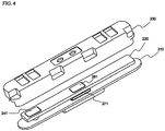
- the base plate 310 While the mechanical coupling is accomplished between the PCM 320 and the base plate 310, the base plate 310 is located at the open upper end of the battery case (not shown), and then the base plate 310 is coupled to the battery case by welding. After that, the top cap 330 is mounted to the upper end of the battery case.
- the mechanical coupling between the PCM 320 and the base plate 310 using the rivet 340 and the coupling member 312 is not limited by the above-described coupling process. In other words, the mechanical coupling between the PCM 320 and the base plate 310 may be performed in various manners.
- the base plate 310 and the PCM 320 are mechanically coupled with each other while the base plate 310 and the PCM 320 are spaced a predetermined distance from each other due to the plate-shaped body 342 of the rivet 340 interposed between the base plate 310 and the PCM 320, and the electrical connection between the base plate 310 and the PCM 320 is accomplished by the rivet 340 and the coupling member 312 protruding from the base plate 310.
- the no-welding type battery pack using the one or more forced-inserting type rivets can be manufactured without welding or soldering requiring an excessive amount of time and skilled technique during the electrical connection between the battery cell and the PCM.
- the assembly process of the battery pack is simplified, and therefore, the manufacturing time of the battery pack is reduced. Consequently, the manufacturing costs of the battery pack are decreased, the automation of the assembly process is accomplished, and the structural stability of the battery pack is improved.
Landscapes
- Chemical & Material Sciences (AREA)
- Chemical Kinetics & Catalysis (AREA)
- Electrochemistry (AREA)
- General Chemical & Material Sciences (AREA)
- Connection Of Batteries Or Terminals (AREA)
- Battery Mounting, Suspending (AREA)
- Sealing Battery Cases Or Jackets (AREA)
Claims (7)
- Kappenanordnung, umfassend:eine Basisplatte, die an ein oberes offenes Ende eines Batteriegehäuses montiert ist;ein Schutzschaltungsmodul (PCM), das an der Basisplatte montiert ist; undeine obere Kappe, die mit dem oberen Ende des Batteriegehäuses gekoppelt ist, während die obere Kappe das PCM bedeckt, wobei die obere Kappe aus einem isolierenden Material hergestellt ist, wobeidie elektrische Verbindung und die mechanische Kopplung zwischen dem PCM und der Basisplatte durch einen Niet des Zwangseinführung-Typs ausgeführt werden,das PCM zwei Durchgangslöcher (a, b) hat, die jeweils mit einer Kathode und einer Anode einer Batterie verbunden sind, und die Basisplatte mit einem Kopplungselement und einem Durchgangsloch (c) versehen ist, die jeweils den Durchgangslöchern des PCM entsprechen,während das PCM an der Basisplatte positioniert ist, das Kopplungselement durch das Durchgangsloch (a) eingeführt ist,der Niet durch das Durchgangsloch (b) und das Durchgangsloch (c) eingeführt ist, um so die elektrische Verbindung und mechanische Kopplung zwischen dem PCM und der Basisplatte auszuführen, undeine Dichtung an dem Durchgangsloch (c) der Basisplatte montiert ist, durch welches der Niet eingeführt ist, derart dass die Dichtung die obere Endoberfläche, die untere Endoberfläche und die innere Umfangsoberfläche des Durchgangslochs (c) bedeckt, wobei die Dichtung aus einem isolierenden Material hergestellt ist,wobei der Niet einen zylindrischen Körper und einen plattenförmigen Körper mit einer vorbestimmten Dicke aufweist, der an der Mitte des zylindrischen Körpers gebildet ist, derart dass der Niet dazu dient, das PCM und die Basisplatte um einen vorbestimmten Abstand voneinander zu beabstanden, und der Niet einen vorstehenden Anschluss ausbildet, der sich an der Basisplatte befindet, undwobei die Basisplatte um das Durchgangsloch (c) von ihr herum, durch welches der Niet eingeführt ist, mit einer Vertiefung versehen ist, in welcher sich der plattenförmige Körper des Niets befindet.
- Kappenanordnung nach Anspruch 1, wobei das Kopplungselement von der Basisplatte um eine Länge hervorsteht, die dem Abstand zwischen dem PCM und der Basisplatte entspricht, während der Niet durch das durchgehende Loch (c) der Basisplatte eingeführt ist.
- Kappenanordnung nach Anspruch 1, weiter umfassend:eine leitfähige Platte, die an das untere Ende der Dichtung montiert ist, wobei die leitfähige Platte eine Öffnung hat, die mit einem Elektrodenanschluss einer Batteriezelle verbunden ist, durch welche das untere Ende des Niets eingeführt ist.
- Kappenanordnung nach Anspruch 3, wobei der Niet eine Länge hat, die ausreichend ist, um durch das PCM, die Basisplatte, die Dichtung und die leitfähige Platte eingeführt zu werden, und an die obere Endoberfläche der Dichtung und die untere Endoberfläche der leitfähigen Platte gepresst zu werden.
- Kappenanordnung nach Anspruch 1, wobei die Dichtung zwei Elemente aufweist, die an die oberen und unteren Endoberflächen der Basisplatte gekoppelt sind, oder die Dichtung in einer integrierten Struktur durch Einsatzspritzgießen gebildet ist.
- Batteriepack, das in einer Struktur aufgebaut ist, in welcher eine Kappenanordnung nach einem der Ansprüche 1 bis 5 an ein oberes offenes Ende eines Batteriegehäuses gekoppelt ist, das eine Elektrodenanordnung enthält.
- Batteriepack nach Anspruch 6, wobei das Batteriegehäuse ein prismatischer Metallbehälter ist.
Applications Claiming Priority (4)
| Application Number | Priority Date | Filing Date | Title |
|---|---|---|---|
| KR1020050127545A KR100861714B1 (ko) | 2005-12-22 | 2005-12-22 | 리벳을 이용한 무용접 방식의 전지팩 |
| KR1020060004728A KR100821858B1 (ko) | 2006-01-17 | 2006-01-17 | 무용접 체결 방식의 전지팩 |
| KR1020060013569A KR100930473B1 (ko) | 2006-02-13 | 2006-02-13 | 억지끼움 결합 방식의 리벳을 이용한 무용접 방식의 전지팩 |
| EP06835227.7A EP1982367B1 (de) | 2005-12-22 | 2006-12-18 | Batteriepack des nicht-schweiss-typs mit presspass-niete |
Related Parent Applications (2)
| Application Number | Title | Priority Date | Filing Date |
|---|---|---|---|
| EP06835227.7A Division EP1982367B1 (de) | 2005-12-22 | 2006-12-18 | Batteriepack des nicht-schweiss-typs mit presspass-niete |
| EP06835227.7A Division-Into EP1982367B1 (de) | 2005-12-22 | 2006-12-18 | Batteriepack des nicht-schweiss-typs mit presspass-niete |
Publications (3)
| Publication Number | Publication Date |
|---|---|
| EP3048657A2 EP3048657A2 (de) | 2016-07-27 |
| EP3048657A3 EP3048657A3 (de) | 2016-08-10 |
| EP3048657B1 true EP3048657B1 (de) | 2017-10-25 |
Family
ID=38188792
Family Applications (2)
| Application Number | Title | Priority Date | Filing Date |
|---|---|---|---|
| EP06835227.7A Active EP1982367B1 (de) | 2005-12-22 | 2006-12-18 | Batteriepack des nicht-schweiss-typs mit presspass-niete |
| EP16153344.3A Active EP3048657B1 (de) | 2005-12-22 | 2006-12-18 | Schweissloses batteriepack mit eindrückniet |
Family Applications Before (1)
| Application Number | Title | Priority Date | Filing Date |
|---|---|---|---|
| EP06835227.7A Active EP1982367B1 (de) | 2005-12-22 | 2006-12-18 | Batteriepack des nicht-schweiss-typs mit presspass-niete |
Country Status (5)
| Country | Link |
|---|---|
| US (1) | US7976969B2 (de) |
| EP (2) | EP1982367B1 (de) |
| JP (2) | JP5323495B2 (de) |
| TW (1) | TWI335091B (de) |
| WO (1) | WO2007073066A1 (de) |
Families Citing this family (30)
| Publication number | Priority date | Publication date | Assignee | Title |
|---|---|---|---|---|
| KR100791551B1 (ko) * | 2007-08-17 | 2008-01-07 | 주식회사 퓨처라인 | 보호회로모듈과 이를 포함하는 전지 및 상기보호회로모듈을 포함하는 전지 제조 방법 |
| KR100867928B1 (ko) | 2007-09-27 | 2008-11-10 | 삼성에스디아이 주식회사 | 보호회로기판 및 이를 구비하는 배터리 팩 |
| KR100929034B1 (ko) * | 2007-10-15 | 2009-11-26 | 삼성에스디아이 주식회사 | 배터리 팩 및 그의 제조 방법 |
| KR100928120B1 (ko) * | 2007-11-07 | 2009-11-24 | 삼성에스디아이 주식회사 | 이차 전지 |
| KR100943579B1 (ko) | 2007-11-19 | 2010-02-23 | 삼성에스디아이 주식회사 | 이차전지용 기판 조립체 및 이를 이용한 배터리 팩 |
| US9017842B2 (en) * | 2007-11-23 | 2015-04-28 | Lg Chem, Ltd. | Secondary battery pack providing excellent productivity and structural stability |
| WO2009069943A2 (en) * | 2007-11-29 | 2009-06-04 | Lg Chem, Ltd. | Battery pack containing pcm employed with safety member |
| KR100959870B1 (ko) * | 2007-12-13 | 2010-05-27 | 삼성에스디아이 주식회사 | 보호회로 조립체 및 이를 구비하는 배터리 팩 |
| KR100959871B1 (ko) * | 2007-12-17 | 2010-05-27 | 삼성에스디아이 주식회사 | 보호회로기판 및 이를 구비하는 배터리 팩 |
| KR100971339B1 (ko) * | 2008-04-18 | 2010-07-20 | 삼성에스디아이 주식회사 | 배터리 팩 |
| KR100965684B1 (ko) * | 2008-06-03 | 2010-06-24 | 삼성에스디아이 주식회사 | 전지 팩 |
| US20100055560A1 (en) * | 2008-08-29 | 2010-03-04 | Youngcheol Jang | Secondary battery |
| KR101023922B1 (ko) | 2008-10-14 | 2011-03-22 | 주식회사 엘지화학 | 원통형 이차전지 팩 |
| KR101084982B1 (ko) * | 2008-10-14 | 2011-11-18 | 주식회사 엘지화학 | 신규한 구조의 이차전지 팩 |
| KR20100060677A (ko) * | 2008-11-28 | 2010-06-07 | 삼성에스디아이 주식회사 | 배터리 팩 |
| KR101023898B1 (ko) * | 2008-12-02 | 2011-03-22 | 삼성에스디아이 주식회사 | 이차 전지 |
| KR101040975B1 (ko) | 2009-02-26 | 2011-06-16 | 주식회사 엘지화학 | 신규한 구조의 이차전지 팩 |
| KR101030900B1 (ko) * | 2009-05-15 | 2011-04-22 | 삼성에스디아이 주식회사 | 이차전지 |
| KR101030906B1 (ko) * | 2009-06-18 | 2011-04-22 | 삼성에스디아이 주식회사 | 이차 전지 |
| US9130224B2 (en) | 2009-07-06 | 2015-09-08 | Samsung Sdi Co., Ltd. | Battery pack and method of manufacturing battery pack |
| US20110081559A1 (en) * | 2009-10-07 | 2011-04-07 | Research In Motion Limited | Low noise battery |
| US9263724B2 (en) * | 2009-10-12 | 2016-02-16 | Samsung Sdi Co., Ltd. | Battery pack |
| KR101211755B1 (ko) * | 2010-05-20 | 2012-12-12 | 에스비리모티브 주식회사 | 이차 전지 |
| KR101108212B1 (ko) | 2010-06-08 | 2012-01-31 | 정기범 | 자연방전 방지용 충전 장치 |
| KR101106094B1 (ko) * | 2010-09-13 | 2012-01-18 | 삼성에스디아이 주식회사 | 배터리 팩 |
| US8858270B2 (en) * | 2011-01-25 | 2014-10-14 | The Gillette Company | Rechargeable battery pack including low-resistance battery-pack interconnect |
| TW201304252A (zh) * | 2011-07-13 | 2013-01-16 | Life Resources Inc | 電池模組 |
| KR101371364B1 (ko) | 2011-10-25 | 2014-03-11 | 주식회사 엘지화학 | 단자블록을 포함하는 탑 캡 어셈블리 |
| KR102210888B1 (ko) | 2016-07-21 | 2021-02-02 | 삼성에스디아이 주식회사 | 배터리 팩 |
| JP7138594B2 (ja) | 2019-03-20 | 2022-09-16 | 三菱重工マリタイムシステムズ株式会社 | 船舶 |
Family Cites Families (25)
| Publication number | Priority date | Publication date | Assignee | Title |
|---|---|---|---|---|
| EP0674351B1 (de) * | 1994-03-03 | 2002-08-14 | Japan Storage Battery Company Limited | Sicherheitsanordnung für Batterie |
| JPH11154505A (ja) * | 1997-11-20 | 1999-06-08 | Alps Electric Co Ltd | 圧力遮断センサ |
| EP1093178A4 (de) * | 1999-03-30 | 2007-12-05 | Matsushita Electric Ind Co Ltd | Wieder aufladbare batterie mit schutzschaltung |
| JP2000312435A (ja) * | 1999-04-27 | 2000-11-07 | Hosiden Corp | 圧力破砕型保護デバイスを用いた充電型電池および当該充電型電池を用いた携帯型電子機器 |
| WO2002027819A1 (en) * | 2000-09-29 | 2002-04-04 | Lg Chemical Co., Ltd. | Safety plate of secondary battery |
| JP2002216743A (ja) * | 2001-01-19 | 2002-08-02 | Alps Electric Co Ltd | 電池用圧力遮断センサ |
| JP4601870B2 (ja) * | 2001-07-10 | 2010-12-22 | 三洋ジーエスソフトエナジー株式会社 | 電池パック |
| JP2002343315A (ja) * | 2001-05-10 | 2002-11-29 | Alps Electric Co Ltd | 電池蓋ユニット |
| KR100822188B1 (ko) | 2001-10-24 | 2008-04-16 | 삼성에스디아이 주식회사 | 각형 이차전지 |
| JP2003208886A (ja) * | 2002-01-16 | 2003-07-25 | Mitsubishi Chemicals Corp | 電 池 |
| JP4266097B2 (ja) * | 2002-04-17 | 2009-05-20 | 三洋ジーエスソフトエナジー株式会社 | 電池 |
| JP4304919B2 (ja) * | 2002-06-04 | 2009-07-29 | 株式会社ジーエス・ユアサコーポレーション | 電池 |
| JP4300768B2 (ja) * | 2002-08-06 | 2009-07-22 | パナソニック株式会社 | 電池装置 |
| JP3843067B2 (ja) * | 2002-12-27 | 2006-11-08 | 三洋電機株式会社 | パック電池 |
| JP4408027B2 (ja) * | 2003-05-12 | 2010-02-03 | パナソニック株式会社 | 電池パック |
| KR100551887B1 (ko) * | 2003-10-24 | 2006-02-14 | 삼성에스디아이 주식회사 | 이차전지 |
| KR100561298B1 (ko) * | 2004-01-13 | 2006-03-15 | 삼성에스디아이 주식회사 | 이차 전지 |
| BRPI0506603B8 (pt) * | 2004-01-28 | 2023-01-10 | Lg Chemical Ltd | Bateria secundária de estrutura tipo montagem |
| KR20040015314A (ko) | 2004-01-28 | 2004-02-18 | 임승준 | 무용접 접점 방식의 배터리 팩 |
| KR100571234B1 (ko) | 2004-02-10 | 2006-04-13 | 삼성에스디아이 주식회사 | 이차 전지 |
| BRPI0507558B8 (pt) * | 2004-02-13 | 2023-01-10 | Lg Chemical Ltd | Pacote de bateria |
| EP1716608B1 (de) * | 2004-02-18 | 2014-05-14 | LG Chem Ltd. | Integrale kappenbaugruppe mit einer schutzschaltungs-leiterplatte und sekundärbatterie damit |
| JP4837294B2 (ja) * | 2005-02-28 | 2011-12-14 | パナソニック株式会社 | 電池パック |
| JP4568091B2 (ja) * | 2004-11-16 | 2010-10-27 | 三洋電機株式会社 | パック電池 |
| JP4404847B2 (ja) * | 2004-11-29 | 2010-01-27 | 三星エスディアイ株式会社 | リチウム二次電池 |
-
2006
- 2006-12-18 EP EP06835227.7A patent/EP1982367B1/de active Active
- 2006-12-18 WO PCT/KR2006/005509 patent/WO2007073066A1/en active Application Filing
- 2006-12-18 EP EP16153344.3A patent/EP3048657B1/de active Active
- 2006-12-18 JP JP2008547098A patent/JP5323495B2/ja active Active
- 2006-12-20 TW TW095147936A patent/TWI335091B/zh active
- 2006-12-20 US US11/613,709 patent/US7976969B2/en active Active
-
2013
- 2013-05-02 JP JP2013097087A patent/JP5635646B2/ja active Active
Non-Patent Citations (1)
| Title |
|---|
| None * |
Also Published As
| Publication number | Publication date |
|---|---|
| US7976969B2 (en) | 2011-07-12 |
| TW200746497A (en) | 2007-12-16 |
| EP1982367A4 (de) | 2014-05-21 |
| EP3048657A2 (de) | 2016-07-27 |
| EP3048657A3 (de) | 2016-08-10 |
| TWI335091B (en) | 2010-12-21 |
| EP1982367B1 (de) | 2016-10-05 |
| US20070160878A1 (en) | 2007-07-12 |
| JP5323495B2 (ja) | 2013-10-23 |
| JP2009521094A (ja) | 2009-05-28 |
| JP5635646B2 (ja) | 2014-12-03 |
| WO2007073066A1 (en) | 2007-06-28 |
| JP2013175472A (ja) | 2013-09-05 |
| EP1982367A1 (de) | 2008-10-22 |
Similar Documents
| Publication | Publication Date | Title |
|---|---|---|
| EP3048657B1 (de) | Schweissloses batteriepack mit eindrückniet | |
| US7939189B2 (en) | No-welding type battery pack | |
| EP2215673B1 (de) | Sekundärbatteriepackung mit kompaktem aufbau | |
| EP2218125B1 (de) | Schutzschaltungsmodul mit verbesserter montagestruktur und batteriepack damit | |
| KR100861714B1 (ko) | 리벳을 이용한 무용접 방식의 전지팩 | |
| KR20050095949A (ko) | 캡 조립체 및 이를 구비한 이차 전지 | |
| KR20090039503A (ko) | 우수한 에너지 밀도의 이차전지 팩 및 그것을 위한 pcm어셈블리 | |
| EP1946421B1 (de) | Vorfabrizierter pcm und diesen enthaltendes batteriepack | |
| KR100930473B1 (ko) | 억지끼움 결합 방식의 리벳을 이용한 무용접 방식의 전지팩 | |
| KR100821858B1 (ko) | 무용접 체결 방식의 전지팩 | |
| KR100635730B1 (ko) | 원통형 리튬 이차 전지 및 이의 제조 방법 | |
| KR100883920B1 (ko) | 무용접 접촉 연결방식의 보호회로 모듈 및 그것을 포함하는전지팩 | |
| KR100851959B1 (ko) | 단자핀 결합구조의 보호회로모듈을 가진 이차전지 | |
| KR100936259B1 (ko) | 우수한 제조공정성 및 구조적 안정성의 이차전지 팩 | |
| KR20090055791A (ko) | 콤팩트한 구조의 이차전지 팩 | |
| KR20060027282A (ko) | 원통형 리튬 이차 전지 |
Legal Events
| Date | Code | Title | Description |
|---|---|---|---|
| PUAI | Public reference made under article 153(3) epc to a published international application that has entered the european phase |
Free format text: ORIGINAL CODE: 0009012 |
|
| PUAL | Search report despatched |
Free format text: ORIGINAL CODE: 0009013 |
|
| 17P | Request for examination filed |
Effective date: 20160129 |
|
| AC | Divisional application: reference to earlier application |
Ref document number: 1982367 Country of ref document: EP Kind code of ref document: P |
|
| AK | Designated contracting states |
Kind code of ref document: A2 Designated state(s): DE FR |
|
| AK | Designated contracting states |
Kind code of ref document: A3 Designated state(s): DE FR |
|
| RIC1 | Information provided on ipc code assigned before grant |
Ipc: H01M 2/34 20060101ALI20160706BHEP Ipc: H01M 2/10 20060101ALI20160706BHEP Ipc: H01M 10/052 20100101ALI20160706BHEP Ipc: H01M 2/22 20060101ALI20160706BHEP Ipc: H01M 2/08 20060101ALI20160706BHEP Ipc: H01M 2/04 20060101AFI20160706BHEP |
|
| GRAP | Despatch of communication of intention to grant a patent |
Free format text: ORIGINAL CODE: EPIDOSNIGR1 |
|
| INTG | Intention to grant announced |
Effective date: 20170713 |
|
| GRAS | Grant fee paid |
Free format text: ORIGINAL CODE: EPIDOSNIGR3 |
|
| GRAA | (expected) grant |
Free format text: ORIGINAL CODE: 0009210 |
|
| AC | Divisional application: reference to earlier application |
Ref document number: 1982367 Country of ref document: EP Kind code of ref document: P |
|
| AK | Designated contracting states |
Kind code of ref document: B1 Designated state(s): DE FR |
|
| REG | Reference to a national code |
Ref country code: FR Ref legal event code: PLFP Year of fee payment: 12 |
|
| REG | Reference to a national code |
Ref country code: DE Ref legal event code: R096 Ref document number: 602006053973 Country of ref document: DE |
|
| REG | Reference to a national code |
Ref country code: DE Ref legal event code: R097 Ref document number: 602006053973 Country of ref document: DE |
|
| PLBE | No opposition filed within time limit |
Free format text: ORIGINAL CODE: 0009261 |
|
| STAA | Information on the status of an ep patent application or granted ep patent |
Free format text: STATUS: NO OPPOSITION FILED WITHIN TIME LIMIT |
|
| 26N | No opposition filed |
Effective date: 20180726 |
|
| REG | Reference to a national code |
Ref country code: DE Ref legal event code: R079 Ref document number: 602006053973 Country of ref document: DE Free format text: PREVIOUS MAIN CLASS: H01M0002040000 Ipc: H01M0050147000 |
|
| REG | Reference to a national code |
Ref country code: DE Ref legal event code: R081 Ref document number: 602006053973 Country of ref document: DE Owner name: LG ENERGY SOLUTION LTD., KR Free format text: FORMER OWNER: LG CHEM, LTD., SEOUL, KR Ref country code: DE Ref legal event code: R081 Ref document number: 602006053973 Country of ref document: DE Owner name: LG ENERGY SOLUTION, LTD., KR Free format text: FORMER OWNER: LG CHEM, LTD., SEOUL, KR |
|
| P01 | Opt-out of the competence of the unified patent court (upc) registered |
Effective date: 20230408 |
|
| REG | Reference to a national code |
Ref country code: DE Ref legal event code: R081 Ref document number: 602006053973 Country of ref document: DE Owner name: LG ENERGY SOLUTION, LTD., KR Free format text: FORMER OWNER: LG ENERGY SOLUTION LTD., SEOUL, KR |
|
| PGFP | Annual fee paid to national office [announced via postgrant information from national office to epo] |
Ref country code: FR Payment date: 20231121 Year of fee payment: 18 Ref country code: DE Payment date: 20231120 Year of fee payment: 18 |