EP3048614B1 - Verfahren und vorrichtung zur kapselung eines brennstabes oder eines brennstababschnittes für eine zwischenlagerung - Google Patents
Verfahren und vorrichtung zur kapselung eines brennstabes oder eines brennstababschnittes für eine zwischenlagerung Download PDFInfo
- Publication number
- EP3048614B1 EP3048614B1 EP16155068.6A EP16155068A EP3048614B1 EP 3048614 B1 EP3048614 B1 EP 3048614B1 EP 16155068 A EP16155068 A EP 16155068A EP 3048614 B1 EP3048614 B1 EP 3048614B1
- Authority
- EP
- European Patent Office
- Prior art keywords
- container
- fuel rod
- gas
- chambers
- chamber
- Prior art date
- Legal status (The legal status is an assumption and is not a legal conclusion. Google has not performed a legal analysis and makes no representation as to the accuracy of the status listed.)
- Active
Links
Images


Classifications
-
- G—PHYSICS
- G21—NUCLEAR PHYSICS; NUCLEAR ENGINEERING
- G21F—PROTECTION AGAINST X-RADIATION, GAMMA RADIATION, CORPUSCULAR RADIATION OR PARTICLE BOMBARDMENT; TREATING RADIOACTIVELY CONTAMINATED MATERIAL; DECONTAMINATION ARRANGEMENTS THEREFOR
- G21F5/00—Transportable or portable shielded containers
- G21F5/005—Containers for solid radioactive wastes, e.g. for ultimate disposal
- G21F5/008—Containers for fuel elements
-
- F—MECHANICAL ENGINEERING; LIGHTING; HEATING; WEAPONS; BLASTING
- F26—DRYING
- F26B—DRYING SOLID MATERIALS OR OBJECTS BY REMOVING LIQUID THEREFROM
- F26B21/00—Arrangements or duct systems, e.g. in combination with pallet boxes, for supplying and controlling air or gases for drying solid materials or objects
- F26B21/02—Circulating air or gases in closed cycles, e.g. wholly within the drying enclosure
- F26B21/04—Circulating air or gases in closed cycles, e.g. wholly within the drying enclosure partly outside the drying enclosure
-
- F—MECHANICAL ENGINEERING; LIGHTING; HEATING; WEAPONS; BLASTING
- F26—DRYING
- F26B—DRYING SOLID MATERIALS OR OBJECTS BY REMOVING LIQUID THEREFROM
- F26B25/00—Details of general application not covered by group F26B21/00 or F26B23/00
- F26B25/22—Controlling the drying process in dependence on liquid content of solid materials or objects
-
- G—PHYSICS
- G21—NUCLEAR PHYSICS; NUCLEAR ENGINEERING
- G21C—NUCLEAR REACTORS
- G21C19/00—Arrangements for treating, for handling, or for facilitating the handling of, fuel or other materials which are used within the reactor, e.g. within its pressure vessel
- G21C19/26—Arrangements for removing jammed or damaged fuel elements or control elements; Arrangements for moving broken parts thereof
-
- G—PHYSICS
- G21—NUCLEAR PHYSICS; NUCLEAR ENGINEERING
- G21C—NUCLEAR REACTORS
- G21C19/00—Arrangements for treating, for handling, or for facilitating the handling of, fuel or other materials which are used within the reactor, e.g. within its pressure vessel
- G21C19/32—Apparatus for removing radioactive objects or materials from the reactor discharge area, e.g. to a storage place; Apparatus for handling radioactive objects or materials within a storage place or removing them therefrom
-
- G—PHYSICS
- G21—NUCLEAR PHYSICS; NUCLEAR ENGINEERING
- G21F—PROTECTION AGAINST X-RADIATION, GAMMA RADIATION, CORPUSCULAR RADIATION OR PARTICLE BOMBARDMENT; TREATING RADIOACTIVELY CONTAMINATED MATERIAL; DECONTAMINATION ARRANGEMENTS THEREFOR
- G21F5/00—Transportable or portable shielded containers
- G21F5/06—Details of, or accessories to, the containers
- G21F5/12—Closures for containers; Sealing arrangements
-
- F—MECHANICAL ENGINEERING; LIGHTING; HEATING; WEAPONS; BLASTING
- F26—DRYING
- F26B—DRYING SOLID MATERIALS OR OBJECTS BY REMOVING LIQUID THEREFROM
- F26B21/00—Arrangements or duct systems, e.g. in combination with pallet boxes, for supplying and controlling air or gases for drying solid materials or objects
-
- F—MECHANICAL ENGINEERING; LIGHTING; HEATING; WEAPONS; BLASTING
- F26—DRYING
- F26B—DRYING SOLID MATERIALS OR OBJECTS BY REMOVING LIQUID THEREFROM
- F26B25/00—Details of general application not covered by group F26B21/00 or F26B23/00
- F26B25/06—Chambers, containers, or receptacles
-
- Y—GENERAL TAGGING OF NEW TECHNOLOGICAL DEVELOPMENTS; GENERAL TAGGING OF CROSS-SECTIONAL TECHNOLOGIES SPANNING OVER SEVERAL SECTIONS OF THE IPC; TECHNICAL SUBJECTS COVERED BY FORMER USPC CROSS-REFERENCE ART COLLECTIONS [XRACs] AND DIGESTS
- Y02—TECHNOLOGIES OR APPLICATIONS FOR MITIGATION OR ADAPTATION AGAINST CLIMATE CHANGE
- Y02E—REDUCTION OF GREENHOUSE GAS [GHG] EMISSIONS, RELATED TO ENERGY GENERATION, TRANSMISSION OR DISTRIBUTION
- Y02E30/00—Energy generation of nuclear origin
- Y02E30/30—Nuclear fission reactors
Definitions
- the invention relates to a method and a device for encapsulating a fuel rod or a fuel rod section for temporary storage.
- defective fuel rods or fuel rod sections vacuum and fluid-tight in containers or capsules are introduced, as for example from the DE 196 40 393 B4 , of the EP 1 248 270 A1 , of the EP 1 600 982 B1 and the WO 2010/084122 A1 are known. Since the encapsulation of a fuel rod or a fuel rod portion as close as possible to the location of the original storage, ie within the fuel storage pool under water, it is inevitable that when introducing the fuel rod or fuel rod portion in the open container water penetrates into it. However, this water must be removed from the fuel rod container, as it would evaporate due to the Nachzerfallstage and would lead to an impermissibly high internal pressure.
- closure elements used a channel through which gas can be injected, so that the water in the container is expelled.
- a coaxial channel is provided in each sealing plug, in which a spring-loaded valve is arranged, which closes the channel in a fluid-tight manner with a closing element.
- these closing elements are lifted by means of a plunger from its valve seat and it is injected via a then open channel, a gas and expelled the water through the also open channel of the opposite closure element.
- this expulsion of the water takes place when the closure elements are by screwing, welding or deformation in their final assembly position in which they close the container fluid-tight.
- A1 known container is provided as a closure element, a cap which is pushed onto a hollow cylindrical container part and integrally connected to the end face.
- the closure of the container takes place in a fluid-tight chamber.
- the liquid contained in the chamber is withdrawn and then carried out a vacuum drying. Due to the inside of the equipped with a fuel rod container between the fuel rod and the inner wall of the container present narrow column, residual water may possibly remain in the container.
- the invention is therefore based on the object to provide a method for encapsulating a fuel rod or a fuel rod section, in which this gas-tight and enclosed in a container, and with which it is possible to make a quantitative statement about the content of residual water in the container.
- the invention is also based on the object to provide a device with which a fuel rod or a fuel rod portion containing container with a known content of residual water can be closed.
- first and second chambers are rigidly connected to one another via a connecting tube along the system axis, into which the container can be inserted in such a way that it projects beyond the connecting tube with its free ends.
- At least one sealing element is arranged between the container and the connecting tube, which is adjustable in such a way that the chambers are fluidically connected to one another exclusively via the container.
- an adjustable sealing element is arranged at both ends of the connecting tube, a cylindrical gap space is formed between the container and the connecting tube, which is sealed fluid-tight with respect to the chambers.
- the container is rinsed again with flushing gas before closing.
- the method steps e) and f) are carried out successively several times cyclically, wherein in each cycle of the method step e) and then the method step f) are performed.
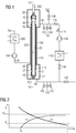
- Fig. 1 a provided with a fuel rod 20 container 2 has been introduced into a device in which the remaining water in the container 2 is removed from the container 2 and in which he gas-tight after the reduction of the residual water content to or below a predetermined maximum allowable limit becomes.
- the dashed lines drawn in the figure fuel rod 20 has been introduced into the container 2, on the ends of an example of the EP 1 600 982 B1 Known closure element 10 is screwed in an intermediate position.
- the device comprises a first and a second chamber 50, 52 which are spaced from each other on a common system axis 53.
- the first and second chambers 50, 52 are rigidly connected to one another along this system axis 53 via a connecting tube 100 which is open at both ends.
- the ends of the connecting tube 100 form in the first and second chambers 50, 52 a first or second opening 56, 57 through which a container 2 inserted into the connecting tube 100 with its free ends projects beyond the connecting tube 100 into the chambers 50, 52.
- connecting tube 100 and the container 2 undeliverable sealing elements 116 are arranged in the region of these free ends, which close the existing between connecting tube 100 and container 2 cylindrical gap space 119, so that first and second chamber 50, 52 arranged between this container 2 exclusively on this can be fluidly connected to each other.
- the container 2 provided with the closure element 10 is mounted in a rotationally fixed manner in the second chamber 52 in a receptacle 200 adapted to the closure element 10.
- a handling tool 202 is inserted, which engages around the closure element 10 torque-locking and with which the two closure elements 10 can be screwed to the container 2 in a gas-tight end position.
- an inlet line 66 is connected to a purge gas G, which flows through the container 2 into the second chamber 52 and this via a Exit line 69 leaves.
- Inlet line 66 and outlet line 69 are connected via valves 134 and 136 to a bypass line 118 running outside of the chambers 50, 52, so that by closing valves 126 and 130 located in the inlet line 66 and outlet line 69 for the purge gas G, a closed gas circulation arises whose volume exceeds the free volume of the container 2 by orders of magnitude and a multiple, more than a 10-fold, in the embodiment, about 50 times this volume.
- a pump 140 and a heater 142 for circulating or heating of a gas in the gas circulation circuit H are arranged.
- measuring devices 150, 152 and 154 are arranged in the gas circulation, with which the temperature, the relative humidity or the pressure of the inflowing into the first chamber 50 and out of the second chamber 52 heating gas H can be measured.
- the connecting tube 100 is also surrounded by an arranged between the chambers 50, 52 outer tube 202 which is connected to a heating circuit 204 in which also heated with a heater 206 fluid medium M is circulated by a pump 208, so that the connecting pipe 100th thermally isolated from the environment.
- a thermal insulation can also be achieved by introducing heat-insulating material or heating elements between connecting tube 100 and outer tube 202.
- the deliverable sealing members 116 are opened, and by blowing purge gas G, the processing chambers 50, 52 and the clearance space 119 are dehydrated via the exhaust passage 69. Thereafter, the gap space 119 is closed with the sealing elements 116 and the water contained in the container 2 between the fuel rod 20 and the inner wall of the container 2 is expelled with the aid of the purge gas G. Thereafter, the valves 126, 130 are closed and the valves 134 and 136 located in the bypass line 118 are opened. Subsequently, the heating gas H located in the bypass line 118 is continuously circulated in this closed gas cycle.
- the temperature, the moisture content and the pressure of the flowing gas flowing in the gas cycle H are detected.
- the values measured in the outlet line 69 for pressure, temperature and relative humidity content can be determined in the fuel gas H absolute water or moisture content in kg / m 3 and its temporal evolution are recorded.
- the absolute mass of the water vapor present in the container 2 can now be determined in grams with known free volume of the container 2 and the fuel rod 20.
- the valves 134 and 136 are closed.
- the amount of water remaining within the container 2 is known.
- the container 2 could then be sealed gas-tight.
- the valves 126 and 130 are opened again and the container 2 is rinsed again with purge gas G.
- the water vapor contained in the container 2 and in the Brennstabplena is expelled, so that the amount of water within the container 2 is additionally reduced. Accordingly, the previously determined remaining amount may be regarded as an upper value which is larger than the actual remaining amount.
- the container 2 can then be welded to the closure elements 10 or subjected to a further treatment explained below.
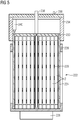
- the container 2 is removed from the device and moved by means of a handling tool 220 in a capsule quiver 222, the in Fig. 3 is shown and is constructed from a cylindrical receiving tube 224 which is arranged in a frame 226 having a foot part 228.
- This capsule quiver 222 is provided for receiving a plurality of containers 2.
- a plurality of axially spaced grid-shaped spacers 229 are arranged in the capsule quiver 222, in whose cells the containers 2 are guided.
- a lid 230 is placed after filling the capsule bag 222 with containers 2 on the receiving tube 224, which has a central suction lance 232, which leads to the bottom of the capsule bag 222 and serves to suck off water located in the capsule quiver 222.
- a hood 234 is fitted in a fluid-tight manner, through which a suction line 236 is passed, which is fluidically connected to the suction lance 232 via an opening 237 located in the cover 230.
- a suction line 236 located in the capsule quiver 222 water is sucked with simultaneous supply of purge gas G via an insertion port 238.
- heating gas H is supplied via the introduction opening 238 and discharged via the suction line 236. Unlike the drying of the container 2, the heating gas H is not performed in a closed circuit.
- the heating gas H is passed through the capsule quiver 222 until the absolute moisture content X reaches or falls below a predetermined limit value X g .
- the time course of the absolute moisture content X is in the diagram of Fig. 2 shown in curve b. This ensures that the absolute content of the water inside the capsule bag 222 does not exceed predetermined maximum values. In this way, a reliable statement about whether predetermined limits are met.
- the lid is welded to the receiving tube 224 with a welding device 240 rotatably mounted inside the hood 234 about the longitudinal central axis of the receiving tube 224.
- the opening 237 located in the cover 230 also welds to the suction lance 232.
- ultrasonic testing devices may optionally be arranged in the hood 234, with which a check of the welds is possible.
- gem. Fig. 7 removed the hood 234 and placed on the frame 226 a transport head 240, with the transport of the sealed capsule bag 222 is facilitated.
Landscapes
- Engineering & Computer Science (AREA)
- Physics & Mathematics (AREA)
- General Engineering & Computer Science (AREA)
- High Energy & Nuclear Physics (AREA)
- Plasma & Fusion (AREA)
- Mechanical Engineering (AREA)
- Monitoring And Testing Of Nuclear Reactors (AREA)
- Filling Or Discharging Of Gas Storage Vessels (AREA)
- Life Sciences & Earth Sciences (AREA)
- Health & Medical Sciences (AREA)
- Molecular Biology (AREA)
- Microbiology (AREA)
Applications Claiming Priority (4)
| Application Number | Priority Date | Filing Date | Title |
|---|---|---|---|
| DE102012203347 | 2012-03-02 | ||
| DE102012210409 | 2012-06-20 | ||
| DE201210212006 DE102012212006A1 (de) | 2012-03-02 | 2012-07-10 | Verfahren und Vorrichtung zur Kapselung eines Brennstabes oder eines Brennstababschnittes für eine Zwischenlagerung |
| EP13710803.1A EP2820654B1 (de) | 2012-03-02 | 2013-02-28 | Verfahren und vorrichtung zur lagerung von behältern, in denen jeweils ein brennstab oder brennstababschnitt gekapselt ist. |
Related Parent Applications (2)
| Application Number | Title | Priority Date | Filing Date |
|---|---|---|---|
| EP13710803.1A Division-Into EP2820654B1 (de) | 2012-03-02 | 2013-02-28 | Verfahren und vorrichtung zur lagerung von behältern, in denen jeweils ein brennstab oder brennstababschnitt gekapselt ist. |
| EP13710803.1A Division EP2820654B1 (de) | 2012-03-02 | 2013-02-28 | Verfahren und vorrichtung zur lagerung von behältern, in denen jeweils ein brennstab oder brennstababschnitt gekapselt ist. |
Publications (2)
| Publication Number | Publication Date |
|---|---|
| EP3048614A1 EP3048614A1 (de) | 2016-07-27 |
| EP3048614B1 true EP3048614B1 (de) | 2018-01-17 |
Family
ID=49081675
Family Applications (2)
| Application Number | Title | Priority Date | Filing Date |
|---|---|---|---|
| EP16155068.6A Active EP3048614B1 (de) | 2012-03-02 | 2013-02-28 | Verfahren und vorrichtung zur kapselung eines brennstabes oder eines brennstababschnittes für eine zwischenlagerung |
| EP13710803.1A Active EP2820654B1 (de) | 2012-03-02 | 2013-02-28 | Verfahren und vorrichtung zur lagerung von behältern, in denen jeweils ein brennstab oder brennstababschnitt gekapselt ist. |
Family Applications After (1)
| Application Number | Title | Priority Date | Filing Date |
|---|---|---|---|
| EP13710803.1A Active EP2820654B1 (de) | 2012-03-02 | 2013-02-28 | Verfahren und vorrichtung zur lagerung von behältern, in denen jeweils ein brennstab oder brennstababschnitt gekapselt ist. |
Country Status (7)
| Country | Link |
|---|---|
| US (2) | US9916912B2 (enExample) |
| EP (2) | EP3048614B1 (enExample) |
| JP (1) | JP6530193B2 (enExample) |
| CN (2) | CN105810272B (enExample) |
| ES (2) | ES2665850T3 (enExample) |
| WO (1) | WO2013127894A1 (enExample) |
| ZA (1) | ZA201405830B (enExample) |
Families Citing this family (3)
| Publication number | Priority date | Publication date | Assignee | Title |
|---|---|---|---|---|
| JP6801427B2 (ja) * | 2016-12-16 | 2020-12-16 | 株式会社Ihi | 放射性廃棄物貯蔵装置 |
| JP6831829B2 (ja) * | 2018-03-09 | 2021-02-17 | 株式会社オー・シー・エル | キャスク乾燥システム |
| ES2907606T3 (es) * | 2019-09-16 | 2022-04-25 | Gns Ges Fuer Nuklear Service Mbh | Método para secar contenedores de transporte y/o de almacenamiento |
Family Cites Families (21)
| Publication number | Priority date | Publication date | Assignee | Title |
|---|---|---|---|---|
| US4197467A (en) * | 1977-12-16 | 1980-04-08 | N L Industries, Inc. | Dry containment of radioactive materials |
| DE2814796A1 (de) * | 1978-04-05 | 1979-10-11 | Kraftwerk Union Ag | Kuehlsystem fuer transportbehaelter |
| US4474727A (en) * | 1978-05-15 | 1984-10-02 | Westinghouse Electric Corp. | Arrangement for storing spent nuclear fuel rods at a reactor site |
| DE3028884A1 (de) * | 1980-07-30 | 1982-02-25 | Brown, Boveri & Cie Ag, 6800 Mannheim | Kontaminationsschutz |
| GB2096389B (en) * | 1981-03-03 | 1985-01-23 | Nat Nuclear Corp Ltd | A dry store for irradiated nuclear fuel or highly active waste having a drying system for the fuel or waste |
| DE3222764A1 (de) | 1982-06-18 | 1983-12-22 | GNS Gesellschaft für Nuklear-Service mbH, 4300 Essen | Abschirmbehaelter fuer die aufnahme von radioaktiven abfaellen |
| US5438597A (en) | 1993-10-08 | 1995-08-01 | Vectra Technologies, Inc. | Containers for transportation and storage of spent nuclear fuel |
| FR2733966B1 (fr) * | 1995-05-11 | 1997-06-13 | Commissariat Energie Atomique | Conteneur en fonte avec couvercle scelle par projection de plomb fondu et procede de scellement du couvercle sur le conteneur |
| DE19640393B4 (de) * | 1996-09-30 | 2005-08-25 | Framatome Anp Gmbh | Kapsel, Kernreaktorbrennelement mit einer Kapsel und Verfahren zum Herstellen einer Kapsel |
| DE10116627A1 (de) | 2001-04-03 | 2002-10-24 | Framatome Anp Gmbh | Verschlußstopfen für ein zur Aufnahme eines Brennstabes bestimmtes Kapselrohr sowie Kapsel für einen Kernbrennstab |
| US7096600B2 (en) | 2002-12-13 | 2006-08-29 | Holtec International, Inc. | Forced gas flow canister dehydration |
| JP4262681B2 (ja) * | 2002-12-24 | 2009-05-13 | ベルゴニュークレール・ソシエテ・アノニム | 非汚染mox燃料棒を製造するための方法および装置 |
| FR2860640B1 (fr) | 2003-10-01 | 2006-01-13 | Framatome Anp | Procede et dispositif de conditionnement de crayons de combustible nucleaire non etanches en vue de leur transport et de leur stockage ou entreposage de longue duree |
| DE102004025302B3 (de) | 2004-05-19 | 2005-12-29 | Framatome Anp Gmbh | Behälter und Verfahren zur gasdichten Kapselung eines radioaktiven Gegenstandes |
| US7707741B2 (en) | 2005-06-06 | 2010-05-04 | Holtec International, Inc. | Method and apparatus for dehydrating high level waste based on dew point temperature measurements |
| JP2007225524A (ja) * | 2006-02-24 | 2007-09-06 | Mitsubishi Heavy Ind Ltd | キャスク並びにキャスクの真空乾燥方法及び装置 |
| EP2227665B8 (en) * | 2007-12-21 | 2018-06-06 | Holtec International, Inc. | Method for preparing a container loaded with wet radioactive elements for dry storage |
| JP4838788B2 (ja) * | 2007-12-25 | 2011-12-14 | 株式会社神戸製鋼所 | 放射性固体廃棄物の乾燥工程における残留水分測定方法および残留水分測定装置が設けられた放射性固体廃棄物の乾燥処理装置 |
| DE102009003621B4 (de) | 2009-01-23 | 2011-03-31 | Nuclear Cargo + Service Gmbh | Verfahren und Anordnung zum gasdichten Umschließen zumindest eines Brennstabs |
| DE102010036373B3 (de) * | 2010-07-13 | 2012-01-05 | Nuclear Cargo + Service Gmbh | Verfahren und Anordnung zum gasdichten Umschließen zumindest eines Brennstabs |
| DE102012201131B3 (de) | 2012-01-26 | 2013-03-28 | Areva Np Gmbh | Behälter, Vorrichtung und Verfahren zur gasdichten Kapselung eines Brennstabes oder eines Brennstababschnittes |
-
2013
- 2013-02-28 ES ES16155068.6T patent/ES2665850T3/es active Active
- 2013-02-28 EP EP16155068.6A patent/EP3048614B1/de active Active
- 2013-02-28 WO PCT/EP2013/053989 patent/WO2013127894A1/de not_active Ceased
- 2013-02-28 CN CN201610141025.2A patent/CN105810272B/zh active Active
- 2013-02-28 ES ES13710803.1T patent/ES2606337T3/es active Active
- 2013-02-28 CN CN201380012100.XA patent/CN104145310B/zh active Active
- 2013-02-28 JP JP2014559206A patent/JP6530193B2/ja not_active Expired - Fee Related
- 2013-02-28 EP EP13710803.1A patent/EP2820654B1/de active Active
-
2014
- 2014-08-08 ZA ZA2014/05830A patent/ZA201405830B/en unknown
- 2014-09-02 US US14/474,448 patent/US9916912B2/en active Active
-
2017
- 2017-02-15 US US15/432,964 patent/US10332645B2/en active Active
Non-Patent Citations (1)
| Title |
|---|
| None * |
Also Published As
| Publication number | Publication date |
|---|---|
| CN105810272B (zh) | 2017-12-12 |
| ZA201405830B (en) | 2015-10-28 |
| CN104145310A (zh) | 2014-11-12 |
| EP2820654A1 (de) | 2015-01-07 |
| EP2820654B1 (de) | 2016-09-07 |
| ES2665850T3 (es) | 2018-04-27 |
| ES2606337T3 (es) | 2017-03-23 |
| JP2015513675A (ja) | 2015-05-14 |
| EP3048614A1 (de) | 2016-07-27 |
| CN104145310B (zh) | 2016-10-19 |
| WO2013127894A1 (de) | 2013-09-06 |
| US20170154690A1 (en) | 2017-06-01 |
| US9916912B2 (en) | 2018-03-13 |
| US10332645B2 (en) | 2019-06-25 |
| US20150235720A1 (en) | 2015-08-20 |
| CN105810272A (zh) | 2016-07-27 |
| JP6530193B2 (ja) | 2019-06-12 |
Similar Documents
| Publication | Publication Date | Title |
|---|---|---|
| EP3368879B1 (de) | Probenahmegefäsz und probenahmesystem sowie zugehöriges betriebsverfahren | |
| DE60004509T2 (de) | Sterilisator mit vakuumunterstützter luftentfernung | |
| DE2626805C2 (de) | Vorrichtung zum Lokalisieren fehlerhafter Kernbrennstoffelemente | |
| EP2807652B1 (de) | Vorrichtung und verfahren zur gasdichten kapselung eines brennstabes oder eines brennstababschnittes | |
| DE102014108530A1 (de) | Verfahren zur Sterilisierung eines Hohlfaserfiltermoduls, Hohlfaserfiltermodul mit Verschluss und Sauerstoff absorbierender Verschluss | |
| EP3048614B1 (de) | Verfahren und vorrichtung zur kapselung eines brennstabes oder eines brennstababschnittes für eine zwischenlagerung | |
| DE2314650A1 (de) | Verfahren zur auffindung defekter brennstaebe | |
| EP3234537B1 (de) | Vorrichtung und verfahren zur durchführung einer dichtheitsprüfung an brennstabkapseln | |
| EP2389675B1 (de) | Verfahren und anordnung zum gasdichten umschliessen zumindest eines brennstabs | |
| DE102012212006A1 (de) | Verfahren und Vorrichtung zur Kapselung eines Brennstabes oder eines Brennstababschnittes für eine Zwischenlagerung | |
| DE102017114835B3 (de) | Analysevorrichtung zum Nachweis von Spaltprodukten durch Messung einer Radioaktivität und Analysesystem | |
| EP3553545B1 (de) | Transporteinrichtung für temperierte nmr-messproben mit doppelrohrsystem | |
| EP2418652B1 (de) | Verfahren und Anordnung zum gasdichten Umschließen zumindest eines Brennstabs | |
| EP3792935B1 (de) | Verfahren zur trocknung von transport- und/oder lagerbehältern | |
| DE2846826C3 (de) | Verfahren und Einrichtung zur Bestimmung des Anteiles an nicht kondensierbaren Gasen in Dämpfen | |
| AT390003B (de) | Verfahren und vorrichtung zur steuerung von sterilisations- oder desinfektionsprozessen | |
| DE2818900A1 (de) | Trocknungszelle zur dichtheitsueberwachung von brennelementbuendeln sowie entsprechendes ueberwachungsverfahren | |
| EP4385044A1 (de) | Vorrichtung zur kalorimetrischen bestimmung der nachzerfallsleistung von brennelementen | |
| DE19518152A1 (de) | Verfahren zur Einführung von Elektrolyt in das Gehäuse einer elektrochemischen Zelle | |
| DE68908800T2 (de) | Verfahren und Vorrichtung zur Identifizierung von Dichtheitsfehlern eines Neutronenabsorberstabes eines Kernreaktors. | |
| DE102019127728A1 (de) | Prüfvorrichtung zur Durchführung von mechanischen Versuchen bei kryogenen Temperaturen | |
| EP0882456B1 (de) | Sterilisationstestvorrichtung | |
| DE19711349A1 (de) | Probenahmesystem für Flüssiggase und Flüssigkeiten | |
| EP2824668B1 (de) | Verfahren zur Trocknung eines in einem Brennstabköcher aufgenommenen Brennstabs | |
| DE7511243U (de) | Vorrichtung zur diskontinuierlichen behandlung von textilgut in form eines wickels |
Legal Events
| Date | Code | Title | Description |
|---|---|---|---|
| PUAI | Public reference made under article 153(3) epc to a published international application that has entered the european phase |
Free format text: ORIGINAL CODE: 0009012 |
|
| AC | Divisional application: reference to earlier application |
Ref document number: 2820654 Country of ref document: EP Kind code of ref document: P |
|
| AK | Designated contracting states |
Kind code of ref document: A1 Designated state(s): AL AT BE BG CH CY CZ DE DK EE ES FI FR GB GR HR HU IE IS IT LI LT LU LV MC MK MT NL NO PL PT RO RS SE SI SK SM TR |
|
| 17P | Request for examination filed |
Effective date: 20170120 |
|
| RBV | Designated contracting states (corrected) |
Designated state(s): AL AT BE BG CH CY CZ DE DK EE ES FI FR GB GR HR HU IE IS IT LI LT LU LV MC MK MT NL NO PL PT RO RS SE SI SK SM TR |
|
| GRAP | Despatch of communication of intention to grant a patent |
Free format text: ORIGINAL CODE: EPIDOSNIGR1 |
|
| RIC1 | Information provided on ipc code assigned before grant |
Ipc: F26B 25/22 20060101ALI20170704BHEP Ipc: F26B 25/06 20060101ALN20170704BHEP Ipc: F26B 21/00 20060101ALI20170704BHEP Ipc: G21C 19/32 20060101ALI20170704BHEP Ipc: F26B 5/12 20060101ALI20170704BHEP Ipc: F26B 3/04 20060101ALI20170704BHEP Ipc: G21C 19/26 20060101AFI20170704BHEP Ipc: G21F 5/12 20060101ALI20170704BHEP Ipc: F26B 21/04 20060101ALI20170704BHEP Ipc: G21F 5/008 20060101ALI20170704BHEP |
|
| INTG | Intention to grant announced |
Effective date: 20170726 |
|
| GRAS | Grant fee paid |
Free format text: ORIGINAL CODE: EPIDOSNIGR3 |
|
| GRAA | (expected) grant |
Free format text: ORIGINAL CODE: 0009210 |
|
| AC | Divisional application: reference to earlier application |
Ref document number: 2820654 Country of ref document: EP Kind code of ref document: P |
|
| AK | Designated contracting states |
Kind code of ref document: B1 Designated state(s): AL AT BE BG CH CY CZ DE DK EE ES FI FR GB GR HR HU IE IS IT LI LT LU LV MC MK MT NL NO PL PT RO RS SE SI SK SM TR |
|
| REG | Reference to a national code |
Ref country code: GB Ref legal event code: FG4D Free format text: NOT ENGLISH |
|
| REG | Reference to a national code |
Ref country code: CH Ref legal event code: EP |
|
| REG | Reference to a national code |
Ref country code: IE Ref legal event code: FG4D Free format text: LANGUAGE OF EP DOCUMENT: GERMAN |
|
| REG | Reference to a national code |
Ref country code: AT Ref legal event code: REF Ref document number: 964933 Country of ref document: AT Kind code of ref document: T Effective date: 20180215 |
|
| REG | Reference to a national code |
Ref country code: DE Ref legal event code: R096 Ref document number: 502013009303 Country of ref document: DE |
|
| REG | Reference to a national code |
Ref country code: FR Ref legal event code: PLFP Year of fee payment: 6 |
|
| REG | Reference to a national code |
Ref country code: CH Ref legal event code: NV Representative=s name: E. BLUM AND CO. AG PATENT- UND MARKENANWAELTE , CH Ref country code: CH Ref legal event code: PUE Owner name: FRAMATOME GMBH, DE Free format text: FORMER OWNER: AREVA GMBH, DE |
|
| REG | Reference to a national code |
Ref country code: NL Ref legal event code: FP |
|
| REG | Reference to a national code |
Ref country code: ES Ref legal event code: FG2A Ref document number: 2665850 Country of ref document: ES Kind code of ref document: T3 Effective date: 20180427 Ref country code: DE Ref legal event code: R081 Ref document number: 502013009303 Country of ref document: DE Owner name: FRAMATOME GMBH, DE Free format text: FORMER OWNER: AREVA GMBH, 91052 ERLANGEN, DE |
|
| RAP2 | Party data changed (patent owner data changed or rights of a patent transferred) |
Owner name: FRAMATOME GMBH |
|
| REG | Reference to a national code |
Ref country code: BE Ref legal event code: PD Owner name: FRAMATOME GMBH; DE Free format text: DETAILS ASSIGNMENT: CHANGE OF OWNER(S), CESSION; FORMER OWNER NAME: AREVA GMBH Effective date: 20180406 |
|
| REG | Reference to a national code |
Ref country code: SE Ref legal event code: TRGR |
|
| REG | Reference to a national code |
Ref country code: NL Ref legal event code: PD Owner name: FRAMATOME GMBH; DE Free format text: DETAILS ASSIGNMENT: CHANGE OF OWNER(S), ASSIGNMENT; FORMER OWNER NAME: AREVA GMBH Effective date: 20180413 |
|
| REG | Reference to a national code |
Ref country code: LT Ref legal event code: MG4D |
|
| PG25 | Lapsed in a contracting state [announced via postgrant information from national office to epo] |
Ref country code: NO Free format text: LAPSE BECAUSE OF FAILURE TO SUBMIT A TRANSLATION OF THE DESCRIPTION OR TO PAY THE FEE WITHIN THE PRESCRIBED TIME-LIMIT Effective date: 20180417 Ref country code: HR Free format text: LAPSE BECAUSE OF FAILURE TO SUBMIT A TRANSLATION OF THE DESCRIPTION OR TO PAY THE FEE WITHIN THE PRESCRIBED TIME-LIMIT Effective date: 20180117 Ref country code: LT Free format text: LAPSE BECAUSE OF FAILURE TO SUBMIT A TRANSLATION OF THE DESCRIPTION OR TO PAY THE FEE WITHIN THE PRESCRIBED TIME-LIMIT Effective date: 20180117 Ref country code: CY Free format text: LAPSE BECAUSE OF FAILURE TO SUBMIT A TRANSLATION OF THE DESCRIPTION OR TO PAY THE FEE WITHIN THE PRESCRIBED TIME-LIMIT Effective date: 20180117 |
|
| REG | Reference to a national code |
Ref country code: SK Ref legal event code: T3 Ref document number: E 27202 Country of ref document: SK |
|
| PG25 | Lapsed in a contracting state [announced via postgrant information from national office to epo] |
Ref country code: PL Free format text: LAPSE BECAUSE OF FAILURE TO SUBMIT A TRANSLATION OF THE DESCRIPTION OR TO PAY THE FEE WITHIN THE PRESCRIBED TIME-LIMIT Effective date: 20180117 Ref country code: GR Free format text: LAPSE BECAUSE OF FAILURE TO SUBMIT A TRANSLATION OF THE DESCRIPTION OR TO PAY THE FEE WITHIN THE PRESCRIBED TIME-LIMIT Effective date: 20180418 Ref country code: IS Free format text: LAPSE BECAUSE OF FAILURE TO SUBMIT A TRANSLATION OF THE DESCRIPTION OR TO PAY THE FEE WITHIN THE PRESCRIBED TIME-LIMIT Effective date: 20180517 Ref country code: BG Free format text: LAPSE BECAUSE OF FAILURE TO SUBMIT A TRANSLATION OF THE DESCRIPTION OR TO PAY THE FEE WITHIN THE PRESCRIBED TIME-LIMIT Effective date: 20180417 Ref country code: LV Free format text: LAPSE BECAUSE OF FAILURE TO SUBMIT A TRANSLATION OF THE DESCRIPTION OR TO PAY THE FEE WITHIN THE PRESCRIBED TIME-LIMIT Effective date: 20180117 Ref country code: RS Free format text: LAPSE BECAUSE OF FAILURE TO SUBMIT A TRANSLATION OF THE DESCRIPTION OR TO PAY THE FEE WITHIN THE PRESCRIBED TIME-LIMIT Effective date: 20180117 |
|
| PG25 | Lapsed in a contracting state [announced via postgrant information from national office to epo] |
Ref country code: MT Free format text: LAPSE BECAUSE OF FAILURE TO SUBMIT A TRANSLATION OF THE DESCRIPTION OR TO PAY THE FEE WITHIN THE PRESCRIBED TIME-LIMIT Effective date: 20180117 |
|
| REG | Reference to a national code |
Ref country code: DE Ref legal event code: R097 Ref document number: 502013009303 Country of ref document: DE |
|
| PG25 | Lapsed in a contracting state [announced via postgrant information from national office to epo] |
Ref country code: EE Free format text: LAPSE BECAUSE OF FAILURE TO SUBMIT A TRANSLATION OF THE DESCRIPTION OR TO PAY THE FEE WITHIN THE PRESCRIBED TIME-LIMIT Effective date: 20180117 Ref country code: IT Free format text: LAPSE BECAUSE OF FAILURE TO SUBMIT A TRANSLATION OF THE DESCRIPTION OR TO PAY THE FEE WITHIN THE PRESCRIBED TIME-LIMIT Effective date: 20180117 Ref country code: RO Free format text: LAPSE BECAUSE OF FAILURE TO SUBMIT A TRANSLATION OF THE DESCRIPTION OR TO PAY THE FEE WITHIN THE PRESCRIBED TIME-LIMIT Effective date: 20180117 Ref country code: AL Free format text: LAPSE BECAUSE OF FAILURE TO SUBMIT A TRANSLATION OF THE DESCRIPTION OR TO PAY THE FEE WITHIN THE PRESCRIBED TIME-LIMIT Effective date: 20180117 Ref country code: MC Free format text: LAPSE BECAUSE OF FAILURE TO SUBMIT A TRANSLATION OF THE DESCRIPTION OR TO PAY THE FEE WITHIN THE PRESCRIBED TIME-LIMIT Effective date: 20180117 |
|
| PLBE | No opposition filed within time limit |
Free format text: ORIGINAL CODE: 0009261 |
|
| STAA | Information on the status of an ep patent application or granted ep patent |
Free format text: STATUS: NO OPPOSITION FILED WITHIN TIME LIMIT |
|
| PG25 | Lapsed in a contracting state [announced via postgrant information from national office to epo] |
Ref country code: LU Free format text: LAPSE BECAUSE OF NON-PAYMENT OF DUE FEES Effective date: 20180228 Ref country code: DK Free format text: LAPSE BECAUSE OF FAILURE TO SUBMIT A TRANSLATION OF THE DESCRIPTION OR TO PAY THE FEE WITHIN THE PRESCRIBED TIME-LIMIT Effective date: 20180117 Ref country code: SM Free format text: LAPSE BECAUSE OF FAILURE TO SUBMIT A TRANSLATION OF THE DESCRIPTION OR TO PAY THE FEE WITHIN THE PRESCRIBED TIME-LIMIT Effective date: 20180117 |
|
| REG | Reference to a national code |
Ref country code: IE Ref legal event code: MM4A |
|
| 26N | No opposition filed |
Effective date: 20181018 |
|
| PG25 | Lapsed in a contracting state [announced via postgrant information from national office to epo] |
Ref country code: IE Free format text: LAPSE BECAUSE OF NON-PAYMENT OF DUE FEES Effective date: 20180228 |
|
| PG25 | Lapsed in a contracting state [announced via postgrant information from national office to epo] |
Ref country code: SI Free format text: LAPSE BECAUSE OF FAILURE TO SUBMIT A TRANSLATION OF THE DESCRIPTION OR TO PAY THE FEE WITHIN THE PRESCRIBED TIME-LIMIT Effective date: 20180117 |
|
| REG | Reference to a national code |
Ref country code: AT Ref legal event code: MM01 Ref document number: 964933 Country of ref document: AT Kind code of ref document: T Effective date: 20180228 |
|
| PG25 | Lapsed in a contracting state [announced via postgrant information from national office to epo] |
Ref country code: AT Free format text: LAPSE BECAUSE OF NON-PAYMENT OF DUE FEES Effective date: 20180228 |
|
| REG | Reference to a national code |
Ref country code: GB Ref legal event code: 732E Free format text: REGISTERED BETWEEN 20191212 AND 20191218 |
|
| PG25 | Lapsed in a contracting state [announced via postgrant information from national office to epo] |
Ref country code: TR Free format text: LAPSE BECAUSE OF FAILURE TO SUBMIT A TRANSLATION OF THE DESCRIPTION OR TO PAY THE FEE WITHIN THE PRESCRIBED TIME-LIMIT Effective date: 20180117 |
|
| PGFP | Annual fee paid to national office [announced via postgrant information from national office to epo] |
Ref country code: SE Payment date: 20200228 Year of fee payment: 8 Ref country code: FI Payment date: 20200121 Year of fee payment: 8 Ref country code: NL Payment date: 20200115 Year of fee payment: 8 |
|
| PG25 | Lapsed in a contracting state [announced via postgrant information from national office to epo] |
Ref country code: PT Free format text: LAPSE BECAUSE OF FAILURE TO SUBMIT A TRANSLATION OF THE DESCRIPTION OR TO PAY THE FEE WITHIN THE PRESCRIBED TIME-LIMIT Effective date: 20180117 |
|
| PG25 | Lapsed in a contracting state [announced via postgrant information from national office to epo] |
Ref country code: HU Free format text: LAPSE BECAUSE OF FAILURE TO SUBMIT A TRANSLATION OF THE DESCRIPTION OR TO PAY THE FEE WITHIN THE PRESCRIBED TIME-LIMIT; INVALID AB INITIO Effective date: 20130228 Ref country code: MK Free format text: LAPSE BECAUSE OF NON-PAYMENT OF DUE FEES Effective date: 20180117 |
|
| REG | Reference to a national code |
Ref country code: DE Ref legal event code: R082 Ref document number: 502013009303 Country of ref document: DE |
|
| REG | Reference to a national code |
Ref country code: FI Ref legal event code: MAE |
|
| PG25 | Lapsed in a contracting state [announced via postgrant information from national office to epo] |
Ref country code: FI Free format text: LAPSE BECAUSE OF NON-PAYMENT OF DUE FEES Effective date: 20210228 |
|
| REG | Reference to a national code |
Ref country code: NL Ref legal event code: MM Effective date: 20210301 |
|
| PG25 | Lapsed in a contracting state [announced via postgrant information from national office to epo] |
Ref country code: NL Free format text: LAPSE BECAUSE OF NON-PAYMENT OF DUE FEES Effective date: 20210301 |
|
| PG25 | Lapsed in a contracting state [announced via postgrant information from national office to epo] |
Ref country code: SE Free format text: LAPSE BECAUSE OF NON-PAYMENT OF DUE FEES Effective date: 20210301 |
|
| PGFP | Annual fee paid to national office [announced via postgrant information from national office to epo] |
Ref country code: DE Payment date: 20230207 Year of fee payment: 11 |
|
| P01 | Opt-out of the competence of the unified patent court (upc) registered |
Effective date: 20230419 |
|
| PGFP | Annual fee paid to national office [announced via postgrant information from national office to epo] |
Ref country code: CZ Payment date: 20240117 Year of fee payment: 12 Ref country code: SK Payment date: 20240119 Year of fee payment: 12 |
|
| PGFP | Annual fee paid to national office [announced via postgrant information from national office to epo] |
Ref country code: FR Payment date: 20240228 Year of fee payment: 12 |
|
| REG | Reference to a national code |
Ref country code: DE Ref legal event code: R119 Ref document number: 502013009303 Country of ref document: DE |
|
| PG25 | Lapsed in a contracting state [announced via postgrant information from national office to epo] |
Ref country code: DE Free format text: LAPSE BECAUSE OF NON-PAYMENT OF DUE FEES Effective date: 20240903 |
|
| PG25 | Lapsed in a contracting state [announced via postgrant information from national office to epo] |
Ref country code: DE Free format text: LAPSE BECAUSE OF NON-PAYMENT OF DUE FEES Effective date: 20240903 |
|
| PGFP | Annual fee paid to national office [announced via postgrant information from national office to epo] |
Ref country code: ES Payment date: 20250317 Year of fee payment: 13 |
|
| PGFP | Annual fee paid to national office [announced via postgrant information from national office to epo] |
Ref country code: BE Payment date: 20250226 Year of fee payment: 13 Ref country code: CH Payment date: 20250301 Year of fee payment: 13 |
|
| PGFP | Annual fee paid to national office [announced via postgrant information from national office to epo] |
Ref country code: GB Payment date: 20250221 Year of fee payment: 13 |
|
| REG | Reference to a national code |
Ref country code: SK Ref legal event code: MM4A Ref document number: E 27202 Country of ref document: SK Effective date: 20250228 |
|
| PG25 | Lapsed in a contracting state [announced via postgrant information from national office to epo] |
Ref country code: CZ Free format text: LAPSE BECAUSE OF NON-PAYMENT OF DUE FEES Effective date: 20250228 |
|
| PG25 | Lapsed in a contracting state [announced via postgrant information from national office to epo] |
Ref country code: SK Free format text: LAPSE BECAUSE OF NON-PAYMENT OF DUE FEES Effective date: 20250228 |