EP3045897B2 - Package inspection device - Google Patents
Package inspection device Download PDFInfo
- Publication number
- EP3045897B2 EP3045897B2 EP13889357.3A EP13889357A EP3045897B2 EP 3045897 B2 EP3045897 B2 EP 3045897B2 EP 13889357 A EP13889357 A EP 13889357A EP 3045897 B2 EP3045897 B2 EP 3045897B2
- Authority
- EP
- European Patent Office
- Prior art keywords
- light
- package
- ray
- inspection system
- electromagnetic
- Prior art date
- Legal status (The legal status is an assumption and is not a legal conclusion. Google has not performed a legal analysis and makes no representation as to the accuracy of the status listed.)
- Active
Links
Images


Classifications
-
- G—PHYSICS
- G01—MEASURING; TESTING
- G01V—GEOPHYSICS; GRAVITATIONAL MEASUREMENTS; DETECTING MASSES OR OBJECTS; TAGS
- G01V5/00—Prospecting or detecting by the use of ionising radiation, e.g. of natural or induced radioactivity
- G01V5/20—Detecting prohibited goods, e.g. weapons, explosives, hazardous substances, contraband or smuggled objects
- G01V5/22—Active interrogation, i.e. by irradiating objects or goods using external radiation sources, e.g. using gamma rays or cosmic rays
-
- G—PHYSICS
- G01—MEASURING; TESTING
- G01N—INVESTIGATING OR ANALYSING MATERIALS BY DETERMINING THEIR CHEMICAL OR PHYSICAL PROPERTIES
- G01N21/00—Investigating or analysing materials by the use of optical means, i.e. using sub-millimetre waves, infrared, visible or ultraviolet light
- G01N21/17—Systems in which incident light is modified in accordance with the properties of the material investigated
- G01N21/25—Colour; Spectral properties, i.e. comparison of effect of material on the light at two or more different wavelengths or wavelength bands
- G01N21/31—Investigating relative effect of material at wavelengths characteristic of specific elements or molecules, e.g. atomic absorption spectrometry
- G01N21/35—Investigating relative effect of material at wavelengths characteristic of specific elements or molecules, e.g. atomic absorption spectrometry using infrared light
- G01N21/3581—Investigating relative effect of material at wavelengths characteristic of specific elements or molecules, e.g. atomic absorption spectrometry using infrared light using far infrared light; using Terahertz radiation
-
- G—PHYSICS
- G01—MEASURING; TESTING
- G01V—GEOPHYSICS; GRAVITATIONAL MEASUREMENTS; DETECTING MASSES OR OBJECTS; TAGS
- G01V11/00—Prospecting or detecting by methods combining techniques covered by two or more of main groups G01V1/00 - G01V9/00
-
- G—PHYSICS
- G01—MEASURING; TESTING
- G01V—GEOPHYSICS; GRAVITATIONAL MEASUREMENTS; DETECTING MASSES OR OBJECTS; TAGS
- G01V8/00—Prospecting or detecting by optical means
- G01V8/10—Detecting, e.g. by using light barriers
Definitions
- the present invention relates to a package inspection system capable of inspecting a package with both an electromagnetic-wave detector for detecting X rays or terahertz waves and an optical detector.
- an inspection system utilizing X rays has been used.
- Such an inspection system has been mainly used to examine whether or not any foreign body other than foods are present in the package.
- An inspection system disclosed in Patent Literature 1 has an X-ray foreign body detection device equipped with a conveyor belt for conveying an object to be inspected. With the conveyor belt between, the X-ray foreign body detection device has an X-ray source at the upper side and an X-ray line sensor at the lower side. The X-ray foreign body detection device also has a CCD camera for taking an external optical image of an object to be inspected.
- This inspection system is configured such that specific identification information such as serial number put on an object to be inspected is obtained by taking the external optical image and a single synthesis inspection image obtained by combining the result of the X-ray inspection with the specific identification information is recorded on an accumulation/record means.
- Patent Literature 2 Two further examples of inspection systems utilizing X-ray foreign body detection are disclosed in Patent Literature 2 and Patent Literature 3.
- the present invention is to solve the above-mentioned problem in the prior art and has an object to provide a package inspection system which includes an optical inspection device but makes it difficult for illumination light to enter an electromagnetic-wave detector for detecting X rays or terahertz waves.
- the present invention is about a package inspection system as claimed in Claim 1.
- the light from the illumination part can be blocked by the partition, the light emitted from the illumination part can be prevented from entering the electromagnetic-wave detection part.
- the electromagnetic-wave detection part can detect the X ray or terahertz wave such that a sufficient detection output can be generated without being affected by the light from the illumination part.
- the light emitted from the illumination part and having passed the package can be detected by the optical detection part. Therefore, the outline of the package can be obtained as an image with high accuracy. If the wrapping of the package is formed of a light transmissive material, the inspection of the content or the determination of whether or not the content is caught in a seal can be performed by detecting the transmitted light with the optical detection part, without using the X ray or terahertz wave.
- the electromagnetic-wave detection part may be enclosed by the partition, the illumination part may be provided outside the partition, and the partition may be provided with the light-shielding member at a position facing the electromagnetic-wave detection part.
- the light-shielding member may contain carbon, and for example, the light-shielding member may be a carbon sheet containing carbon fibers and a binder resin. Alternatively, the light-shielding member may be formed of a PEEK (polyether ether ketone) resin.
- PEEK polyether ether ketone
- the light-shielding member formed of such materials has a good X-ray or terahertz-wave transmittance and is hardly deteriorated by the X ray or terahertz wave.
- a cover member configured to allow passage of the X ray or terahertz wave and the light emitted from the illumination part may be provided between a conveyance path of the package and the electromagnetic-wave detection part and the illumination part.
- the cover member may be formed of a thermoplastic polyetherimide resin.
- the conveyor mechanism may have a gap through which the light emitted from the illumination part and the X ray or terahertz wave is allowed to pass.
- the light from the illumination part can be blocked by the partition in a package inspection zone, the light emitted from the illumination part can be prevented from entering the electromagnetic-wave detection part.
- the electromagnetic-wave detection part can detect the X rays or terahertz waves such that a sufficient detection output can be generated without being affected by the light from the illumination part.
- the amount of light from the illumination part can be increased to let the optical detection part detect the light having passed the package while preventing the light from being detected by the electromagnetic-wave detection part.
- an inspection system 1 has a package conveyance zone 2, an overlying upper housing 3, and a lower housing 4 placed below the package conveyance zone 2.
- the package conveyance zone 2 is formed inside an intermediate enclosure 2a.
- the intermediate enclosure 2a has an inlet 4a at one end and an outlet 4b at the other opposite end.
- Each of the inlet 4a and the outlet 4b is provided with an X-ray shielding sheet 5, so that the package conveyance zone 2 inside the intermediate enclosure 2a becomes an electromagnetic-wave shielding zone (X-ray shielding zone).
- a conveyor mechanism 6 is provided in the package conveyance zone 2. As shown in Figs. 1 and 2 , the conveyor mechanism 6 is separated into an upstream conveyor mechanism 6a and a downstream conveyor mechanism 6b, forming a gap 6c at which a space is left between the upstream conveyor mechanism 6a and the downstream conveyor mechanism 6b in the moving direction.
- the upstream conveyor mechanism 6a has an upstream roller 7a and a downstream roller 7b with a conveyor belt 8a stretched between the rollers 7a and 7b.
- One of the upstream roller 7a or the downstream roller 7b is a driving roller and the other is a driven roller.
- the downstream conveyor mechanism 6b has an upstream roller 7c and a downstream roller 7d with a conveyor belt 8b stretched between the rollers 7c and 7d.
- One of the upstream roller 7c or the downstream roller 7d is a driving roller and the other is a driven roller.
- the upstream conveyor belt 8a is a light transmissive belt.
- it is a transparent or semi-transparent belt made of a synthetic resin or a rubber belt having a large number of apertures regularly arranged therein.
- the downstream conveyor belt 8b may be a light transmissive one or a light non-transmissive one.
- the upstream conveyor belt 8a and the downstream conveyor belt 8b travel around at the same speed.
- a package W1 put on an upstream end of the upstream conveyor belt 8a is brought into the package conveyance zone (electromagnetic-wave shielding zone) 2 through the inlet 4a and conveyed at a constant speed leftward in the drawing (in the F direction).
- the downstream conveyor belt 8b After passing the gap 6c, it is received by the downstream conveyor belt 8b and brought out of the outlet 4b with the conveyor belt 8b travelling around.
- the moving direction (F direction) of the package W1 is Y direction
- the direction perpendicular to the moving direction (F direction) is X direction
- the direction vertical to the moving direction (F direction) is Z direction.
- the upper housing 3 has an upper enclosure 3a, and an X-ray generator 10 is housed in the upper enclosure 3a.
- the X-ray generator 10 has an X-ray tube housed in a sealed container 11.
- the lower housing 4 has a lower enclosure 4c, and an X-ray sensor 13 shown in Fig. 2 is placed therein.
- the X-ray tube 12 is used as an electromagnetic-wave irradiation part, and the X-ray sensor 13 is used as an electromagnetic-wave detection part.
- the electromagnetic-wave irradiation part may irradiate terahertz waves
- the electromagnetic-wave detection part may be composed of elements capable of detecting terahertz waves transmitted through the package W1.
- an optical sensor 15 is provided as an optical detection part; in the lower housing 4, an illumination part 16 is provided.
- the optical sensor 15 is a line sensor having a plurality of light detection elements arranged linearly in the X direction perpendicular to the moving direction of the package W1 so as to form a light detection line.
- the optical sensor 15 may have either a single or a plurality of light detection lines extending in the X direction.
- a floor plate 41 formed of a stainless steel is placed below the gap 6c of the conveyor mechanism 6 in parallel to the X-Y plane.
- the floor plate 41 forms a part of a ceiling of the lower enclosure 4c.
- the X-ray sensor 13 and the illumination part 16 are housed in the lower housing 4 lying below the floor plate 41.
- the X-ray sensor 13 is a line sensor having a plurality of X-ray detection elements 13b mounted on a sensor substrate 13a, as shown in Fig. 4 .
- the plurality of X-ray detection elements 13b are arranged in the X direction perpendicular to the moving direction of the package W1 so as to form an X-ray detection line La.
- the X-ray detection element 13b is a photodiode chip.
- the X-ray sensor 13 has a single X-ray detection line La extending in the X direction but may have a plurality of the lines.
- the illumination part 16 is a line illumination device having a plurality of light-emitting elements 16b mounted on a illumination substrate 16a, as shown in Fig. 4 .
- the plurality of light-emitting elements 16b are arranged in the X direction perpendicular to the moving direction of the package W1 so as to form an illumination line Lb.
- the illumination line Lb is a single line but may be composed of a plurality of lines.
- the light-emitting element 16b is a light-emitting diode (LED) which emits near infrared light or light having a blue wavelength.
- LED light-emitting diode
- a partition 42 formed of a stainless steel is placed beneath the floor plate 41.
- the partition 42 is a single bent member having a support plate 42a and a side plate 42b, and the illumination substrate 16a of the illumination part 16 is fixed on the support plate 42a.
- the side plate 42b is joined to the lower surface of the floor plate 41 without leaving any space.
- the illumination part 16 is located within the region defined by the partition 42, while the X-ray sensor 13 is located outside the partition 42 and below the support plate 42a.
- the support plate 42a of the partition 42 has a detection window 42c above the X-ray sensor 13, and this detection window 42c is closed with a light-shielding member 43.
- the light-shielding member 43 is a plate or sheet and formed of a material that allows passage of the X rays but is capable of blocking the illumination light emitted from the illumination part 16 or reducing the transmittance of the illumination light. In order to endure long-term use, particularly, it is preferably formed of a material that is hardly deteriorated by X rays.
- a sheet containing carbon As the material that is hardly deteriorated by X rays, it is preferable to use a sheet containing carbon.
- a sheet containing carbon it may be a carbon sheet having carbon fibers fixed with a binder resin, a carbon sheet having a woven or nonwoven fabric of carbon fibers reinforced with a binder resin, or a carbon sheet containing a carbon material such as carbon black in a resin. Since the carbon can convert the energy of X rays into heat and dissipate the heat, it can withstand long-term irradiation of X rays.
- PEEK resin polyether ether ketone resin
- the material that is hardly deteriorated by X rays is also possible to use a PEEK resin (polyether ether ketone resin) as the material that is hardly deteriorated by X rays. Since the PEEK resin is a thermoplastic resin that can be easily formed into a sheet or plate and is super heat-resistant, it can withstand long-term irradiation of X rays.
- the floor plate 41 has an opening 41a, and the X-ray detection elements 13b of the X-ray sensor 13 and the light-emitting elements 16b of the illumination part 16 are located beneath the opening 41a.
- the opening 41a is closed with a cover member 44.
- the cover member 44 is formed of a material that allows passage of both the light emitted from the illumination part 16 and the X rays but is hardly deteriorated by long-term irradiation of X rays.
- the cover member 44 is formed of a ULTEM resin (registered trademark) that is an amorphous thermoplastic polyetherimide resin. With the cover member 44, dirt or dust can be prevented from falling on the region where the illumination part 16 is located or the region where the light-shielding member 43 is located.
- ULTEM resin registered trademark
- the centerline of the X-ray detection area in which X rays can be detected by the X-ray sensor 13 is indicated by L1.
- the X-ray detection image-taking line (electromagnetic-wave detection image-taking line) L1 is a line joining the center of the X-ray generator 10 and the center of the X-ray sensor 13.
- the X-ray detection image-taking line represents a detection plane parallel to the X-Z plane rising vertically from the X-ray detection line of the X-ray sensor 13 being a line sensor, and therefore can be restated as X-ray detection image-taking plane.
- the X-ray detection image-taking line L1 of the X-ray sensor 13 passes through the gap 6c of the conveyor mechanism 6 and extends in the Z direction perpendicular to the Y direction being the moving direction of the package W1.
- the centerline of the light detection area in which light can be detected by the optical sensor 15 is indicated by L2 and L3.
- the light detection image-taking line L2 and L3 is a line joining the center of the optical sensor 15 and the center of the illumination part 16.
- the light detection image-taking line L2 and L3 represents a detection plane extending from the light detection line of the optical sensor 15 with a depth in the X direction, and therefore can be restated as light detection image-taking plane.
- a reflection member 17 is provided above the conveyor mechanism 6.
- the reflection surface 17a of the reflection member 17 is inclined 45 degrees with respect to the X-Z plane.
- the light detection image-taking line L3 of the optical sensor 15, which extends parallel to the Y direction, is bent downward by the reflection surface 17a of the reflection member 17 and becomes the light detection image-taking line L2. That is, the illumination light emitted from the illumination part 16 passes the package W1 passing above the gap 6c and is reflected by the reflection surface 17a and received by the optical sensor 15.
- the X-ray sensor 13 and the illumination part 16 are closely arranged beneath the conveyor mechanism 6, and the X-ray detection image-taking line L1 and the light detection image-taking line L2 are arranged parallel to each other without coinciding in the gap 6c of the conveyor mechanism 6.
- optical image data due to detection by the optical sensor 15 can be obtained at the same conditions as image data that can be obtained by applying X rays to the package W1 passing the gap 6c.
- the reflection member 17 is placed so as not to cross the X-ray detection image-taking line L1, the reflection member 17 can be certainly prevented from being deteriorated by the irradiation of the X rays.
- a position sensor 18 is provided in the upstream conveyor mechanism 6a.
- the position sensor 18 is an optical sensor composed of a light-emitting part 18a and a light-receiving part 18b facing each other. With the conveyance path of the package W1 between, the light-emitting part 18a is placed at the upper or lower side thereof, and the light-receiving part 18b faces it at the other side thereof. It should be noted that if the upstream conveyor belt 8a is not a light transmissive one, the light-emitting part 18a and the light-receiving part 18b may face each other in the X direction so as to detect the package W lying on the conveyance surface of the conveyor belt 8a.
- a display unit 19 and a control panel are provided at the front part of the upper enclosure 3a constituting the upper housing 3.
- the display unit 19 may be composed of a display panel such as color liquid crystal panel and its driving circuit.
- Various types of operation buttons are arranged on the control panel.
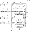
- Fig. 8 shows a circuit block diagram illustrating the outline of an electronic circuit provided in the inspection system 1.
- a controller 20 may be composed of a CPU and a memory; the blocks inside the controller 20 shown in Fig. 8 can be configured by executing software installed in the CPU.
- Detection output from the X-ray sensor 13 can be converted into digital signals at an A/D converter 21a and sent to a line data acquisition section 23 of the controller 20 via an input interface 22a.
- density data detected at the X-ray detection line of the X-ray sensor 13 can be acquired on a line-by-line basis.
- the density data for each line acquired at the line data acquisition section 23 can be sent to and accumulated at a first image data generating section 24, thereby generating a first image data 27 composed of display-sized density data.
- Detection output from the optical sensor 15 can be converted into digital signals at an A/D converter 21b and sent to a line data acquisition section 25 of the controller 20 via an input interface 22b.
- a line data acquisition section 25 density data detected at the light detection line of the optical sensor 15 can be acquired on a line-by-line basis.
- the density data for each line acquired at the line data acquisition section 25 can be sent to and accumulated at a second image data generating section 26, thereby generating a second image data 28 composed of display-sized density data.
- the first image data 27 generated at the first image data generating section 24 as a density image from the X-ray detection output can be sent to a judgment section 31, an image synthesis section 32 and a display switching section 35.
- the second image data 28 generated at the second image data generating section 26 as a density image from the light detection output can also be sent to the judgment section 31, the image synthesis section 32 and the display switching section 35.
- the judgment section 31 and the image synthesis section 32 allow data interchanges between each other.
- Detection output from the position sensor 18 can be converted into digital signals at an A/D converter 21c and sent to the judgment section 31 and the image synthesis section 32 as timing signals 29 via an input interface 22c.
- the first image data 27 and the second image data 28 are combined together.
- Combined image data 33 obtained by combining two types of image data can be sent to the display switching section 35.
- the combined image data 33 can also be sent to the judgment section 31.
- the display switching section 35 can be operable to switch by operating one of the operation buttons on the display panel.
- the combined image data 33 or the first image data 27 or the second image data 28 can be chosen by the display switching section 35 and sent to a display driver 34 via an output interface 22d.
- the display unit 19 can be driven by the display driver 34 so that the screen of the display panel can display an image based on the combined image data 33. Alternatively, the screen can display an image based on the first image data 27 or an image based on the second image data 28.
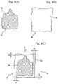
- the package W1 shown in Fig. 9(C) is formed by enclosing a content Wa in a wrapping Wb.
- the package W1 is conveyed in the F direction by the conveyor belt 8a of the upstream conveyor mechanism 6a, passed across the gap 6c and received by the conveyor belt 8b of the downstream conveyor mechanism 6b.
- the wrapping Wb of the package W1 is a bag that is formed of a synthetic resin film that is subjected to printing and therefore cannot be optically seen through, a bag that is formed of a thin metal foil such as aluminum foil and therefore cannot be optically seen through or a bag that is formed of a laminate of a metal foil and a synthetic resin film and therefore cannot be optically seen through.
- it may be a bag enclosing a tray formed of a thin synthetic resin material.
- the content Wa of the package W1 may be snack, processed food for retort pouch, processed meat or fish or fresh food.
- the timing signal 29 obtained from the detection output is sent to the judgment section 31 and the image synthesis section 32 shown in Fig. 8 .
- the package W1 passes the gap 6c of the conveyor mechanism 6, the package W1 is irradiated with the X rays emitted from the X-ray generator 10, so that the X rays transmitted through the package W1 can be detected by the X-ray sensor 13 after passing through the cover member 44 and the light-shielding member 43 shown in Fig. 3 .
- the detection output from the X-ray sensor 13 is sent to the line data acquisition section 23 of the controller 20 shown in Fig. 8 , and the line image data are accumulated at the first image data generating section 24 to generate the first image data 27. Since the wrapping Wb of the package W1 is formed of a thin packaging material, a large amount of X rays can be transmitted. On the other hand, the thickness of the content reduces the amount of X-ray transmission.
- the first image data 27 show the density contrast of the detected amount of X rays; the first data image includes image data showing the outline of the content Wa, as illustrated in Fig. 9(A) , but does not substantially include image data showing the outline of the wrapping Wb.
- the illumination light is applied to the gap 6c from the illumination part 16.
- the illumination light passes through the cover member 44, so that the package W1 passing the gap 6c can be illuminated from below.
- the illumination light passes the package W1, and the transmitted light is reflected by the reflection member 17 and detected by the optical sensor 15.
- the detection output from the optical sensor 15 is sent to the line data acquisition section 25 of the controller 20, and the line image data are accumulated at the second image data generating section 26 to generate the second image data 28.
- the second image data 28 include an image showing the outline of the wrapping Wb, as illustrated in Fig. 9(B) , but do not include an image showing the outline of the content Wa.
- the timing signal 29 teaching the detection timing is sent to the judgment section 31 and the image synthesis section 32.
- the controller 20 has a counter which begins to measure the passage of time from the moment of receiving the timing signal 29 due to detection of the package W1. Alternatively, it may begin to count the number of lines of the line image data obtained from the X-ray sensor 13 and the line image data obtained from the optical sensor 15 from the moment of receiving the timing signal.
- the first image data 27 and the second image data 28 are acquired at the same timing based on the timing signal.
- the image data are acquired such that the image data of the content Wa included in the first image data 27 coincide in relative position with the image data of the wrapping Wb included in the second image data 28.
- the first image data 27 and the second image data 28 can be amended to correct the inclination within the X-Y coordinate plane such that the side of the package W1 in the image extends along the X direction.
- the illumination part 16 and the X-ray sensor 13 are separated from each other by the partition 42 and the light-shielding member 43, so that the illumination light emitted from the illumination part 16 is hardly detected by the X-ray sensor 13. Therefore, the illumination light can be continuously emitted from the illumination part 16 while the X rays transmitted through the package W1 are being detected by the X-ray sensor 13.
- the light passing the package W1 can be continuously detected by the optical sensor 15 with the illumination light emitted continuously during the image detection by the X-ray sensor 13, which increases the amount of data: the first image data 27 acquired by the X-ray sensor 13 and the second image data 28 acquired by the optical sensor 15 as the package W1 passes the gap 6c. It is also possible to increase the conveyance velocity of the package W1 by the conveyor mechanism 6.
- Fig. 9(C) shows a combined image data 33 produced at the image synthesis section 32.
- the combined image data 33 are produced by superposing the first image data 27 and the second image data 28 to occupy the same position based on the timing signal from the position sensor 18.
- the positional relationship between the image of the content Wa and the image of the wrapping Wb is accurately the same as in the moving package W1.
- the combined image data 33 shown in Fig. 9(C) are sent to the display driver 34 and displayed on the display screen of the display unit 19.
- the data about the relative position of the image data of the content Wa and the image data of the wrapping Wb are calculated based on the combined image data 33 produced at the image synthesis section 32.
- calculated are the minimum distance S1 between the front edge of the wrapping Wb and the content Wa, the minimum distance S2 between the rear edge of the wrapping Wb and the content Wa, the minimum distance S3 between the right edge of the wrapping Wb and the content Wa, and the minimum distance S4 between the left edge of the wrapping Wb and the content Wa.
- Whether or not a part of the content Wa is caught in a seal of the wrapping Wb can be determined by obtaining the minimum distances S1, S2, S3 and S4.
- the minimum distance S1 between the front edge of the wrapping Wb and the content Wa is smaller than a predetermined threshold, there is a high possibility that at the front edge of the wrapping Wb, a part of the content Wa is caught in a seal in which the packaging materials are bonded together, causing a seal failure.
- the relative position of the content Wa and the wrapping Wb may also be determined such that the parameters S1, S2, S3 and S4 are calculated by comparing two types of image data 27 and 28 merely on data without superposing and combining the first image data 27 and the second image data 28.
- a first group of coordinate points composed of a plurality of coordinate points indicating the outline of the content Wa included in the first image data 27 are determined on the X-Y coordinates based on the timing signal from the position sensor 18; a second group of coordinate points composed of a plurality of coordinate points indicating the outline of the wrapping Wb included in the second image data 28 are also determined on the X-Y coordinates based on the timing signal. Then, the parameters S1, S2, S3 and S4 are calculated by comparing the first group of coordinate points and the second group of coordinate points.
- the foreign body in the first image data 27 can be fetched and recognized as data different in density from the content Wa. At the judgment section 31, therefore, it is possible to determine the position and size of the foreign body.
- the positional relationship between the content Wa and the wrapping Wb can be determined and the presence of the foreign body can also be detected by using the first image data 27 and the second image data 28.
- the X-ray detection image-taking line L1 passes through the gap 6c between the upstream conveyor mechanism 6a and the downstream conveyor mechanism 6b. Therefore, a scratch on the conveyor belt of the conveyor mechanism 6 or a foreign body attached to the conveyor belt can be prevented from being captured in the first image data 27, so that the image of the scratch or foreign body will never be erroneously identified as a foreign body enclosed in the package W1.
- the light-shield member 43 or the cover member 44 has a scratch or a foreign body attached thereto, they appear as noise data always at the same position in the first image data 27 or the second image data 28, and the noise data can be removed by data correction at the image synthesis section 32 or the judgment section 31, so that they hardly cause detection errors.
- the near infrared light or the like emitted from the illumination part 16 can be applied to the package W1 and the light having passed the package W1 can be detected by the optical sensor 15 to generate the second image data 28.
- the second image data 28 can be generated with the outline of the wrapping Wb of the package W1 detected clearly and accurately.
- the display switching section 35 can be operable to switch by operating one of the operation buttons on the display panel.
- the image only of the first image data 27 or the image only of the second image data 28 can be displayed on the display screen of the display unit 19.
- the image only of the second image data 28 based on the transmitted light from the illumination part 16 can be displayed, whereby when the wrapping Wb is formed of a light transmissive packaging material, whether or not the content is caught in the seal can be determined by obtaining the optical image of the package W1.
- the image to be chosen may be replaced depending on the type of the wrapping Wb.
- the wrapping Wb is a bag that cannot be optically seen through, whether or not the content is caught in the seal or the foreign body is present can be determined by acquiring both the first image data 27 and the second image data 28 and displaying the combined image;
- the wrapping Wb is formed of a light transmissive packaging material, whether or not the content is caught in the seal or the foreign body is present can be determined from the optical image by acquiring only the second image data 28.
- the illumination light can easily be transmitted through the packaging material, even though the wrapping Wb is formed of a patterned packaging material.
- blue light is used as the illumination light, the difference in brightness between the wrapping Wb and the content Wa can be increased in the optical image to have a sharp contrast between the wrapping Wb and the content Wa.
- Fig. 5 shows an inspection system 101 in which the partition 42 is provided below the floor plate 41 and the illumination part 16 is located within the region defined by the partition 42, as in the inspection system 101 shown in Fig. 3 .
- the illumination light is emitted in the Y direction.
- a lower reflection member 45 is provided to face the light-emitting element 16b such that the illumination light can be reflected upward by the lower reflection member 45, thereby providing the light detection image-taking line L3.
- the light detection image-taking line L3 and the X-ray detection image-taking line L1 extend parallel to each other in the Z direction.
- the lower reflection member 45 is placed so as not to cross the X-ray detection image-taking line L1, whereby the lower reflection member 17 is prevented from being irradiated with strong X rays.
- the reflection member 17 is provided above the conveyor mechanism 6 such that the illumination light after passing through the gap 6c upward can be reflected in the Y direction and detected by the optical sensor 15. Also, the detection window 42c of the partition 42 is closed with the light-shielding member 43, while the opening 41a of the floor plate 41 is closed with the cover member 44.
- Fig. 6 shows an inspection system 102 according to an embodiment, in which a common substrate 46 is fixed below the floor plate 41.
- a plurality of the X-ray detection elements 13b constituting the X-ray sensor 13 that is a line sensor are arranged on the common substrate 46, and a plurality of the light-emitting elements 16b constituting the illumination part 16 are also arranged on the common substrate 46.
- a partition 47 for separating the X-ray sensor 13 and the illumination part 16 is mounted with the upper opening of the partition 47 closed with the light-shielding member 43. Also in the inspection system 102, the illumination light emitted from the illumination part 16 can hardly be detected by the X-ray sensor 13.
- Fig. 7 shows an inspection system 103 in which the X-ray sensor 13 and the illumination part 16 are placed below the conveyor mechanism 6. Although not illustrated in Fig. 7 , the X-ray sensor 13 and the illumination part 16 are separated from each other by the partition such that the illumination light from the illumination part 16 does not directly enter the X-ray sensor 13. Moreover, the X-ray sensor 13 is covered with the light-shielding member 43.
- the image-taking line L1 for detection of the X rays from the X-ray generator 10 passes through the gaps 6c and extends in the Z direction, while the light detection image-taking line L4 for imaging taking at the optical sensor 15 passes through the gap 6c but crosses the X-ray detection image-taking line L1.
- the cover member 44 is placed at the gap 6c.
- the surface of the cover member 44 lies almost in the same plane as the upper surface of the conveyor belt 8a of the upstream conveyor mechanism 6a and the upper surface of the conveyor belt 8b of the downstream conveyor mechanism 6b.
- the package W1 conveyed in the Y direction by the upstream conveyor mechanism 6a can be passed to the downstream conveyor mechanism 6b such that it slides on the surface of the cover member 44.
- the X-ray detection image-taking line L1 and the light detection image-taking line L4 cross each other in the vicinity of the surface of the cover member 44.
- the noise superposition on the X-ray sensor due to the illumination light can be suppressed.
- the above-mentioned X-ray or terahertz-wave shielding zone i.e., the inspection zone for the package W is not limited to the one separated from the outside by the X-ray shielding sheet 5; for example, it may be a closed zone enclosed with partitions, wherein the conveyance surface of the conveyor belt is almost trapezoidal with the detection parts such as the X-ray sensor 13 and the optical sensor located at an upper conveyance path of the conveyor belt and with the partitions facing downward ascending and descending parts of the conveyor belt.
Landscapes
- Physics & Mathematics (AREA)
- Life Sciences & Earth Sciences (AREA)
- General Physics & Mathematics (AREA)
- General Life Sciences & Earth Sciences (AREA)
- Geophysics (AREA)
- Health & Medical Sciences (AREA)
- Spectroscopy & Molecular Physics (AREA)
- Chemical & Material Sciences (AREA)
- Analytical Chemistry (AREA)
- Biochemistry (AREA)
- General Health & Medical Sciences (AREA)
- Immunology (AREA)
- Pathology (AREA)
- Toxicology (AREA)
- High Energy & Nuclear Physics (AREA)
- Analysing Materials By The Use Of Radiation (AREA)
- Investigating Or Analysing Materials By Optical Means (AREA)
Description
- The present invention relates to a package inspection system capable of inspecting a package with both an electromagnetic-wave detector for detecting X rays or terahertz waves and an optical detector.
- In the process of manufacturing a package containing foods, an inspection system utilizing X rays has been used. Such an inspection system has been mainly used to examine whether or not any foreign body other than foods are present in the package.
- An inspection system disclosed in
Patent Literature 1 has an X-ray foreign body detection device equipped with a conveyor belt for conveying an object to be inspected. With the conveyor belt between, the X-ray foreign body detection device has an X-ray source at the upper side and an X-ray line sensor at the lower side. The X-ray foreign body detection device also has a CCD camera for taking an external optical image of an object to be inspected. - This inspection system is configured such that specific identification information such as serial number put on an object to be inspected is obtained by taking the external optical image and a single synthesis inspection image obtained by combining the result of the X-ray inspection with the specific identification information is recorded on an accumulation/record means.
- Two further examples of inspection systems utilizing X-ray foreign body detection are disclosed in
Patent Literature 2 andPatent Literature 3. -
- Patent Literature 1: Japanese Unexamined Patent Application Publication No.
2006-208098 - Patent Literature 2: European Patent Application Publication No.
1739412 A1 - Patent Literature 3:
US Patent Application Publication No. 2006/056586 A1 - In the inspection system having both the X-ray line sensor and the CCD camera, as in
Patent Literature 1, since the external optical image is to be taken by the CCD camera, an object to be inspected has to be examined in a relatively bright place where it can be observed by the CCD camera. This increases the likelihood that light other than X rays will enter the X-ray line sensor. If too much light other than X rays is applied to the X-ray line sensor, SNR at the time of detecting X rays having passed through an object to be inspected will be worsened to deteriorate the inspection accuracy for inspection of whether or not any foreign body is present in an package. - The present invention is to solve the above-mentioned problem in the prior art and has an object to provide a package inspection system which includes an optical inspection device but makes it difficult for illumination light to enter an electromagnetic-wave detector for detecting X rays or terahertz waves.
- The present invention is about a package inspection system as claimed in
Claim 1. - In the package inspection system according to the present invention, since the light from the illumination part can be blocked by the partition, the light emitted from the illumination part can be prevented from entering the electromagnetic-wave detection part. Moreover, since the light-shielding member configured to allow passage of the X ray or terahertz wave but block or reduce the light emitted from the illumination part is placed in the incident path to the electromagnetic-wave detection part, the electromagnetic-wave detection part can detect the X ray or terahertz wave such that a sufficient detection output can be generated without being affected by the light from the illumination part.
- In the package inspection system according to the present invention, the light emitted from the illumination part and having passed the package can be detected by the optical detection part. Therefore, the outline of the package can be obtained as an image with high accuracy. If the wrapping of the package is formed of a light transmissive material, the inspection of the content or the determination of whether or not the content is caught in a seal can be performed by detecting the transmitted light with the optical detection part, without using the X ray or terahertz wave. The electromagnetic-wave detection part may be enclosed by the partition, the illumination part may be provided outside the partition, and the partition may be provided with the light-shielding member at a position facing the electromagnetic-wave detection part.
- In the present invention, the light-shielding member may contain carbon, and for example, the light-shielding member may be a carbon sheet containing carbon fibers and a binder resin. Alternatively, the light-shielding member may be formed of a PEEK (polyether ether ketone) resin.
- The light-shielding member formed of such materials has a good X-ray or terahertz-wave transmittance and is hardly deteriorated by the X ray or terahertz wave.
- In the present invention, a cover member configured to allow passage of the X ray or terahertz wave and the light emitted from the illumination part may be provided between a conveyance path of the package and the electromagnetic-wave detection part and the illumination part.
- For example, the cover member may be formed of a thermoplastic polyetherimide resin.
- In the present invention, the conveyor mechanism may have a gap through which the light emitted from the illumination part and the X ray or terahertz wave is allowed to pass.
- With this configuration, a scratch on a conveyor belt or a foreign body attached to the conveyor belt can be prevented from being detected by the electromagnetic-wave detection part or the optical detection part.
- In the present invention, since the light from the illumination part can be blocked by the partition in a package inspection zone, the light emitted from the illumination part can be prevented from entering the electromagnetic-wave detection part. Moreover, since the light-shielding member configured to allow passage of the X rays or terahertz waves but block or reduce the light emitted from the illumination part is placed in the incident path to the electromagnetic-wave detection part, the electromagnetic-wave detection part can detect the X rays or terahertz waves such that a sufficient detection output can be generated without being affected by the light from the illumination part.
- Therefore, the amount of light from the illumination part can be increased to let the optical detection part detect the light having passed the package while preventing the light from being detected by the electromagnetic-wave detection part.
-
- [
Fig. 1 ] A perspective view showing the appearance of a package inspection system not in accordance with the invention. - [
Fig. 2 ] A front view showing the internal construction of the package inspection system ofFig. 1 . - [
Fig. 3 ] A sectional view showing the arrangement of an illumination part and an electromagnetic-wave detection part. - [
Fig. 4 ] A perspective view showing the arrangement of an illumination part and an electromagnetic-wave detection part. - [
Fig. 5 ] A sectional view showing the arrangement of an illumination part and an electromagnetic-wave detection part in a package inspection system not according to the invention. - [
Fig. 6 ] A sectional view showing the arrangement of an illumination part and an electromagnetic-wave detection part in a package inspection system according to an embodiment. - [
Fig. 7 ] A front view showing the internal construction of a package inspection system not according to the invention. - [
Fig. 8 ] A circuit block diagram of an inspection system according to the present invention. - [
Fig. 9 ] Illustrations of image data acquired by an inspection system according to the present invention. - As shown in
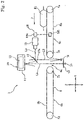
Fig. 1 , aninspection system 1 has apackage conveyance zone 2, an overlyingupper housing 3, and alower housing 4 placed below thepackage conveyance zone 2. - The
package conveyance zone 2 is formed inside anintermediate enclosure 2a. Theintermediate enclosure 2a has aninlet 4a at one end and anoutlet 4b at the other opposite end. Each of theinlet 4a and theoutlet 4b is provided with an X-ray shielding sheet 5, so that thepackage conveyance zone 2 inside theintermediate enclosure 2a becomes an electromagnetic-wave shielding zone (X-ray shielding zone). - A conveyor mechanism 6 is provided in the
package conveyance zone 2. As shown inFigs. 1 and2 , the conveyor mechanism 6 is separated into anupstream conveyor mechanism 6a and adownstream conveyor mechanism 6b, forming agap 6c at which a space is left between theupstream conveyor mechanism 6a and thedownstream conveyor mechanism 6b in the moving direction. - The
upstream conveyor mechanism 6a has anupstream roller 7a and adownstream roller 7b with aconveyor belt 8a stretched between therollers upstream roller 7a or thedownstream roller 7b is a driving roller and the other is a driven roller. Thedownstream conveyor mechanism 6b has an upstream roller 7c and adownstream roller 7d with aconveyor belt 8b stretched between therollers 7c and 7d. One of the upstream roller 7c or thedownstream roller 7d is a driving roller and the other is a driven roller. - The
upstream conveyor belt 8a is a light transmissive belt. For example, it is a transparent or semi-transparent belt made of a synthetic resin or a rubber belt having a large number of apertures regularly arranged therein. Thedownstream conveyor belt 8b may be a light transmissive one or a light non-transmissive one. - The
upstream conveyor belt 8a and thedownstream conveyor belt 8b travel around at the same speed. With theupstream conveyor belt 8a travelling around, a package W1 put on an upstream end of theupstream conveyor belt 8a is brought into the package conveyance zone (electromagnetic-wave shielding zone) 2 through theinlet 4a and conveyed at a constant speed leftward in the drawing (in the F direction). Then, after passing thegap 6c, it is received by thedownstream conveyor belt 8b and brought out of theoutlet 4b with theconveyor belt 8b travelling around. - In
Fig. 1 , the moving direction (F direction) of the package W1 is Y direction, and the direction perpendicular to the moving direction (F direction) is X direction. On the other hand, the direction vertical to the moving direction (F direction) is Z direction. - As shown in
Fig. 1 , theupper housing 3 has anupper enclosure 3a, and anX-ray generator 10 is housed in theupper enclosure 3a. TheX-ray generator 10 has an X-ray tube housed in a sealedcontainer 11. Thelower housing 4 has alower enclosure 4c, and anX-ray sensor 13 shown inFig. 2 is placed therein. - The
X-ray tube 12 is used as an electromagnetic-wave irradiation part, and theX-ray sensor 13 is used as an electromagnetic-wave detection part. However, the electromagnetic-wave irradiation part may irradiate terahertz waves, and the electromagnetic-wave detection part may be composed of elements capable of detecting terahertz waves transmitted through the package W1. - In the
upper housing 3, anoptical sensor 15 is provided as an optical detection part; in thelower housing 4, anillumination part 16 is provided. Theoptical sensor 15 is a line sensor having a plurality of light detection elements arranged linearly in the X direction perpendicular to the moving direction of the package W1 so as to form a light detection line. Theoptical sensor 15 may have either a single or a plurality of light detection lines extending in the X direction. - As shown in
Fig. 3 on an enlarge scale, afloor plate 41 formed of a stainless steel is placed below thegap 6c of the conveyor mechanism 6 in parallel to the X-Y plane. Thefloor plate 41 forms a part of a ceiling of thelower enclosure 4c. TheX-ray sensor 13 and theillumination part 16 are housed in thelower housing 4 lying below thefloor plate 41. - The
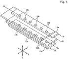
X-ray sensor 13 is a line sensor having a plurality ofX-ray detection elements 13b mounted on asensor substrate 13a, as shown inFig. 4 . The plurality ofX-ray detection elements 13b are arranged in the X direction perpendicular to the moving direction of the package W1 so as to form an X-ray detection line La. TheX-ray detection element 13b is a photodiode chip. TheX-ray sensor 13 has a single X-ray detection line La extending in the X direction but may have a plurality of the lines. - The
illumination part 16 is a line illumination device having a plurality of light-emittingelements 16b mounted on aillumination substrate 16a, as shown inFig. 4 . The plurality of light-emittingelements 16b are arranged in the X direction perpendicular to the moving direction of the package W1 so as to form an illumination line Lb. The illumination line Lb is a single line but may be composed of a plurality of lines. - The light-emitting
element 16b is a light-emitting diode (LED) which emits near infrared light or light having a blue wavelength. - As shown in
Fig. 3 , apartition 42 formed of a stainless steel is placed beneath thefloor plate 41. Thepartition 42 is a single bent member having asupport plate 42a and aside plate 42b, and theillumination substrate 16a of theillumination part 16 is fixed on thesupport plate 42a. Theside plate 42b is joined to the lower surface of thefloor plate 41 without leaving any space. Theillumination part 16 is located within the region defined by thepartition 42, while theX-ray sensor 13 is located outside thepartition 42 and below thesupport plate 42a. - The
support plate 42a of thepartition 42 has adetection window 42c above theX-ray sensor 13, and thisdetection window 42c is closed with a light-shieldingmember 43. The light-shieldingmember 43 is a plate or sheet and formed of a material that allows passage of the X rays but is capable of blocking the illumination light emitted from theillumination part 16 or reducing the transmittance of the illumination light. In order to endure long-term use, particularly, it is preferably formed of a material that is hardly deteriorated by X rays. - As the material that is hardly deteriorated by X rays, it is preferable to use a sheet containing carbon. For example, it may be a carbon sheet having carbon fibers fixed with a binder resin, a carbon sheet having a woven or nonwoven fabric of carbon fibers reinforced with a binder resin, or a carbon sheet containing a carbon material such as carbon black in a resin. Since the carbon can convert the energy of X rays into heat and dissipate the heat, it can withstand long-term irradiation of X rays.
- It is also possible to use a PEEK resin (polyether ether ketone resin) as the material that is hardly deteriorated by X rays. Since the PEEK resin is a thermoplastic resin that can be easily formed into a sheet or plate and is super heat-resistant, it can withstand long-term irradiation of X rays.
- As shown in
Fig. 3 , thefloor plate 41 has anopening 41a, and theX-ray detection elements 13b of theX-ray sensor 13 and the light-emittingelements 16b of theillumination part 16 are located beneath theopening 41a. Theopening 41a is closed with acover member 44. Thecover member 44 is formed of a material that allows passage of both the light emitted from theillumination part 16 and the X rays but is hardly deteriorated by long-term irradiation of X rays. - For example, the
cover member 44 is formed of a ULTEM resin (registered trademark) that is an amorphous thermoplastic polyetherimide resin. With thecover member 44, dirt or dust can be prevented from falling on the region where theillumination part 16 is located or the region where the light-shieldingmember 43 is located. - In
Fig. 2 , the centerline of the X-ray detection area in which X rays can be detected by the X-ray sensor 13 (X-ray detection image-taking line) is indicated by L1. The X-ray detection image-taking line (electromagnetic-wave detection image-taking line) L1 is a line joining the center of theX-ray generator 10 and the center of theX-ray sensor 13. Moreover, the X-ray detection image-taking line represents a detection plane parallel to the X-Z plane rising vertically from the X-ray detection line of theX-ray sensor 13 being a line sensor, and therefore can be restated as X-ray detection image-taking plane. The X-ray detection image-taking line L1 of theX-ray sensor 13 passes through thegap 6c of the conveyor mechanism 6 and extends in the Z direction perpendicular to the Y direction being the moving direction of the package W1. - In
Fig. 2 , the centerline of the light detection area in which light can be detected by the optical sensor 15 (light detection image-taking line) is indicated by L2 and L3. The light detection image-taking line L2 and L3 is a line joining the center of theoptical sensor 15 and the center of theillumination part 16. Moreover, the light detection image-taking line L2 and L3 represents a detection plane extending from the light detection line of theoptical sensor 15 with a depth in the X direction, and therefore can be restated as light detection image-taking plane. - As shown in
Fig. 2 , areflection member 17 is provided above the conveyor mechanism 6. Thereflection surface 17a of thereflection member 17 is inclined 45 degrees with respect to the X-Z plane. The light detection image-taking line L3 of theoptical sensor 15, which extends parallel to the Y direction, is bent downward by thereflection surface 17a of thereflection member 17 and becomes the light detection image-taking line L2. That is, the illumination light emitted from theillumination part 16 passes the package W1 passing above thegap 6c and is reflected by thereflection surface 17a and received by theoptical sensor 15. - The
X-ray sensor 13 and theillumination part 16 are closely arranged beneath the conveyor mechanism 6, and the X-ray detection image-taking line L1 and the light detection image-taking line L2 are arranged parallel to each other without coinciding in thegap 6c of the conveyor mechanism 6. - In the
inspection system 1 shown inFig. 2 , since the X-ray detection image-taking line L1 and the light detection image-taking line L2 run through thesame gap 6c, optical image data due to detection by theoptical sensor 15 can be obtained at the same conditions as image data that can be obtained by applying X rays to the package W1 passing thegap 6c. - Moreover, since the
reflection member 17 is placed so as not to cross the X-ray detection image-taking line L1, thereflection member 17 can be certainly prevented from being deteriorated by the irradiation of the X rays. - As shown in
Fig. 2 , aposition sensor 18 is provided in theupstream conveyor mechanism 6a. Theposition sensor 18 is an optical sensor composed of a light-emittingpart 18a and a light-receivingpart 18b facing each other. With the conveyance path of the package W1 between, the light-emittingpart 18a is placed at the upper or lower side thereof, and the light-receivingpart 18b faces it at the other side thereof. It should be noted that if theupstream conveyor belt 8a is not a light transmissive one, the light-emittingpart 18a and the light-receivingpart 18b may face each other in the X direction so as to detect the package W lying on the conveyance surface of theconveyor belt 8a. - As shown in
Fig. 1 , adisplay unit 19 and a control panel are provided at the front part of theupper enclosure 3a constituting theupper housing 3. Thedisplay unit 19 may be composed of a display panel such as color liquid crystal panel and its driving circuit. Various types of operation buttons are arranged on the control panel. -
Fig. 8 shows a circuit block diagram illustrating the outline of an electronic circuit provided in theinspection system 1. - A
controller 20 may be composed of a CPU and a memory; the blocks inside thecontroller 20 shown inFig. 8 can be configured by executing software installed in the CPU. - Detection output from the
X-ray sensor 13 can be converted into digital signals at an A/D converter 21a and sent to a linedata acquisition section 23 of thecontroller 20 via aninput interface 22a. At the linedata acquisition section 23, density data detected at the X-ray detection line of theX-ray sensor 13 can be acquired on a line-by-line basis. The density data for each line acquired at the linedata acquisition section 23 can be sent to and accumulated at a first imagedata generating section 24, thereby generating afirst image data 27 composed of display-sized density data. - Detection output from the
optical sensor 15 can be converted into digital signals at an A/D converter 21b and sent to a linedata acquisition section 25 of thecontroller 20 via aninput interface 22b. At the linedata acquisition section 25, density data detected at the light detection line of theoptical sensor 15 can be acquired on a line-by-line basis. The density data for each line acquired at the linedata acquisition section 25 can be sent to and accumulated at a second imagedata generating section 26, thereby generating asecond image data 28 composed of display-sized density data. - As shown in
Fig. 8 , thefirst image data 27 generated at the first imagedata generating section 24 as a density image from the X-ray detection output can be sent to ajudgment section 31, animage synthesis section 32 and adisplay switching section 35. Thesecond image data 28 generated at the second imagedata generating section 26 as a density image from the light detection output can also be sent to thejudgment section 31, theimage synthesis section 32 and thedisplay switching section 35. Thejudgment section 31 and theimage synthesis section 32 allow data interchanges between each other. - Detection output from the
position sensor 18 can be converted into digital signals at an A/D converter 21c and sent to thejudgment section 31 and theimage synthesis section 32 as timing signals 29 via aninput interface 22c. - At the
image synthesis section 32, thefirst image data 27 and thesecond image data 28 are combined together.Combined image data 33 obtained by combining two types of image data can be sent to thedisplay switching section 35. The combinedimage data 33 can also be sent to thejudgment section 31. - The
display switching section 35 can be operable to switch by operating one of the operation buttons on the display panel. The combinedimage data 33 or thefirst image data 27 or thesecond image data 28 can be chosen by thedisplay switching section 35 and sent to adisplay driver 34 via anoutput interface 22d. Thedisplay unit 19 can be driven by thedisplay driver 34 so that the screen of the display panel can display an image based on the combinedimage data 33. Alternatively, the screen can display an image based on thefirst image data 27 or an image based on thesecond image data 28. - The inspection procedure of the package W1 using the
inspection system 1 will be described hereinbelow. - The package W1 shown in
Fig. 9(C) is formed by enclosing a content Wa in a wrapping Wb. In theinspection system 1, as shown inFig. 2 , the package W1 is conveyed in the F direction by theconveyor belt 8a of theupstream conveyor mechanism 6a, passed across thegap 6c and received by theconveyor belt 8b of thedownstream conveyor mechanism 6b. - The wrapping Wb of the package W1 is a bag that is formed of a synthetic resin film that is subjected to printing and therefore cannot be optically seen through, a bag that is formed of a thin metal foil such as aluminum foil and therefore cannot be optically seen through or a bag that is formed of a laminate of a metal foil and a synthetic resin film and therefore cannot be optically seen through. Alternatively, it may be a bag enclosing a tray formed of a thin synthetic resin material.
- The content Wa of the package W1 may be snack, processed food for retort pouch, processed meat or fish or fresh food.
- When the package W1 being conveyed by the conveyor mechanism 6 passes the
position sensor 18, thetiming signal 29 obtained from the detection output is sent to thejudgment section 31 and theimage synthesis section 32 shown inFig. 8 . - When the package W1 passes the
gap 6c of the conveyor mechanism 6, the package W1 is irradiated with the X rays emitted from theX-ray generator 10, so that the X rays transmitted through the package W1 can be detected by theX-ray sensor 13 after passing through thecover member 44 and the light-shieldingmember 43 shown inFig. 3 . - The detection output from the
X-ray sensor 13 is sent to the linedata acquisition section 23 of thecontroller 20 shown inFig. 8 , and the line image data are accumulated at the first imagedata generating section 24 to generate thefirst image data 27. Since the wrapping Wb of the package W1 is formed of a thin packaging material, a large amount of X rays can be transmitted. On the other hand, the thickness of the content reduces the amount of X-ray transmission. Thefirst image data 27 show the density contrast of the detected amount of X rays; the first data image includes image data showing the outline of the content Wa, as illustrated inFig. 9(A) , but does not substantially include image data showing the outline of the wrapping Wb. - Also, the illumination light is applied to the
gap 6c from theillumination part 16. The illumination light passes through thecover member 44, so that the package W1 passing thegap 6c can be illuminated from below. The illumination light passes the package W1, and the transmitted light is reflected by thereflection member 17 and detected by theoptical sensor 15. - The detection output from the
optical sensor 15 is sent to the linedata acquisition section 25 of thecontroller 20, and the line image data are accumulated at the second imagedata generating section 26 to generate thesecond image data 28. Since the wrapping Wb of the package W1 is formed of a light non-transmissive packaging material, thesecond image data 28 include an image showing the outline of the wrapping Wb, as illustrated inFig. 9(B) , but do not include an image showing the outline of the content Wa. - When the package W1 being conveyed in the F direction by the conveyor mechanism 6 is detected by the
position sensor 18, thetiming signal 29 teaching the detection timing is sent to thejudgment section 31 and theimage synthesis section 32. - The
controller 20 has a counter which begins to measure the passage of time from the moment of receiving thetiming signal 29 due to detection of the package W1. Alternatively, it may begin to count the number of lines of the line image data obtained from theX-ray sensor 13 and the line image data obtained from theoptical sensor 15 from the moment of receiving the timing signal. - At the
judgment section 31 and theimage synthesis section 32, thefirst image data 27 and thesecond image data 28 are acquired at the same timing based on the timing signal. In other words, the image data are acquired such that the image data of the content Wa included in thefirst image data 27 coincide in relative position with the image data of the wrapping Wb included in thesecond image data 28. - It should be noted that when the package W1 on the conveyor mechanism 6 is being conveyed with its side edge inclined with respect to the X direction, the
first image data 27 and thesecond image data 28 can be amended to correct the inclination within the X-Y coordinate plane such that the side of the package W1 in the image extends along the X direction. - As shown in
Fig. 3 , theillumination part 16 and theX-ray sensor 13 are separated from each other by thepartition 42 and the light-shieldingmember 43, so that the illumination light emitted from theillumination part 16 is hardly detected by theX-ray sensor 13. Therefore, the illumination light can be continuously emitted from theillumination part 16 while the X rays transmitted through the package W1 are being detected by theX-ray sensor 13. - The light passing the package W1 can be continuously detected by the
optical sensor 15 with the illumination light emitted continuously during the image detection by theX-ray sensor 13, which increases the amount of data: thefirst image data 27 acquired by theX-ray sensor 13 and thesecond image data 28 acquired by theoptical sensor 15 as the package W1 passes thegap 6c. It is also possible to increase the conveyance velocity of the package W1 by the conveyor mechanism 6. -
Fig. 9(C) shows a combinedimage data 33 produced at theimage synthesis section 32. The combinedimage data 33 are produced by superposing thefirst image data 27 and thesecond image data 28 to occupy the same position based on the timing signal from theposition sensor 18. In the combinedimage data 33, the positional relationship between the image of the content Wa and the image of the wrapping Wb is accurately the same as in the moving package W1. After the selection by thedisplay switching section 35, the combinedimage data 33 shown inFig. 9(C) are sent to thedisplay driver 34 and displayed on the display screen of thedisplay unit 19. - At the
judgment section 31 of thecontroller 20, the data about the relative position of the image data of the content Wa and the image data of the wrapping Wb are calculated based on the combinedimage data 33 produced at theimage synthesis section 32. In the example shown inFig. 9(C) , calculated are the minimum distance S1 between the front edge of the wrapping Wb and the content Wa, the minimum distance S2 between the rear edge of the wrapping Wb and the content Wa, the minimum distance S3 between the right edge of the wrapping Wb and the content Wa, and the minimum distance S4 between the left edge of the wrapping Wb and the content Wa. - Whether or not a part of the content Wa is caught in a seal of the wrapping Wb can be determined by obtaining the minimum distances S1, S2, S3 and S4. In the example shown in
Fig. 9(C) , it is determined that since the minimum distance S1 between the front edge of the wrapping Wb and the content Wa is smaller than a predetermined threshold, there is a high possibility that at the front edge of the wrapping Wb, a part of the content Wa is caught in a seal in which the packaging materials are bonded together, causing a seal failure. - At the
judgment section 31 of thecontroller 20, the relative position of the content Wa and the wrapping Wb may also be determined such that the parameters S1, S2, S3 and S4 are calculated by comparing two types ofimage data first image data 27 and thesecond image data 28. - For example, at the
judgment section 31, a first group of coordinate points composed of a plurality of coordinate points indicating the outline of the content Wa included in thefirst image data 27 are determined on the X-Y coordinates based on the timing signal from theposition sensor 18; a second group of coordinate points composed of a plurality of coordinate points indicating the outline of the wrapping Wb included in thesecond image data 28 are also determined on the X-Y coordinates based on the timing signal. Then, the parameters S1, S2, S3 and S4 are calculated by comparing the first group of coordinate points and the second group of coordinate points. - If a foreign body other than the normal content Wa, e.g., a piece of metal is present in the wrapping Wb of the package W1, furthermore, the foreign body in the
first image data 27 can be fetched and recognized as data different in density from the content Wa. At thejudgment section 31, therefore, it is possible to determine the position and size of the foreign body. In theinspection system 1, accordingly, the positional relationship between the content Wa and the wrapping Wb can be determined and the presence of the foreign body can also be detected by using thefirst image data 27 and thesecond image data 28. - In the
inspection system 1, the X-ray detection image-taking line L1 passes through thegap 6c between theupstream conveyor mechanism 6a and thedownstream conveyor mechanism 6b. Therefore, a scratch on the conveyor belt of the conveyor mechanism 6 or a foreign body attached to the conveyor belt can be prevented from being captured in thefirst image data 27, so that the image of the scratch or foreign body will never be erroneously identified as a foreign body enclosed in the package W1. - It should be noted that even if the light-
shield member 43 or thecover member 44 has a scratch or a foreign body attached thereto, they appear as noise data always at the same position in thefirst image data 27 or thesecond image data 28, and the noise data can be removed by data correction at theimage synthesis section 32 or thejudgment section 31, so that they hardly cause detection errors. - Moreover, since the light detection image-taking line L2 passes through the
gap 6c, the near infrared light or the like emitted from theillumination part 16 can be applied to the package W1 and the light having passed the package W1 can be detected by theoptical sensor 15 to generate thesecond image data 28. Through the use of the transmitted light, thesecond image data 28 can be generated with the outline of the wrapping Wb of the package W1 detected clearly and accurately. - In the
inspection system 1, thedisplay switching section 35 can be operable to switch by operating one of the operation buttons on the display panel. By this switching, the image only of thefirst image data 27 or the image only of thesecond image data 28 can be displayed on the display screen of thedisplay unit 19. Particularly, the image only of thesecond image data 28 based on the transmitted light from theillumination part 16 can be displayed, whereby when the wrapping Wb is formed of a light transmissive packaging material, whether or not the content is caught in the seal can be determined by obtaining the optical image of the package W1. - In the
inspection system 1, accordingly, the image to be chosen may be replaced depending on the type of the wrapping Wb. For example, when the wrapping Wb is a bag that cannot be optically seen through, whether or not the content is caught in the seal or the foreign body is present can be determined by acquiring both thefirst image data 27 and thesecond image data 28 and displaying the combined image; when the wrapping Wb is formed of a light transmissive packaging material, whether or not the content is caught in the seal or the foreign body is present can be determined from the optical image by acquiring only thesecond image data 28. - When only the
second image data 28 are acquired and only the optical image is used to determine whether or not something is caught or the foreign body is present, if near infrared light is used as the illumination light emitted from theillumination part 16, the illumination light can easily be transmitted through the packaging material, even though the wrapping Wb is formed of a patterned packaging material. On the other hand, if blue light is used as the illumination light, the difference in brightness between the wrapping Wb and the content Wa can be increased in the optical image to have a sharp contrast between the wrapping Wb and the content Wa. - Hereinbelow, other examples of the inspection system will be described with reference to
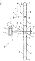
Figs. 5 to 7 . In the following, the components different from those in theinspection system 1 according to the first embodiment will be mainly described. On the other hand, the components similar to those in theinspection system 1 according to the first embodiment will be denoted by the same reference signs, and detailed description will be omitted. -
Fig. 5 shows aninspection system 101 in which thepartition 42 is provided below thefloor plate 41 and theillumination part 16 is located within the region defined by thepartition 42, as in theinspection system 101 shown inFig. 3 . From the light-emittingelement 16b of theillumination part 16, the illumination light is emitted in the Y direction. Inside thepartition 42, alower reflection member 45 is provided to face the light-emittingelement 16b such that the illumination light can be reflected upward by thelower reflection member 45, thereby providing the light detection image-taking line L3. Through thegap 6c, the light detection image-taking line L3 and the X-ray detection image-taking line L1 extend parallel to each other in the Z direction. Thelower reflection member 45 is placed so as not to cross the X-ray detection image-taking line L1, whereby thelower reflection member 17 is prevented from being irradiated with strong X rays. - Also in the
inspection system 101 as inFig. 2 , thereflection member 17 is provided above the conveyor mechanism 6 such that the illumination light after passing through thegap 6c upward can be reflected in the Y direction and detected by theoptical sensor 15. Also, thedetection window 42c of thepartition 42 is closed with the light-shieldingmember 43, while theopening 41a of thefloor plate 41 is closed with thecover member 44. -
Fig. 6 shows aninspection system 102 according to an embodiment, in which acommon substrate 46 is fixed below thefloor plate 41. A plurality of theX-ray detection elements 13b constituting theX-ray sensor 13 that is a line sensor are arranged on thecommon substrate 46, and a plurality of the light-emittingelements 16b constituting theillumination part 16 are also arranged on thecommon substrate 46. - On the
common substrate 46, apartition 47 for separating theX-ray sensor 13 and theillumination part 16 is mounted with the upper opening of thepartition 47 closed with the light-shieldingmember 43. Also in theinspection system 102, the illumination light emitted from theillumination part 16 can hardly be detected by theX-ray sensor 13. -
Fig. 7 shows aninspection system 103 in which theX-ray sensor 13 and theillumination part 16 are placed below the conveyor mechanism 6. Although not illustrated inFig. 7 , theX-ray sensor 13 and theillumination part 16 are separated from each other by the partition such that the illumination light from theillumination part 16 does not directly enter theX-ray sensor 13. Moreover, theX-ray sensor 13 is covered with the light-shieldingmember 43. - The image-taking line L1 for detection of the X rays from the
X-ray generator 10 passes through thegaps 6c and extends in the Z direction, while the light detection image-taking line L4 for imaging taking at theoptical sensor 15 passes through thegap 6c but crosses the X-ray detection image-taking line L1. - The
cover member 44 is placed at thegap 6c. The surface of thecover member 44 lies almost in the same plane as the upper surface of theconveyor belt 8a of theupstream conveyor mechanism 6a and the upper surface of theconveyor belt 8b of thedownstream conveyor mechanism 6b. The package W1 conveyed in the Y direction by theupstream conveyor mechanism 6a can be passed to thedownstream conveyor mechanism 6b such that it slides on the surface of thecover member 44. - The X-ray detection image-taking line L1 and the light detection image-taking line L4 cross each other in the vicinity of the surface of the
cover member 44. - According to the present invention, therefore, when both the
illumination part 16 and theX-ray sensor 13 are placed in the X-ray or terahertz-wave shielding zone, i.e., the inspection zone for the package W, separated from the outside by the X-ray shielding sheet 5, as shown inFig. 1 , the noise superposition on the X-ray sensor due to the illumination light can be suppressed. - The above-mentioned X-ray or terahertz-wave shielding zone, i.e., the inspection zone for the package W is not limited to the one separated from the outside by the X-ray shielding sheet 5; for example, it may be a closed zone enclosed with partitions, wherein the conveyance surface of the conveyor belt is almost trapezoidal with the detection parts such as the
X-ray sensor 13 and the optical sensor located at an upper conveyance path of the conveyor belt and with the partitions facing downward ascending and descending parts of the conveyor belt. -
- 1, 101, 102, 103
- Inspection System
- 2
- Package Conveyance Zone
- 6
- Conveyor Mechanism
- 6a
- Upstream Conveyor Mechanism
- 6b
- Downstream Conveyor Mechanism
- 6c
- Gap
- 10
- X-ray Generator (Irradiation Part)
- 13
- X-ray Sensor (Electromagnetic-wave Detection part)
- 13a
- Sensor Substrate
- 13b
- X-ray Detection Element
- 15
- Optical Sensor (Optical Detection Part)
- 16
- Illumination Part
- 16a
- Illumination Substrate
- 16b
- Light-emitting Element
- 18
- Position Sensor
- 19
- Display Unit
- 20
- Controller
- 24
- First Image Data Generating Section
- 26
- Second Image Data Generating Section
- 31
- Judgment Section
- 32
- Image Synthesis Section
- 41
- Floor Plate
- 42
- Partition
- 43
- Light-shielding Member
- 44
- Cover Member
- 47
- Partition
- W1
- Package
- Wa
- Content
- Wb
- Wrapping
Claims (8)
- A package inspection system (1) comprising: a conveyor mechanism (6) for conveying a package (W1) having a content in a wrapping; an irradiation part (10) for irradiating the package with an X ray or a terahertz wave; an electromagnetic-wave detection part (13) for detecting the X ray or terahertz wave transmitted through the package; an illumination part (16) for illuminating the package with a light; and an optical detection part (15) for taking an optical image of the package, a partition (42) being provided between the electromagnetic-wave detection part and the illumination part, characterized in that: the partition has a light-shielding member (43) configured to allow passage of the X ray or terahertz wave but block or reduce the light emitted from the illumination part, at least in a path through which the X ray or terahertz wave enters the electromagnetic-wave detection part, thereby to generate a detection output unaffected by light from the illumination part; and the irradiation part and the optical detection part are provided at one side of a conveyance path of the package, and the illumination part and the electromagnetic-wave detection part are provided at the other side thereof; wherein a common substrate (46) is provided below a floor plate (41) which is below the conveyor mechanism, a plurality of X-ray detection elements 13b constituting said electromagnetic-wave detection part 13 that is a line sensor are arranged on the common substrate 46, and a plurality of light-emitting elements 16b constituting the illumination part 16 are also arranged on the common substrate 46, and wherein the partition is mounted on the common substrate and has an opening which is closed by said light-shielding member.
- A package inspection system according to claim 1, wherein the electromagnetic-wave detection part is enclosed by the partition, the illumination part is provided outside the partition, and the partition is provided with the light-shielding member at a position facing the electromagnetic-wave detection part.
- A package inspection system according to any of claims 1 to 2, wherein the light-shielding member contains carbon.
- A package inspection system according to claim 3, wherein the light-shielding member is a carbon sheet containing carbon fibers and a binder resin.
- A package inspection system according to anyone of claims 1 to 2, wherein the light-shielding member is formed of a PEEK (polyether ether ketone) resin.
- A package inspection system according to claim 1, wherein a cover member (44) configured to allow passage of the X ray or terahertz wave and the light emitted from the illumination part is provided between a conveyance path of the package and the electromagnetic-wave detection part and the illumination part.
- A package inspection system according to claim 6, wherein the cover member is formed of a thermoplastic polyetherimide resin.
- A package inspection system according to any of claims 1 to 7, wherein the conveyor mechanism has a gap (6c) through which the light emitted from the illumination part and the X ray or terahertz wave is allowed to pass.
Applications Claiming Priority (1)
| Application Number | Priority Date | Filing Date | Title |
|---|---|---|---|
| PCT/JP2013/076984 WO2015049765A1 (en) | 2013-10-03 | 2013-10-03 | Package inspection device |
Publications (5)
| Publication Number | Publication Date |
|---|---|
| EP3045897A1 EP3045897A1 (en) | 2016-07-20 |
| EP3045897A4 EP3045897A4 (en) | 2017-05-24 |
| EP3045897B1 EP3045897B1 (en) | 2019-07-03 |
| EP3045897B8 EP3045897B8 (en) | 2019-08-14 |
| EP3045897B2 true EP3045897B2 (en) | 2022-12-28 |
Family
ID=52778375
Family Applications (1)
| Application Number | Title | Priority Date | Filing Date |
|---|---|---|---|
| EP13889357.3A Active EP3045897B2 (en) | 2013-10-03 | 2013-10-03 | Package inspection device |
Country Status (5)
| Country | Link |
|---|---|
| US (1) | US9733384B2 (en) |
| EP (1) | EP3045897B2 (en) |
| JP (1) | JP5720028B1 (en) |
| CN (1) | CN104718447B (en) |
| WO (1) | WO2015049765A1 (en) |
Families Citing this family (21)
| Publication number | Priority date | Publication date | Assignee | Title |
|---|---|---|---|---|
| JP6335499B2 (en) * | 2013-12-13 | 2018-05-30 | 株式会社イシダ | Optical inspection device |
| WO2016165828A1 (en) * | 2015-04-15 | 2016-10-20 | Yxlon International Gmbh | Method for checking an electronic component |
| JP6787936B2 (en) | 2015-06-30 | 2020-11-18 | イリノイ トゥール ワークス インコーポレイティド | In-line X-ray measuring device and method |
| CA2952775C (en) * | 2015-12-23 | 2020-04-14 | Raysecur Inc. | Mail screening apparatus |
| JP2018004365A (en) * | 2016-06-30 | 2018-01-11 | ローム株式会社 | Reflection type detector |
| CN106185226B (en) * | 2016-09-29 | 2019-05-03 | 同方威视技术股份有限公司 | Combined conveying device for detection channel of container inspection system, and container inspection system |
| WO2018131149A1 (en) * | 2017-01-13 | 2018-07-19 | 株式会社ニコン | Powder storing container and method for inspecting foreign material |
| CN107193051A (en) * | 2017-07-07 | 2017-09-22 | 深圳翠博微系统有限公司 | A kind of Terahertz conveyer belt detecting system |
| CN109188554B (en) * | 2018-08-13 | 2021-05-25 | 北京逸智联科技有限公司 | Cosmetic packaging quality detection system and detection method |
| KR102153450B1 (en) * | 2018-12-28 | 2020-09-08 | (주)미래컴퍼니 | Inspection apparatus using terahertz wave |
| KR20200082002A (en) * | 2018-12-28 | 2020-07-08 | (주)미래컴퍼니 | Inspection apparatus using terahertz wave |
| JP6783347B1 (en) * | 2019-05-27 | 2020-11-11 | Ckd株式会社 | Inspection equipment, packaging sheet manufacturing equipment and packaging sheet manufacturing method |
| JP6752941B1 (en) * | 2019-06-17 | 2020-09-09 | Ckd株式会社 | Inspection equipment, packaging material manufacturing equipment and packaging material manufacturing method |
| CN110632676B (en) * | 2019-09-05 | 2021-01-12 | 福建恒安集团有限公司 | High polymer material loss detection mechanism and detection method on hygienic product production line |
| JP7382228B2 (en) * | 2019-12-26 | 2023-11-16 | ニッタ株式会社 | conveyor belt |
| KR20230056623A (en) | 2020-08-26 | 2023-04-27 | 하마마츠 포토닉스 가부시키가이샤 | foreign object inspection device |
| US11284018B1 (en) * | 2020-09-15 | 2022-03-22 | Applied Materials, Inc. | Smart camera substrate |
| US11573175B2 (en) | 2020-12-22 | 2023-02-07 | Industrial Technology Research Institute | Calibration assembly for scan device and calibration system |
| US12101581B2 (en) | 2022-04-04 | 2024-09-24 | Tyco Fire & Security Gmbh | Method and system for recording a mail screening process |
| JP2024133851A (en) * | 2023-03-20 | 2024-10-03 | 株式会社イシダ | X-ray inspection equipment |
| CN116461801B (en) * | 2023-04-24 | 2025-06-20 | 河北龙之养饮料有限公司 | Packing box filling material detection device and method |
Family Cites Families (29)
| Publication number | Priority date | Publication date | Assignee | Title |
|---|---|---|---|---|
| JPS5953500B2 (en) | 1978-06-06 | 1984-12-25 | 株式会社東芝 | X-ray fluoroscopy equipment |
| JPS5817544A (en) | 1981-07-23 | 1983-02-01 | Matsushita Electric Ind Co Ltd | Manufacture of magnetic recording medium |
| JPS5817544U (en) * | 1981-07-27 | 1983-02-03 | ソフテツクス株式会社 | Television device for observing soft X-ray images and solid images |
| JPH0252246A (en) | 1988-08-15 | 1990-02-21 | Tokyo Electron Ltd | X-ray inspection device |
| JPH06281598A (en) | 1991-07-26 | 1994-10-07 | Motoronikusu:Kk | Apparatus and method for simultaneously displaying x-ray image and optical image of multilayered work |
| JPH09127017A (en) | 1995-10-31 | 1997-05-16 | Shimazu Mekutemu Kk | X-ray foreign-matter inspection apparatus with metering function and product inspection method using the apparatus |
| US5901198A (en) * | 1997-10-10 | 1999-05-04 | Analogic Corporation | Computed tomography scanning target detection using target surface normals |
| US6324253B1 (en) * | 1998-08-26 | 2001-11-27 | Yuyama Mfg. Co., Ltd. | Tablet inspection apparatus |
| JP2000135268A (en) | 1998-08-26 | 2000-05-16 | Yuyama Seisakusho:Kk | Tablet testing device |
| DE69929027T2 (en) | 1998-12-28 | 2006-08-24 | Kabushiki Kaisha Toshiba, Kawasaki | Radiation detector device |
| JP2002168803A (en) * | 2000-11-30 | 2002-06-14 | Anritsu Corp | X-ray foreign matter detector |
| US6510195B1 (en) | 2001-07-18 | 2003-01-21 | Koninklijke Philips Electronics, N.V. | Solid state x-radiation detector modules and mosaics thereof, and an imaging method and apparatus employing the same |
| JP2006084275A (en) | 2004-09-15 | 2006-03-30 | Hitachi Ltd | Method and apparatus for detecting explosives, etc. |
| JP4536533B2 (en) | 2005-01-26 | 2010-09-01 | アンリツ産機システム株式会社 | X-ray foreign object detection device |
| US20060185087A1 (en) * | 2005-02-08 | 2006-08-24 | Coppens Daniel D | Rigid patient support element for low patient skin damage when used in a radiation therapy environment |
| JP4730526B2 (en) | 2005-06-27 | 2011-07-20 | 独立行政法人理化学研究所 | Inclusion inspection device |
| DE102006033497B4 (en) | 2006-07-19 | 2014-05-22 | Siemens Aktiengesellschaft | Radiation detector for X-rays or gamma rays and process for its preparation |
| JP5358073B2 (en) * | 2007-08-10 | 2013-12-04 | ライオンエンジニアリング株式会社 | Package inspection system and inspection method |
| US8489232B2 (en) | 2008-09-30 | 2013-07-16 | Amazon Technologies, Inc. | Systems and methods for receiving shipment parcels |
| JP5118661B2 (en) | 2009-03-25 | 2013-01-16 | 浜松ホトニクス株式会社 | X-ray imaging device |
| JP5302238B2 (en) | 2009-05-13 | 2013-10-02 | 株式会社イシダ | X-ray inspection equipment |
| EP2275871B1 (en) | 2009-07-16 | 2018-06-27 | ASML Netherlands B.V. | Position Calibration of Alignment Heads in a Multi-Head Alignment System |
| JP5408432B2 (en) | 2009-12-18 | 2014-02-05 | 横河電機株式会社 | Radiation detection apparatus and radiation detection method using this apparatus |
| JP4810665B1 (en) | 2010-05-10 | 2011-11-09 | 株式会社 システムスクエア | Optical inspection apparatus and optical inspection method |
| JP2012168128A (en) | 2011-02-16 | 2012-09-06 | Canon Inc | Radiation detection device and radiation imaging system |
| JP5453350B2 (en) * | 2011-06-23 | 2014-03-26 | 株式会社 システムスクエア | Packaging inspection equipment |
| DE202011051843U1 (en) | 2011-11-02 | 2011-11-15 | Wipotec Wiege- Und Positioniersysteme Gmbh | tester |
| JP3175930U (en) * | 2012-03-16 | 2012-06-07 | 株式会社イシダ | X-ray inspection equipment |
| JP5720029B2 (en) | 2012-10-17 | 2015-05-20 | 株式会社 システムスクエア | Packaging inspection equipment |
-
2013
- 2013-10-03 EP EP13889357.3A patent/EP3045897B2/en active Active
- 2013-10-03 CN CN201380043026.8A patent/CN104718447B/en active Active
- 2013-10-03 WO PCT/JP2013/076984 patent/WO2015049765A1/en not_active Ceased
- 2013-10-03 JP JP2014540243A patent/JP5720028B1/en active Active
- 2013-10-03 US US14/418,895 patent/US9733384B2/en active Active
Also Published As
| Publication number | Publication date |
|---|---|
| JP5720028B1 (en) | 2015-05-20 |
| CN104718447B (en) | 2017-07-28 |
| US9733384B2 (en) | 2017-08-15 |
| EP3045897A4 (en) | 2017-05-24 |
| US20160033404A1 (en) | 2016-02-04 |
| EP3045897B1 (en) | 2019-07-03 |
| EP3045897B8 (en) | 2019-08-14 |
| EP3045897A1 (en) | 2016-07-20 |
| JPWO2015049765A1 (en) | 2017-03-09 |
| WO2015049765A1 (en) | 2015-04-09 |
| CN104718447A (en) | 2015-06-17 |
Similar Documents
| Publication | Publication Date | Title |
|---|---|---|
| EP3045897B2 (en) | Package inspection device | |
| EP2887056B1 (en) | Apparatus for inspecting packaging body | |
| US12276623B2 (en) | Foreign matter inspection device | |
| JP5124226B2 (en) | Radiation detector | |
| WO2016063380A1 (en) | Package inspecting apparatus | |
| TW201623947A (en) | Transmission type defect detecting device and defect detecting method | |
| KR102866743B1 (en) | Case goods inspection system and method | |
| JP5344792B2 (en) | Measurement system and method for detecting defects in an object | |
| EP2264898B1 (en) | Optical proximity sensor | |
| JP5791101B2 (en) | Bonded plate inspection apparatus and method | |
| JP5884145B1 (en) | Inspection device using electromagnetic wave detector and optical detector | |
| JP6617238B2 (en) | Packaging inspection equipment | |
| JP4213106B2 (en) | Appearance inspection device and PTP packaging machine | |
| JP2020190441A (en) | Wrinkle inspection device, wrinkle determination device, and wrinkle inspection method | |
| JP2005164488A (en) | Tester and inspection device | |
| JP6204892B2 (en) | Moving handrail deterioration diagnosis device for passenger conveyor | |
| JP2004246171A (en) | Defect detection method and apparatus for transparent plate | |
| JP6914753B2 (en) | Package content inspection method and inspection equipment | |
| JP2018141673A (en) | Radiation detector and radiation detection apparatus | |
| JP5513582B2 (en) | Radiation detector | |
| JP2019039684A (en) | Optical inspection device and output strength adjustment method | |
| JP2006071524A (en) | Crack detector for press-molded article |
Legal Events
| Date | Code | Title | Description |
|---|---|---|---|
| PUAI | Public reference made under article 153(3) epc to a published international application that has entered the european phase |
Free format text: ORIGINAL CODE: 0009012 |
|
| 17P | Request for examination filed |
Effective date: 20150121 |
|
| AK | Designated contracting states |
Kind code of ref document: A1 Designated state(s): AL AT BE BG CH CY CZ DE DK EE ES FI FR GB GR HR HU IE IS IT LI LT LU LV MC MK MT NL NO PL PT RO RS SE SI SK SM TR |
|
| AX | Request for extension of the european patent |
Extension state: BA ME |
|
| DAX | Request for extension of the european patent (deleted) | ||
| A4 | Supplementary search report drawn up and despatched |
Effective date: 20170426 |
|
| RIC1 | Information provided on ipc code assigned before grant |
Ipc: G01N 21/90 20060101ALI20170420BHEP Ipc: G01N 23/04 20060101AFI20170420BHEP Ipc: G01N 21/3581 20140101ALI20170420BHEP |
|
| GRAP | Despatch of communication of intention to grant a patent |
Free format text: ORIGINAL CODE: EPIDOSNIGR1 |
|
| STAA | Information on the status of an ep patent application or granted ep patent |
Free format text: STATUS: GRANT OF PATENT IS INTENDED |
|
| INTG | Intention to grant announced |
Effective date: 20190207 |
|
| GRAS | Grant fee paid |
Free format text: ORIGINAL CODE: EPIDOSNIGR3 |
|
| GRAA | (expected) grant |
Free format text: ORIGINAL CODE: 0009210 |
|
| STAA | Information on the status of an ep patent application or granted ep patent |
Free format text: STATUS: THE PATENT HAS BEEN GRANTED |
|
| AK | Designated contracting states |
Kind code of ref document: B1 Designated state(s): AL AT BE BG CH CY CZ DE DK EE ES FI FR GB GR HR HU IE IS IT LI LT LU LV MC MK MT NL NO PL PT RO RS SE SI SK SM TR |
|
| REG | Reference to a national code |
Ref country code: GB Ref legal event code: FG4D |
|
| REG | Reference to a national code |
Ref country code: CH Ref legal event code: EP Ref country code: AT Ref legal event code: REF Ref document number: 1151606 Country of ref document: AT Kind code of ref document: T Effective date: 20190715 |
|
| RAP2 | Party data changed (patent owner data changed or rights of a patent transferred) |
Owner name: SYSTEM SQUARE INC. |
|
| REG | Reference to a national code |
Ref country code: IE Ref legal event code: FG4D |
|
| REG | Reference to a national code |
Ref country code: DE Ref legal event code: R096 Ref document number: 602013057525 Country of ref document: DE |
|
| REG | Reference to a national code |
Ref country code: CH Ref legal event code: PK Free format text: BERICHTIGUNG B8 |
|
| REG | Reference to a national code |
Ref country code: NL Ref legal event code: MP Effective date: 20190703 |
|
| REG | Reference to a national code |
Ref country code: LT Ref legal event code: MG4D |
|
| REG | Reference to a national code |
Ref country code: AT Ref legal event code: MK05 Ref document number: 1151606 Country of ref document: AT Kind code of ref document: T Effective date: 20190703 |
|
| PG25 | Lapsed in a contracting state [announced via postgrant information from national office to epo] |
Ref country code: LT Free format text: LAPSE BECAUSE OF FAILURE TO SUBMIT A TRANSLATION OF THE DESCRIPTION OR TO PAY THE FEE WITHIN THE PRESCRIBED TIME-LIMIT Effective date: 20190703 Ref country code: CZ Free format text: LAPSE BECAUSE OF FAILURE TO SUBMIT A TRANSLATION OF THE DESCRIPTION OR TO PAY THE FEE WITHIN THE PRESCRIBED TIME-LIMIT Effective date: 20190703 Ref country code: NL Free format text: LAPSE BECAUSE OF FAILURE TO SUBMIT A TRANSLATION OF THE DESCRIPTION OR TO PAY THE FEE WITHIN THE PRESCRIBED TIME-LIMIT Effective date: 20190703 Ref country code: PT Free format text: LAPSE BECAUSE OF FAILURE TO SUBMIT A TRANSLATION OF THE DESCRIPTION OR TO PAY THE FEE WITHIN THE PRESCRIBED TIME-LIMIT Effective date: 20191104 Ref country code: BG Free format text: LAPSE BECAUSE OF FAILURE TO SUBMIT A TRANSLATION OF THE DESCRIPTION OR TO PAY THE FEE WITHIN THE PRESCRIBED TIME-LIMIT Effective date: 20191003 Ref country code: SE Free format text: LAPSE BECAUSE OF FAILURE TO SUBMIT A TRANSLATION OF THE DESCRIPTION OR TO PAY THE FEE WITHIN THE PRESCRIBED TIME-LIMIT Effective date: 20190703 Ref country code: HR Free format text: LAPSE BECAUSE OF FAILURE TO SUBMIT A TRANSLATION OF THE DESCRIPTION OR TO PAY THE FEE WITHIN THE PRESCRIBED TIME-LIMIT Effective date: 20190703 Ref country code: AT Free format text: LAPSE BECAUSE OF FAILURE TO SUBMIT A TRANSLATION OF THE DESCRIPTION OR TO PAY THE FEE WITHIN THE PRESCRIBED TIME-LIMIT Effective date: 20190703 Ref country code: NO Free format text: LAPSE BECAUSE OF FAILURE TO SUBMIT A TRANSLATION OF THE DESCRIPTION OR TO PAY THE FEE WITHIN THE PRESCRIBED TIME-LIMIT Effective date: 20191003 Ref country code: FI Free format text: LAPSE BECAUSE OF FAILURE TO SUBMIT A TRANSLATION OF THE DESCRIPTION OR TO PAY THE FEE WITHIN THE PRESCRIBED TIME-LIMIT Effective date: 20190703 |
|
| PG25 | Lapsed in a contracting state [announced via postgrant information from national office to epo] |
Ref country code: IS Free format text: LAPSE BECAUSE OF FAILURE TO SUBMIT A TRANSLATION OF THE DESCRIPTION OR TO PAY THE FEE WITHIN THE PRESCRIBED TIME-LIMIT Effective date: 20191103 Ref country code: GR Free format text: LAPSE BECAUSE OF FAILURE TO SUBMIT A TRANSLATION OF THE DESCRIPTION OR TO PAY THE FEE WITHIN THE PRESCRIBED TIME-LIMIT Effective date: 20191004 Ref country code: LV Free format text: LAPSE BECAUSE OF FAILURE TO SUBMIT A TRANSLATION OF THE DESCRIPTION OR TO PAY THE FEE WITHIN THE PRESCRIBED TIME-LIMIT Effective date: 20190703 Ref country code: AL Free format text: LAPSE BECAUSE OF FAILURE TO SUBMIT A TRANSLATION OF THE DESCRIPTION OR TO PAY THE FEE WITHIN THE PRESCRIBED TIME-LIMIT Effective date: 20190703 Ref country code: RS Free format text: LAPSE BECAUSE OF FAILURE TO SUBMIT A TRANSLATION OF THE DESCRIPTION OR TO PAY THE FEE WITHIN THE PRESCRIBED TIME-LIMIT Effective date: 20190703 Ref country code: ES Free format text: LAPSE BECAUSE OF FAILURE TO SUBMIT A TRANSLATION OF THE DESCRIPTION OR TO PAY THE FEE WITHIN THE PRESCRIBED TIME-LIMIT Effective date: 20190703 |
|
| PG25 | Lapsed in a contracting state [announced via postgrant information from national office to epo] |
Ref country code: TR Free format text: LAPSE BECAUSE OF FAILURE TO SUBMIT A TRANSLATION OF THE DESCRIPTION OR TO PAY THE FEE WITHIN THE PRESCRIBED TIME-LIMIT Effective date: 20190703 |
|
| REG | Reference to a national code |
Ref country code: DE Ref legal event code: R026 Ref document number: 602013057525 Country of ref document: DE |
|
| PLBI | Opposition filed |
Free format text: ORIGINAL CODE: 0009260 |
|
| PG25 | Lapsed in a contracting state [announced via postgrant information from national office to epo] |
Ref country code: RO Free format text: LAPSE BECAUSE OF FAILURE TO SUBMIT A TRANSLATION OF THE DESCRIPTION OR TO PAY THE FEE WITHIN THE PRESCRIBED TIME-LIMIT Effective date: 20190703 Ref country code: DK Free format text: LAPSE BECAUSE OF FAILURE TO SUBMIT A TRANSLATION OF THE DESCRIPTION OR TO PAY THE FEE WITHIN THE PRESCRIBED TIME-LIMIT Effective date: 20190703 Ref country code: EE Free format text: LAPSE BECAUSE OF FAILURE TO SUBMIT A TRANSLATION OF THE DESCRIPTION OR TO PAY THE FEE WITHIN THE PRESCRIBED TIME-LIMIT Effective date: 20190703 Ref country code: PL Free format text: LAPSE BECAUSE OF FAILURE TO SUBMIT A TRANSLATION OF THE DESCRIPTION OR TO PAY THE FEE WITHIN THE PRESCRIBED TIME-LIMIT Effective date: 20190703 |
|
| 26 | Opposition filed |
Opponent name: WIPOTEC GMBH Effective date: 20200403 |
|
| PG25 | Lapsed in a contracting state [announced via postgrant information from national office to epo] |
Ref country code: SK Free format text: LAPSE BECAUSE OF FAILURE TO SUBMIT A TRANSLATION OF THE DESCRIPTION OR TO PAY THE FEE WITHIN THE PRESCRIBED TIME-LIMIT Effective date: 20190703 Ref country code: MC Free format text: LAPSE BECAUSE OF FAILURE TO SUBMIT A TRANSLATION OF THE DESCRIPTION OR TO PAY THE FEE WITHIN THE PRESCRIBED TIME-LIMIT Effective date: 20190703 Ref country code: SM Free format text: LAPSE BECAUSE OF FAILURE TO SUBMIT A TRANSLATION OF THE DESCRIPTION OR TO PAY THE FEE WITHIN THE PRESCRIBED TIME-LIMIT Effective date: 20190703 Ref country code: IS Free format text: LAPSE BECAUSE OF FAILURE TO SUBMIT A TRANSLATION OF THE DESCRIPTION OR TO PAY THE FEE WITHIN THE PRESCRIBED TIME-LIMIT Effective date: 20200224 |
|
| REG | Reference to a national code |
Ref country code: CH Ref legal event code: PL |
|
| PLAX | Notice of opposition and request to file observation + time limit sent |
Free format text: ORIGINAL CODE: EPIDOSNOBS2 |
|
| PG2D | Information on lapse in contracting state deleted |
Ref country code: IS |
|
| PG25 | Lapsed in a contracting state [announced via postgrant information from national office to epo] |
Ref country code: CH Free format text: LAPSE BECAUSE OF NON-PAYMENT OF DUE FEES Effective date: 20191031 Ref country code: LU Free format text: LAPSE BECAUSE OF NON-PAYMENT OF DUE FEES Effective date: 20191003 Ref country code: LI Free format text: LAPSE BECAUSE OF NON-PAYMENT OF DUE FEES Effective date: 20191031 |
|
| REG | Reference to a national code |
Ref country code: BE Ref legal event code: MM Effective date: 20191031 |
|
| PG25 | Lapsed in a contracting state [announced via postgrant information from national office to epo] |
Ref country code: SI Free format text: LAPSE BECAUSE OF FAILURE TO SUBMIT A TRANSLATION OF THE DESCRIPTION OR TO PAY THE FEE WITHIN THE PRESCRIBED TIME-LIMIT Effective date: 20190703 Ref country code: BE Free format text: LAPSE BECAUSE OF NON-PAYMENT OF DUE FEES Effective date: 20191031 |
|
| PLBB | Reply of patent proprietor to notice(s) of opposition received |
Free format text: ORIGINAL CODE: EPIDOSNOBS3 |
|
| PG25 | Lapsed in a contracting state [announced via postgrant information from national office to epo] |
Ref country code: IE Free format text: LAPSE BECAUSE OF NON-PAYMENT OF DUE FEES Effective date: 20191003 |
|
| PG25 | Lapsed in a contracting state [announced via postgrant information from national office to epo] |
Ref country code: CY Free format text: LAPSE BECAUSE OF FAILURE TO SUBMIT A TRANSLATION OF THE DESCRIPTION OR TO PAY THE FEE WITHIN THE PRESCRIBED TIME-LIMIT Effective date: 20190703 |
|
| PG25 | Lapsed in a contracting state [announced via postgrant information from national office to epo] |
Ref country code: HU Free format text: LAPSE BECAUSE OF FAILURE TO SUBMIT A TRANSLATION OF THE DESCRIPTION OR TO PAY THE FEE WITHIN THE PRESCRIBED TIME-LIMIT; INVALID AB INITIO Effective date: 20131003 Ref country code: MT Free format text: LAPSE BECAUSE OF FAILURE TO SUBMIT A TRANSLATION OF THE DESCRIPTION OR TO PAY THE FEE WITHIN THE PRESCRIBED TIME-LIMIT Effective date: 20190703 |
|
| REG | Reference to a national code |
Ref country code: CH Ref legal event code: PK Free format text: BERICHTIGUNGEN |
|
| RIC2 | Information provided on ipc code assigned after grant |
Ipc: G01V 8/10 20060101ALI20220304BHEP Ipc: G01V 11/00 20060101ALI20220304BHEP Ipc: G01V 5/00 20060101ALI20220304BHEP Ipc: G01N 21/90 20060101ALI20220304BHEP Ipc: G01N 21/3581 20140101ALI20220304BHEP Ipc: G01N 23/04 20180101AFI20220304BHEP |
|
| PG25 | Lapsed in a contracting state [announced via postgrant information from national office to epo] |
Ref country code: MK Free format text: LAPSE BECAUSE OF FAILURE TO SUBMIT A TRANSLATION OF THE DESCRIPTION OR TO PAY THE FEE WITHIN THE PRESCRIBED TIME-LIMIT Effective date: 20190703 |
|
| PUAH | Patent maintained in amended form |
Free format text: ORIGINAL CODE: 0009272 |
|
| STAA | Information on the status of an ep patent application or granted ep patent |
Free format text: STATUS: PATENT MAINTAINED AS AMENDED |
|
| 27A | Patent maintained in amended form |
Effective date: 20221228 |
|
| AK | Designated contracting states |
Kind code of ref document: B2 Designated state(s): AL AT BE BG CH CY CZ DE DK EE ES FI FR GB GR HR HU IE IS IT LI LT LU LV MC MK MT NL NO PL PT RO RS SE SI SK SM TR |
|
| REG | Reference to a national code |
Ref country code: DE Ref legal event code: R102 Ref document number: 602013057525 Country of ref document: DE |
|
| PGFP | Annual fee paid to national office [announced via postgrant information from national office to epo] |
Ref country code: GB Payment date: 20231004 Year of fee payment: 11 |
|
| PGFP | Annual fee paid to national office [announced via postgrant information from national office to epo] |
Ref country code: FR Payment date: 20231026 Year of fee payment: 11 |
|
| GBPC | Gb: european patent ceased through non-payment of renewal fee |
Effective date: 20241003 |
|
| PG25 | Lapsed in a contracting state [announced via postgrant information from national office to epo] |
Ref country code: GB Free format text: LAPSE BECAUSE OF NON-PAYMENT OF DUE FEES Effective date: 20241003 |
|
| PG25 | Lapsed in a contracting state [announced via postgrant information from national office to epo] |
Ref country code: FR Free format text: LAPSE BECAUSE OF NON-PAYMENT OF DUE FEES Effective date: 20241031 |
|
| PGFP | Annual fee paid to national office [announced via postgrant information from national office to epo] |
Ref country code: DE Payment date: 20251023 Year of fee payment: 13 |
|
| PGFP | Annual fee paid to national office [announced via postgrant information from national office to epo] |
Ref country code: IT Payment date: 20251006 Year of fee payment: 13 |