EP3045897B2 - Paketinspektionsvorrichtung - Google Patents
Paketinspektionsvorrichtung Download PDFInfo
- Publication number
- EP3045897B2 EP3045897B2 EP13889357.3A EP13889357A EP3045897B2 EP 3045897 B2 EP3045897 B2 EP 3045897B2 EP 13889357 A EP13889357 A EP 13889357A EP 3045897 B2 EP3045897 B2 EP 3045897B2
- Authority
- EP
- European Patent Office
- Prior art keywords
- light
- package
- ray
- inspection system
- electromagnetic
- Prior art date
- Legal status (The legal status is an assumption and is not a legal conclusion. Google has not performed a legal analysis and makes no representation as to the accuracy of the status listed.)
- Active
Links
Images


Classifications
-
- G—PHYSICS
- G01—MEASURING; TESTING
- G01V—GEOPHYSICS; GRAVITATIONAL MEASUREMENTS; DETECTING MASSES OR OBJECTS; TAGS
- G01V5/00—Prospecting or detecting by the use of ionising radiation, e.g. of natural or induced radioactivity
- G01V5/20—Detecting prohibited goods, e.g. weapons, explosives, hazardous substances, contraband or smuggled objects
- G01V5/22—Active interrogation, i.e. by irradiating objects or goods using external radiation sources, e.g. using gamma rays or cosmic rays
-
- G—PHYSICS
- G01—MEASURING; TESTING
- G01N—INVESTIGATING OR ANALYSING MATERIALS BY DETERMINING THEIR CHEMICAL OR PHYSICAL PROPERTIES
- G01N21/00—Investigating or analysing materials by the use of optical means, i.e. using sub-millimetre waves, infrared, visible or ultraviolet light
- G01N21/17—Systems in which incident light is modified in accordance with the properties of the material investigated
- G01N21/25—Colour; Spectral properties, i.e. comparison of effect of material on the light at two or more different wavelengths or wavelength bands
- G01N21/31—Investigating relative effect of material at wavelengths characteristic of specific elements or molecules, e.g. atomic absorption spectrometry
- G01N21/35—Investigating relative effect of material at wavelengths characteristic of specific elements or molecules, e.g. atomic absorption spectrometry using infrared light
- G01N21/3581—Investigating relative effect of material at wavelengths characteristic of specific elements or molecules, e.g. atomic absorption spectrometry using infrared light using far infrared light; using Terahertz radiation
-
- G—PHYSICS
- G01—MEASURING; TESTING
- G01V—GEOPHYSICS; GRAVITATIONAL MEASUREMENTS; DETECTING MASSES OR OBJECTS; TAGS
- G01V11/00—Prospecting or detecting by methods combining techniques covered by two or more of main groups G01V1/00 - G01V9/00
-
- G—PHYSICS
- G01—MEASURING; TESTING
- G01V—GEOPHYSICS; GRAVITATIONAL MEASUREMENTS; DETECTING MASSES OR OBJECTS; TAGS
- G01V8/00—Prospecting or detecting by optical means
- G01V8/10—Detecting, e.g. by using light barriers
Definitions
- the present invention relates to a package inspection system capable of inspecting a package with both an electromagnetic-wave detector for detecting X rays or terahertz waves and an optical detector.
- an inspection system utilizing X rays has been used.
- Such an inspection system has been mainly used to examine whether or not any foreign body other than foods are present in the package.
- An inspection system disclosed in Patent Literature 1 has an X-ray foreign body detection device equipped with a conveyor belt for conveying an object to be inspected. With the conveyor belt between, the X-ray foreign body detection device has an X-ray source at the upper side and an X-ray line sensor at the lower side. The X-ray foreign body detection device also has a CCD camera for taking an external optical image of an object to be inspected.
- This inspection system is configured such that specific identification information such as serial number put on an object to be inspected is obtained by taking the external optical image and a single synthesis inspection image obtained by combining the result of the X-ray inspection with the specific identification information is recorded on an accumulation/record means.
- Patent Literature 2 Two further examples of inspection systems utilizing X-ray foreign body detection are disclosed in Patent Literature 2 and Patent Literature 3.
- the present invention is to solve the above-mentioned problem in the prior art and has an object to provide a package inspection system which includes an optical inspection device but makes it difficult for illumination light to enter an electromagnetic-wave detector for detecting X rays or terahertz waves.
- the present invention is about a package inspection system as claimed in Claim 1.
- the light from the illumination part can be blocked by the partition, the light emitted from the illumination part can be prevented from entering the electromagnetic-wave detection part.
- the electromagnetic-wave detection part can detect the X ray or terahertz wave such that a sufficient detection output can be generated without being affected by the light from the illumination part.
- the light emitted from the illumination part and having passed the package can be detected by the optical detection part. Therefore, the outline of the package can be obtained as an image with high accuracy. If the wrapping of the package is formed of a light transmissive material, the inspection of the content or the determination of whether or not the content is caught in a seal can be performed by detecting the transmitted light with the optical detection part, without using the X ray or terahertz wave.
- the electromagnetic-wave detection part may be enclosed by the partition, the illumination part may be provided outside the partition, and the partition may be provided with the light-shielding member at a position facing the electromagnetic-wave detection part.
- the light-shielding member may contain carbon, and for example, the light-shielding member may be a carbon sheet containing carbon fibers and a binder resin. Alternatively, the light-shielding member may be formed of a PEEK (polyether ether ketone) resin.
- PEEK polyether ether ketone
- the light-shielding member formed of such materials has a good X-ray or terahertz-wave transmittance and is hardly deteriorated by the X ray or terahertz wave.
- a cover member configured to allow passage of the X ray or terahertz wave and the light emitted from the illumination part may be provided between a conveyance path of the package and the electromagnetic-wave detection part and the illumination part.
- the cover member may be formed of a thermoplastic polyetherimide resin.
- the conveyor mechanism may have a gap through which the light emitted from the illumination part and the X ray or terahertz wave is allowed to pass.
- the light from the illumination part can be blocked by the partition in a package inspection zone, the light emitted from the illumination part can be prevented from entering the electromagnetic-wave detection part.
- the electromagnetic-wave detection part can detect the X rays or terahertz waves such that a sufficient detection output can be generated without being affected by the light from the illumination part.
- the amount of light from the illumination part can be increased to let the optical detection part detect the light having passed the package while preventing the light from being detected by the electromagnetic-wave detection part.
- an inspection system 1 has a package conveyance zone 2, an overlying upper housing 3, and a lower housing 4 placed below the package conveyance zone 2.
- the package conveyance zone 2 is formed inside an intermediate enclosure 2a.
- the intermediate enclosure 2a has an inlet 4a at one end and an outlet 4b at the other opposite end.
- Each of the inlet 4a and the outlet 4b is provided with an X-ray shielding sheet 5, so that the package conveyance zone 2 inside the intermediate enclosure 2a becomes an electromagnetic-wave shielding zone (X-ray shielding zone).
- a conveyor mechanism 6 is provided in the package conveyance zone 2. As shown in Figs. 1 and 2 , the conveyor mechanism 6 is separated into an upstream conveyor mechanism 6a and a downstream conveyor mechanism 6b, forming a gap 6c at which a space is left between the upstream conveyor mechanism 6a and the downstream conveyor mechanism 6b in the moving direction.
- the upstream conveyor mechanism 6a has an upstream roller 7a and a downstream roller 7b with a conveyor belt 8a stretched between the rollers 7a and 7b.
- One of the upstream roller 7a or the downstream roller 7b is a driving roller and the other is a driven roller.
- the downstream conveyor mechanism 6b has an upstream roller 7c and a downstream roller 7d with a conveyor belt 8b stretched between the rollers 7c and 7d.
- One of the upstream roller 7c or the downstream roller 7d is a driving roller and the other is a driven roller.
- the upstream conveyor belt 8a is a light transmissive belt.
- it is a transparent or semi-transparent belt made of a synthetic resin or a rubber belt having a large number of apertures regularly arranged therein.
- the downstream conveyor belt 8b may be a light transmissive one or a light non-transmissive one.
- the upstream conveyor belt 8a and the downstream conveyor belt 8b travel around at the same speed.
- a package W1 put on an upstream end of the upstream conveyor belt 8a is brought into the package conveyance zone (electromagnetic-wave shielding zone) 2 through the inlet 4a and conveyed at a constant speed leftward in the drawing (in the F direction).
- the downstream conveyor belt 8b After passing the gap 6c, it is received by the downstream conveyor belt 8b and brought out of the outlet 4b with the conveyor belt 8b travelling around.
- the moving direction (F direction) of the package W1 is Y direction
- the direction perpendicular to the moving direction (F direction) is X direction
- the direction vertical to the moving direction (F direction) is Z direction.
- the upper housing 3 has an upper enclosure 3a, and an X-ray generator 10 is housed in the upper enclosure 3a.
- the X-ray generator 10 has an X-ray tube housed in a sealed container 11.
- the lower housing 4 has a lower enclosure 4c, and an X-ray sensor 13 shown in Fig. 2 is placed therein.
- the X-ray tube 12 is used as an electromagnetic-wave irradiation part, and the X-ray sensor 13 is used as an electromagnetic-wave detection part.
- the electromagnetic-wave irradiation part may irradiate terahertz waves
- the electromagnetic-wave detection part may be composed of elements capable of detecting terahertz waves transmitted through the package W1.
- an optical sensor 15 is provided as an optical detection part; in the lower housing 4, an illumination part 16 is provided.
- the optical sensor 15 is a line sensor having a plurality of light detection elements arranged linearly in the X direction perpendicular to the moving direction of the package W1 so as to form a light detection line.
- the optical sensor 15 may have either a single or a plurality of light detection lines extending in the X direction.
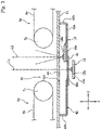
- a floor plate 41 formed of a stainless steel is placed below the gap 6c of the conveyor mechanism 6 in parallel to the X-Y plane.
- the floor plate 41 forms a part of a ceiling of the lower enclosure 4c.
- the X-ray sensor 13 and the illumination part 16 are housed in the lower housing 4 lying below the floor plate 41.
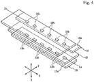
- the X-ray sensor 13 is a line sensor having a plurality of X-ray detection elements 13b mounted on a sensor substrate 13a, as shown in Fig. 4 .
- the plurality of X-ray detection elements 13b are arranged in the X direction perpendicular to the moving direction of the package W1 so as to form an X-ray detection line La.
- the X-ray detection element 13b is a photodiode chip.
- the X-ray sensor 13 has a single X-ray detection line La extending in the X direction but may have a plurality of the lines.
- the illumination part 16 is a line illumination device having a plurality of light-emitting elements 16b mounted on a illumination substrate 16a, as shown in Fig. 4 .
- the plurality of light-emitting elements 16b are arranged in the X direction perpendicular to the moving direction of the package W1 so as to form an illumination line Lb.
- the illumination line Lb is a single line but may be composed of a plurality of lines.
- the light-emitting element 16b is a light-emitting diode (LED) which emits near infrared light or light having a blue wavelength.
- LED light-emitting diode
- a partition 42 formed of a stainless steel is placed beneath the floor plate 41.
- the partition 42 is a single bent member having a support plate 42a and a side plate 42b, and the illumination substrate 16a of the illumination part 16 is fixed on the support plate 42a.
- the side plate 42b is joined to the lower surface of the floor plate 41 without leaving any space.
- the illumination part 16 is located within the region defined by the partition 42, while the X-ray sensor 13 is located outside the partition 42 and below the support plate 42a.
- the support plate 42a of the partition 42 has a detection window 42c above the X-ray sensor 13, and this detection window 42c is closed with a light-shielding member 43.
- the light-shielding member 43 is a plate or sheet and formed of a material that allows passage of the X rays but is capable of blocking the illumination light emitted from the illumination part 16 or reducing the transmittance of the illumination light. In order to endure long-term use, particularly, it is preferably formed of a material that is hardly deteriorated by X rays.
- a sheet containing carbon As the material that is hardly deteriorated by X rays, it is preferable to use a sheet containing carbon.
- a sheet containing carbon it may be a carbon sheet having carbon fibers fixed with a binder resin, a carbon sheet having a woven or nonwoven fabric of carbon fibers reinforced with a binder resin, or a carbon sheet containing a carbon material such as carbon black in a resin. Since the carbon can convert the energy of X rays into heat and dissipate the heat, it can withstand long-term irradiation of X rays.
- PEEK resin polyether ether ketone resin
- the material that is hardly deteriorated by X rays is also possible to use a PEEK resin (polyether ether ketone resin) as the material that is hardly deteriorated by X rays. Since the PEEK resin is a thermoplastic resin that can be easily formed into a sheet or plate and is super heat-resistant, it can withstand long-term irradiation of X rays.
- the floor plate 41 has an opening 41a, and the X-ray detection elements 13b of the X-ray sensor 13 and the light-emitting elements 16b of the illumination part 16 are located beneath the opening 41a.
- the opening 41a is closed with a cover member 44.
- the cover member 44 is formed of a material that allows passage of both the light emitted from the illumination part 16 and the X rays but is hardly deteriorated by long-term irradiation of X rays.
- the cover member 44 is formed of a ULTEM resin (registered trademark) that is an amorphous thermoplastic polyetherimide resin. With the cover member 44, dirt or dust can be prevented from falling on the region where the illumination part 16 is located or the region where the light-shielding member 43 is located.
- ULTEM resin registered trademark
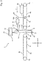
- the centerline of the X-ray detection area in which X rays can be detected by the X-ray sensor 13 is indicated by L1.
- the X-ray detection image-taking line (electromagnetic-wave detection image-taking line) L1 is a line joining the center of the X-ray generator 10 and the center of the X-ray sensor 13.
- the X-ray detection image-taking line represents a detection plane parallel to the X-Z plane rising vertically from the X-ray detection line of the X-ray sensor 13 being a line sensor, and therefore can be restated as X-ray detection image-taking plane.
- the X-ray detection image-taking line L1 of the X-ray sensor 13 passes through the gap 6c of the conveyor mechanism 6 and extends in the Z direction perpendicular to the Y direction being the moving direction of the package W1.
- the centerline of the light detection area in which light can be detected by the optical sensor 15 is indicated by L2 and L3.
- the light detection image-taking line L2 and L3 is a line joining the center of the optical sensor 15 and the center of the illumination part 16.
- the light detection image-taking line L2 and L3 represents a detection plane extending from the light detection line of the optical sensor 15 with a depth in the X direction, and therefore can be restated as light detection image-taking plane.
- a reflection member 17 is provided above the conveyor mechanism 6.
- the reflection surface 17a of the reflection member 17 is inclined 45 degrees with respect to the X-Z plane.
- the light detection image-taking line L3 of the optical sensor 15, which extends parallel to the Y direction, is bent downward by the reflection surface 17a of the reflection member 17 and becomes the light detection image-taking line L2. That is, the illumination light emitted from the illumination part 16 passes the package W1 passing above the gap 6c and is reflected by the reflection surface 17a and received by the optical sensor 15.
- the X-ray sensor 13 and the illumination part 16 are closely arranged beneath the conveyor mechanism 6, and the X-ray detection image-taking line L1 and the light detection image-taking line L2 are arranged parallel to each other without coinciding in the gap 6c of the conveyor mechanism 6.
- optical image data due to detection by the optical sensor 15 can be obtained at the same conditions as image data that can be obtained by applying X rays to the package W1 passing the gap 6c.
- the reflection member 17 is placed so as not to cross the X-ray detection image-taking line L1, the reflection member 17 can be certainly prevented from being deteriorated by the irradiation of the X rays.
- a position sensor 18 is provided in the upstream conveyor mechanism 6a.
- the position sensor 18 is an optical sensor composed of a light-emitting part 18a and a light-receiving part 18b facing each other. With the conveyance path of the package W1 between, the light-emitting part 18a is placed at the upper or lower side thereof, and the light-receiving part 18b faces it at the other side thereof. It should be noted that if the upstream conveyor belt 8a is not a light transmissive one, the light-emitting part 18a and the light-receiving part 18b may face each other in the X direction so as to detect the package W lying on the conveyance surface of the conveyor belt 8a.
- a display unit 19 and a control panel are provided at the front part of the upper enclosure 3a constituting the upper housing 3.
- the display unit 19 may be composed of a display panel such as color liquid crystal panel and its driving circuit.
- Various types of operation buttons are arranged on the control panel.
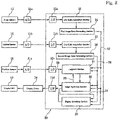
- Fig. 8 shows a circuit block diagram illustrating the outline of an electronic circuit provided in the inspection system 1.
- a controller 20 may be composed of a CPU and a memory; the blocks inside the controller 20 shown in Fig. 8 can be configured by executing software installed in the CPU.
- Detection output from the X-ray sensor 13 can be converted into digital signals at an A/D converter 21a and sent to a line data acquisition section 23 of the controller 20 via an input interface 22a.
- density data detected at the X-ray detection line of the X-ray sensor 13 can be acquired on a line-by-line basis.
- the density data for each line acquired at the line data acquisition section 23 can be sent to and accumulated at a first image data generating section 24, thereby generating a first image data 27 composed of display-sized density data.
- Detection output from the optical sensor 15 can be converted into digital signals at an A/D converter 21b and sent to a line data acquisition section 25 of the controller 20 via an input interface 22b.
- a line data acquisition section 25 density data detected at the light detection line of the optical sensor 15 can be acquired on a line-by-line basis.
- the density data for each line acquired at the line data acquisition section 25 can be sent to and accumulated at a second image data generating section 26, thereby generating a second image data 28 composed of display-sized density data.
- the first image data 27 generated at the first image data generating section 24 as a density image from the X-ray detection output can be sent to a judgment section 31, an image synthesis section 32 and a display switching section 35.
- the second image data 28 generated at the second image data generating section 26 as a density image from the light detection output can also be sent to the judgment section 31, the image synthesis section 32 and the display switching section 35.
- the judgment section 31 and the image synthesis section 32 allow data interchanges between each other.
- Detection output from the position sensor 18 can be converted into digital signals at an A/D converter 21c and sent to the judgment section 31 and the image synthesis section 32 as timing signals 29 via an input interface 22c.
- the first image data 27 and the second image data 28 are combined together.
- Combined image data 33 obtained by combining two types of image data can be sent to the display switching section 35.
- the combined image data 33 can also be sent to the judgment section 31.
- the display switching section 35 can be operable to switch by operating one of the operation buttons on the display panel.
- the combined image data 33 or the first image data 27 or the second image data 28 can be chosen by the display switching section 35 and sent to a display driver 34 via an output interface 22d.
- the display unit 19 can be driven by the display driver 34 so that the screen of the display panel can display an image based on the combined image data 33. Alternatively, the screen can display an image based on the first image data 27 or an image based on the second image data 28.
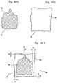
- the package W1 shown in Fig. 9(C) is formed by enclosing a content Wa in a wrapping Wb.
- the package W1 is conveyed in the F direction by the conveyor belt 8a of the upstream conveyor mechanism 6a, passed across the gap 6c and received by the conveyor belt 8b of the downstream conveyor mechanism 6b.
- the wrapping Wb of the package W1 is a bag that is formed of a synthetic resin film that is subjected to printing and therefore cannot be optically seen through, a bag that is formed of a thin metal foil such as aluminum foil and therefore cannot be optically seen through or a bag that is formed of a laminate of a metal foil and a synthetic resin film and therefore cannot be optically seen through.
- it may be a bag enclosing a tray formed of a thin synthetic resin material.
- the content Wa of the package W1 may be snack, processed food for retort pouch, processed meat or fish or fresh food.
- the timing signal 29 obtained from the detection output is sent to the judgment section 31 and the image synthesis section 32 shown in Fig. 8 .
- the package W1 passes the gap 6c of the conveyor mechanism 6, the package W1 is irradiated with the X rays emitted from the X-ray generator 10, so that the X rays transmitted through the package W1 can be detected by the X-ray sensor 13 after passing through the cover member 44 and the light-shielding member 43 shown in Fig. 3 .
- the detection output from the X-ray sensor 13 is sent to the line data acquisition section 23 of the controller 20 shown in Fig. 8 , and the line image data are accumulated at the first image data generating section 24 to generate the first image data 27. Since the wrapping Wb of the package W1 is formed of a thin packaging material, a large amount of X rays can be transmitted. On the other hand, the thickness of the content reduces the amount of X-ray transmission.
- the first image data 27 show the density contrast of the detected amount of X rays; the first data image includes image data showing the outline of the content Wa, as illustrated in Fig. 9(A) , but does not substantially include image data showing the outline of the wrapping Wb.
- the illumination light is applied to the gap 6c from the illumination part 16.
- the illumination light passes through the cover member 44, so that the package W1 passing the gap 6c can be illuminated from below.
- the illumination light passes the package W1, and the transmitted light is reflected by the reflection member 17 and detected by the optical sensor 15.
- the detection output from the optical sensor 15 is sent to the line data acquisition section 25 of the controller 20, and the line image data are accumulated at the second image data generating section 26 to generate the second image data 28.
- the second image data 28 include an image showing the outline of the wrapping Wb, as illustrated in Fig. 9(B) , but do not include an image showing the outline of the content Wa.
- the timing signal 29 teaching the detection timing is sent to the judgment section 31 and the image synthesis section 32.
- the controller 20 has a counter which begins to measure the passage of time from the moment of receiving the timing signal 29 due to detection of the package W1. Alternatively, it may begin to count the number of lines of the line image data obtained from the X-ray sensor 13 and the line image data obtained from the optical sensor 15 from the moment of receiving the timing signal.
- the first image data 27 and the second image data 28 are acquired at the same timing based on the timing signal.
- the image data are acquired such that the image data of the content Wa included in the first image data 27 coincide in relative position with the image data of the wrapping Wb included in the second image data 28.
- the first image data 27 and the second image data 28 can be amended to correct the inclination within the X-Y coordinate plane such that the side of the package W1 in the image extends along the X direction.
- the illumination part 16 and the X-ray sensor 13 are separated from each other by the partition 42 and the light-shielding member 43, so that the illumination light emitted from the illumination part 16 is hardly detected by the X-ray sensor 13. Therefore, the illumination light can be continuously emitted from the illumination part 16 while the X rays transmitted through the package W1 are being detected by the X-ray sensor 13.
- the light passing the package W1 can be continuously detected by the optical sensor 15 with the illumination light emitted continuously during the image detection by the X-ray sensor 13, which increases the amount of data: the first image data 27 acquired by the X-ray sensor 13 and the second image data 28 acquired by the optical sensor 15 as the package W1 passes the gap 6c. It is also possible to increase the conveyance velocity of the package W1 by the conveyor mechanism 6.
- Fig. 9(C) shows a combined image data 33 produced at the image synthesis section 32.
- the combined image data 33 are produced by superposing the first image data 27 and the second image data 28 to occupy the same position based on the timing signal from the position sensor 18.
- the positional relationship between the image of the content Wa and the image of the wrapping Wb is accurately the same as in the moving package W1.
- the combined image data 33 shown in Fig. 9(C) are sent to the display driver 34 and displayed on the display screen of the display unit 19.
- the data about the relative position of the image data of the content Wa and the image data of the wrapping Wb are calculated based on the combined image data 33 produced at the image synthesis section 32.
- calculated are the minimum distance S1 between the front edge of the wrapping Wb and the content Wa, the minimum distance S2 between the rear edge of the wrapping Wb and the content Wa, the minimum distance S3 between the right edge of the wrapping Wb and the content Wa, and the minimum distance S4 between the left edge of the wrapping Wb and the content Wa.
- Whether or not a part of the content Wa is caught in a seal of the wrapping Wb can be determined by obtaining the minimum distances S1, S2, S3 and S4.
- the minimum distance S1 between the front edge of the wrapping Wb and the content Wa is smaller than a predetermined threshold, there is a high possibility that at the front edge of the wrapping Wb, a part of the content Wa is caught in a seal in which the packaging materials are bonded together, causing a seal failure.
- the relative position of the content Wa and the wrapping Wb may also be determined such that the parameters S1, S2, S3 and S4 are calculated by comparing two types of image data 27 and 28 merely on data without superposing and combining the first image data 27 and the second image data 28.
- a first group of coordinate points composed of a plurality of coordinate points indicating the outline of the content Wa included in the first image data 27 are determined on the X-Y coordinates based on the timing signal from the position sensor 18; a second group of coordinate points composed of a plurality of coordinate points indicating the outline of the wrapping Wb included in the second image data 28 are also determined on the X-Y coordinates based on the timing signal. Then, the parameters S1, S2, S3 and S4 are calculated by comparing the first group of coordinate points and the second group of coordinate points.
- the foreign body in the first image data 27 can be fetched and recognized as data different in density from the content Wa. At the judgment section 31, therefore, it is possible to determine the position and size of the foreign body.
- the positional relationship between the content Wa and the wrapping Wb can be determined and the presence of the foreign body can also be detected by using the first image data 27 and the second image data 28.
- the X-ray detection image-taking line L1 passes through the gap 6c between the upstream conveyor mechanism 6a and the downstream conveyor mechanism 6b. Therefore, a scratch on the conveyor belt of the conveyor mechanism 6 or a foreign body attached to the conveyor belt can be prevented from being captured in the first image data 27, so that the image of the scratch or foreign body will never be erroneously identified as a foreign body enclosed in the package W1.
- the light-shield member 43 or the cover member 44 has a scratch or a foreign body attached thereto, they appear as noise data always at the same position in the first image data 27 or the second image data 28, and the noise data can be removed by data correction at the image synthesis section 32 or the judgment section 31, so that they hardly cause detection errors.
- the near infrared light or the like emitted from the illumination part 16 can be applied to the package W1 and the light having passed the package W1 can be detected by the optical sensor 15 to generate the second image data 28.
- the second image data 28 can be generated with the outline of the wrapping Wb of the package W1 detected clearly and accurately.
- the display switching section 35 can be operable to switch by operating one of the operation buttons on the display panel.
- the image only of the first image data 27 or the image only of the second image data 28 can be displayed on the display screen of the display unit 19.
- the image only of the second image data 28 based on the transmitted light from the illumination part 16 can be displayed, whereby when the wrapping Wb is formed of a light transmissive packaging material, whether or not the content is caught in the seal can be determined by obtaining the optical image of the package W1.
- the image to be chosen may be replaced depending on the type of the wrapping Wb.
- the wrapping Wb is a bag that cannot be optically seen through, whether or not the content is caught in the seal or the foreign body is present can be determined by acquiring both the first image data 27 and the second image data 28 and displaying the combined image;
- the wrapping Wb is formed of a light transmissive packaging material, whether or not the content is caught in the seal or the foreign body is present can be determined from the optical image by acquiring only the second image data 28.
- the illumination light can easily be transmitted through the packaging material, even though the wrapping Wb is formed of a patterned packaging material.
- blue light is used as the illumination light, the difference in brightness between the wrapping Wb and the content Wa can be increased in the optical image to have a sharp contrast between the wrapping Wb and the content Wa.
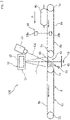
- Fig. 5 shows an inspection system 101 in which the partition 42 is provided below the floor plate 41 and the illumination part 16 is located within the region defined by the partition 42, as in the inspection system 101 shown in Fig. 3 .
- the illumination light is emitted in the Y direction.
- a lower reflection member 45 is provided to face the light-emitting element 16b such that the illumination light can be reflected upward by the lower reflection member 45, thereby providing the light detection image-taking line L3.
- the light detection image-taking line L3 and the X-ray detection image-taking line L1 extend parallel to each other in the Z direction.
- the lower reflection member 45 is placed so as not to cross the X-ray detection image-taking line L1, whereby the lower reflection member 17 is prevented from being irradiated with strong X rays.
- the reflection member 17 is provided above the conveyor mechanism 6 such that the illumination light after passing through the gap 6c upward can be reflected in the Y direction and detected by the optical sensor 15. Also, the detection window 42c of the partition 42 is closed with the light-shielding member 43, while the opening 41a of the floor plate 41 is closed with the cover member 44.
- Fig. 6 shows an inspection system 102 according to an embodiment, in which a common substrate 46 is fixed below the floor plate 41.
- a plurality of the X-ray detection elements 13b constituting the X-ray sensor 13 that is a line sensor are arranged on the common substrate 46, and a plurality of the light-emitting elements 16b constituting the illumination part 16 are also arranged on the common substrate 46.
- a partition 47 for separating the X-ray sensor 13 and the illumination part 16 is mounted with the upper opening of the partition 47 closed with the light-shielding member 43. Also in the inspection system 102, the illumination light emitted from the illumination part 16 can hardly be detected by the X-ray sensor 13.
- Fig. 7 shows an inspection system 103 in which the X-ray sensor 13 and the illumination part 16 are placed below the conveyor mechanism 6. Although not illustrated in Fig. 7 , the X-ray sensor 13 and the illumination part 16 are separated from each other by the partition such that the illumination light from the illumination part 16 does not directly enter the X-ray sensor 13. Moreover, the X-ray sensor 13 is covered with the light-shielding member 43.
- the image-taking line L1 for detection of the X rays from the X-ray generator 10 passes through the gaps 6c and extends in the Z direction, while the light detection image-taking line L4 for imaging taking at the optical sensor 15 passes through the gap 6c but crosses the X-ray detection image-taking line L1.
- the cover member 44 is placed at the gap 6c.
- the surface of the cover member 44 lies almost in the same plane as the upper surface of the conveyor belt 8a of the upstream conveyor mechanism 6a and the upper surface of the conveyor belt 8b of the downstream conveyor mechanism 6b.
- the package W1 conveyed in the Y direction by the upstream conveyor mechanism 6a can be passed to the downstream conveyor mechanism 6b such that it slides on the surface of the cover member 44.
- the X-ray detection image-taking line L1 and the light detection image-taking line L4 cross each other in the vicinity of the surface of the cover member 44.
- the noise superposition on the X-ray sensor due to the illumination light can be suppressed.
- the above-mentioned X-ray or terahertz-wave shielding zone i.e., the inspection zone for the package W is not limited to the one separated from the outside by the X-ray shielding sheet 5; for example, it may be a closed zone enclosed with partitions, wherein the conveyance surface of the conveyor belt is almost trapezoidal with the detection parts such as the X-ray sensor 13 and the optical sensor located at an upper conveyance path of the conveyor belt and with the partitions facing downward ascending and descending parts of the conveyor belt.
Landscapes
- Physics & Mathematics (AREA)
- Life Sciences & Earth Sciences (AREA)
- General Physics & Mathematics (AREA)
- General Life Sciences & Earth Sciences (AREA)
- Geophysics (AREA)
- Health & Medical Sciences (AREA)
- Spectroscopy & Molecular Physics (AREA)
- Chemical & Material Sciences (AREA)
- Analytical Chemistry (AREA)
- Biochemistry (AREA)
- General Health & Medical Sciences (AREA)
- Immunology (AREA)
- Pathology (AREA)
- Toxicology (AREA)
- High Energy & Nuclear Physics (AREA)
- Analysing Materials By The Use Of Radiation (AREA)
- Investigating Or Analysing Materials By Optical Means (AREA)
Claims (8)
- Paketinspektionssystem (1) umfassend: einen Fördermechanismus (6) zum Transportieren eines Pakets (W1), das einen Inhalt in einer Verpackung aufweist; ein Bestrahlungsteil (10) zum Bestrahlen des Pakets mit einer Röntgen- oder einer Terahertzwelle; ein elektromagnetisches Wellenerfassungsteil (13) zum Erfassen der Röntgen- oder Terahertzwelle, die durch das Paket gesendet wurden; ein Beleuchtungsteil (16) zum Beleuchten des Pakets mit einem Licht; und ein optisches Erfassungsteil (15) zum Aufnehmen eines optischen Bildes des Pakets, wobei eine Trennwand (42) zwischen dem elektromagnetischen Wellenerfassungsteil und dem Beleuchtungsteil bereitgestellt ist, dadurch gekennzeichnet, dass: die Trennwand ein lichtabschirmendes Element (43) aufweist, das konfiguriert ist, der Röntgen- oder Terahertzwelle zuzulassen, aber das vom Beleuchtungsteil emittierte Licht wenigstens in einem Pfad zu blockieren oder zu reduzieren, durch den die Röntgenoder Terahertzwelle in das elektromagnetische Wellenerfassungsteil eintritt, um dadurch eine Erfassungsausgabe zu erzeugen, die durch Licht vom Beleuchtungsteil unbeeinflusst ist; und das Bestrahlungsteil und das optische Erfassungsteil an einer Seite eines Transportwegs des Pakets bereitgestellt sind, und das Beleuchtungsteil und das elektromagnetische Wellenerfassungsteil an der anderen Seite davon bereitgestellt sind; wobei ein gemeinsames Substrat (46) unter einer Bodenplatte (41) bereitgestellt ist, die sich unter dem Fördermechanismus befindet, wobei eine Vielzahl von Röntgenerfassungselementen 13b, die das elektromagnetische Wellenerfassungsteil 13, das heißt, einen Liniensensor, konstituieren, auf dem gemeinsamen Substrat 46 angeordnet sind, und eine Vielzahl von Licht emittierenden Elementen 16b, die das Beleuchtungsteil 16 konstituieren, ebenfalls auf dem gemeinsamen Substrat 46 angeordnet sind, und wobei die Trennwand auf dem gemeinsamen Substrat montiert ist und eine Öffnung aufweist, die durch das lichtabschirmende Element geschlossen wird.
- Paketinspektionssystem nach Anspruch 1, wobei das elektromagnetische Wellenerfassungsteil von der Trennwand umschlossen ist, das Beleuchtungsteil außerhalb der Trennwand bereitgestellt ist, und die Trennwand mit dem lichtabschirmenden Element in einer Position versehen ist, die dem elektromagnetischen Wellenerfassungsteil zugewandt ist.
- Paketinspektionssystem nach einem der Ansprüche 1 bis 2, wobei das lichtabschirmende Element Kohlenstoff enthält.
- Paketinspektionssystem nach Anspruch 3, wobei das lichtabschirmende Element eine Kohlenstoffschicht ist, die Kohlenstofffasern und ein Bindeharz enthält.
- Paketinspektionssystem nach einem der Ansprüche 1 bis 2, wobei das lichtabschirmende Element aus einem PEEK- (Polyetheretherketon) Harz gebildet ist.
- Paketinspektionssystem nach Anspruch 1, wobei ein Abdeckelement (44), das konfiguriert ist, den Durchgang der Röntgen- oder Terahertzwelle und dem vom Beleuchtungsteil emittierten Licht zuzulassen, zwischen einem Transportweg des Pakets und dem elektromagnetischen Wellenerfassungsteil und dem Beleuchtungsteil bereitgestellt ist.
- Paketinspektionssystem nach Anspruch 6, wobei das Abdeckelement aus einem thermoplastischen Polyetherimidharz gebildet ist.
- Paketinspektionssystem nach einem der Ansprüche 1 bis 7, wobei der Fördermechanismus eine Lücke (6c) aufweist, durch die das vom Beleuchtungsteil emittierte Licht und die Röntgen- oder Terahertzwelle passieren darf.
Applications Claiming Priority (1)
| Application Number | Priority Date | Filing Date | Title |
|---|---|---|---|
| PCT/JP2013/076984 WO2015049765A1 (ja) | 2013-10-03 | 2013-10-03 | 包装体の検査装置 |
Publications (5)
| Publication Number | Publication Date |
|---|---|
| EP3045897A1 EP3045897A1 (de) | 2016-07-20 |
| EP3045897A4 EP3045897A4 (de) | 2017-05-24 |
| EP3045897B1 EP3045897B1 (de) | 2019-07-03 |
| EP3045897B8 EP3045897B8 (de) | 2019-08-14 |
| EP3045897B2 true EP3045897B2 (de) | 2022-12-28 |
Family
ID=52778375
Family Applications (1)
| Application Number | Title | Priority Date | Filing Date |
|---|---|---|---|
| EP13889357.3A Active EP3045897B2 (de) | 2013-10-03 | 2013-10-03 | Paketinspektionsvorrichtung |
Country Status (5)
| Country | Link |
|---|---|
| US (1) | US9733384B2 (de) |
| EP (1) | EP3045897B2 (de) |
| JP (1) | JP5720028B1 (de) |
| CN (1) | CN104718447B (de) |
| WO (1) | WO2015049765A1 (de) |
Families Citing this family (21)
| Publication number | Priority date | Publication date | Assignee | Title |
|---|---|---|---|---|
| JP6335499B2 (ja) * | 2013-12-13 | 2018-05-30 | 株式会社イシダ | 光学検査装置 |
| JP6535755B2 (ja) * | 2015-04-15 | 2019-06-26 | エクスロン インターナショナル ゲゼルシャフト ミット ベシュレンクテル ハフツングYxlon International Gmbh | 電子部品を試験する方法 |
| WO2017003665A1 (en) | 2015-06-30 | 2017-01-05 | Illinois Tool Works Inc. | Inline x-ray measurement apparatus and method |
| CA2952775C (en) * | 2015-12-23 | 2020-04-14 | Raysecur Inc. | Mail screening apparatus |
| JP2018004365A (ja) * | 2016-06-30 | 2018-01-11 | ローム株式会社 | 反射式検出装置 |
| CN106185226B (zh) * | 2016-09-29 | 2019-05-03 | 同方威视技术股份有限公司 | 用于集装物检查系统的检测通道的组合输送装置、及集装物检查系统 |
| WO2018131149A1 (ja) * | 2017-01-13 | 2018-07-19 | 株式会社ニコン | 粉末収容容器および異物の検査方法 |
| CN107193051A (zh) * | 2017-07-07 | 2017-09-22 | 深圳翠博微系统有限公司 | 一种太赫兹传送带检测系统 |
| CN109188554B (zh) * | 2018-08-13 | 2021-05-25 | 北京逸智联科技有限公司 | 一种化妆品包装质量检测系统以及检测方法 |
| KR20200082002A (ko) * | 2018-12-28 | 2020-07-08 | (주)미래컴퍼니 | 테라헤르츠파를 이용한 검사장치 |
| KR102153450B1 (ko) * | 2018-12-28 | 2020-09-08 | (주)미래컴퍼니 | 테라헤르츠파를 이용한 검사장치 |
| JP6783347B1 (ja) * | 2019-05-27 | 2020-11-11 | Ckd株式会社 | 検査装置、包装シート製造装置及び包装シート製造方法 |
| JP6752941B1 (ja) * | 2019-06-17 | 2020-09-09 | Ckd株式会社 | 検査装置、包装体製造装置及び包装体製造方法 |
| CN110632676B (zh) * | 2019-09-05 | 2021-01-12 | 福建恒安集团有限公司 | 卫生用品生产线上的高分子材料缺失检测机构及检测方法 |
| JP7382228B2 (ja) * | 2019-12-26 | 2023-11-16 | ニッタ株式会社 | 搬送用ベルト |
| US12276623B2 (en) | 2020-08-26 | 2025-04-15 | Hamamatsu Photonics K.K. | Foreign matter inspection device |
| US11284018B1 (en) * | 2020-09-15 | 2022-03-22 | Applied Materials, Inc. | Smart camera substrate |
| US11573175B2 (en) | 2020-12-22 | 2023-02-07 | Industrial Technology Research Institute | Calibration assembly for scan device and calibration system |
| US12101581B2 (en) * | 2022-04-04 | 2024-09-24 | Tyco Fire & Security Gmbh | Method and system for recording a mail screening process |
| JP2024133851A (ja) * | 2023-03-20 | 2024-10-03 | 株式会社イシダ | X線検査装置 |
| CN116461801B (zh) * | 2023-04-24 | 2025-06-20 | 河北龙之养饮料有限公司 | 包装箱填充物检测装置及方法 |
Family Cites Families (29)
| Publication number | Priority date | Publication date | Assignee | Title |
|---|---|---|---|---|
| JPS5953500B2 (ja) | 1978-06-06 | 1984-12-25 | 株式会社東芝 | X線透視検査装置 |
| JPS5817544A (ja) | 1981-07-23 | 1983-02-01 | Matsushita Electric Ind Co Ltd | 磁気記録媒体の製造方法 |
| JPS5817544U (ja) * | 1981-07-27 | 1983-02-03 | ソフテツクス株式会社 | 軟x線像と実体像とを観察するテレビジヨン装置 |
| JPH0252246A (ja) * | 1988-08-15 | 1990-02-21 | Tokyo Electron Ltd | X線検査装置 |
| JPH06281598A (ja) | 1991-07-26 | 1994-10-07 | Motoronikusu:Kk | 多層ワークのx線画像と光学系画像の同時映し出し装 置及びその方法 |
| JPH09127017A (ja) * | 1995-10-31 | 1997-05-16 | Shimazu Mekutemu Kk | 計量機能付きx線異物検出装置及びその装置を用いた商品検査方法 |
| US5901198A (en) * | 1997-10-10 | 1999-05-04 | Analogic Corporation | Computed tomography scanning target detection using target surface normals |
| JP2000135268A (ja) | 1998-08-26 | 2000-05-16 | Yuyama Seisakusho:Kk | 錠剤検査装置 |
| US6324253B1 (en) | 1998-08-26 | 2001-11-27 | Yuyama Mfg. Co., Ltd. | Tablet inspection apparatus |
| EP1016881B1 (de) | 1998-12-28 | 2005-12-21 | Kabushiki Kaisha Toshiba | Strahlungsdetektoreinrichtung |
| JP2002168803A (ja) * | 2000-11-30 | 2002-06-14 | Anritsu Corp | X線異物検出装置 |
| US6510195B1 (en) | 2001-07-18 | 2003-01-21 | Koninklijke Philips Electronics, N.V. | Solid state x-radiation detector modules and mosaics thereof, and an imaging method and apparatus employing the same |
| JP2006084275A (ja) | 2004-09-15 | 2006-03-30 | Hitachi Ltd | 爆発物等の探知方法および装置 |
| JP4536533B2 (ja) | 2005-01-26 | 2010-09-01 | アンリツ産機システム株式会社 | X線異物検出装置 |
| US20060185087A1 (en) * | 2005-02-08 | 2006-08-24 | Coppens Daniel D | Rigid patient support element for low patient skin damage when used in a radiation therapy environment |
| JP4730526B2 (ja) | 2005-06-27 | 2011-07-20 | 独立行政法人理化学研究所 | 封入物検査装置 |
| DE102006033497B4 (de) | 2006-07-19 | 2014-05-22 | Siemens Aktiengesellschaft | Strahlungsdetektor für Röntgen- oder Gammastrahlen und Verfahren zu seiner Herstellung |
| JP5358073B2 (ja) * | 2007-08-10 | 2013-12-04 | ライオンエンジニアリング株式会社 | 分包シート検査システム及び検査方法 |
| US8489232B2 (en) | 2008-09-30 | 2013-07-16 | Amazon Technologies, Inc. | Systems and methods for receiving shipment parcels |
| JP5118661B2 (ja) | 2009-03-25 | 2013-01-16 | 浜松ホトニクス株式会社 | X線撮像装置 |
| JP5302238B2 (ja) | 2009-05-13 | 2013-10-02 | 株式会社イシダ | X線検査装置 |
| SG168488A1 (en) | 2009-07-16 | 2011-02-28 | Asml Netherlands Bv | Position calibration of alignment heads in a multi-head alignment system |
| JP5408432B2 (ja) * | 2009-12-18 | 2014-02-05 | 横河電機株式会社 | 放射線検出装置及びこの装置を用いた放射線検出方法 |
| JP4810665B1 (ja) | 2010-05-10 | 2011-11-09 | 株式会社 システムスクエア | 光学検査装置及び光学検査方法 |
| JP2012168128A (ja) | 2011-02-16 | 2012-09-06 | Canon Inc | 放射線検出装置及び放射線撮像システム |
| JP5453350B2 (ja) | 2011-06-23 | 2014-03-26 | 株式会社 システムスクエア | 包装体の検査装置 |
| DE202011051843U1 (de) | 2011-11-02 | 2011-11-15 | Wipotec Wiege- Und Positioniersysteme Gmbh | Prüfgerät |
| JP3175930U (ja) * | 2012-03-16 | 2012-06-07 | 株式会社イシダ | X線検査装置 |
| JP5720029B2 (ja) | 2012-10-17 | 2015-05-20 | 株式会社 システムスクエア | 包装体の検査装置 |
-
2013
- 2013-10-03 JP JP2014540243A patent/JP5720028B1/ja active Active
- 2013-10-03 US US14/418,895 patent/US9733384B2/en active Active
- 2013-10-03 CN CN201380043026.8A patent/CN104718447B/zh active Active
- 2013-10-03 EP EP13889357.3A patent/EP3045897B2/de active Active
- 2013-10-03 WO PCT/JP2013/076984 patent/WO2015049765A1/ja not_active Ceased
Also Published As
| Publication number | Publication date |
|---|---|
| US20160033404A1 (en) | 2016-02-04 |
| JP5720028B1 (ja) | 2015-05-20 |
| CN104718447A (zh) | 2015-06-17 |
| WO2015049765A1 (ja) | 2015-04-09 |
| CN104718447B (zh) | 2017-07-28 |
| EP3045897B8 (de) | 2019-08-14 |
| EP3045897A1 (de) | 2016-07-20 |
| EP3045897B1 (de) | 2019-07-03 |
| US9733384B2 (en) | 2017-08-15 |
| JPWO2015049765A1 (ja) | 2017-03-09 |
| EP3045897A4 (de) | 2017-05-24 |
Similar Documents
| Publication | Publication Date | Title |
|---|---|---|
| EP3045897B2 (de) | Paketinspektionsvorrichtung | |
| EP2887056B1 (de) | Vorrichtung zur inspektion von verpackungskörpern | |
| JP5884144B1 (ja) | 包装体の検査装置 | |
| US12276623B2 (en) | Foreign matter inspection device | |
| JP5124226B2 (ja) | 放射線検出器 | |
| KR102866743B1 (ko) | 케이스 물품 검사 시스템 및 방법 | |
| JP5344792B2 (ja) | 対象物の欠陥を検出する測定システム及び方法 | |
| EP2264898B1 (de) | Optischer Näherungssensor | |
| JP5791101B2 (ja) | 貼り合せ板状体検査装置及び方法 | |
| JP5884145B1 (ja) | 電磁波検知部と光学検知部を使用した検査装置 | |
| JP6617238B2 (ja) | 包装体の検査装置 | |
| JP4213106B2 (ja) | 外観検査装置及びptp包装機 | |
| JP2020190441A (ja) | 皺検査装置、皺判定装置及び皺検査方法 | |
| JP2005164488A (ja) | 検査器及び検査装置 | |
| JP6204892B2 (ja) | 乗客コンベア用移動手摺劣化診断装置 | |
| JP6914753B2 (ja) | パッケージ品の内容物検査方法および検査装置 | |
| JP2019039683A (ja) | 光検査装置、及び異常検出方法 | |
| JP2018141673A (ja) | 放射線検出器および放射線検出装置 | |
| JP5513582B2 (ja) | 放射線検出器 | |
| WO2024106458A1 (ja) | 撮像装置、当該撮像装置を用いた検査装置、及び撮像方法 | |
| JP2019039684A (ja) | 光検査装置、及び出力強度調整方法 | |
| JP2006071524A (ja) | プレス成型品の亀裂検出装置 |
Legal Events
| Date | Code | Title | Description |
|---|---|---|---|
| PUAI | Public reference made under article 153(3) epc to a published international application that has entered the european phase |
Free format text: ORIGINAL CODE: 0009012 |
|
| 17P | Request for examination filed |
Effective date: 20150121 |
|
| AK | Designated contracting states |
Kind code of ref document: A1 Designated state(s): AL AT BE BG CH CY CZ DE DK EE ES FI FR GB GR HR HU IE IS IT LI LT LU LV MC MK MT NL NO PL PT RO RS SE SI SK SM TR |
|
| AX | Request for extension of the european patent |
Extension state: BA ME |
|
| DAX | Request for extension of the european patent (deleted) | ||
| A4 | Supplementary search report drawn up and despatched |
Effective date: 20170426 |
|
| RIC1 | Information provided on ipc code assigned before grant |
Ipc: G01N 21/90 20060101ALI20170420BHEP Ipc: G01N 23/04 20060101AFI20170420BHEP Ipc: G01N 21/3581 20140101ALI20170420BHEP |
|
| GRAP | Despatch of communication of intention to grant a patent |
Free format text: ORIGINAL CODE: EPIDOSNIGR1 |
|
| STAA | Information on the status of an ep patent application or granted ep patent |
Free format text: STATUS: GRANT OF PATENT IS INTENDED |
|
| INTG | Intention to grant announced |
Effective date: 20190207 |
|
| GRAS | Grant fee paid |
Free format text: ORIGINAL CODE: EPIDOSNIGR3 |
|
| GRAA | (expected) grant |
Free format text: ORIGINAL CODE: 0009210 |
|
| STAA | Information on the status of an ep patent application or granted ep patent |
Free format text: STATUS: THE PATENT HAS BEEN GRANTED |
|
| AK | Designated contracting states |
Kind code of ref document: B1 Designated state(s): AL AT BE BG CH CY CZ DE DK EE ES FI FR GB GR HR HU IE IS IT LI LT LU LV MC MK MT NL NO PL PT RO RS SE SI SK SM TR |
|
| REG | Reference to a national code |
Ref country code: GB Ref legal event code: FG4D |
|
| REG | Reference to a national code |
Ref country code: CH Ref legal event code: EP Ref country code: AT Ref legal event code: REF Ref document number: 1151606 Country of ref document: AT Kind code of ref document: T Effective date: 20190715 |
|
| RAP2 | Party data changed (patent owner data changed or rights of a patent transferred) |
Owner name: SYSTEM SQUARE INC. |
|
| REG | Reference to a national code |
Ref country code: IE Ref legal event code: FG4D |
|
| REG | Reference to a national code |
Ref country code: DE Ref legal event code: R096 Ref document number: 602013057525 Country of ref document: DE |
|
| REG | Reference to a national code |
Ref country code: CH Ref legal event code: PK Free format text: BERICHTIGUNG B8 |
|
| REG | Reference to a national code |
Ref country code: NL Ref legal event code: MP Effective date: 20190703 |
|
| REG | Reference to a national code |
Ref country code: LT Ref legal event code: MG4D |
|
| REG | Reference to a national code |
Ref country code: AT Ref legal event code: MK05 Ref document number: 1151606 Country of ref document: AT Kind code of ref document: T Effective date: 20190703 |
|
| PG25 | Lapsed in a contracting state [announced via postgrant information from national office to epo] |
Ref country code: LT Free format text: LAPSE BECAUSE OF FAILURE TO SUBMIT A TRANSLATION OF THE DESCRIPTION OR TO PAY THE FEE WITHIN THE PRESCRIBED TIME-LIMIT Effective date: 20190703 Ref country code: CZ Free format text: LAPSE BECAUSE OF FAILURE TO SUBMIT A TRANSLATION OF THE DESCRIPTION OR TO PAY THE FEE WITHIN THE PRESCRIBED TIME-LIMIT Effective date: 20190703 Ref country code: NL Free format text: LAPSE BECAUSE OF FAILURE TO SUBMIT A TRANSLATION OF THE DESCRIPTION OR TO PAY THE FEE WITHIN THE PRESCRIBED TIME-LIMIT Effective date: 20190703 Ref country code: PT Free format text: LAPSE BECAUSE OF FAILURE TO SUBMIT A TRANSLATION OF THE DESCRIPTION OR TO PAY THE FEE WITHIN THE PRESCRIBED TIME-LIMIT Effective date: 20191104 Ref country code: BG Free format text: LAPSE BECAUSE OF FAILURE TO SUBMIT A TRANSLATION OF THE DESCRIPTION OR TO PAY THE FEE WITHIN THE PRESCRIBED TIME-LIMIT Effective date: 20191003 Ref country code: SE Free format text: LAPSE BECAUSE OF FAILURE TO SUBMIT A TRANSLATION OF THE DESCRIPTION OR TO PAY THE FEE WITHIN THE PRESCRIBED TIME-LIMIT Effective date: 20190703 Ref country code: HR Free format text: LAPSE BECAUSE OF FAILURE TO SUBMIT A TRANSLATION OF THE DESCRIPTION OR TO PAY THE FEE WITHIN THE PRESCRIBED TIME-LIMIT Effective date: 20190703 Ref country code: AT Free format text: LAPSE BECAUSE OF FAILURE TO SUBMIT A TRANSLATION OF THE DESCRIPTION OR TO PAY THE FEE WITHIN THE PRESCRIBED TIME-LIMIT Effective date: 20190703 Ref country code: NO Free format text: LAPSE BECAUSE OF FAILURE TO SUBMIT A TRANSLATION OF THE DESCRIPTION OR TO PAY THE FEE WITHIN THE PRESCRIBED TIME-LIMIT Effective date: 20191003 Ref country code: FI Free format text: LAPSE BECAUSE OF FAILURE TO SUBMIT A TRANSLATION OF THE DESCRIPTION OR TO PAY THE FEE WITHIN THE PRESCRIBED TIME-LIMIT Effective date: 20190703 |
|
| PG25 | Lapsed in a contracting state [announced via postgrant information from national office to epo] |
Ref country code: IS Free format text: LAPSE BECAUSE OF FAILURE TO SUBMIT A TRANSLATION OF THE DESCRIPTION OR TO PAY THE FEE WITHIN THE PRESCRIBED TIME-LIMIT Effective date: 20191103 Ref country code: GR Free format text: LAPSE BECAUSE OF FAILURE TO SUBMIT A TRANSLATION OF THE DESCRIPTION OR TO PAY THE FEE WITHIN THE PRESCRIBED TIME-LIMIT Effective date: 20191004 Ref country code: LV Free format text: LAPSE BECAUSE OF FAILURE TO SUBMIT A TRANSLATION OF THE DESCRIPTION OR TO PAY THE FEE WITHIN THE PRESCRIBED TIME-LIMIT Effective date: 20190703 Ref country code: AL Free format text: LAPSE BECAUSE OF FAILURE TO SUBMIT A TRANSLATION OF THE DESCRIPTION OR TO PAY THE FEE WITHIN THE PRESCRIBED TIME-LIMIT Effective date: 20190703 Ref country code: RS Free format text: LAPSE BECAUSE OF FAILURE TO SUBMIT A TRANSLATION OF THE DESCRIPTION OR TO PAY THE FEE WITHIN THE PRESCRIBED TIME-LIMIT Effective date: 20190703 Ref country code: ES Free format text: LAPSE BECAUSE OF FAILURE TO SUBMIT A TRANSLATION OF THE DESCRIPTION OR TO PAY THE FEE WITHIN THE PRESCRIBED TIME-LIMIT Effective date: 20190703 |
|
| PG25 | Lapsed in a contracting state [announced via postgrant information from national office to epo] |
Ref country code: TR Free format text: LAPSE BECAUSE OF FAILURE TO SUBMIT A TRANSLATION OF THE DESCRIPTION OR TO PAY THE FEE WITHIN THE PRESCRIBED TIME-LIMIT Effective date: 20190703 |
|
| REG | Reference to a national code |
Ref country code: DE Ref legal event code: R026 Ref document number: 602013057525 Country of ref document: DE |
|
| PLBI | Opposition filed |
Free format text: ORIGINAL CODE: 0009260 |
|
| PG25 | Lapsed in a contracting state [announced via postgrant information from national office to epo] |
Ref country code: RO Free format text: LAPSE BECAUSE OF FAILURE TO SUBMIT A TRANSLATION OF THE DESCRIPTION OR TO PAY THE FEE WITHIN THE PRESCRIBED TIME-LIMIT Effective date: 20190703 Ref country code: DK Free format text: LAPSE BECAUSE OF FAILURE TO SUBMIT A TRANSLATION OF THE DESCRIPTION OR TO PAY THE FEE WITHIN THE PRESCRIBED TIME-LIMIT Effective date: 20190703 Ref country code: EE Free format text: LAPSE BECAUSE OF FAILURE TO SUBMIT A TRANSLATION OF THE DESCRIPTION OR TO PAY THE FEE WITHIN THE PRESCRIBED TIME-LIMIT Effective date: 20190703 Ref country code: PL Free format text: LAPSE BECAUSE OF FAILURE TO SUBMIT A TRANSLATION OF THE DESCRIPTION OR TO PAY THE FEE WITHIN THE PRESCRIBED TIME-LIMIT Effective date: 20190703 |
|
| 26 | Opposition filed |
Opponent name: WIPOTEC GMBH Effective date: 20200403 |
|
| PG25 | Lapsed in a contracting state [announced via postgrant information from national office to epo] |
Ref country code: SK Free format text: LAPSE BECAUSE OF FAILURE TO SUBMIT A TRANSLATION OF THE DESCRIPTION OR TO PAY THE FEE WITHIN THE PRESCRIBED TIME-LIMIT Effective date: 20190703 Ref country code: MC Free format text: LAPSE BECAUSE OF FAILURE TO SUBMIT A TRANSLATION OF THE DESCRIPTION OR TO PAY THE FEE WITHIN THE PRESCRIBED TIME-LIMIT Effective date: 20190703 Ref country code: SM Free format text: LAPSE BECAUSE OF FAILURE TO SUBMIT A TRANSLATION OF THE DESCRIPTION OR TO PAY THE FEE WITHIN THE PRESCRIBED TIME-LIMIT Effective date: 20190703 Ref country code: IS Free format text: LAPSE BECAUSE OF FAILURE TO SUBMIT A TRANSLATION OF THE DESCRIPTION OR TO PAY THE FEE WITHIN THE PRESCRIBED TIME-LIMIT Effective date: 20200224 |
|
| REG | Reference to a national code |
Ref country code: CH Ref legal event code: PL |
|
| PLAX | Notice of opposition and request to file observation + time limit sent |
Free format text: ORIGINAL CODE: EPIDOSNOBS2 |
|
| PG2D | Information on lapse in contracting state deleted |
Ref country code: IS |
|
| PG25 | Lapsed in a contracting state [announced via postgrant information from national office to epo] |
Ref country code: CH Free format text: LAPSE BECAUSE OF NON-PAYMENT OF DUE FEES Effective date: 20191031 Ref country code: LU Free format text: LAPSE BECAUSE OF NON-PAYMENT OF DUE FEES Effective date: 20191003 Ref country code: LI Free format text: LAPSE BECAUSE OF NON-PAYMENT OF DUE FEES Effective date: 20191031 |
|
| REG | Reference to a national code |
Ref country code: BE Ref legal event code: MM Effective date: 20191031 |
|
| PG25 | Lapsed in a contracting state [announced via postgrant information from national office to epo] |
Ref country code: SI Free format text: LAPSE BECAUSE OF FAILURE TO SUBMIT A TRANSLATION OF THE DESCRIPTION OR TO PAY THE FEE WITHIN THE PRESCRIBED TIME-LIMIT Effective date: 20190703 Ref country code: BE Free format text: LAPSE BECAUSE OF NON-PAYMENT OF DUE FEES Effective date: 20191031 |
|
| PLBB | Reply of patent proprietor to notice(s) of opposition received |
Free format text: ORIGINAL CODE: EPIDOSNOBS3 |
|
| PG25 | Lapsed in a contracting state [announced via postgrant information from national office to epo] |
Ref country code: IE Free format text: LAPSE BECAUSE OF NON-PAYMENT OF DUE FEES Effective date: 20191003 |
|
| PG25 | Lapsed in a contracting state [announced via postgrant information from national office to epo] |
Ref country code: CY Free format text: LAPSE BECAUSE OF FAILURE TO SUBMIT A TRANSLATION OF THE DESCRIPTION OR TO PAY THE FEE WITHIN THE PRESCRIBED TIME-LIMIT Effective date: 20190703 |
|
| PG25 | Lapsed in a contracting state [announced via postgrant information from national office to epo] |
Ref country code: HU Free format text: LAPSE BECAUSE OF FAILURE TO SUBMIT A TRANSLATION OF THE DESCRIPTION OR TO PAY THE FEE WITHIN THE PRESCRIBED TIME-LIMIT; INVALID AB INITIO Effective date: 20131003 Ref country code: MT Free format text: LAPSE BECAUSE OF FAILURE TO SUBMIT A TRANSLATION OF THE DESCRIPTION OR TO PAY THE FEE WITHIN THE PRESCRIBED TIME-LIMIT Effective date: 20190703 |
|
| REG | Reference to a national code |
Ref country code: CH Ref legal event code: PK Free format text: BERICHTIGUNGEN |
|
| RIC2 | Information provided on ipc code assigned after grant |
Ipc: G01V 8/10 20060101ALI20220304BHEP Ipc: G01V 11/00 20060101ALI20220304BHEP Ipc: G01V 5/00 20060101ALI20220304BHEP Ipc: G01N 21/90 20060101ALI20220304BHEP Ipc: G01N 21/3581 20140101ALI20220304BHEP Ipc: G01N 23/04 20180101AFI20220304BHEP |
|
| PG25 | Lapsed in a contracting state [announced via postgrant information from national office to epo] |
Ref country code: MK Free format text: LAPSE BECAUSE OF FAILURE TO SUBMIT A TRANSLATION OF THE DESCRIPTION OR TO PAY THE FEE WITHIN THE PRESCRIBED TIME-LIMIT Effective date: 20190703 |
|
| PUAH | Patent maintained in amended form |
Free format text: ORIGINAL CODE: 0009272 |
|
| STAA | Information on the status of an ep patent application or granted ep patent |
Free format text: STATUS: PATENT MAINTAINED AS AMENDED |
|
| 27A | Patent maintained in amended form |
Effective date: 20221228 |
|
| AK | Designated contracting states |
Kind code of ref document: B2 Designated state(s): AL AT BE BG CH CY CZ DE DK EE ES FI FR GB GR HR HU IE IS IT LI LT LU LV MC MK MT NL NO PL PT RO RS SE SI SK SM TR |
|
| REG | Reference to a national code |
Ref country code: DE Ref legal event code: R102 Ref document number: 602013057525 Country of ref document: DE |
|
| PGFP | Annual fee paid to national office [announced via postgrant information from national office to epo] |
Ref country code: GB Payment date: 20231004 Year of fee payment: 11 |
|
| PGFP | Annual fee paid to national office [announced via postgrant information from national office to epo] |
Ref country code: FR Payment date: 20231026 Year of fee payment: 11 |
|
| GBPC | Gb: european patent ceased through non-payment of renewal fee |
Effective date: 20241003 |
|
| PG25 | Lapsed in a contracting state [announced via postgrant information from national office to epo] |
Ref country code: GB Free format text: LAPSE BECAUSE OF NON-PAYMENT OF DUE FEES Effective date: 20241003 |
|
| PG25 | Lapsed in a contracting state [announced via postgrant information from national office to epo] |
Ref country code: FR Free format text: LAPSE BECAUSE OF NON-PAYMENT OF DUE FEES Effective date: 20241031 |
|
| PGFP | Annual fee paid to national office [announced via postgrant information from national office to epo] |
Ref country code: DE Payment date: 20251023 Year of fee payment: 13 |
|
| PGFP | Annual fee paid to national office [announced via postgrant information from national office to epo] |
Ref country code: IT Payment date: 20251006 Year of fee payment: 13 |