EP3045702A1 - Kraftstoffeinspritzsteuerungsvorrichtung für einen motor und kraftstoffeinspritzsteuerungsverfahren für einen motor - Google Patents
Kraftstoffeinspritzsteuerungsvorrichtung für einen motor und kraftstoffeinspritzsteuerungsverfahren für einen motor Download PDFInfo
- Publication number
- EP3045702A1 EP3045702A1 EP13892899.9A EP13892899A EP3045702A1 EP 3045702 A1 EP3045702 A1 EP 3045702A1 EP 13892899 A EP13892899 A EP 13892899A EP 3045702 A1 EP3045702 A1 EP 3045702A1
- Authority
- EP
- European Patent Office
- Prior art keywords
- pulse width
- fuel
- pressure
- intake
- flow rate
- Prior art date
- Legal status (The legal status is an assumption and is not a legal conclusion. Google has not performed a legal analysis and makes no representation as to the accuracy of the status listed.)
- Granted
Links
Images


Classifications
-
- F—MECHANICAL ENGINEERING; LIGHTING; HEATING; WEAPONS; BLASTING
- F02—COMBUSTION ENGINES; HOT-GAS OR COMBUSTION-PRODUCT ENGINE PLANTS
- F02D—CONTROLLING COMBUSTION ENGINES
- F02D41/00—Electrical control of supply of combustible mixture or its constituents
- F02D41/30—Controlling fuel injection
- F02D41/38—Controlling fuel injection of the high pressure type
- F02D41/40—Controlling fuel injection of the high pressure type with means for controlling injection timing or duration
- F02D41/402—Multiple injections
- F02D41/405—Multiple injections with post injections
-
- F—MECHANICAL ENGINEERING; LIGHTING; HEATING; WEAPONS; BLASTING
- F02—COMBUSTION ENGINES; HOT-GAS OR COMBUSTION-PRODUCT ENGINE PLANTS
- F02D—CONTROLLING COMBUSTION ENGINES
- F02D41/00—Electrical control of supply of combustible mixture or its constituents
- F02D41/02—Circuit arrangements for generating control signals
- F02D41/18—Circuit arrangements for generating control signals by measuring intake air flow
- F02D41/182—Circuit arrangements for generating control signals by measuring intake air flow for the control of a fuel injection device
-
- F—MECHANICAL ENGINEERING; LIGHTING; HEATING; WEAPONS; BLASTING
- F02—COMBUSTION ENGINES; HOT-GAS OR COMBUSTION-PRODUCT ENGINE PLANTS
- F02D—CONTROLLING COMBUSTION ENGINES
- F02D41/00—Electrical control of supply of combustible mixture or its constituents
- F02D41/30—Controlling fuel injection
- F02D41/32—Controlling fuel injection of the low pressure type
- F02D41/34—Controlling fuel injection of the low pressure type with means for controlling injection timing or duration
-
- F—MECHANICAL ENGINEERING; LIGHTING; HEATING; WEAPONS; BLASTING
- F02—COMBUSTION ENGINES; HOT-GAS OR COMBUSTION-PRODUCT ENGINE PLANTS
- F02D—CONTROLLING COMBUSTION ENGINES
- F02D41/00—Electrical control of supply of combustible mixture or its constituents
- F02D41/0002—Controlling intake air
- F02D2041/001—Controlling intake air for engines with variable valve actuation
-
- F—MECHANICAL ENGINEERING; LIGHTING; HEATING; WEAPONS; BLASTING
- F02—COMBUSTION ENGINES; HOT-GAS OR COMBUSTION-PRODUCT ENGINE PLANTS
- F02D—CONTROLLING COMBUSTION ENGINES
- F02D2200/00—Input parameters for engine control
- F02D2200/02—Input parameters for engine control the parameters being related to the engine
- F02D2200/04—Engine intake system parameters
- F02D2200/0406—Intake manifold pressure
-
- F—MECHANICAL ENGINEERING; LIGHTING; HEATING; WEAPONS; BLASTING
- F02—COMBUSTION ENGINES; HOT-GAS OR COMBUSTION-PRODUCT ENGINE PLANTS
- F02D—CONTROLLING COMBUSTION ENGINES
- F02D2200/00—Input parameters for engine control
- F02D2200/02—Input parameters for engine control the parameters being related to the engine
- F02D2200/06—Fuel or fuel supply system parameters
- F02D2200/0602—Fuel pressure
-
- F—MECHANICAL ENGINEERING; LIGHTING; HEATING; WEAPONS; BLASTING
- F02—COMBUSTION ENGINES; HOT-GAS OR COMBUSTION-PRODUCT ENGINE PLANTS
- F02D—CONTROLLING COMBUSTION ENGINES
- F02D2200/00—Input parameters for engine control
- F02D2200/70—Input parameters for engine control said parameters being related to the vehicle exterior
- F02D2200/703—Atmospheric pressure
-
- F—MECHANICAL ENGINEERING; LIGHTING; HEATING; WEAPONS; BLASTING
- F02—COMBUSTION ENGINES; HOT-GAS OR COMBUSTION-PRODUCT ENGINE PLANTS
- F02D—CONTROLLING COMBUSTION ENGINES
- F02D2250/00—Engine control related to specific problems or objectives
- F02D2250/31—Control of the fuel pressure
-
- Y—GENERAL TAGGING OF NEW TECHNOLOGICAL DEVELOPMENTS; GENERAL TAGGING OF CROSS-SECTIONAL TECHNOLOGIES SPANNING OVER SEVERAL SECTIONS OF THE IPC; TECHNICAL SUBJECTS COVERED BY FORMER USPC CROSS-REFERENCE ART COLLECTIONS [XRACs] AND DIGESTS
- Y02—TECHNOLOGIES OR APPLICATIONS FOR MITIGATION OR ADAPTATION AGAINST CLIMATE CHANGE
- Y02T—CLIMATE CHANGE MITIGATION TECHNOLOGIES RELATED TO TRANSPORTATION
- Y02T10/00—Road transport of goods or passengers
- Y02T10/10—Internal combustion engine [ICE] based vehicles
- Y02T10/40—Engine management systems
Definitions
- the present invention relates to a fuel injection control device of an engine and a fuel injection control method of the engine.
- JP1996-100695A discloses a fuel injection control device of an engine for controlling operation of a fuel injection valve that makes fuel injection into an intake passage.
- this fuel injection control device calculates an effective injection time and an ineffective injection time based on a differential pressure between a fuel pressure and the intake pressure, and sets an injection time of the fuel injection valve from the effective injection time and the ineffective injection time.
- the fuel injection valve that is mounted on the engine is controlled to open according to a target pulse width that defines a valve-opening time, and basically, the target pulse width is linearly proportional to an injection flow rate of a fuel injected from the fuel injection valve. In other words, as the target pulse width increases, the flow rate of the fuel injected from the fuel injection valve increases.
- JP1995-100695A consideration is given to setting of the target pulse width according to the differential pressure between the fuel pressure and the intake pressure, but no consideration is given to an influence of using a variable fuel pressure system in particular, by which the fuel pressure is varied actively.
- optimum fuel injection with regard to an engine operation state cannot be made, and deterioration in fuel consumption performance and exhaust performance may be caused especially in a region where the fuel injection flow rate of the fuel injection valve is low.
- a fuel injection control device of an engine includes a fuel injection valve configured to inject a fuel according to a target pulse width into an intake passage, an intake flow rate detection unit arranged to detect a flow rate of an intake air supplied to the engine, an intake pressure detection unit arranged to detect an intake pressure in the intake passage, a fuel pressure detection unit arranged to detect a pressure of a fuel supplied to the fuel injection valve, and a pressure control unit configured to control the fuel pressure according to an engine operation state.
- the fuel injection control device includes a request pulse width calculation unit configured to calculate a request pulse width on the basis of an intake flow rate detected by the intake flow rate detection unit, a fuel pressure detected by the fuel pressure detection unit, and a differential pressure between the fuel pressure and an intake pressure detected by the intake pressure detection unit, a post-correction request pulse width calculation unit configured to calculate a post-correction request pulse width through correcting the request pulse width according to the differential pressure, when injecting a fuel of which flow rate is lower than a predetermined flow rate; and a target pulse width setting unit configured to set the target pulse width on the basis of the post-correction request pulse width.
- a request pulse width calculation unit configured to calculate a request pulse width on the basis of an intake flow rate detected by the intake flow rate detection unit, a fuel pressure detected by the fuel pressure detection unit, and a differential pressure between the fuel pressure and an intake pressure detected by the intake pressure detection unit
- a post-correction request pulse width calculation unit configured to calculate a post-correction request pulse width through correcting
- the fuel injection control device 100 is provided with the engine 1 and a controller 90 for controlling the engine 1.
- the engine 1 is, for example, a serial 4-cylinder internal combustion engine that is mounted on a vehicle.
- the engine 1 is provided with a cylinder block 10 and a cylinder head 20 that is fixed to the upper portion of the cylinder block 10.
- a cylinder 12 that receives a piston 11 in a slidable manner is formed in the cylinder block 10.
- the crown surface of the piston 11, the wall surface of the cylinder 12, and the bottom surface of the cylinder head 20 form a combustion chamber 13.
- the piston 11 receives a combustion pressure by the burning, and moves vertically along the cylinder 12.
- An intake port 30 and an exhaust port 40 that communicate with the combustion chamber 13 are formed in the cylinder head 20. Two intake ports 30 and two exhaust ports 40 are provided for each combustion chamber 13.
- An intake valve 31 is provided at the intake port 30.
- the intake valve 31 is driven by a rocker cam of a variable valve mechanism 32, and opens and closes the intake port 30 in response to the vertical movement of the piston 11.
- the variable valve mechanism 32 is configured to be able to change valve characteristics of the intake valve 31, such as a lift amount and an operating angle.
- An exhaust valve 41 is provided at the exhaust port 40.
- the exhaust valve 41 is driven by a rocker cam of a variable valve mechanism 42, and opens and closes the exhaust port 40 in response to the vertical movement of the piston 11.
- the variable valve mechanism 42 is configured to be able to change valve characteristics of the exhaust valve 41, such as a lift amount and an operating angle.
- An ignition plug 21 is installed on the cylinder head 20 between the intake port 30 and the exhaust port 40.
- One ignition plug 21 is allocated to each cylinder of the engine 1.
- the ignition plug 21 ignites the air-fuel mixture in the combustion chamber 13 at predetermined timing.
- An intake manifold 51 is connected to the intake port 30 for distributing intake air to each cylinder of the engine 1. Furthermore, an intake pipe 52 that flows an intake air taken from the outside is connected to the upstream end of the intake manifold 51.
- the intake manifold 51 and the intake pipe 52 function as an intake passage that guides the intake air to the engine 1.
- An intake pressure sensor 55 which corresponds to an intake pressure detection unit in this embodiment, is provided in the intake manifold 51 for detecting a pressure of the intake air in the intake manifold 51 (or the intake passage).
- a throttle valve 53 is disposed in the intake pipe 52.
- the throttle valve 53 adjusts an intake amount to be introduced to the combustion chamber 13 by changing an intake flow area of the intake pipe 52.
- an air flow meter 54 is provided in the intake pipe 52 at the position downstream of the throttle valve 53.
- the air flow meter 54 which corresponds to an intake flow rate detection unit in this embodiment, detects a flow rate of the intake air that passes through the throttle valve 53 to be supplied to the engine 1.
- An exhaust manifold 61 is connected to the exhaust port 40 for collecting exhaust gas from each cylinder of the engine 1.
- An exhaust pipe 62 is connected to the downstream end of the exhaust manifold 61.
- the exhaust manifold 61 and the exhaust pipe 62 function as an exhaust passage that guides the exhaust gas, discharged from the engine 1, to the outside.
- an air-fuel ratio sensor 63 and a catalyst converter 64 are provided in order from the upstream side.
- the air-fuel ratio sensor 63 detects oxygen concentration in the exhaust gas flowing through the exhaust pipe 62.
- the catalyst converter 64 has a three-way catalyst and purifies a hydrocarbon, a carbon monoxide, and a nitrogen oxide in the exhaust gas.
- Fuel is supplied by a fuel supply device 70 to the engine 1.
- the fuel supply device 70 is provided with a plurality of fuel injection valves 71, one fuel pipe 72 that is connected to the respective fuel injection valves 71, a supply passage 73 that allows the fuel pipe 72 and a fuel tank 75 to communicate, and a fuel pump 74 that sucks the fuel inside the fuel tank 75 and forcibly feeds the fuel.
- the fuel injection valve 71 is provided in the intake manifold 51 for each cylinder of the engine 1. Namely, one fuel injection valve 71 is provided for each branch pipe of the intake manifold 51. The fuel in an amount corresponding to an engine operation state is injected into the intake manifold 51 at predetermined timing by the fuel injection valve 71. The fuel to be supplied to the fuel injection valve 71 is stored in the fuel tank 75.
- the fuel stored in the fuel tank 75 is forcibly fed by the fuel pump 74 provided in the fuel tank 75.
- the fuel, discharged from the fuel pump 74, is guided to the fuel pipe 72 via the supply passage 73, and supplied from the fuel pipe 72 to each fuel injection valve 71.
- the fuel pump 74 is configured as a variable capacity pump capable of changing a pump discharge capacity according to the engine operation state. In the engine 1, it is possible to freely set the pressure of the fuel supplied to the fuel injection valve 71 by controlling the discharge capacity of the fuel pump 74. Thus, the fuel pump 74 functions as a pressure control unit that controls the fuel pressure according to the engine operation state.
- a fuel pressure sensor 76 which corresponds to a fuel pressure detection unit in this embodiment, is provided in the fuel pipe 72 for detecting the pressure of the fuel inside the fuel pipe 72, that is, the pressure of the fuel supplied to the fuel injection valve 71.
- a filter can be provided in the supply passage 73 of the fuel supply device 70 for removing foreign matters contained in the fuel passing therethrough.
- a target pulse width and injection timing of the fuel injection valve 71, ignition timing of the ignition plug 21, an opening degree of the throttle valve 53, the valve characteristics of the intake valve 31 and the exhaust valve 41, a discharge capacity of the fuel pump 74 and the like are controlled by the controller 90.
- the controller 90 is formed by a microcomputer including a central processing unit (CPU), read-only memory (ROM), random access memory (RAM), and an input/output interface (I/O interface).
- the controller 90 can be composed of a plurality of microcomputers.
- Detection signals from a battery voltage sensor 91, a crank angle sensor 92, and an accelerator pedal sensor 93, as well as signals from the air flow meter 54, the intake pressure sensor 55, the air-fuel ratio sensor 63, and the fuel pressure sensor 76 are inputted to the controller 90.
- the battery voltage sensor 91 is a sensor that detects a voltage of a battery (not illustrated) mounted on the vehicle. Power of the battery is used for driving electrical components that accompany the engine 1, such as the fuel injection valve 71, the fuel pump 74, and the like.
- the crank angle sensor 92 is a sensor that generates a crank angle signal for each predetermined crank angle.
- the crank angle signal is used as a signal that represents engine rotation speed of the engine 1.
- the accelerator pedal sensor 93 is a sensor that detects a depressing amount of an accelerator pedal mounted on the vehicle. The depressing amount of the accelerator pedal is used as a signal that represents an engine load of the engine 1.
- the crank angle sensor 92 and the accelerator pedal sensor 93 function as an operation state detection unit that detects an operation state of the engine 1.
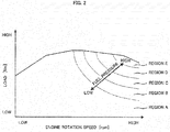
- Fig. 2 is an operation map illustrating the relationship between the engine operation state and the fuel pressure.
- the fuel pressure is set to be higher as the engine rotation speed and the engine load increase. Namely, in an operation region A, the fuel pressure is set to be the lowest, and in an operation region E, the fuel pressure is set to be the highest. With the engine 1, the fuel pressure is changed in a range of several hundreds of kPa in the operation regions A to E.
- the fuel pressure in the operation regions C to E is set to be higher than that of the conventionally-known engine that makes injection of the fuel into the intake passage.
- the fuel pressure is increased at the high engine rotation speed and at the high engine load like this, it is possible to facilitate atomization of the fuel, and to make injection of the predetermined amount of the fuel without leaving the fuel unused.
- the pressure of the fuel supplied to the fuel injection valve 71 and the pressure of the intake air in the intake manifold 51 affect a fuel injection amount of the fuel injection valve 71. Namely, when a differential pressure between the fuel pressure in the fuel injection valve 71 and the intake pressure in the intake manifold 51 increases, the fuel injection from the fuel injection valve 71 can be easily made. On the other hand, when the differential pressure decreases, the fuel injection from the fuel injection valve 71 is difficult.
- the fuel injection control device 100 of the engine 1 is so configured that optimum fuel injection can be performed with regard to the engine operation state.
- the target pulse width is a control parameter that defines a valve-opening time of the fuel injection valve 71 and, as the target pulse width increases, a flow rate of the fuel injected from the fuel injection valve 71 (injection amount) increases.
- the controller 90 is provided with an effective pulse width calculation unit 210 that calculates an effective pulse width Te, an ineffective pulse width calculation unit 220 that calculates an ineffective pulse width Ts, a request pulse width calculation unit 230 that calculates a request pulse width CTI based on the effective pulse width Te, a pulse correction unit 240 that calculates a post-correction request pulse width CTI' by correcting the request pulse width CTI, and a target pulse width setting unit 250 that sets a target pulse width CTIF based on the post-correction request pulse width CTI'.
- the effective pulse width calculation unit 210 calculates the effective pulse width Te based on the intake flow rate, the fuel pressure, and the differential pressure between the fuel pressure and the intake pressure.
- the effective pulse width Te is a parameter for defining a time period during which the fuel injection valve 71 actually opens.
- the effective pulse width calculation unit 210 is composed of various calculation units 211 to 217.
- a basic pulse width calculation unit 211 in the effective pulse width calculation unit 210 calculates a basic pulse width Tp based on an intake flow rate Q detected by the air flow meter 54.
- a multiplier unit 212 calculates a first basic pulse width Tp1 by multiplying the basic pulse width Tp, a target equivalent ratio TTFBYA, and a pulse width correction coefficient Ceva with consideration given to fuel evaporation in the fuel tank 75.
- An adder unit 213 calculates a second basic pulse width Tp2 by adding a pulse width correction coefficient Ct, with consideration given to a transitional operation state such as when accelerating the vehicle, to the first basic pulse width Tp1.
- the second basic pulse width Tp2 is used in a multiplier unit 217 that will be described later.
- a pulse width correction coefficient Cfp with consideration given to a pressure state applied to the fuel injection valve 71, that is, the differential pressure between the fuel pressure and the intake pressure, is calculated by a fuel pressure reference coefficient calculation unit 214, a differential pressure correction coefficient calculation unit 215, and a multiplier unit 216.
- the fuel pressure reference coefficient calculation unit 214 calculates a fuel pressure reference coefficient MK based on a fuel pressure Pf detected by the fuel pressure sensor 76.
- the fuel pressure reference coefficient calculation unit 214 determines the fuel pressure reference coefficient MK by referring to a fuel pressure reference coefficient calculation map of Fig. 4 .
- the fuel pressure reference coefficient calculation map is stored in the ROM of the controller 90.
- the fuel pressure reference coefficient MK is set to be lower as the fuel pressure Pf becomes higher. This is because the flow rate of the fuel injected from the fuel injection valve 71 becomes higher as the fuel pressure Pf becomes higher, and the pulse width (fuel injection time) required for the same intake amount becomes smaller as compared with the case where the fuel pressure is lower.
- the differential pressure correction coefficient calculation unit 215 calculates a differential pressure correction coefficient Cp based on a differential pressure ⁇ P.
- the differential pressure ⁇ P is calculated by a differential pressure calculation unit 260 provided in the controller 90.
- the differential pressure ⁇ P is calculated based on the fuel pressure Pf detected by the fuel pressure sensor 76, and an intake pressure Pm detected by the intake pressure sensor 55. It should be noted that, when the pressure indicated by the fuel pressure sensor 76 or the like is a gage pressure, the differential pressure ⁇ P is calculated based on the atmospheric pressure detected by an atmospheric pressure sensor that is provided separately in the engine 1, the fuel pressure Pf, and the intake pressure Pm.
- the differential pressure correction coefficient calculation unit 215 determines the differential pressure correction coefficient Cp by referring to a differential pressure correction coefficient calculation map of Fig. 5 .
- the differential pressure correction coefficient calculation map is stored in the ROM of the controller 90.
- the differential pressure correction coefficient Cp calculated by the differential pressure correction coefficient calculation unit 215 is set to be lower as the differential pressure ⁇ P becomes higher. This is because, as the differential pressure ⁇ P becomes higher, the fuel injection from the fuel injection valve 71 can be easily made and the fuel injection flow rate becomes higher, and hence the pulse width (fuel injection time) required for the same intake amount becomes smaller as compared with the case where the differential pressure is lower.
- the multiplier unit 216 calculates the pulse width correction coefficient Cfp, with consideration given to the pressure state applied to the fuel injection valve 71, by multiplying the fuel pressure reference coeffcient MK, the differential pressure correction coefficient Cp, and a fixed value mMK that is determined in advance as an eigenvalue for each fuel injection valve 71.
- the multiplier unit 217 calculates the effective pulse width Te by multiplying the second basic pulse width Tp2 that is calculated by the adder unit 213, the pulse width correction coefficient Cfp that is calculated by the multiplier unit 216, and a pulse width correction coefficient C ⁇ that is determined according to a control state of air-fuel ratio feedback control executed based on a detected value of the air-fuel ratio sensor 63.
- the effective pulse width calculation unit 210 calculates the effective pulse width Te by correcting the basic pulse width Tp, calculated from the intake flow rate Q, with the various correction coefficients.
- the effective pulse width calculation unit 210 it is possible to arrange the effective pulse width calculation unit 210 in such a manner that it calculates the effective pulse width Te by multiplying the basic pulse width Tp, the fuel pressure reference coefficient MK calculated based on the fuel pressure Pf, and the differential pressure correction coefficient Cp calculated based on the differential pressure ⁇ P.
- the ineffective pulse width calculation unit 220 in the controller 90 calculates the ineffective pulse width Ts based on the differential pressure ⁇ P calculated by the differential pressure calculation unit 260 and a battery voltage Vb detected by the battery voltage sensor 91.
- the ineffective pulse width Ts is a parameter that represents a response delay from the time when a valve-opening signal is applied to the fuel injection valve 71 until the time when the fuel injection valve 71 actually opens.
- the ineffective pulse width calculation unit 220 determines the ineffective pulse width Ts by referring to an ineffective pulse width calculation map of Fig. 6 .
- the ineffective pulse width calculation map is stored in the ROM of the controller 90.
- a characteristic line illustrating the relationship between the battery voltage Vb and the ineffective pulse width Ts, is defined for each differential pressure ⁇ P.
- the ineffective pulse width Ts is set to be greater as the battery voltage Vb becomes smaller. In the case where the battery voltage Vb is the same, the ineffective pulse width Ts is set to be greater as the differential pressure ⁇ P becomes higher.
- the request pulse width calculation unit 230 calculates the request pulse width CTI by adding the ineffective pulse width Ts to the effective pulse width Te.
- the request pulse width calculation unit 230 can be configured to calculate the effective pulse width Te as the request pulse width, without any change, in the case where the ineffective pulse width Ts can be ignored, such as where the ineffective pulse width Ts is extremely small.
- the pulse correction unit 240 is provided for executing pulse width correction in a low flow rate region, in which the flow rate of the fuel injected from the fuel injection valve 71 is lower than a reference flow rate.
- the reference flow rate is a value determined in advance through experiments and the like, for each fuel injection valve 71.
- the fuel injection valve 71 is controlled to open according to the pulse width, and basically, the pulse width is linearly proportional to the flow rate of the fuel injected from the fuel injection valve 71.
- the pulse width (request pulse width, for example) becomes smaller than a reference value and the fuel flow rate becomes lower than the reference flow rate
- the relationship between the pulse width and the fuel flow rate deviates from the linear relationship as illustrated by a broken line portion of L1 to the nonlinear relationship as illustrated by a solid line portion of L1.
- the fuel injection valve 71 has the nonlinear region like this, but no consideration has been given to an influence of the differential pressure, especially to an influence of variability of the fuel pressure. Namely, the fact that the differential pressure between the fuel pressure and the intake pressure affects the fuel injection amount, with respect to the pulse width, of the fuel injection valve 71 has been disclosed in the conventional art, and the differential pressure between the fuel pressure and the intake pressure has been used for correcting the effective pulse width. However, the differential pressure between the fuel pressure and the intake pressure has not been used for the correction in the nonlinear region of the flow rate of the fuel injected from the fuel injection valve 71.
- a variable width of the intake pressure is about 100 kPa, from an atmospheric pressure to a vacuum, and thus the variable width of the differential pressure is approximately within the range of 100 kPa, unless the fuel pressure is varied actively.
- the influence of the differential pressure is smaller as compared with the level of the flow rate of the fuel injected from the fuel injection valve 71, and hence the influence of the differential pressure has not been recognized as a problem.
- the influence of the differential pressure is not ignorable, because the fuel pressure is changed in the range of several hundreds of kPa in the operation regions and the variations in the differential pressure corresponding to the variations in the fuel pressure are large. Therefore, the correction based on the differential pressure between the fuel pressure and the intake pressure is executed, together with the correction according to the flow rate of the fuel to be injected, as will be described below.
- the calculation of the post-correction pulse width by the pulse width correction is made based on a tangent L2 that passes through the fuel flow rate Q1 and comes in contact with a curved portion of L1 in the nonlinear region.
- the post-correction pulse width CTI' for obtaining the fuel flow rate Q1 can be found by the following expression (1) by using the pre-correction pulse width CTI.
- CTI ′ a c ⁇ CTI + b ⁇ d c
- the coefficient of the first term in the right side in the expression (1) corresponds to a first correction coefficient HOSA that is calculated by the pulse correction unit 240 of Fig. 3
- a coefficient of the second term in the right side corresponds to a second correction coefficient HOSB that is calculated by the pulse correction unit 240.
- the pulse correction unit 240 is composed of a low flow rate region correction coefficient calculation unit 241, and a post-correction request pulse width calculation unit 242.
- the low flow rate region correction coefficient calculation unit 241 calculates the above-described first correction coefficient HOSA and second correction coefficient HOSB, based on the differential pressure ⁇ P calculated by the differential pressure calculation unit 260.
- the fuel pressure is changed in the range of several hundreds of kPa according to the operation state, and the intake pressure also changes according to the operation state, and therefore, the first correction coefficient HOSA and the second correction coefficient HOSB are determined in consideration of the differential pressure ⁇ P between the fuel pressure and the intake pressure.
- the low flow rate region correction coefficient calculation unit 241 calculates the first correction coefficient HOSA by referring to a first correction coefficient calculation map of Fig. 8 .
- the first correction coefficient calculation map is stored in the ROM of the controller 90.
- the first correction coefficient HOSA is set to be lower as the differential pressure ⁇ P becomes higher.
- Fig. 8 shows an example of the first correction coefficient calculation map, and it is possible to use a first correction coefficient calculation map of which characteristics are different from those of Fig. 8 .
- the first correction coefficient calculation map is made conform to each engine 1 through experiments in advance and the like.
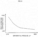
- the low flow rate region correction coefficient calculation unit 241 calculates the second correction coefficient HOSB by referring to a second correction coefficient calculation map of Fig. 9 .
- the second correction coefficient calculation map is stored in the ROM of the controller 90.
- the second correction coefficient HOSB is set to be higher as the differential pressure ⁇ P becomes higher.
- Fig. 9 shows an example of the second correction coefficient calculation map, and it is possible to use a second correction coefficient calculation map of which characteristics are different from those of Fig. 9 .
- the second correction coefficient calculation map is made conform to each engine 1 through experiments in advance and the like.
- the post-correction request pulse width calculation unit 242 in the pulse correction unit 240 calculates the post-correction request pulse width CTI' based on thus-calculated first correction coefficient HOSA and second correction coefficient HOSB, and the request pulse width CTI calculated by the request pulse width calculation unit 230.
- the post-correction request pulse width calculation unit 242 multiplies the request pulse width CTI by the first correction coefficient HOSA, and adds the second correction coefficient HOSB to the multiplied value, to calculate the post-correction request pulse width CTI'.
- the pulse width correction in the low flow rate region is executed by giving consideration to the pressure state applied to the fuel injection valve 71, that is, the differential pressure ⁇ P between the fuel pressure and the intake pressure.
- the controller 90 is further provided with a minimum pulse width calculation unit 270 for calculating a minimum pulse width Tmin that can be set with respect to the fuel injection valve 71 according to the differential pressure ⁇ P.
- the minimum pulse width calculation unit 270 determines the minimum pulse width Tmin by referring to a minimum pulse width calculation map of Fig. 10 .
- the minimum pulse width calculation map is stored in the ROM of the controller 90.
- Fig. 10 shows an example of the minimum pulse width calculation map, and it is possible to use a minimum pulse width calculation map of which characteristics are different from those of Fig. 10 .
- the controller 90 can be realized without the minimum pulse width calculation unit 270.
- the target pulse width setting unit 250 sets the target pulse width CTIF based on the post-correction request pulse width CTI' that is calculated by the post-correction request pulse width calculation unit 242, the request pulse width CTI that is calculated by the request pulse width calculation unit 230, and the minimum pulse width Tmin that is calculated by the minimum pulse width calculation unit 270. Specifically, the target pulse width setting unit 250 sets, as the target pulse width CTIF, the largest value among the post-correction request pulse width CTI', the request pulse width CTI and the minimum pulse width Tmin.
- the fuel injection valve 71 is controlled by thus set target pulse width CTIF, and the fuel is supplied into the intake manifold 51.
- the target pulse width setting unit 250 in the controller 90 sets the target pulse width CTIF based on the request pulse width CTI, the post-correction request pulse width CTI' and the like.
- the target pulse width setting unit 250 can set the target pulse width CTIF based on the post-correction request pulse width CTI' only.
- the fuel injection control device 100 of the engine 1 is provided with the fuel injection valve 71 that injects the fuel into the intake passage according to the target pulse width, and the fuel pump 74 that controls the fuel pressure supplied to the fuel injection valve 71 depending on the engine operation state.
- the request pulse width calculation unit 230 calculates the request pulse width based on the intake flow rate, the pressure of the fuel supplied to the fuel injection valve 71, and the differential pressure between the fuel pressure and the intake pressure inside the intake manifold 51
- the post-correction request pulse width calculation unit 242 calculates the post-correction request pulse width by correcting the request pulse width according to the differential pressure, when injecting the fuel in a flow rate lower than the predetermined reference flow rate.
- the target pulse width setting unit 250 in the fuel injection control device 100 sets the target pulse width based on the post-correction request pulse width. Specifically, the target pulse width setting unit 250 sets, as the target pulse width, the greater one between the post-correction request pulse width and the pre-correction request pulse width.
- the fuel pressure supplied to the fuel injection valve 71 is controlled by the fuel pump 74 according to the engine operation state
- the fuel injection control can be performed in the optimum manner even when the fuel pressure or the intake pressure changes, and deterioration in the fuel consumption performance and the exhaust performance in the low flow rate region can be controlled.
- the pressure of the fuel to be supplied to the fuel injection valve 71 becomes higher as the engine rotation speed becomes faster and the engine load becomes higher with regard to the engine operation state. This makes it possible to facilitate atomization of the fuel, and to make injection of the predetermined amount of the fuel without leaving the fuel unused, even at the high engine rotation speed and the high engine load. As a result of this, it is possible to realize the fuel injection more appropriately according to the engine operation state.
- the fuel injection control device 100 is further provided with the low flow rate region correction coefficient calculation unit 241 that calculates the first correction coefficient and the second correction coefficient, for correcting the request pulse width, based on the differential pressure.
- the post-correction request pulse width calculation unit 242 calculates the post-correction request pulse width by multiplying the request pulse width by the first correction coefficient and adding the second correction coefficient to the multiplied value. As the two correction coefficients are used like this, it is possible to correct the request pulse width with ease and with accuracy.
- the request pulse width calculation unit 230 in the fuel injection control device 100 calculates the request pulse width by adding the effective pulse width that is calculated based on the intake flow rate, the fuel pressure, and the differential pressure, to the ineffective pulse width that is calculated based on the differential pressure and the battery voltage.
- the calculation of the effective pulse width and the ineffective pulse width is carried out by giving consideration to the differential pressure between the pressure of the fuel to be supplied to the fuel injection valve 71 and the pressure of the intake air inside the intake manifold 51, it is possible to realize the fuel injection more appropriately according to the engine operation state
Landscapes
- Engineering & Computer Science (AREA)
- Chemical & Material Sciences (AREA)
- Combustion & Propulsion (AREA)
- Mechanical Engineering (AREA)
- General Engineering & Computer Science (AREA)
- Electrical Control Of Air Or Fuel Supplied To Internal-Combustion Engine (AREA)
- Combined Controls Of Internal Combustion Engines (AREA)
Applications Claiming Priority (1)
| Application Number | Priority Date | Filing Date | Title |
|---|---|---|---|
| PCT/JP2013/074231 WO2015033466A1 (ja) | 2013-09-09 | 2013-09-09 | エンジンの燃料噴射制御装置及びエンジンの燃料噴射制御方法 |
Publications (3)
| Publication Number | Publication Date |
|---|---|
| EP3045702A1 true EP3045702A1 (de) | 2016-07-20 |
| EP3045702A4 EP3045702A4 (de) | 2016-09-21 |
| EP3045702B1 EP3045702B1 (de) | 2018-11-07 |
Family
ID=52627971
Family Applications (1)
| Application Number | Title | Priority Date | Filing Date |
|---|---|---|---|
| EP13892899.9A Active EP3045702B1 (de) | 2013-09-09 | 2013-09-09 | Kraftstoffeinspritzsteuerungsvorrichtung eines motors und kraftstoffeinspritzsteuerungsverfahren eines motors |
Country Status (5)
| Country | Link |
|---|---|
| US (1) | US9719458B2 (de) |
| EP (1) | EP3045702B1 (de) |
| JP (1) | JP6037020B2 (de) |
| CN (1) | CN105579691B (de) |
| WO (1) | WO2015033466A1 (de) |
Cited By (1)
| Publication number | Priority date | Publication date | Assignee | Title |
|---|---|---|---|---|
| EP3361079A1 (de) * | 2017-02-13 | 2018-08-15 | Toyota Jidosha Kabushiki Kaisha | Kraftstoffeinspritzungssteuergerät und kraftstoffeinspritzungssteuerungsverfahren für verbrennungsmotor |
Families Citing this family (6)
| Publication number | Priority date | Publication date | Assignee | Title |
|---|---|---|---|---|
| EP3045702B1 (de) * | 2013-09-09 | 2018-11-07 | Nissan Motor Co., Ltd | Kraftstoffeinspritzsteuerungsvorrichtung eines motors und kraftstoffeinspritzsteuerungsverfahren eines motors |
| US10859027B2 (en) * | 2017-10-03 | 2020-12-08 | Polaris Industries Inc. | Method and system for controlling an engine |
| KR102406014B1 (ko) * | 2017-12-27 | 2022-06-08 | 현대자동차주식회사 | Gdi 인젝터 정적유량 편차 보정 방법 및 그 시스템 |
| EP3438622B1 (de) * | 2018-06-25 | 2022-08-03 | Komatsu Ltd. | System zur messung des kraftstoffverbrauchs eines nutzfahrzeugs und verfahren zum messen des kraftstoffverbrauchs für ein nutzfahrzeug |
| JP7559744B2 (ja) * | 2021-12-13 | 2024-10-02 | トヨタ自動車株式会社 | 内燃機関システム |
| CN116085134B (zh) * | 2023-02-24 | 2024-06-04 | 一汽解放汽车有限公司 | 发动机燃料喷射控制方法、装置、设备、介质和产品 |
Family Cites Families (25)
| Publication number | Priority date | Publication date | Assignee | Title |
|---|---|---|---|---|
| JPS5949739U (ja) | 1982-09-24 | 1984-04-02 | 日本電子機器株式会社 | 内燃機関の電子制御燃料噴射装置 |
| JP3194670B2 (ja) * | 1994-06-30 | 2001-07-30 | 三菱電機株式会社 | 内燃機関の電子制御装置 |
| JP3189143B2 (ja) * | 1994-09-19 | 2001-07-16 | 株式会社ユニシアジェックス | 内燃機関の燃料供給装置 |
| JP3521504B2 (ja) | 1994-09-30 | 2004-04-19 | マツダ株式会社 | エンジンの燃料供給制御装置 |
| JP3154038B2 (ja) * | 1995-01-06 | 2001-04-09 | 株式会社ユニシアジェックス | 内燃機関の吸気圧力推定装置及び燃料供給装置 |
| JPH08193538A (ja) * | 1995-01-18 | 1996-07-30 | Nippondenso Co Ltd | 内燃機関の燃料制御装置 |
| JPH09209803A (ja) | 1996-02-06 | 1997-08-12 | Unisia Jecs Corp | 内燃機関の燃料噴射制御装置 |
| DE19804677C2 (de) | 1998-02-06 | 2000-03-23 | Audi Ag | Verfahren zum Betreiben einer Brennkraftmaschine |
| JP3559890B2 (ja) | 1998-06-01 | 2004-09-02 | 日産自動車株式会社 | 燃料噴射弁の選別方法 |
| JP2001152992A (ja) * | 1999-11-30 | 2001-06-05 | Unisia Jecs Corp | エンジンの燃料圧力制御装置 |
| JP3829035B2 (ja) * | 1999-11-30 | 2006-10-04 | 株式会社日立製作所 | エンジンの燃料圧力制御装置 |
| DE60236305D1 (de) * | 2001-07-12 | 2010-06-17 | Yamaha Motor Co Ltd | Viertaktmotorsteuervorrichtung und -steuerverfahren |
| JP2003049686A (ja) * | 2001-08-08 | 2003-02-21 | Toyota Motor Corp | 内燃機関の燃料噴射量制御装置 |
| JP2003286879A (ja) * | 2002-03-27 | 2003-10-10 | Mazda Motor Corp | ディーゼルエンジンの燃焼制御装置 |
| JP3786262B2 (ja) * | 2002-04-16 | 2006-06-14 | 三菱電機株式会社 | 自動車用燃料供給装置 |
| JP4085900B2 (ja) * | 2003-07-08 | 2008-05-14 | 日産自動車株式会社 | 筒内直接噴射式火花点火エンジンの燃料噴射制御装置 |
| JP2006329110A (ja) * | 2005-05-27 | 2006-12-07 | Toyota Motor Corp | 内燃機関の制御装置 |
| CA2538984C (en) * | 2006-03-10 | 2007-11-06 | Westport Research Inc. | Method of accurately metering a gaseous fuel that is injected directly into a combustion chamber of an internal combustion engine |
| JP2007332783A (ja) * | 2006-06-12 | 2007-12-27 | Nissan Motor Co Ltd | エンジンの燃料供給方法及びエンジンの燃料供給装置 |
| CN101285431B (zh) * | 2007-04-09 | 2010-04-14 | 山东申普汽车控制技术有限公司 | 组合脉谱对发动机控制的方法 |
| JP4905291B2 (ja) * | 2007-08-09 | 2012-03-28 | 日産自動車株式会社 | 空燃比制御装置 |
| JP5387431B2 (ja) * | 2010-02-04 | 2014-01-15 | スズキ株式会社 | 車両用エンジンのガス燃料噴射制御装置 |
| US8452520B2 (en) | 2010-06-01 | 2013-05-28 | GM Global Technology Operations LLC | Control system and method for low quantity fuel injection |
| JP5727395B2 (ja) * | 2012-01-16 | 2015-06-03 | 日立オートモティブシステムズ株式会社 | 内燃機関の制御装置 |
| EP3045702B1 (de) * | 2013-09-09 | 2018-11-07 | Nissan Motor Co., Ltd | Kraftstoffeinspritzsteuerungsvorrichtung eines motors und kraftstoffeinspritzsteuerungsverfahren eines motors |
-
2013
- 2013-09-09 EP EP13892899.9A patent/EP3045702B1/de active Active
- 2013-09-09 CN CN201380079713.5A patent/CN105579691B/zh active Active
- 2013-09-09 JP JP2015535260A patent/JP6037020B2/ja active Active
- 2013-09-09 US US14/917,288 patent/US9719458B2/en active Active
- 2013-09-09 WO PCT/JP2013/074231 patent/WO2015033466A1/ja not_active Ceased
Cited By (2)
| Publication number | Priority date | Publication date | Assignee | Title |
|---|---|---|---|---|
| EP3361079A1 (de) * | 2017-02-13 | 2018-08-15 | Toyota Jidosha Kabushiki Kaisha | Kraftstoffeinspritzungssteuergerät und kraftstoffeinspritzungssteuerungsverfahren für verbrennungsmotor |
| US10428758B2 (en) | 2017-02-13 | 2019-10-01 | Toyota Jidosha Kabushiki Kaisha | Fuel injection controller and fuel injection control method for internal combustion engine |
Also Published As
| Publication number | Publication date |
|---|---|
| JP6037020B2 (ja) | 2016-11-30 |
| EP3045702A4 (de) | 2016-09-21 |
| JPWO2015033466A1 (ja) | 2017-03-02 |
| CN105579691B (zh) | 2018-08-10 |
| EP3045702B1 (de) | 2018-11-07 |
| CN105579691A (zh) | 2016-05-11 |
| US9719458B2 (en) | 2017-08-01 |
| WO2015033466A1 (ja) | 2015-03-12 |
| US20160215725A1 (en) | 2016-07-28 |
Similar Documents
| Publication | Publication Date | Title |
|---|---|---|
| EP3045702B1 (de) | Kraftstoffeinspritzsteuerungsvorrichtung eines motors und kraftstoffeinspritzsteuerungsverfahren eines motors | |
| EP2142781B1 (de) | Steuerungsvorrichtung für einen verbrennungsmotor | |
| US7669579B2 (en) | Method for the lambda and torque control of an internal combustion engine and program algorithm | |
| EP3029307B1 (de) | Steuerungsvorrichtung für verbrennungsmotor | |
| KR100288519B1 (ko) | 내연기관의 흡기 공기 통로로 퍼지된 기화 연료의 농도를 평가하기 위한 장치 및 방법 | |
| US9670863B2 (en) | Apparatus and method for controlling internal-combustion engine | |
| JP4439021B2 (ja) | エンジンの制御方法 | |
| KR20040031650A (ko) | 바이퓨얼 내연기관의 연료분사제어장치 | |
| JP6315666B2 (ja) | エンジンの燃料噴射制御装置 | |
| KR102750541B1 (ko) | 차량의 퍼지 제어 장치 및 방법 | |
| EP1643109B1 (de) | Luft-Kraftstoffverhältnis-Regelsystem für eine Brennkraftmaschine | |
| EP1403504A2 (de) | Vorrichtung und verfahren zur regelung des entlüftungsdurchflusses einer brennkraftmaschine | |
| US9932923B2 (en) | Abnormality determination apparatus | |
| US9732696B2 (en) | Control device for internal combustion engine and control method for internal combustion engine | |
| JP4687431B2 (ja) | 内燃機関の排気浄化装置 | |
| JP2020007992A (ja) | 内燃機関の制御装置及び診断方法 | |
| US9316179B2 (en) | Secondary air supply device for internal combustion engine | |
| EP1870587A1 (de) | Vorrichtung zur steuerung der kraftstoffeinspritzung in dieselmotoren | |
| JP2013072415A (ja) | 内燃機関の制御装置及び制御方法 | |
| JP6489298B2 (ja) | 内燃機関の燃料噴射制御装置 | |
| US10316787B2 (en) | Fuel supply device for internal combustion engine | |
| JP4329610B2 (ja) | 内燃機関の燃料噴射量制御装置 | |
| JP2018141383A (ja) | エンジンの制御装置 | |
| JP2017203417A (ja) | エンジンの燃料噴射装置 | |
| JP2010133387A (ja) | 内燃機関の制御装置 |
Legal Events
| Date | Code | Title | Description |
|---|---|---|---|
| PUAI | Public reference made under article 153(3) epc to a published international application that has entered the european phase |
Free format text: ORIGINAL CODE: 0009012 |
|
| 17P | Request for examination filed |
Effective date: 20160321 |
|
| AK | Designated contracting states |
Kind code of ref document: A1 Designated state(s): AL AT BE BG CH CY CZ DE DK EE ES FI FR GB GR HR HU IE IS IT LI LT LU LV MC MK MT NL NO PL PT RO RS SE SI SK SM TR |
|
| AX | Request for extension of the european patent |
Extension state: BA ME |
|
| A4 | Supplementary search report drawn up and despatched |
Effective date: 20160822 |
|
| RIC1 | Information provided on ipc code assigned before grant |
Ipc: F02D 41/04 20060101AFI20160816BHEP Ipc: F02M 69/00 20060101ALI20160816BHEP Ipc: F02D 41/18 20060101ALI20160816BHEP Ipc: F02D 41/34 20060101ALI20160816BHEP Ipc: F02D 41/00 20060101ALI20160816BHEP |
|
| DAX | Request for extension of the european patent (deleted) | ||
| GRAP | Despatch of communication of intention to grant a patent |
Free format text: ORIGINAL CODE: EPIDOSNIGR1 |
|
| STAA | Information on the status of an ep patent application or granted ep patent |
Free format text: STATUS: GRANT OF PATENT IS INTENDED |
|
| INTG | Intention to grant announced |
Effective date: 20180522 |
|
| RIN1 | Information on inventor provided before grant (corrected) |
Inventor name: TERAUCHI, KAZUMICHI Inventor name: YOKOYA, SHIGEHIRO Inventor name: KATAYAMA, TAKATSUGU Inventor name: AMANO, AKIO |
|
| GRAS | Grant fee paid |
Free format text: ORIGINAL CODE: EPIDOSNIGR3 |
|
| GRAA | (expected) grant |
Free format text: ORIGINAL CODE: 0009210 |
|
| STAA | Information on the status of an ep patent application or granted ep patent |
Free format text: STATUS: THE PATENT HAS BEEN GRANTED |
|
| AK | Designated contracting states |
Kind code of ref document: B1 Designated state(s): AL AT BE BG CH CY CZ DE DK EE ES FI FR GB GR HR HU IE IS IT LI LT LU LV MC MK MT NL NO PL PT RO RS SE SI SK SM TR |
|
| REG | Reference to a national code |
Ref country code: GB Ref legal event code: FG4D |
|
| REG | Reference to a national code |
Ref country code: CH Ref legal event code: EP Ref country code: AT Ref legal event code: REF Ref document number: 1062333 Country of ref document: AT Kind code of ref document: T Effective date: 20181115 |
|
| REG | Reference to a national code |
Ref country code: DE Ref legal event code: R096 Ref document number: 602013046522 Country of ref document: DE |
|
| REG | Reference to a national code |
Ref country code: IE Ref legal event code: FG4D |
|
| REG | Reference to a national code |
Ref country code: NL Ref legal event code: MP Effective date: 20181107 |
|
| REG | Reference to a national code |
Ref country code: LT Ref legal event code: MG4D |
|
| REG | Reference to a national code |
Ref country code: AT Ref legal event code: MK05 Ref document number: 1062333 Country of ref document: AT Kind code of ref document: T Effective date: 20181107 |
|
| PG25 | Lapsed in a contracting state [announced via postgrant information from national office to epo] |
Ref country code: HR Free format text: LAPSE BECAUSE OF FAILURE TO SUBMIT A TRANSLATION OF THE DESCRIPTION OR TO PAY THE FEE WITHIN THE PRESCRIBED TIME-LIMIT Effective date: 20181107 Ref country code: NO Free format text: LAPSE BECAUSE OF FAILURE TO SUBMIT A TRANSLATION OF THE DESCRIPTION OR TO PAY THE FEE WITHIN THE PRESCRIBED TIME-LIMIT Effective date: 20190207 Ref country code: BG Free format text: LAPSE BECAUSE OF FAILURE TO SUBMIT A TRANSLATION OF THE DESCRIPTION OR TO PAY THE FEE WITHIN THE PRESCRIBED TIME-LIMIT Effective date: 20190207 Ref country code: LT Free format text: LAPSE BECAUSE OF FAILURE TO SUBMIT A TRANSLATION OF THE DESCRIPTION OR TO PAY THE FEE WITHIN THE PRESCRIBED TIME-LIMIT Effective date: 20181107 Ref country code: FI Free format text: LAPSE BECAUSE OF FAILURE TO SUBMIT A TRANSLATION OF THE DESCRIPTION OR TO PAY THE FEE WITHIN THE PRESCRIBED TIME-LIMIT Effective date: 20181107 Ref country code: LV Free format text: LAPSE BECAUSE OF FAILURE TO SUBMIT A TRANSLATION OF THE DESCRIPTION OR TO PAY THE FEE WITHIN THE PRESCRIBED TIME-LIMIT Effective date: 20181107 Ref country code: ES Free format text: LAPSE BECAUSE OF FAILURE TO SUBMIT A TRANSLATION OF THE DESCRIPTION OR TO PAY THE FEE WITHIN THE PRESCRIBED TIME-LIMIT Effective date: 20181107 Ref country code: IS Free format text: LAPSE BECAUSE OF FAILURE TO SUBMIT A TRANSLATION OF THE DESCRIPTION OR TO PAY THE FEE WITHIN THE PRESCRIBED TIME-LIMIT Effective date: 20190307 Ref country code: AT Free format text: LAPSE BECAUSE OF FAILURE TO SUBMIT A TRANSLATION OF THE DESCRIPTION OR TO PAY THE FEE WITHIN THE PRESCRIBED TIME-LIMIT Effective date: 20181107 |
|
| PG25 | Lapsed in a contracting state [announced via postgrant information from national office to epo] |
Ref country code: RS Free format text: LAPSE BECAUSE OF FAILURE TO SUBMIT A TRANSLATION OF THE DESCRIPTION OR TO PAY THE FEE WITHIN THE PRESCRIBED TIME-LIMIT Effective date: 20181107 Ref country code: PT Free format text: LAPSE BECAUSE OF FAILURE TO SUBMIT A TRANSLATION OF THE DESCRIPTION OR TO PAY THE FEE WITHIN THE PRESCRIBED TIME-LIMIT Effective date: 20190307 Ref country code: GR Free format text: LAPSE BECAUSE OF FAILURE TO SUBMIT A TRANSLATION OF THE DESCRIPTION OR TO PAY THE FEE WITHIN THE PRESCRIBED TIME-LIMIT Effective date: 20190208 Ref country code: AL Free format text: LAPSE BECAUSE OF FAILURE TO SUBMIT A TRANSLATION OF THE DESCRIPTION OR TO PAY THE FEE WITHIN THE PRESCRIBED TIME-LIMIT Effective date: 20181107 Ref country code: NL Free format text: LAPSE BECAUSE OF FAILURE TO SUBMIT A TRANSLATION OF THE DESCRIPTION OR TO PAY THE FEE WITHIN THE PRESCRIBED TIME-LIMIT Effective date: 20181107 Ref country code: SE Free format text: LAPSE BECAUSE OF FAILURE TO SUBMIT A TRANSLATION OF THE DESCRIPTION OR TO PAY THE FEE WITHIN THE PRESCRIBED TIME-LIMIT Effective date: 20181107 |
|
| PG25 | Lapsed in a contracting state [announced via postgrant information from national office to epo] |
Ref country code: PL Free format text: LAPSE BECAUSE OF FAILURE TO SUBMIT A TRANSLATION OF THE DESCRIPTION OR TO PAY THE FEE WITHIN THE PRESCRIBED TIME-LIMIT Effective date: 20181107 Ref country code: DK Free format text: LAPSE BECAUSE OF FAILURE TO SUBMIT A TRANSLATION OF THE DESCRIPTION OR TO PAY THE FEE WITHIN THE PRESCRIBED TIME-LIMIT Effective date: 20181107 Ref country code: IT Free format text: LAPSE BECAUSE OF FAILURE TO SUBMIT A TRANSLATION OF THE DESCRIPTION OR TO PAY THE FEE WITHIN THE PRESCRIBED TIME-LIMIT Effective date: 20181107 Ref country code: CZ Free format text: LAPSE BECAUSE OF FAILURE TO SUBMIT A TRANSLATION OF THE DESCRIPTION OR TO PAY THE FEE WITHIN THE PRESCRIBED TIME-LIMIT Effective date: 20181107 |
|
| REG | Reference to a national code |
Ref country code: DE Ref legal event code: R097 Ref document number: 602013046522 Country of ref document: DE |
|
| PG25 | Lapsed in a contracting state [announced via postgrant information from national office to epo] |
Ref country code: SK Free format text: LAPSE BECAUSE OF FAILURE TO SUBMIT A TRANSLATION OF THE DESCRIPTION OR TO PAY THE FEE WITHIN THE PRESCRIBED TIME-LIMIT Effective date: 20181107 Ref country code: SM Free format text: LAPSE BECAUSE OF FAILURE TO SUBMIT A TRANSLATION OF THE DESCRIPTION OR TO PAY THE FEE WITHIN THE PRESCRIBED TIME-LIMIT Effective date: 20181107 Ref country code: EE Free format text: LAPSE BECAUSE OF FAILURE TO SUBMIT A TRANSLATION OF THE DESCRIPTION OR TO PAY THE FEE WITHIN THE PRESCRIBED TIME-LIMIT Effective date: 20181107 Ref country code: RO Free format text: LAPSE BECAUSE OF FAILURE TO SUBMIT A TRANSLATION OF THE DESCRIPTION OR TO PAY THE FEE WITHIN THE PRESCRIBED TIME-LIMIT Effective date: 20181107 |
|
| PLBE | No opposition filed within time limit |
Free format text: ORIGINAL CODE: 0009261 |
|
| STAA | Information on the status of an ep patent application or granted ep patent |
Free format text: STATUS: NO OPPOSITION FILED WITHIN TIME LIMIT |
|
| 26N | No opposition filed |
Effective date: 20190808 |
|
| PG25 | Lapsed in a contracting state [announced via postgrant information from national office to epo] |
Ref country code: SI Free format text: LAPSE BECAUSE OF FAILURE TO SUBMIT A TRANSLATION OF THE DESCRIPTION OR TO PAY THE FEE WITHIN THE PRESCRIBED TIME-LIMIT Effective date: 20181107 |
|
| PG25 | Lapsed in a contracting state [announced via postgrant information from national office to epo] |
Ref country code: TR Free format text: LAPSE BECAUSE OF FAILURE TO SUBMIT A TRANSLATION OF THE DESCRIPTION OR TO PAY THE FEE WITHIN THE PRESCRIBED TIME-LIMIT Effective date: 20181107 |
|
| PG25 | Lapsed in a contracting state [announced via postgrant information from national office to epo] |
Ref country code: MC Free format text: LAPSE BECAUSE OF FAILURE TO SUBMIT A TRANSLATION OF THE DESCRIPTION OR TO PAY THE FEE WITHIN THE PRESCRIBED TIME-LIMIT Effective date: 20181107 |
|
| REG | Reference to a national code |
Ref country code: CH Ref legal event code: PL |
|
| PG25 | Lapsed in a contracting state [announced via postgrant information from national office to epo] |
Ref country code: IE Free format text: LAPSE BECAUSE OF NON-PAYMENT OF DUE FEES Effective date: 20190909 Ref country code: LI Free format text: LAPSE BECAUSE OF NON-PAYMENT OF DUE FEES Effective date: 20190930 Ref country code: LU Free format text: LAPSE BECAUSE OF NON-PAYMENT OF DUE FEES Effective date: 20190909 Ref country code: CH Free format text: LAPSE BECAUSE OF NON-PAYMENT OF DUE FEES Effective date: 20190930 |
|
| REG | Reference to a national code |
Ref country code: BE Ref legal event code: MM Effective date: 20190930 |
|
| PG25 | Lapsed in a contracting state [announced via postgrant information from national office to epo] |
Ref country code: BE Free format text: LAPSE BECAUSE OF NON-PAYMENT OF DUE FEES Effective date: 20190930 |
|
| PG25 | Lapsed in a contracting state [announced via postgrant information from national office to epo] |
Ref country code: CY Free format text: LAPSE BECAUSE OF FAILURE TO SUBMIT A TRANSLATION OF THE DESCRIPTION OR TO PAY THE FEE WITHIN THE PRESCRIBED TIME-LIMIT Effective date: 20181107 |
|
| PG25 | Lapsed in a contracting state [announced via postgrant information from national office to epo] |
Ref country code: MT Free format text: LAPSE BECAUSE OF FAILURE TO SUBMIT A TRANSLATION OF THE DESCRIPTION OR TO PAY THE FEE WITHIN THE PRESCRIBED TIME-LIMIT Effective date: 20181107 Ref country code: HU Free format text: LAPSE BECAUSE OF FAILURE TO SUBMIT A TRANSLATION OF THE DESCRIPTION OR TO PAY THE FEE WITHIN THE PRESCRIBED TIME-LIMIT; INVALID AB INITIO Effective date: 20130909 |
|
| PG25 | Lapsed in a contracting state [announced via postgrant information from national office to epo] |
Ref country code: MK Free format text: LAPSE BECAUSE OF FAILURE TO SUBMIT A TRANSLATION OF THE DESCRIPTION OR TO PAY THE FEE WITHIN THE PRESCRIBED TIME-LIMIT Effective date: 20181107 |
|
| PGFP | Annual fee paid to national office [announced via postgrant information from national office to epo] |
Ref country code: DE Payment date: 20250820 Year of fee payment: 13 |
|
| PGFP | Annual fee paid to national office [announced via postgrant information from national office to epo] |
Ref country code: GB Payment date: 20250822 Year of fee payment: 13 |
|
| PGFP | Annual fee paid to national office [announced via postgrant information from national office to epo] |
Ref country code: FR Payment date: 20250821 Year of fee payment: 13 |