EP3045338B1 - Ölzuleitungsrohr mit hervorragender beständigkeit gegen salzkorrosion - Google Patents
Ölzuleitungsrohr mit hervorragender beständigkeit gegen salzkorrosion Download PDFInfo
- Publication number
- EP3045338B1 EP3045338B1 EP14844177.7A EP14844177A EP3045338B1 EP 3045338 B1 EP3045338 B1 EP 3045338B1 EP 14844177 A EP14844177 A EP 14844177A EP 3045338 B1 EP3045338 B1 EP 3045338B1
- Authority
- EP
- European Patent Office
- Prior art keywords
- stainless steel
- aluminized
- gap
- steel pipe
- metal fitting
- Prior art date
- Legal status (The legal status is an assumption and is not a legal conclusion. Google has not performed a legal analysis and makes no representation as to the accuracy of the status listed.)
- Active
Links
Images


Classifications
-
- C—CHEMISTRY; METALLURGY
- C22—METALLURGY; FERROUS OR NON-FERROUS ALLOYS; TREATMENT OF ALLOYS OR NON-FERROUS METALS
- C22C—ALLOYS
- C22C38/00—Ferrous alloys, e.g. steel alloys
- C22C38/60—Ferrous alloys, e.g. steel alloys containing lead, selenium, tellurium, or antimony, or more than 0.04% by weight of sulfur
-
- B—PERFORMING OPERATIONS; TRANSPORTING
- B32—LAYERED PRODUCTS
- B32B—LAYERED PRODUCTS, i.e. PRODUCTS BUILT-UP OF STRATA OF FLAT OR NON-FLAT, e.g. CELLULAR OR HONEYCOMB, FORM
- B32B15/00—Layered products comprising a layer of metal
- B32B15/01—Layered products comprising a layer of metal all layers being exclusively metallic
- B32B15/012—Layered products comprising a layer of metal all layers being exclusively metallic one layer being formed of an iron alloy or steel, another layer being formed of aluminium or an aluminium alloy
-
- B—PERFORMING OPERATIONS; TRANSPORTING
- B60—VEHICLES IN GENERAL
- B60K—ARRANGEMENT OR MOUNTING OF PROPULSION UNITS OR OF TRANSMISSIONS IN VEHICLES; ARRANGEMENT OR MOUNTING OF PLURAL DIVERSE PRIME-MOVERS IN VEHICLES; AUXILIARY DRIVES FOR VEHICLES; INSTRUMENTATION OR DASHBOARDS FOR VEHICLES; ARRANGEMENTS IN CONNECTION WITH COOLING, AIR INTAKE, GAS EXHAUST OR FUEL SUPPLY OF PROPULSION UNITS IN VEHICLES
- B60K15/00—Arrangement in connection with fuel supply of combustion engines or other fuel consuming energy converters, e.g. fuel cells; Mounting or construction of fuel tanks
- B60K15/03—Fuel tanks
- B60K15/04—Tank inlets
-
- C—CHEMISTRY; METALLURGY
- C22—METALLURGY; FERROUS OR NON-FERROUS ALLOYS; TREATMENT OF ALLOYS OR NON-FERROUS METALS
- C22C—ALLOYS
- C22C38/00—Ferrous alloys, e.g. steel alloys
-
- C—CHEMISTRY; METALLURGY
- C22—METALLURGY; FERROUS OR NON-FERROUS ALLOYS; TREATMENT OF ALLOYS OR NON-FERROUS METALS
- C22C—ALLOYS
- C22C38/00—Ferrous alloys, e.g. steel alloys
- C22C38/001—Ferrous alloys, e.g. steel alloys containing N
-
- C—CHEMISTRY; METALLURGY
- C22—METALLURGY; FERROUS OR NON-FERROUS ALLOYS; TREATMENT OF ALLOYS OR NON-FERROUS METALS
- C22C—ALLOYS
- C22C38/00—Ferrous alloys, e.g. steel alloys
- C22C38/002—Ferrous alloys, e.g. steel alloys containing In, Mg, or other elements not provided for in one single group C22C38/001 - C22C38/60
-
- C—CHEMISTRY; METALLURGY
- C22—METALLURGY; FERROUS OR NON-FERROUS ALLOYS; TREATMENT OF ALLOYS OR NON-FERROUS METALS
- C22C—ALLOYS
- C22C38/00—Ferrous alloys, e.g. steel alloys
- C22C38/004—Very low carbon steels, i.e. having a carbon content of less than 0,01%
-
- C—CHEMISTRY; METALLURGY
- C22—METALLURGY; FERROUS OR NON-FERROUS ALLOYS; TREATMENT OF ALLOYS OR NON-FERROUS METALS
- C22C—ALLOYS
- C22C38/00—Ferrous alloys, e.g. steel alloys
- C22C38/008—Ferrous alloys, e.g. steel alloys containing tin
-
- C—CHEMISTRY; METALLURGY
- C22—METALLURGY; FERROUS OR NON-FERROUS ALLOYS; TREATMENT OF ALLOYS OR NON-FERROUS METALS
- C22C—ALLOYS
- C22C38/00—Ferrous alloys, e.g. steel alloys
- C22C38/02—Ferrous alloys, e.g. steel alloys containing silicon
-
- C—CHEMISTRY; METALLURGY
- C22—METALLURGY; FERROUS OR NON-FERROUS ALLOYS; TREATMENT OF ALLOYS OR NON-FERROUS METALS
- C22C—ALLOYS
- C22C38/00—Ferrous alloys, e.g. steel alloys
- C22C38/04—Ferrous alloys, e.g. steel alloys containing manganese
-
- C—CHEMISTRY; METALLURGY
- C22—METALLURGY; FERROUS OR NON-FERROUS ALLOYS; TREATMENT OF ALLOYS OR NON-FERROUS METALS
- C22C—ALLOYS
- C22C38/00—Ferrous alloys, e.g. steel alloys
- C22C38/06—Ferrous alloys, e.g. steel alloys containing aluminium
-
- C—CHEMISTRY; METALLURGY
- C22—METALLURGY; FERROUS OR NON-FERROUS ALLOYS; TREATMENT OF ALLOYS OR NON-FERROUS METALS
- C22C—ALLOYS
- C22C38/00—Ferrous alloys, e.g. steel alloys
- C22C38/18—Ferrous alloys, e.g. steel alloys containing chromium
- C22C38/20—Ferrous alloys, e.g. steel alloys containing chromium with copper
-
- C—CHEMISTRY; METALLURGY
- C22—METALLURGY; FERROUS OR NON-FERROUS ALLOYS; TREATMENT OF ALLOYS OR NON-FERROUS METALS
- C22C—ALLOYS
- C22C38/00—Ferrous alloys, e.g. steel alloys
- C22C38/18—Ferrous alloys, e.g. steel alloys containing chromium
- C22C38/22—Ferrous alloys, e.g. steel alloys containing chromium with molybdenum or tungsten
-
- C—CHEMISTRY; METALLURGY
- C22—METALLURGY; FERROUS OR NON-FERROUS ALLOYS; TREATMENT OF ALLOYS OR NON-FERROUS METALS
- C22C—ALLOYS
- C22C38/00—Ferrous alloys, e.g. steel alloys
- C22C38/18—Ferrous alloys, e.g. steel alloys containing chromium
- C22C38/24—Ferrous alloys, e.g. steel alloys containing chromium with vanadium
-
- C—CHEMISTRY; METALLURGY
- C22—METALLURGY; FERROUS OR NON-FERROUS ALLOYS; TREATMENT OF ALLOYS OR NON-FERROUS METALS
- C22C—ALLOYS
- C22C38/00—Ferrous alloys, e.g. steel alloys
- C22C38/18—Ferrous alloys, e.g. steel alloys containing chromium
- C22C38/26—Ferrous alloys, e.g. steel alloys containing chromium with niobium or tantalum
-
- C—CHEMISTRY; METALLURGY
- C22—METALLURGY; FERROUS OR NON-FERROUS ALLOYS; TREATMENT OF ALLOYS OR NON-FERROUS METALS
- C22C—ALLOYS
- C22C38/00—Ferrous alloys, e.g. steel alloys
- C22C38/18—Ferrous alloys, e.g. steel alloys containing chromium
- C22C38/28—Ferrous alloys, e.g. steel alloys containing chromium with titanium or zirconium
-
- C—CHEMISTRY; METALLURGY
- C22—METALLURGY; FERROUS OR NON-FERROUS ALLOYS; TREATMENT OF ALLOYS OR NON-FERROUS METALS
- C22C—ALLOYS
- C22C38/00—Ferrous alloys, e.g. steel alloys
- C22C38/18—Ferrous alloys, e.g. steel alloys containing chromium
- C22C38/30—Ferrous alloys, e.g. steel alloys containing chromium with cobalt
-
- C—CHEMISTRY; METALLURGY
- C22—METALLURGY; FERROUS OR NON-FERROUS ALLOYS; TREATMENT OF ALLOYS OR NON-FERROUS METALS
- C22C—ALLOYS
- C22C38/00—Ferrous alloys, e.g. steel alloys
- C22C38/18—Ferrous alloys, e.g. steel alloys containing chromium
- C22C38/32—Ferrous alloys, e.g. steel alloys containing chromium with boron
-
- C—CHEMISTRY; METALLURGY
- C22—METALLURGY; FERROUS OR NON-FERROUS ALLOYS; TREATMENT OF ALLOYS OR NON-FERROUS METALS
- C22C—ALLOYS
- C22C38/00—Ferrous alloys, e.g. steel alloys
- C22C38/18—Ferrous alloys, e.g. steel alloys containing chromium
- C22C38/40—Ferrous alloys, e.g. steel alloys containing chromium with nickel
- C22C38/48—Ferrous alloys, e.g. steel alloys containing chromium with nickel with niobium or tantalum
-
- C—CHEMISTRY; METALLURGY
- C22—METALLURGY; FERROUS OR NON-FERROUS ALLOYS; TREATMENT OF ALLOYS OR NON-FERROUS METALS
- C22C—ALLOYS
- C22C38/00—Ferrous alloys, e.g. steel alloys
- C22C38/18—Ferrous alloys, e.g. steel alloys containing chromium
- C22C38/40—Ferrous alloys, e.g. steel alloys containing chromium with nickel
- C22C38/50—Ferrous alloys, e.g. steel alloys containing chromium with nickel with titanium or zirconium
-
- C—CHEMISTRY; METALLURGY
- C22—METALLURGY; FERROUS OR NON-FERROUS ALLOYS; TREATMENT OF ALLOYS OR NON-FERROUS METALS
- C22C—ALLOYS
- C22C38/00—Ferrous alloys, e.g. steel alloys
- C22C38/18—Ferrous alloys, e.g. steel alloys containing chromium
- C22C38/40—Ferrous alloys, e.g. steel alloys containing chromium with nickel
- C22C38/54—Ferrous alloys, e.g. steel alloys containing chromium with nickel with boron
-
- C—CHEMISTRY; METALLURGY
- C23—COATING METALLIC MATERIAL; COATING MATERIAL WITH METALLIC MATERIAL; CHEMICAL SURFACE TREATMENT; DIFFUSION TREATMENT OF METALLIC MATERIAL; COATING BY VACUUM EVAPORATION, BY SPUTTERING, BY ION IMPLANTATION OR BY CHEMICAL VAPOUR DEPOSITION, IN GENERAL; INHIBITING CORROSION OF METALLIC MATERIAL OR INCRUSTATION IN GENERAL
- C23C—COATING METALLIC MATERIAL; COATING MATERIAL WITH METALLIC MATERIAL; SURFACE TREATMENT OF METALLIC MATERIAL BY DIFFUSION INTO THE SURFACE, BY CHEMICAL CONVERSION OR SUBSTITUTION; COATING BY VACUUM EVAPORATION, BY SPUTTERING, BY ION IMPLANTATION OR BY CHEMICAL VAPOUR DEPOSITION, IN GENERAL
- C23C2/00—Hot-dipping or immersion processes for applying the coating material in the molten state without affecting the shape; Apparatus therefor
- C23C2/04—Hot-dipping or immersion processes for applying the coating material in the molten state without affecting the shape; Apparatus therefor characterised by the coating material
- C23C2/12—Aluminium or alloys based thereon
-
- C—CHEMISTRY; METALLURGY
- C23—COATING METALLIC MATERIAL; COATING MATERIAL WITH METALLIC MATERIAL; CHEMICAL SURFACE TREATMENT; DIFFUSION TREATMENT OF METALLIC MATERIAL; COATING BY VACUUM EVAPORATION, BY SPUTTERING, BY ION IMPLANTATION OR BY CHEMICAL VAPOUR DEPOSITION, IN GENERAL; INHIBITING CORROSION OF METALLIC MATERIAL OR INCRUSTATION IN GENERAL
- C23C—COATING METALLIC MATERIAL; COATING MATERIAL WITH METALLIC MATERIAL; SURFACE TREATMENT OF METALLIC MATERIAL BY DIFFUSION INTO THE SURFACE, BY CHEMICAL CONVERSION OR SUBSTITUTION; COATING BY VACUUM EVAPORATION, BY SPUTTERING, BY ION IMPLANTATION OR BY CHEMICAL VAPOUR DEPOSITION, IN GENERAL
- C23C2/00—Hot-dipping or immersion processes for applying the coating material in the molten state without affecting the shape; Apparatus therefor
- C23C2/26—After-treatment
- C23C2/28—Thermal after-treatment, e.g. treatment in oil bath
-
- C—CHEMISTRY; METALLURGY
- C23—COATING METALLIC MATERIAL; COATING MATERIAL WITH METALLIC MATERIAL; CHEMICAL SURFACE TREATMENT; DIFFUSION TREATMENT OF METALLIC MATERIAL; COATING BY VACUUM EVAPORATION, BY SPUTTERING, BY ION IMPLANTATION OR BY CHEMICAL VAPOUR DEPOSITION, IN GENERAL; INHIBITING CORROSION OF METALLIC MATERIAL OR INCRUSTATION IN GENERAL
- C23F—NON-MECHANICAL REMOVAL OF METALLIC MATERIAL FROM SURFACE; INHIBITING CORROSION OF METALLIC MATERIAL OR INCRUSTATION IN GENERAL; MULTI-STEP PROCESSES FOR SURFACE TREATMENT OF METALLIC MATERIAL INVOLVING AT LEAST ONE PROCESS PROVIDED FOR IN CLASS C23 AND AT LEAST ONE PROCESS COVERED BY SUBCLASS C21D OR C22F OR CLASS C25
- C23F13/00—Inhibiting corrosion of metals by anodic or cathodic protection
- C23F13/02—Inhibiting corrosion of metals by anodic or cathodic protection cathodic; Selection of conditions, parameters or procedures for cathodic protection, e.g. of electrical conditions
- C23F13/06—Constructional parts, or assemblies of cathodic-protection apparatus
- C23F13/08—Electrodes specially adapted for inhibiting corrosion by cathodic protection; Manufacture thereof; Conducting electric current thereto
- C23F13/16—Electrodes characterised by the combination of the structure and the material
-
- C—CHEMISTRY; METALLURGY
- C25—ELECTROLYTIC OR ELECTROPHORETIC PROCESSES; APPARATUS THEREFOR
- C25D—PROCESSES FOR THE ELECTROLYTIC OR ELECTROPHORETIC PRODUCTION OF COATINGS; ELECTROFORMING; APPARATUS THEREFOR
- C25D13/00—Electrophoretic coating characterised by the process
- C25D13/12—Electrophoretic coating characterised by the process characterised by the article coated
- C25D13/14—Tubes; Rings; Hollow bodies
-
- C—CHEMISTRY; METALLURGY
- C25—ELECTROLYTIC OR ELECTROPHORETIC PROCESSES; APPARATUS THEREFOR
- C25D—PROCESSES FOR THE ELECTROLYTIC OR ELECTROPHORETIC PRODUCTION OF COATINGS; ELECTROFORMING; APPARATUS THEREFOR
- C25D7/00—Electroplating characterised by the article coated
- C25D7/04—Tubes; Rings; Hollow bodies
-
- C—CHEMISTRY; METALLURGY
- C25—ELECTROLYTIC OR ELECTROPHORETIC PROCESSES; APPARATUS THEREFOR
- C25D—PROCESSES FOR THE ELECTROLYTIC OR ELECTROPHORETIC PRODUCTION OF COATINGS; ELECTROFORMING; APPARATUS THEREFOR
- C25D9/00—Electrolytic coating other than with metals
-
- F—MECHANICAL ENGINEERING; LIGHTING; HEATING; WEAPONS; BLASTING
- F02—COMBUSTION ENGINES; HOT-GAS OR COMBUSTION-PRODUCT ENGINE PLANTS
- F02M—SUPPLYING COMBUSTION ENGINES IN GENERAL WITH COMBUSTIBLE MIXTURES OR CONSTITUENTS THEREOF
- F02M37/00—Apparatus or systems for feeding liquid fuel from storage containers to carburettors or fuel-injection apparatus; Arrangements for purifying liquid fuel specially adapted for, or arranged on, internal-combustion engines
- F02M37/0011—Constructional details; Manufacturing or assembly of elements of fuel systems; Materials therefor
- F02M37/0017—Constructional details; Manufacturing or assembly of elements of fuel systems; Materials therefor related to fuel pipes or their connections, e.g. joints or sealings
-
- F—MECHANICAL ENGINEERING; LIGHTING; HEATING; WEAPONS; BLASTING
- F16—ENGINEERING ELEMENTS AND UNITS; GENERAL MEASURES FOR PRODUCING AND MAINTAINING EFFECTIVE FUNCTIONING OF MACHINES OR INSTALLATIONS; THERMAL INSULATION IN GENERAL
- F16L—PIPES; JOINTS OR FITTINGS FOR PIPES; SUPPORTS FOR PIPES, CABLES OR PROTECTIVE TUBING; MEANS FOR THERMAL INSULATION IN GENERAL
- F16L3/00—Supports for pipes, cables or protective tubing, e.g. hangers, holders, clamps, cleats, clips, brackets
- F16L3/22—Supports for pipes, cables or protective tubing, e.g. hangers, holders, clamps, cleats, clips, brackets specially adapted for supporting a number of parallel pipes at intervals
- F16L3/237—Supports for pipes, cables or protective tubing, e.g. hangers, holders, clamps, cleats, clips, brackets specially adapted for supporting a number of parallel pipes at intervals for two pipes
-
- F—MECHANICAL ENGINEERING; LIGHTING; HEATING; WEAPONS; BLASTING
- F16—ENGINEERING ELEMENTS AND UNITS; GENERAL MEASURES FOR PRODUCING AND MAINTAINING EFFECTIVE FUNCTIONING OF MACHINES OR INSTALLATIONS; THERMAL INSULATION IN GENERAL
- F16L—PIPES; JOINTS OR FITTINGS FOR PIPES; SUPPORTS FOR PIPES, CABLES OR PROTECTIVE TUBING; MEANS FOR THERMAL INSULATION IN GENERAL
- F16L58/00—Protection of pipes or pipe fittings against corrosion or incrustation
- F16L58/02—Protection of pipes or pipe fittings against corrosion or incrustation by means of internal or external coatings
- F16L58/04—Coatings characterised by the materials used
- F16L58/08—Coatings characterised by the materials used by metal
-
- B—PERFORMING OPERATIONS; TRANSPORTING
- B60—VEHICLES IN GENERAL
- B60K—ARRANGEMENT OR MOUNTING OF PROPULSION UNITS OR OF TRANSMISSIONS IN VEHICLES; ARRANGEMENT OR MOUNTING OF PLURAL DIVERSE PRIME-MOVERS IN VEHICLES; AUXILIARY DRIVES FOR VEHICLES; INSTRUMENTATION OR DASHBOARDS FOR VEHICLES; ARRANGEMENTS IN CONNECTION WITH COOLING, AIR INTAKE, GAS EXHAUST OR FUEL SUPPLY OF PROPULSION UNITS IN VEHICLES
- B60K15/00—Arrangement in connection with fuel supply of combustion engines or other fuel consuming energy converters, e.g. fuel cells; Mounting or construction of fuel tanks
- B60K15/03—Fuel tanks
- B60K2015/03328—Arrangements or special measures related to fuel tanks or fuel handling
- B60K2015/03453—Arrangements or special measures related to fuel tanks or fuel handling for fixing or mounting parts of the fuel tank together
- B60K2015/0346—Arrangements or special measures related to fuel tanks or fuel handling for fixing or mounting parts of the fuel tank together by welding
-
- B—PERFORMING OPERATIONS; TRANSPORTING
- B60—VEHICLES IN GENERAL
- B60K—ARRANGEMENT OR MOUNTING OF PROPULSION UNITS OR OF TRANSMISSIONS IN VEHICLES; ARRANGEMENT OR MOUNTING OF PLURAL DIVERSE PRIME-MOVERS IN VEHICLES; AUXILIARY DRIVES FOR VEHICLES; INSTRUMENTATION OR DASHBOARDS FOR VEHICLES; ARRANGEMENTS IN CONNECTION WITH COOLING, AIR INTAKE, GAS EXHAUST OR FUEL SUPPLY OF PROPULSION UNITS IN VEHICLES
- B60K15/00—Arrangement in connection with fuel supply of combustion engines or other fuel consuming energy converters, e.g. fuel cells; Mounting or construction of fuel tanks
- B60K15/03—Fuel tanks
- B60K15/035—Fuel tanks characterised by venting means
- B60K2015/03523—Arrangements of the venting tube
- B60K2015/03538—Arrangements of the venting tube the venting tube being connected with the filler tube
-
- B—PERFORMING OPERATIONS; TRANSPORTING
- B60—VEHICLES IN GENERAL
- B60K—ARRANGEMENT OR MOUNTING OF PROPULSION UNITS OR OF TRANSMISSIONS IN VEHICLES; ARRANGEMENT OR MOUNTING OF PLURAL DIVERSE PRIME-MOVERS IN VEHICLES; AUXILIARY DRIVES FOR VEHICLES; INSTRUMENTATION OR DASHBOARDS FOR VEHICLES; ARRANGEMENTS IN CONNECTION WITH COOLING, AIR INTAKE, GAS EXHAUST OR FUEL SUPPLY OF PROPULSION UNITS IN VEHICLES
- B60K15/00—Arrangement in connection with fuel supply of combustion engines or other fuel consuming energy converters, e.g. fuel cells; Mounting or construction of fuel tanks
- B60K15/03—Fuel tanks
- B60K15/04—Tank inlets
- B60K2015/0458—Details of the tank inlet
- B60K2015/047—Manufacturing of the fuel inlet or connecting elements to fuel inlet, e.g. pipes or venting tubes
-
- C—CHEMISTRY; METALLURGY
- C23—COATING METALLIC MATERIAL; COATING MATERIAL WITH METALLIC MATERIAL; CHEMICAL SURFACE TREATMENT; DIFFUSION TREATMENT OF METALLIC MATERIAL; COATING BY VACUUM EVAPORATION, BY SPUTTERING, BY ION IMPLANTATION OR BY CHEMICAL VAPOUR DEPOSITION, IN GENERAL; INHIBITING CORROSION OF METALLIC MATERIAL OR INCRUSTATION IN GENERAL
- C23F—NON-MECHANICAL REMOVAL OF METALLIC MATERIAL FROM SURFACE; INHIBITING CORROSION OF METALLIC MATERIAL OR INCRUSTATION IN GENERAL; MULTI-STEP PROCESSES FOR SURFACE TREATMENT OF METALLIC MATERIAL INVOLVING AT LEAST ONE PROCESS PROVIDED FOR IN CLASS C23 AND AT LEAST ONE PROCESS COVERED BY SUBCLASS C21D OR C22F OR CLASS C25
- C23F2213/00—Aspects of inhibiting corrosion of metals by anodic or cathodic protection
- C23F2213/30—Anodic or cathodic protection specially adapted for a specific object
- C23F2213/32—Pipes
Definitions
- the present invention relates to a feed oil pipe made of a more inexpensive material than currently used SUS436L and having corrosion resistance equivalent to the currently used material.
- a portion having a concern about corrosion in a feed oil pipe is crevice corrosion which occurs in a gap on an outer surface of the feed oil pipe exposed to a chloride environment.
- coating such as cation electrodeposition coating has been applied as a means for improving salt corrosion resistance in the gap.
- Patent Literature 1 discloses a production method of subjecting a feed oil pipe assembled by projection welding using a SUS436 pipe as a material to cation electrodeposition coating.
- this technology uses SUS436 as a material. According to knowledge of the inventors, rust prevention is not completely achieved even in SUS436. Therefore, it cannot be estimated that this technology can offer a sufficient rust prevention effect when a lower-grade material is used.
- Patent Literature 2 discloses a technology of preventing crevice corrosion by subjecting a feed oil pipe assembled using SUS436 as a material to electrostatic coating.
- Patent Literature 3 discloses a technology of subjecting a stainless steel feed oil pipe to coating for chipping resistance and assuring a sufficient rust prevention property even when the feed oil pipe is subjected to chipping.
- these technologies require higher cost for coating than electrodeposition coating. Meanwhile, an inside of a gap cannot be coated, and therefore there is no guarantee that a sufficient rust prevention effect is obtained in the gap.
- Patent Literature 4 discloses a technology of providing a projection on a gap-forming member and controlling an opening amount of the gap to 0.2 mm or more for covering an inside of the gap by electrodeposition coating.
- Patent Literature 5 discloses a technology of applying sacrificial corrosion prevention by disposing a zinc sacrificial anode in a gap or a portion in which a passive state film is impaired by welding, brazing, plastic working, or the like in assembling a stainless steel feed oil pipe.
- a galvanized steel plate is used for an inlet pipe to eliminate a gap by filling the gap with melted zinc.
- Patent Literature 7 discloses a steel pipe member comprising a non-aluminized member made of a ferritic stainless steel, a metal fitting being attached to an outer surface of said member, and a gap structure defined between the member and the metal fitting; the metal fitting and the non-aluminized member are coated with a cathodic electrodeposition coating film.
- the document does not disclose the presence of an Al coating for sacrificial corrosion protection on the stainless steel sheet from which the metal fitting is made.
- Patent Literature 8 discloses a feed oil pipe made from ferritic stainless steel, which is coated e.g. with an Al plating layer by electroplating or hot-dipping, and which further comprises a cation electrodeposition coating to prevent crevice corrosion especially in the welding gap parts.
- Patent Literature 9 discloses a fuel tank or fuel pipe made of stainless steel, where the part of the surface exposed to ta salt-damage environment, especially the gap structure, is powder coated with e.g. an Al coating, and the Al coating acts as sacrificial corrosion protective coating having a slower corrosion rate than Zn.
- the member in contact with fuel i.e. fuel tank
- An object of the invention is, while using a lower-grade material than SUS436L, to assure salt corrosion resistance, which is inferior in stainless steel, particularly corrosion resistance in a gap.
- Patent Literature 4 in a feed oil pipe including a steel pipe member made of a lower-grade material than SUS436L and a metal fitting attached thereto, it is necessary to control an opening amount of a gap in a gap structure to 0.2 mm or more for covering an inside of the gap in the gap structure on a surface exposed to a chloride environment by electrodeposition coating.
- Technical development for controlling the opening amount of the gap uniformly by forming a projection on a gap-forming member has been required.
- An object of the invention is to provide a technology for assuring corrosion resistance in a gap structure regardless of an opening amount of a gap.
- the inventors have noted the usefulness of a sacrificial corrosion prevention action of Al which is less consumed than Zn in a chloride environment as a means for assuring corrosion resistance in a gap.
- Al has little resistance to bioethanol. Therefore, when a plating seed of a member in contact with a fuel, such as an inlet pipe in Patent Literature 6, is changed from Zn to Al, Al rapidly is corroded, and therefore a sacrificial corrosion prevention effect is exhibited for a short time.
- the inventors have devised a structure in which an aluminized stainless steel sheet is used for a metal fitting having a low possibility of adhesion of a fuel and a stainless steel plate is used for a steel pipe member in contact with a fuel, such as an inlet pipe in order to suppress corrosion of the steel pipe member.
- the inventors have examined usefulness of sacrificial corrosion prevention of Al.
- a gap test piece with an aluminized stainless steel sheet in contact with a stainless steel plate and a gap test piece with stainless steel plates in contact with each other were manufactured to examine salt corrosion resistance.
- the inventors have found that crevice corrosion is suppressed by a sacrificial corrosion prevention action of an aluminized layer.
- the inventors have found that consumption of Al-plating is suppressed by covering a surface of a test piece in other parts than a gap by subjecting the parts to cation electrodeposition coating and that a life of corrosion resistance is extended.
- the inventors have clarified necessary conditions of an Al-plating weight per unit area for obtaining a predetermined life of corrosion resistance.
- the above method utilizes a sacrificial corrosion prevention effect of Al-plating. Therefore, the plated part is melted more rapidly than stainless steel, and therefore the eluted Al may cause a problem.
- a metal fitting such as an oil inlet
- eluted Al enters the inlet pipe and reacts with moisture to generate an Al-based corrosion product (e.g. aluminum hydroxide) having a low solubility and the Al-based corrosion product is precipitated at a bottom of a fuel tank.
- an Al-based corrosion product e.g. aluminum hydroxide
- the Al-based corrosion product is accumulated in the fuel tank, and, in the end, may cause clogging in a fuel injection inlet to cause a serious accident.
- the inventors examined a method for attaching a metal fitting made of an aluminized stainless steel sheet. As a result, the inventors have found a structure in which Al does not enter a steel pipe member regardless of consumption of Al-plating by attaching an outer part of the steel pipe member and a metal fitting to predetermined positions.
- the invention has a structure based on the above findings, and a gist thereof is as follows.
- the invention can provide an inexpensive feed oil pipe stably assuring salt corrosion resistance, and therefore provides a large industrial effect.
- the technology of the invention can assure corrosion resistance by subjecting a surface of the metal fitting abutting on a gap exposed to a chloride environment to Al-plating when the gap in a gap structure has a small opening amount and covering surfaces of the steel pipe member and the metal fitting other than the gap with a cation electrodeposition coating film.
- the opening amount is large, corrosion resistance can be assured by covering an inside of the gap in the gap structure on a surface exposed to a chloride environment with the electrodeposition coating.
- a member in the invention is a general term for a member whose inner surface is exposed to a fuel environment and whose outer surface is exposed to a chloride environment.
- a pipe-shaped member obtained by molding a steel pipe is referred to as a steel pipe member, which includes a main pipe, a breather, a fuel pipe, and the like.
- the main pipe is also referred to as an inlet pipe, and is a pipe configured to introduce a fuel into a fuel tank.
- a metal fitting is a general term for a component exposed only to a chloride environment and forming a gap between the metal fitting and a member or a steel pipe member, and includes a pipe support member, a metal component referred to as, for example, a stay or a bracket, and a member referred to as a cap protector or a retainer.
- a feed oil pipe of the present invention includes gaps as illustrated in Figs. 1(a) and 1(b) and Figs. 2(a) and 2(b) , for example.
- Figs. 1(a) and 1(b) illustrate the central part of a feed oil pipe.
- Fig. 1(a) is a schematic perspective view illustrating a metal fitting 2 for binding and fixing a main pipe 1a (steel pipe member 1) and a breather tube 1b (steel pipe member 1) to a car body, attached to the main pipe 1a and the breather tube 1b at weld portions 4 by welding.
- Fig. 1(b) is a schematic cross sectional view of an attachment part of the metal fitting 2 to the main pipe la. Both Figs.
- FIG. 1(a) and 1(b) illustrate a gap 3 formed near the weld portion 4 between the metal fitting 2 and the steel pipe member 1 in a form of the main pipe 1a or the breather tube 1b.
- Figs. 2(a) and 2(b) illustrate an oil inlet of a feed oil pipe.
- the main pipe is referred to as an inlet pipe.
- Fig. 2(a) is a schematic perspective view illustrating a cap protector 12 (metal fitting 12) attached to an inlet pipe 11 (steel pipe member 11) at weld portion 14.
- Fig. 2(b) is a schematic cross sectional view of an attachment part of the metal fitting 12 to the inlet pipe 11. Both Figs.
- FIGS. 2(a) and 2(b) illustrate a gap 13 formed near the weld portion 14 between the metal fitting 12 and the inlet pipe 11 (the steel pipe member 11).
- a part including the gap 3 or the gap 13 is referred to as a gap structure.
- the target of the invention is a gap structure exposed to a chloride environment.
- crevice corrosion occurs and grows to make a hole in the steel pipe member.
- it is important to suppress occurrence of crevice corrosion itself in addition to growth of crevice corrosion, for which sacrificial corrosion prevention is usually performed.
- Zn is generally used as a sacrificial anode for sacrificial corrosion prevention, but is disadvantageously rapidly consumed in a chloride environment.
- advantages including: relatively small consumption amount of Al in a chloride environment; a large amount of generated electricity; and being capable of serving as a reinforcing member by attaching Al to a steel plate by hot-dip plating are believed to be obtainable.
- a gap test piece made of a stainless steel plate corresponding to a steel pipe member and an aluminized stainless steel sheet were initially manufactured to examine salt corrosion resistance.
- the gap test piece was manufactured by overlapping a large plate having a size of t0.8 ⁇ 70 ⁇ 150 mm and a small plate having a size of t0.8 ⁇ 40 ⁇ 40 mm and spot-welding the central part of the large and small plates.
- the large plate corresponds to the steel pipe member, and a ferritic stainless steel plate was used therefor.
- the small plate corresponds to the metal fitting, and aluminized stainless steel sheets having various Al-plating weight per unit areas were used therefor.
- Large plates including components in Examples of the invention shown in Table 1 were used.
- Small plates obtained by subjecting stainless steel plates including components shown in Table 2 to Al-plating in various weight per unit areas were used. A part in which the large plate faces the small plate defines a gap.
- the gap test piece was subjected to cation electrodeposition coating and then to a salt corrosion test.
- cation electrodeposition coating PN-110 manufactured by NIPPONPAINT Co., Ltd. was used as a coating material, electrification was performed at a bath temperature of 28 degrees C and a coating voltage of 170 V, and conditions were selected such that the thickness of a coating film was from 2 ⁇ m to 40 ⁇ m in a general part (other parts than a gap on the surfaces of the large plate and the small plate).
- a baking condition was 170 degrees C ⁇ 20 minutes.
- the thicknesses of a coating film at five points were measured per a sample using an electromagnetic film thickness meter, and an average value thereof was used as a film thickness.
- a weld nugget was punched after electrodeposition coating, and an inside of a gap was observed. It was confirmed that no coating film was formed inside the gap.
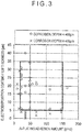
- a compound cyclic corrosion test in a JASO mode (cyclic corrosion test regulated by JASO-M609-91 (repetition of spraying salt water: spraying 5% NaCl, 35 degrees C ⁇ 2 Hr, drying: relative humidity 20%, 60 degrees C ⁇ 4 Hr, and wetting: relative humidity 90%, 50 degrees C ⁇ 2 Hr)) was used. As a test period, 200 cycles were performed. After the test was finished, the corrosion depth in a gap was measured by a microscope focal depth method.
- Fig. 3 suggests that the initial absolute amount can be controlled by the Al-plating weight per unit area and reduction in Al consumption can be controlled by the thickness of a cation electrodeposition coating film on a general surface.
- Fig. 3 indicates that the Al-plating weight per unit area is required to be 20 g/m 2 or more and the thickness of the cation electrodeposition coating film is required to be 5 ⁇ m or more. Obviously, a larger Al-plating weight per unit area and a larger thickness of the cation electrodeposition coating film are more preferable.
- an upper limit of the Al-plating weight per unit area is 150 g/m 2
- an upper limit of the thickness of the cation electrodeposition coating film is 35 ⁇ m considering inexpensiveness.
- a cation electrodeposition coating film is not formed because of a gap and an aluminized surface is exposed.
- the surface Al in this exposed part contributes to sacrificial corrosion prevention.
- the metal fitting in the invention is made of an aluminized stainless steel sheet, and requires 20 g/m 2 or more of Al-plating weight per unit area on a surface abutting on the gap. This is because satisfactory corrosion resistance cannot be obtained with a plating weight per unit area lower than the above value. On the other hand, a larger plating weight per unit area makes a life of corrosion resistance longer. However, the life can be extended to some degree by covering surfaces in other parts than a gap with a cation electrodeposition coating film, and the upper limit of the plating weight per unit area is 150 g/m 2 also considering cost.
- the "surface abutting on the gap” herein means a surface constituting the gap generated by the metal fitting coming close to or abutting on the member or the steel pipe member.
- An aluminized stainless steel sheet manufactured by a hot-dip plating method can be used.
- a Type I aluminized stainless steel sheet manufactured using an Al-8% to 10% Si bath is more preferably usable than a Type II aluminized stainless steel sheet manufactured using a pure Al bath. This is because Type I has a smaller thickness of an alloy layer existing in an interface between a plated layer and a stainless basic material and causes less peeling of the plated layer during molding than Type II.
- Such a Type I aluminized layer usually contains about 10 mass% of Si and about 1 mass% of Al-Fe-Si intermetallic compound as described in Non Patent Literature 3.
- a material for the aluminized stainless steel sheet has the same composition range as the ferritic stainless steel of the steel pipe member, and does not need to be at least a highly corrosion-resistant material having a larger alloy content than the steel pipe member.
- a cation electrodeposition coating film is formed on the metal fitting and the non-aluminized member.
- An electrodeposition coating film on the metal fitting and the non-aluminized member limits a region which an Al corrosion prevention current reaches to the gap. This suppresses a consumption rate of Al and can extend a corrosion prevention life.
- the cation electrodeposition coating film requires a film thickness of 5 ⁇ m or more. On the other hand, a too large film thickness saturates the effect, and therefore the upper limit of the cation electrodeposition coating film is preferably 35 ⁇ m. Whether a cation electrodeposition coating film is formed on a surface of a gap of the member in addition to the steel pipe member and the metal fitting depends on an opening amount of the gap.
- an attachment structure of a metal fitting made of an aluminized stainless steel sheet was examined.
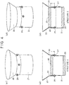
- a test piece obtained in the following manner was used as illustrated in Figs. 4(a1), 4(a2), 4(b1) and 4(b2) .
- a steel pipe 22 made of an aluminized stainless steel sheet simulating the metal fitting was welded to an outer surface and an inner surface of a ferritic stainless steel pipe 21 simulating the inlet pipe at four point spot weld portions 24 to form a gap 23.
- the ferritic stainless steel pipe 21 included components of No.
- the aluminized stainless steel pipe 22 included components of No. A3 in Table 2, and had an Al-plating weight per unit area of 49 g/cm 2 .
- the aluminized stainless steel pipe 22 was welded to the outer surface of the ferritic stainless steel pipe 21 as in structure I in Figs. 4(a1) and 4(a2) , the aluminized stainless steel pipe 22 had a shape of ⁇ 52 ⁇ 50L ⁇ 0.8t mm.
- the aluminized stainless steel pipe 22 was welded to the inner surface of the ferritic stainless steel pipe 21 as in structure II in Figs.
- the aluminized stainless steel pipe 22 had a shape of ⁇ 48 ⁇ 50L ⁇ 0.8t mm.
- the position (attachment position) of the weld portion 24 for attaching the aluminized stainless steel pipe 22 was changed within a range of 0 to 20 mm from an end of the ferritic stainless steel pipe 21.
- the test piece was subjected to cation electrodeposition coating.
- cation electrodeposition coating PN-110 manufactured by NIPPONPAINT Co., Ltd. was used as a coating material, electrification was performed at a bath temperature of 28 degrees C and a coating voltage of 170 V, and conditions were selected such that the thickness of a coating film was 30 ⁇ m in a general part (other parts than the gap 23 on the surfaces of the ferritic stainless steel pipe 21 and the aluminized stainless steel pipe 22).
- a baking condition was 170 degrees C ⁇ 20 minutes.
- the thicknesses of a coating film at five points were measured per a sample using an electromagnetic film thickness meter, and an average value thereof was used as a film thickness.
- a weld nugget was punched after electrodeposition coating, and an inside of a gap was observed. It was confirmed that no coating film was formed inside the gap.
- Test results are shown in Table 4. Any test piece did not have a hole generated by corrosion. However, in the structure II, an Al corrosion product invaded the ferritic stainless steel pipe from the consumed aluminized part. In addition, when a test piece had the structure I with an attachment position of less than 5 mm, an end surface of the steel pipe was corroded, and an Al corrosion product invaded the ferritic stainless steel pipe from a gap between the end and a silicone cap. Accordingly, it is found that when a test piece has the structure I with an attachment position of less than 5 mm from the ferritic stainless steel pipe, an Al corrosion product does not invade the ferritic stainless steel pipe.
- the metal fitting is only required to be attached to the member to such a degree that both of the metal fitting and the member are electrically conductive with each other. Furthermore, when the invention is applied to an oil inlet, the metal fitting is preferably welded to an outer surface of the inlet pipe (steel pipe member) and at a position 5 mm or more apart from an end surface of the inlet pipe. With the above arrangement an effect of preventing invasion of an Al corrosion product into the inlet pipe can be exhibited.
- a metal fitting molded made of an aluminized stainless steel sheet having an Al-plating weight per unit area of 20 g/m 2 or more and 150 g/m 2 or less is attached to a non-aluminized member made of ferritic stainless steel.
- the metal fitting is preferably attached to the non-aluminized member by welding or brazing.
- a gap is formed near the attachment part between the non-aluminized member and the metal fitting. This gap is located at a position exposed to a chloride environment. A part including the gap is referred to as a gap structure.
- the gap structure exposed to a chloride environment is formed between the non-aluminized member and the metal fitting made of an aluminized stainless steel sheet and attached to the member.
- surfaces of the metal fitting and the non-aluminized member are covered with a cation electrodeposition coating film having a thickness of 5 ⁇ m to 35 ⁇ m by cation electrodeposition coating.
- the metal fitting having Al-plating attached thereto is attached to the non-aluminized member. Therefore, the Al-plating weight per unit area of the metal fitting is 20 g/m 2 or more and 150 g/m 2 or less on a surface abutting on the gap formed near the attachment part.
- the feed oil pipe of the invention is an feed oil pipe manufactured in such a manner as described above.
- the steel pipe member herein means a pipe-shaped member such as a main pipe (inlet pipe) or a breather tube which is filled with fuel gas.
- a material described below is used for the metal fitting.
- a feature of the invention is the use of an inexpensive material with a lower content of an alloy element than SUS436L without an element for improving corrosion resistance such as Ni or Cu in addition to Mo.
- a ferritic stainless steel having the following composition is used as the material.
- the percentage (%) of the content means mass%.
- C, N Each of C and N is an element to cause intergranular corrosion at part being influenced by welding heat and deteriorates corrosion resistance and cold workability. Accordingly, the content of C or N should be limited to as low level as possible.
- the upper limit of the content of C or N is at most 0.015%, and more preferably 0.010%.
- the lower limit value is not particularly specified, but is preferably 0.0010% for C and 0.0050% for N considering refining cost.
- Cr is a basic element to assure corrosion resistance after heating, a proper content of Cr is essential, and the lower limit of the content of Cr is necessary to be 10.5%.
- the upper limit of the content is set to 18.0% in view of deterioration in workability due to the presence of Cr and for the purpose of suppressing alloy cost.
- a range of the content of Cr is preferably from 13.0% to 17.5%, and more preferably from 16.0% to 17.5%.
- the content of Cr is preferably less than 13.0%, and more preferably 12.0% or less from a viewpoint of pursuing a lower-grade material.
- Ti, Nb Ti and Nb fix C and N as a carbonitride to suppress intergranular corrosion. Accordingly, one or both of Ti and Nb are/is contained. However, an excessive content of Ti and Nb saturates the effect, and therefore the upper limit of each content of Ti and Nb is set at 0.30%. It should be noted that, when the content of at least one or both of Ti and Nb is 0.03% or more, the effect can be exhibited. As a proper content of Ti or Nb, the total content of both of the elements is five times or more and 30 times or less of the total content of C and N. The total content of Ti and Nb is preferably from 10 times to 25 times as much as the total content of C and N.
- Si is useful as a deoxidizing element in a refining step, and is contained with a lower limit of 0.01%. On the other hand, a large amount of Si deteriorates workability and thus should not be contained.
- the upper limit of Si content is limited to 0.80%.
- a preferable range of Si content is from 0.10% to 0.50%.
- Mn 0.01% or more of Mn is contained as a deoxidizing element and an element for fixing S. However, a large amount of Mn deteriorates workability and thus should not be contained.
- the upper limit of Mn content is limited to 0.80%.
- a preferable range of Mn content is from 0.10% to 0.50%.
- P is an impurity element that significantly deteriorates workability. Therefore, the content of P is preferably at a level as low as possible.
- the upper limit of an allowable content of P is 0.050%.
- the upper limit value of a preferable content of P is 0.030%.
- the lower limit value of P is not particularly specified, but is preferably 0.010% considering refining cost.
- S is an impurity element that deteriorates corrosion resistance. Therefore, the content of S is preferably at a level as low as possible.
- the upper limit of an allowable content of S is 0.010%.
- the upper limit value of a preferable content of S is 0.0050%.
- the lower limit value of S is not particularly specified, but is preferably 0.0005% considering refining cost.
- Al is useful as a deoxidizing element, and 0.010% or more of Al is contained. However, a large amount of Al should not be contained because of deteriorating workability, and the upper limit is limited to 0.100%.
- the upper limit of the content of Al is preferably 0.080%.
- alloy elements may be contained in order to adjust various characteristics of steel.
- B is an element useful for preventing secondary working embrittlement or hot workability deterioration without affecting corrosion resistance. Therefore, B is optionally contained with a lower limit of 0.0002%. However, the content of more than 0.0050% deteriorates hot workability, and therefore the upper limit of B is 0.0050%. The upper limit of the content of B is more preferably 0.0020%.
- Sn is an element useful for improving corrosion resistance with a small content thereof, and is optionally contained within such a range as not to impair inexpensiveness.
- the content of Sn is less than 0.01%, an effect of improving corrosion resistance is not exhibited.
- the content is more than 0.50%, cost is significantly increased and workability is deteriorated. Therefore, a proper range of the content is from 0.01% to 0.50%.
- the content is preferably from 0.05% to 0.30%.
- the following elements may be contained within a such range as not to impair the effect of the invention.
- Mo is an element which exhibits an effect for repairing a passive state film, is very effective for improving corrosion resistance, and particularly improves pitting corrosion resistance in combination with Cr. Therefore, when Mo is added, 0.01% or more of Mo is contained. When the content of Mo is increased, corrosion resistance is improved, but workability is deteriorated and cost is increased. Therefore, the upper limit of Mo content is 0.3%. A preferable range of Mo content is from 0.01% to 0.1%.
- Cu, Ni Cu and Ni suppress a corrosion rate when corrosion progresses, and the optional content of Cu and Ni is from 0.01% to 0.5%. However, an excessive content thereof deteriorates workability, and therefore the content of Cu and Ni is preferably from 0.01% to 0.3%.
- Sb, Zr, Co, W improves corrosion resistance, and therefore can be added, as necessary. These elements are important for suppressing a corrosion rate. However, an excessive content thereof deteriorates manufacturability and cost. Therefore, the range of Sb, Zr, Co and W content, if present, is from 0.005% to 0.5%. A more preferable range of Sb, Zr, Co and W content is from 0.05% to 0.4%.
- V improves crevice corrosion resistance, and therefore can be added, as necessary.
- an excessive content of V deteriorates workability and saturates an effect for improving corrosion resistance. Therefore, the lower limit of V content, if present, is 0.03%, and the upper limit V content is 0.5%.
- a more preferable range of V content is from 0.05% to 0.30%.
- Ga is an element to contribute to improving corrosion resistance and workability, and can be contained in an amount of 0.001% to 0.05%.
- Stainless steel having the above composition is manufactured as a steel plate by a typical method for manufacturing a stainless steel plate, including: melting and refining a steel piece in a converter or an electric furnace; and subjecting the steel piece to hot rolling pickling, cold rolling, annealing, finish pickling, and the like. Furthermore, by using this steel plate as a material, a welded pipe is manufactured by a typical method for manufacturing a stainless steel pipe, such as electric resistance welding, TIG welding, or laser welding.
- the stainless steel pipe is formed into a feed oil pipe through typical molding and assembling steps such as cold plastic working (for example, bending, expanding, or drawing), or attachment of various metal fittings by welding (for example, spot welding, projection welding, MIG welding, or TIG welding), brazing, or bolts and nuts.
- cold plastic working for example, bending, expanding, or drawing
- welding for example, spot welding, projection welding, MIG welding, or TIG welding
- brazing brazing
- Ferritic stainless steel having the composition shown in Table 2 was melted in a converter, and then was subjected to the steps of casting, hot rolling, hot rolled plate annealing, pickling, cold rolling, annealing, finishing pickling and hot-dip Al-plating to manufacture an aluminized stainless steel sheet having a thickness of 0.8 mm.
- a small plate having a size of 0.8 ⁇ 40 ⁇ 40 mm was taken from this aluminized stainless steel sheet material. The small plate simulated the metal fitting.
- a gap test piece was manufactured by overlaying the small plate on the large plate and subjecting the central part the small plate and the large plate to one point spot welding.
- the gap is defined around a part at which the large plate faces and contacts the small plate.
- the gap test piece was subjected to cation electrodeposition coating and then to a salt corrosion test.
- cation electrodeposition coating PN-110 manufactured by NIPPONPAINT Co., Ltd. was used as a coating material, electrification was performed at a bath temperature of 28 degrees C and a coating voltage of 170 V, and conditions were selected such that the thickness of a coating film was from 2 ⁇ m to 40 ⁇ m in the general part.
- a baking condition was 170 degrees C ⁇ 20 minutes.
- the thicknesses of the coating film at five points were measured per sample using an electromagnetic film thickness meter, and an average value thereof was used as a film thickness.
- the gap of the gap test piece had a very small opening amount except No. 40. Therefore, an electrodeposition coating film was not formed in the gap, a stainless steel basic material was exposed in the gap of the large plate, and an aluminized film was exposed in the gap of the small plate.
- a compound cyclic corrosion test in a JASO mode (cyclic corrosion test regulated by JASO-M609-91 (repetition of spraying salt water: spraying 5% NaCl, 35 degrees C ⁇ 2 Hr, drying: relative humidity 20%, 60 degrees C ⁇ 4 Hr, and wetting: relative humidity 90%, 50 degrees C ⁇ 2 Hr)) was used.
- a test period 200 cycles were performed.
- a gap test piece was dismantled by punching a weld nugget, and was subjected to a rust removing treatment. Thereafter, the corrosion depth in the gap of the large plate was measured by a microscope focal depth method.
- the thicknesses at ten points were measured per test piece, and a maximum value of the measurements was used as a representative value of the sample.
- a target (satisfactory) corrosion resistance was defined at a maximum corrosion depth of being less than a half the plate thickness (400 ⁇ m).
- Nos. 1 to 39 in Examples of the invention had a maximum corrosion depth of 400 ⁇ m or less, and was excellent.
- No. 40 had the same condition as No. 1, but had an opening amount of the gap of 0.2 mm, which was intentionally enlarged. The opening was formed based on the method described in paragraph [0042] of Patent Literature 4. Under the above condition, a coating film was also formed in the gap, but the gap of the large plate was covered with an electrodeposition coating. As a result, excellent corrosion resistance could be assured.
- Comparative Example No. 128 shows the results of the test where SUS436L was used as a material and the small plate was not aluminized. Both the large plate and the small plate were made of X01 (SUS436L), and were subjected to electrodeposition coating. However, crevice corrosion passed through the plate thickness, which indicates that this corrosion test was sufficiently severe.
- Nos. 1 to 39 in the invention exhibited satisfactory corrosion resistance due to the sacrificial corrosion prevention action of Al-plating and the Al consumption suppressing action of the electrodeposition coating film.
- Comparative Examples Nos. 101 to 111 each had an insufficient thickness of an electrodeposition coating film, and Comparative Examples Nos. 112 to 115 each had an insufficient Al-plating weight per unit area. Accordingly, these Comparative Examples did not exhibit satisfactory corrosion resistance.
- Comparative Examples Nos. 118 to 121, 124, and 127 each had a composition of the large plate outside the range of the invention, and therefore exhibited insufficient corrosion resistance.
- Comparative Example No. 116 had an excessive Al-plating weight per unit area resulting in a high cost
- Comparative Example No. 116 only exhibited corrosion resistance equivalent to Nos. 12 and 14 in the invention having a smaller adhesion amount. Though Comparative Example No.
- Comparative Example No. 117 had an excessive thickness of an electrodeposition coating film resulting in a high cost, Comparative Example No. 117 only exhibited corrosion resistance equivalent to No. 17 in the invention having a smaller film thickness. Comparative Examples Nos. 122, 123, 125, and 126 each had an excessive content of Ti or Nb as a material of the large plate resulting in a high cost, but only exhibited corrosion resistance equivalent to Nos. 17, 7, 11, and 1 in the invention using a material having the same content of Cr and a smaller content of Ti or Nb.
- ferritic stainless steel having the composition shown in E01 of Table 1 150 kg was melted in a vacuum furnace, was cast into a 50 kg steel ingot, and then was subjected to the steps of hot rolling, hot rolled plate annealing, pickling-cold rolling, annealing, and finishing pickling to manufacture a steel plate having a thickness of 0.8 mm.
- a steel pipe having a size of ⁇ 50 ⁇ 50 ⁇ t0.8 mm was manufactured by seam welding to obtain the ferritic stainless steel pipe 21.
- the ferritic stainless steel pipe 21 simulated an inlet pipe.
- Ferritic stainless steel having the composition shown in A3 of Table 2 was melted in a converter, and then was subjected to the steps of casting, hot rolling, hot rolled plate annealing, pickling, cold rolling, annealing, finishing pickling and hot-dip Al-plating to manufacture an aluminized stainless steel sheet having a thickness of 0.8 mm.
- the Al-plating weight per unit area was 49 g/cm 2 .
- parts having sizes of ⁇ 48 ⁇ 50 ⁇ t0.8 mm and ⁇ 52 ⁇ 50 ⁇ t0.8 mm were manufactured by punching and press molding to obtain the aluminized stainless steel pipes 22.
- the aluminized stainless steel pipe 22 simulated a metal fitting.
- the aluminized stainless steel pipe 22 was welded to an outside or an inside of the ferritic stainless steel pipe 21 at an attachment position 27 along an outer periphery 0 mm to 20 mm apart from an end 26 of the ferritic stainless steel pipe 21 by four point spot welding (weld portion 24) to manufacture a test piece.
- a gap 23 is defined at a part at which the ferritic stainless steel pipe 21 faces the aluminized stainless steel pipe 22 to be in contact therewith.
- the test piece was subjected to cation electrodeposition coating.
- cation electrodeposition coating PN-110 manufactured by NIPPONPAINT Co., Ltd. was used as a coating material, electrification was performed at a bath temperature of 28 degrees C and a coating voltage of 170 V, and conditions were selected such that the thickness of a coating film was from 30 ⁇ m in the general part.
- a baking condition was 170 degrees C ⁇ 20 minutes.
- the thicknesses of a coating film at five points were measured per a sample using an electromagnetic film thickness meter, and an average value thereof was used as a film thickness.
- the gap 23 of the gap test piece had a very small opening amount. Therefore, an electrodeposition coating film was not formed in the gap 23, a stainless steel basic material was exposed in the gap of the ferritic stainless steel pipe 21, and an aluminized film was exposed in the gap of the aluminized stainless steel pipe 22.
- Test standards and test results are shown in Table 4. None of the test pieces did have a hole in the ferritic stainless steel pipe. In other words, all of Examples of the invention and Reference Examples shown in Table 4 exhibit the effect of the invention.
- Each of Nos. a to d in Examples of the invention had structure I with the attachment position 27 of 5 mm or more from the end 26 of the ferritic stainless steel pipe. In any one of Nos. a to d, invasion of an Al corrosion product into the ferritic stainless steel pipe could not be observed.
- Each of Nos. 1a and 1b had the structure I with the attachment position 27 of less than 5 mm from the end 26 of the ferritic stainless steel pipe. An end surface of the steel pipe was corroded due to a liquid reservoir, and an Al corrosion product invaded the ferritic stainless steel pipe from a gap between the end and the silicone cap. Comparative Examples 1c to 1g had the structure II. An Al corrosion product invaded the ferritic stainless steel pipe from the aluminized part consumed.
Landscapes
- Chemical & Material Sciences (AREA)
- Engineering & Computer Science (AREA)
- Mechanical Engineering (AREA)
- Materials Engineering (AREA)
- Metallurgy (AREA)
- Organic Chemistry (AREA)
- General Engineering & Computer Science (AREA)
- Chemical Kinetics & Catalysis (AREA)
- Electrochemistry (AREA)
- Combustion & Propulsion (AREA)
- Sustainable Energy (AREA)
- Transportation (AREA)
- Sustainable Development (AREA)
- Life Sciences & Earth Sciences (AREA)
- Physics & Mathematics (AREA)
- Oil, Petroleum & Natural Gas (AREA)
- Thermal Sciences (AREA)
- Cooling, Air Intake And Gas Exhaust, And Fuel Tank Arrangements In Propulsion Units (AREA)
- Prevention Of Electric Corrosion (AREA)
- Fuel-Injection Apparatus (AREA)
- Laminated Bodies (AREA)
Claims (5)
- Eine Zuführölleitung umfassend:ein nicht-aluminiertes Stahlrohrelement;einen Metallbeschlag aus einem aluminierten rostfreien Stahlblech, wobei der Metallbeschlag an dem Stahlrohrelement befestigt ist; undeine Spaltstruktur, definiert zwischen einer Position an einer äußeren Umfangsfläche des nicht-aluminierten Stahlrohrelements, die nicht in Kontakt mit einem Brennstoff steht, und dem Metallbeschlag, wobei die Spaltstruktur einer Chlorid-haltigen Umgebung ausgesetzt ist,worin das nicht-aluminierte Stahlrohrelement aus einem ferritischen rostfreien Stahl hergestellt ist, bestehend aus, in Massen-%, höchstens 0,015 % C, höchstens 0,015 % N, 10,5 % bis 18,0 % Cr, 0,01 % bis 0,80 % Si, 0,01 % bis 0,80 % Mn, höchstens 0,050 % P, höchstens 0,010 % S, 0,010 % bis 0,100 % Al, höchstens 0,30 % Ti und höchstens 0,30 % Nb, wobei eines oder beide von Ti und Nb mindestens 0,03 % betragen, optional einem oder beiden von 0,0002 % bis 0,0050 % B und 0,01 % bis 0,50 % Sn, und außerdem optional einem oder mehreren von 0,01 % bis 0,3 % Mo, 0,01 % bis 0,5 % Cu, 0,01 % bis 0,5 % Ni, 0,005 % bis 0,5 % Sb, 0,005 % bis 0,5 % Zr, 0,005 % bis 0,5 % Co, 0,005 % bis 0,5 % W, 0,03 % bis 0,5 % V, und 0,001 % bis 0,05 % Ga, und einem Rest in Form von Fe und unvermeidlichen Verunreinigungen, undworin der rostfreie Stahl des Metallbeschlags den gleichen Zusammensetzungsbereich wie der ferritische rostfreie Stahl des Stahlrohrelements hat,das aluminierte rostfreie Stahlblech für den Metallbeschlag ein Al-Beschichtungsgewicht pro Flächeneinheit von 20 g/m2 oder mehr und 150 g/m2 oder weniger aufweist, undder Metallbeschlag und das nicht-aluminierte Element mit einem Kationen-Elektroabscheidungs-Beschichtungsfilm mit einer Dicke von 5 µm bis 35 µm beschichtet sind.
- Die Zuführölleitung gemäß Anspruch 1, worin der Metallbeschlag durch Schweißen oder Löten an einer Stelle der äußeren Umfangsoberfläche des nicht-aluminierten Stahlrohrelements befestigt ist, die nicht mit einem Brennstoff in Berührung kommt.
- Die Zuführölleitung gemäß Anspruch 1 oder 2, worin das nicht-aluminierte Stahlrohrelement aus ferritischem rostfreiem Stahl hergestellt ist, umfassend, in Massen-%, eines oder beide von 0,0002 % bis 0,0050 % B und 0,01 % bis 0,50 % Sn.
- Die Zuführölleitung gemäß einem der Ansprüche 1 bis 3, worin das nicht-aluminierte Stahlrohrelement aus ferrischem rostfreiem Stahl hergestellt ist, umfassend, in Massen-%, eines oder mehrere von 0,01 % bis 0,3 % Mo, 0,01 % bis 0,5 % Cu, 0,01 % bis 0,5 % Ni, 0,005 % bis 0,5 % Sb, 0,005 % bis 0,5 % Zr, 0,005 % bis 0,5 % Co, 0,005 % bis 0,5 % W, 0,03 % bis 0,5 % V, und 0,001 % bis 0,05 % Ga.
- Die Zuführölleitung gemäß einem der Ansprüche 1 bis 4, worin eine Öl-Einlassstruktur definiert ist, in der das Stahlrohrelement ein Einlassrohr ist, der Metallbeschlag ein Kegelstumpfelement ist, das an einem äußeren Umfang des Stahlrohrelements mit einem Boden mit kleinem Durchmesser des Kegelstumpfes an einer Position 5 mm oder mehr von einem Ende des Einlassrohrs entfernt befestigt ist.
Applications Claiming Priority (2)
| Application Number | Priority Date | Filing Date | Title |
|---|---|---|---|
| JP2013074839 | 2013-09-13 | ||
| PCT/JP2014/074238 WO2015037707A1 (ja) | 2013-09-13 | 2014-09-12 | 廉価で塩害耐食性に優れた自動車用部材および給油管 |
Publications (3)
| Publication Number | Publication Date |
|---|---|
| EP3045338A1 EP3045338A1 (de) | 2016-07-20 |
| EP3045338A4 EP3045338A4 (de) | 2017-04-19 |
| EP3045338B1 true EP3045338B1 (de) | 2019-02-20 |
Family
ID=52665805
Family Applications (1)
| Application Number | Title | Priority Date | Filing Date |
|---|---|---|---|
| EP14844177.7A Active EP3045338B1 (de) | 2013-09-13 | 2014-09-12 | Ölzuleitungsrohr mit hervorragender beständigkeit gegen salzkorrosion |
Country Status (8)
| Country | Link |
|---|---|
| US (1) | US9963767B2 (de) |
| EP (1) | EP3045338B1 (de) |
| JP (1) | JP6363084B2 (de) |
| KR (1) | KR101954628B1 (de) |
| CN (1) | CN105764733B (de) |
| CA (1) | CA2924212C (de) |
| MX (1) | MX381678B (de) |
| WO (1) | WO2015037707A1 (de) |
Families Citing this family (16)
| Publication number | Priority date | Publication date | Assignee | Title |
|---|---|---|---|---|
| MX389535B (es) * | 2015-02-10 | 2025-03-20 | Nippon Steel Stainless Steel Corp | Componente económico para automóvil y tubo de alimentación de aceite que tienen excelente resistencia a la corrosión por sal. |
| JP6541992B2 (ja) * | 2015-03-12 | 2019-07-10 | 日鉄ステンレス株式会社 | 塗装かつ犠牲防食効果を利用した耐穴あき性に優れた自動車用部材および自動車用給油管 |
| JP6598478B2 (ja) * | 2015-03-12 | 2019-10-30 | 日鉄ステンレス株式会社 | 塩害耐食性に優れかつ外観劣化を抑制した自動車用給油管 |
| CN104878301B (zh) * | 2015-05-15 | 2017-05-03 | 河冶科技股份有限公司 | 喷射成形高速钢 |
| JP6782621B2 (ja) * | 2015-12-09 | 2020-11-11 | 日鉄ステンレス株式会社 | 自動車用部材 |
| KR102047401B1 (ko) * | 2015-12-21 | 2019-11-25 | 주식회사 포스코 | 내공식성 및 내응축수 부식성이 개선된 자동차 배기계용 페라이트계 스테인리스강 및 이의 제조 방법 |
| JPWO2017222031A1 (ja) * | 2016-06-24 | 2019-04-25 | ユニプレス株式会社 | 燃料タンクに接続された管状部材の車体への取付け構造及び配管構造体 |
| WO2017221450A1 (ja) * | 2016-06-24 | 2017-12-28 | ユニプレス株式会社 | フィラーチューブ構造 |
| JP6665936B2 (ja) * | 2016-12-21 | 2020-03-13 | Jfeスチール株式会社 | フェライト系ステンレス鋼 |
| FR3065488B1 (fr) * | 2017-04-20 | 2019-06-28 | Faurecia Systemes D'echappement | Element de ligne d'echappement et procede de fabrication d'un tel element |
| DE102017115250A1 (de) * | 2017-07-07 | 2019-01-10 | Endress+Hauser SE+Co. KG | Korrosionsschutz-Element für ein Feldgerät |
| WO2019097729A1 (ja) * | 2017-11-20 | 2019-05-23 | 日本製鉄株式会社 | 焼入れ用Alめっき溶接管、並びにAlめっき中空部材及びその製造方法 |
| CN108315648B (zh) * | 2018-02-13 | 2020-04-14 | 济南大学 | 一种载有scr处理装置的汽车排气系统后级消声器用铁素体不锈钢及制备方法 |
| WO2019191233A1 (en) * | 2018-03-28 | 2019-10-03 | Fluid Routing Solutions, LLC | Two-piece fuel filler tube assembly bracket |
| JP7186601B2 (ja) * | 2018-12-21 | 2022-12-09 | 日鉄ステンレス株式会社 | 高圧水素ガス用機器の金属材料として用いるCr系ステンレス鋼 |
| JP6566376B1 (ja) * | 2019-02-22 | 2019-08-28 | 三桜工業株式会社 | 管継手及び管継手付きチューブ並びに管継手の製造方法 |
Family Cites Families (12)
| Publication number | Priority date | Publication date | Assignee | Title |
|---|---|---|---|---|
| JP4354140B2 (ja) * | 2000-12-04 | 2009-10-28 | フタバ産業株式会社 | フューエルインレットの製造方法 |
| US6615489B2 (en) * | 2000-12-04 | 2003-09-09 | Futaba Industrial Co., Ltd. | Method of manufacturing a fuel inlet |
| JP4014907B2 (ja) * | 2002-03-27 | 2007-11-28 | 日新製鋼株式会社 | 耐食性に優れたステンレス鋼製の自動車用燃料タンクおよび給油管 |
| JP2004021003A (ja) | 2002-06-18 | 2004-01-22 | Sony Corp | アライメント調整装置およびアライメント調整方法 |
| JP4340478B2 (ja) * | 2003-06-09 | 2009-10-07 | ユニプレス株式会社 | フィラーパイプ |
| JP2005206064A (ja) | 2004-01-23 | 2005-08-04 | Asteer Co Ltd | ステンレス鋼製の燃料給油管 |
| JP2006144040A (ja) * | 2004-11-16 | 2006-06-08 | Nippon Steel & Sumikin Stainless Steel Corp | 生産性に優れた高耐食性燃料系部品の製造方法 |
| JP4652081B2 (ja) | 2005-02-25 | 2011-03-16 | アイシン化工株式会社 | フューエルインレットの塗装方法 |
| JP2007216935A (ja) * | 2006-02-20 | 2007-08-30 | Asteer Co Ltd | 燃料給油管 |
| JP2012012005A (ja) * | 2010-06-03 | 2012-01-19 | Nippon Steel & Sumikin Stainless Steel Corp | 給油管およびその製造方法 |
| JP5623240B2 (ja) | 2010-10-29 | 2014-11-12 | 株式会社アステア | 燃料給油管 |
| JP6084769B2 (ja) * | 2010-12-21 | 2017-02-22 | 新日鐵住金ステンレス株式会社 | 給油管およびその製造方法 |
-
2014
- 2014-09-12 EP EP14844177.7A patent/EP3045338B1/de active Active
- 2014-09-12 MX MX2016003099A patent/MX381678B/es unknown
- 2014-09-12 KR KR1020167008353A patent/KR101954628B1/ko active Active
- 2014-09-12 US US15/021,078 patent/US9963767B2/en active Active
- 2014-09-12 CN CN201480050269.9A patent/CN105764733B/zh active Active
- 2014-09-12 JP JP2015536643A patent/JP6363084B2/ja active Active
- 2014-09-12 WO PCT/JP2014/074238 patent/WO2015037707A1/ja not_active Ceased
- 2014-09-12 CA CA2924212A patent/CA2924212C/en active Active
Non-Patent Citations (1)
| Title |
|---|
| None * |
Also Published As
| Publication number | Publication date |
|---|---|
| KR20160055171A (ko) | 2016-05-17 |
| CN105764733B (zh) | 2018-09-07 |
| KR101954628B1 (ko) | 2019-03-06 |
| JP6363084B2 (ja) | 2018-07-25 |
| CA2924212A1 (en) | 2015-03-19 |
| CN105764733A (zh) | 2016-07-13 |
| US20160230261A1 (en) | 2016-08-11 |
| MX2016003099A (es) | 2016-09-08 |
| MX381678B (es) | 2025-03-13 |
| WO2015037707A1 (ja) | 2015-03-19 |
| EP3045338A1 (de) | 2016-07-20 |
| CA2924212C (en) | 2018-11-06 |
| EP3045338A4 (de) | 2017-04-19 |
| US9963767B2 (en) | 2018-05-08 |
| JPWO2015037707A1 (ja) | 2017-03-02 |
Similar Documents
| Publication | Publication Date | Title |
|---|---|---|
| EP3045338B1 (de) | Ölzuleitungsrohr mit hervorragender beständigkeit gegen salzkorrosion | |
| CA2975977C (en) | Inexpensive automobile component and oil feed pipe having excellent salt corrosion resistance | |
| KR101436711B1 (ko) | 급유관 및 그 제조 방법 | |
| JP6084769B2 (ja) | 給油管およびその製造方法 | |
| JP6782621B2 (ja) | 自動車用部材 | |
| JP6598478B2 (ja) | 塩害耐食性に優れかつ外観劣化を抑制した自動車用給油管 | |
| JPWO2007004671A1 (ja) | 良好な耐食性を有する溶融Sn−Zn系めっき鋼板 | |
| JP6541992B2 (ja) | 塗装かつ犠牲防食効果を利用した耐穴あき性に優れた自動車用部材および自動車用給油管 | |
| JP5428571B2 (ja) | 車両用の燃料タンク | |
| JP2014177661A (ja) | Sn−Znめっき鋼板の耐食性判定方法および耐食性判定を満足するSn−Znめっき鋼板 | |
| JP5664408B2 (ja) | 溶融Sn−Znめっき鋼板 | |
| JP2003268520A (ja) | 耐食性の優れた溶融Sn−Znめっき鋼材の製造方法 | |
| JP2003293110A (ja) | 耐食性の優れた溶融Sn−Znめっき鋼材の製造方法 | |
| JP2010173525A (ja) | 自動二輪車燃料タンク用めっき鋼板および燃料タンク | |
| MX2007015836A (es) | Hoja de acero recubierta con un sistema de sn - zn de inmersion en caliente que tiene excelente resistencia a la corrosion. |
Legal Events
| Date | Code | Title | Description |
|---|---|---|---|
| PUAI | Public reference made under article 153(3) epc to a published international application that has entered the european phase |
Free format text: ORIGINAL CODE: 0009012 |
|
| 17P | Request for examination filed |
Effective date: 20160407 |
|
| AK | Designated contracting states |
Kind code of ref document: A1 Designated state(s): AL AT BE BG CH CY CZ DE DK EE ES FI FR GB GR HR HU IE IS IT LI LT LU LV MC MK MT NL NO PL PT RO RS SE SI SK SM TR |
|
| AX | Request for extension of the european patent |
Extension state: BA ME |
|
| DAX | Request for extension of the european patent (deleted) | ||
| A4 | Supplementary search report drawn up and despatched |
Effective date: 20170321 |
|
| STAA | Information on the status of an ep patent application or granted ep patent |
Free format text: STATUS: EXAMINATION IS IN PROGRESS |
|
| 17Q | First examination report despatched |
Effective date: 20180124 |
|
| GRAP | Despatch of communication of intention to grant a patent |
Free format text: ORIGINAL CODE: EPIDOSNIGR1 |
|
| STAA | Information on the status of an ep patent application or granted ep patent |
Free format text: STATUS: GRANT OF PATENT IS INTENDED |
|
| RIC1 | Information provided on ipc code assigned before grant |
Ipc: C22C 38/24 20060101ALI20180817BHEP Ipc: C23C 2/12 20060101ALI20180817BHEP Ipc: C23F 13/00 20060101ALI20180817BHEP Ipc: C23C 28/00 20060101ALI20180817BHEP Ipc: F02M 37/00 20060101ALI20180817BHEP Ipc: F16L 58/00 20060101ALI20180817BHEP Ipc: C22C 38/32 20060101ALI20180817BHEP Ipc: B60K 15/04 20060101AFI20180817BHEP Ipc: F16L 3/02 20060101ALI20180817BHEP Ipc: C25D 9/00 20060101ALI20180817BHEP Ipc: F16L 58/08 20060101ALI20180817BHEP Ipc: C22C 38/30 20060101ALI20180817BHEP Ipc: C22C 38/26 20060101ALI20180817BHEP Ipc: C23F 13/16 20060101ALI20180817BHEP Ipc: C22C 38/22 20060101ALI20180817BHEP Ipc: C22C 38/02 20060101ALI20180817BHEP Ipc: C25D 13/12 20060101ALI20180817BHEP Ipc: C22C 38/06 20060101ALI20180817BHEP Ipc: C22C 38/04 20060101ALI20180817BHEP Ipc: C22C 38/28 20060101ALI20180817BHEP |
|
| INTG | Intention to grant announced |
Effective date: 20180905 |
|
| GRAS | Grant fee paid |
Free format text: ORIGINAL CODE: EPIDOSNIGR3 |
|
| GRAA | (expected) grant |
Free format text: ORIGINAL CODE: 0009210 |
|
| STAA | Information on the status of an ep patent application or granted ep patent |
Free format text: STATUS: THE PATENT HAS BEEN GRANTED |
|
| RIN1 | Information on inventor provided before grant (corrected) |
Inventor name: SAKAMOTO SHUNJI Inventor name: TANOUE TOSHIO Inventor name: TERAOKA SHINICHI Inventor name: URASHIMA HIROSHI |
|
| AK | Designated contracting states |
Kind code of ref document: B1 Designated state(s): AL AT BE BG CH CY CZ DE DK EE ES FI FR GB GR HR HU IE IS IT LI LT LU LV MC MK MT NL NO PL PT RO RS SE SI SK SM TR |
|
| REG | Reference to a national code |
Ref country code: GB Ref legal event code: FG4D |
|
| REG | Reference to a national code |
Ref country code: CH Ref legal event code: EP |
|
| REG | Reference to a national code |
Ref country code: DE Ref legal event code: R096 Ref document number: 602014041492 Country of ref document: DE |
|
| REG | Reference to a national code |
Ref country code: AT Ref legal event code: REF Ref document number: 1097713 Country of ref document: AT Kind code of ref document: T Effective date: 20190315 |
|
| REG | Reference to a national code |
Ref country code: IE Ref legal event code: FG4D |
|
| REG | Reference to a national code |
Ref country code: NL Ref legal event code: MP Effective date: 20190220 |
|
| REG | Reference to a national code |
Ref country code: LT Ref legal event code: MG4D |
|
| PG25 | Lapsed in a contracting state [announced via postgrant information from national office to epo] |
Ref country code: FI Free format text: LAPSE BECAUSE OF FAILURE TO SUBMIT A TRANSLATION OF THE DESCRIPTION OR TO PAY THE FEE WITHIN THE PRESCRIBED TIME-LIMIT Effective date: 20190220 Ref country code: NO Free format text: LAPSE BECAUSE OF FAILURE TO SUBMIT A TRANSLATION OF THE DESCRIPTION OR TO PAY THE FEE WITHIN THE PRESCRIBED TIME-LIMIT Effective date: 20190520 Ref country code: PT Free format text: LAPSE BECAUSE OF FAILURE TO SUBMIT A TRANSLATION OF THE DESCRIPTION OR TO PAY THE FEE WITHIN THE PRESCRIBED TIME-LIMIT Effective date: 20190620 Ref country code: SE Free format text: LAPSE BECAUSE OF FAILURE TO SUBMIT A TRANSLATION OF THE DESCRIPTION OR TO PAY THE FEE WITHIN THE PRESCRIBED TIME-LIMIT Effective date: 20190220 Ref country code: LT Free format text: LAPSE BECAUSE OF FAILURE TO SUBMIT A TRANSLATION OF THE DESCRIPTION OR TO PAY THE FEE WITHIN THE PRESCRIBED TIME-LIMIT Effective date: 20190220 Ref country code: NL Free format text: LAPSE BECAUSE OF FAILURE TO SUBMIT A TRANSLATION OF THE DESCRIPTION OR TO PAY THE FEE WITHIN THE PRESCRIBED TIME-LIMIT Effective date: 20190220 |
|
| PG25 | Lapsed in a contracting state [announced via postgrant information from national office to epo] |
Ref country code: LV Free format text: LAPSE BECAUSE OF FAILURE TO SUBMIT A TRANSLATION OF THE DESCRIPTION OR TO PAY THE FEE WITHIN THE PRESCRIBED TIME-LIMIT Effective date: 20190220 Ref country code: RS Free format text: LAPSE BECAUSE OF FAILURE TO SUBMIT A TRANSLATION OF THE DESCRIPTION OR TO PAY THE FEE WITHIN THE PRESCRIBED TIME-LIMIT Effective date: 20190220 Ref country code: HR Free format text: LAPSE BECAUSE OF FAILURE TO SUBMIT A TRANSLATION OF THE DESCRIPTION OR TO PAY THE FEE WITHIN THE PRESCRIBED TIME-LIMIT Effective date: 20190220 Ref country code: IS Free format text: LAPSE BECAUSE OF FAILURE TO SUBMIT A TRANSLATION OF THE DESCRIPTION OR TO PAY THE FEE WITHIN THE PRESCRIBED TIME-LIMIT Effective date: 20190620 Ref country code: BG Free format text: LAPSE BECAUSE OF FAILURE TO SUBMIT A TRANSLATION OF THE DESCRIPTION OR TO PAY THE FEE WITHIN THE PRESCRIBED TIME-LIMIT Effective date: 20190520 Ref country code: GR Free format text: LAPSE BECAUSE OF FAILURE TO SUBMIT A TRANSLATION OF THE DESCRIPTION OR TO PAY THE FEE WITHIN THE PRESCRIBED TIME-LIMIT Effective date: 20190521 |
|
| REG | Reference to a national code |
Ref country code: AT Ref legal event code: MK05 Ref document number: 1097713 Country of ref document: AT Kind code of ref document: T Effective date: 20190220 |
|
| PG25 | Lapsed in a contracting state [announced via postgrant information from national office to epo] |
Ref country code: EE Free format text: LAPSE BECAUSE OF FAILURE TO SUBMIT A TRANSLATION OF THE DESCRIPTION OR TO PAY THE FEE WITHIN THE PRESCRIBED TIME-LIMIT Effective date: 20190220 Ref country code: IT Free format text: LAPSE BECAUSE OF FAILURE TO SUBMIT A TRANSLATION OF THE DESCRIPTION OR TO PAY THE FEE WITHIN THE PRESCRIBED TIME-LIMIT Effective date: 20190220 Ref country code: DK Free format text: LAPSE BECAUSE OF FAILURE TO SUBMIT A TRANSLATION OF THE DESCRIPTION OR TO PAY THE FEE WITHIN THE PRESCRIBED TIME-LIMIT Effective date: 20190220 Ref country code: CZ Free format text: LAPSE BECAUSE OF FAILURE TO SUBMIT A TRANSLATION OF THE DESCRIPTION OR TO PAY THE FEE WITHIN THE PRESCRIBED TIME-LIMIT Effective date: 20190220 Ref country code: RO Free format text: LAPSE BECAUSE OF FAILURE TO SUBMIT A TRANSLATION OF THE DESCRIPTION OR TO PAY THE FEE WITHIN THE PRESCRIBED TIME-LIMIT Effective date: 20190220 Ref country code: SK Free format text: LAPSE BECAUSE OF FAILURE TO SUBMIT A TRANSLATION OF THE DESCRIPTION OR TO PAY THE FEE WITHIN THE PRESCRIBED TIME-LIMIT Effective date: 20190220 Ref country code: AL Free format text: LAPSE BECAUSE OF FAILURE TO SUBMIT A TRANSLATION OF THE DESCRIPTION OR TO PAY THE FEE WITHIN THE PRESCRIBED TIME-LIMIT Effective date: 20190220 Ref country code: ES Free format text: LAPSE BECAUSE OF FAILURE TO SUBMIT A TRANSLATION OF THE DESCRIPTION OR TO PAY THE FEE WITHIN THE PRESCRIBED TIME-LIMIT Effective date: 20190220 |
|
| REG | Reference to a national code |
Ref country code: DE Ref legal event code: R097 Ref document number: 602014041492 Country of ref document: DE |
|
| PG25 | Lapsed in a contracting state [announced via postgrant information from national office to epo] |
Ref country code: SM Free format text: LAPSE BECAUSE OF FAILURE TO SUBMIT A TRANSLATION OF THE DESCRIPTION OR TO PAY THE FEE WITHIN THE PRESCRIBED TIME-LIMIT Effective date: 20190220 Ref country code: PL Free format text: LAPSE BECAUSE OF FAILURE TO SUBMIT A TRANSLATION OF THE DESCRIPTION OR TO PAY THE FEE WITHIN THE PRESCRIBED TIME-LIMIT Effective date: 20190220 |
|
| PLBE | No opposition filed within time limit |
Free format text: ORIGINAL CODE: 0009261 |
|
| STAA | Information on the status of an ep patent application or granted ep patent |
Free format text: STATUS: NO OPPOSITION FILED WITHIN TIME LIMIT |
|
| PG25 | Lapsed in a contracting state [announced via postgrant information from national office to epo] |
Ref country code: AT Free format text: LAPSE BECAUSE OF FAILURE TO SUBMIT A TRANSLATION OF THE DESCRIPTION OR TO PAY THE FEE WITHIN THE PRESCRIBED TIME-LIMIT Effective date: 20190220 |
|
| 26N | No opposition filed |
Effective date: 20191121 |
|
| PG25 | Lapsed in a contracting state [announced via postgrant information from national office to epo] |
Ref country code: SI Free format text: LAPSE BECAUSE OF FAILURE TO SUBMIT A TRANSLATION OF THE DESCRIPTION OR TO PAY THE FEE WITHIN THE PRESCRIBED TIME-LIMIT Effective date: 20190220 |
|
| PG25 | Lapsed in a contracting state [announced via postgrant information from national office to epo] |
Ref country code: TR Free format text: LAPSE BECAUSE OF FAILURE TO SUBMIT A TRANSLATION OF THE DESCRIPTION OR TO PAY THE FEE WITHIN THE PRESCRIBED TIME-LIMIT Effective date: 20190220 |
|
| PG25 | Lapsed in a contracting state [announced via postgrant information from national office to epo] |
Ref country code: MC Free format text: LAPSE BECAUSE OF FAILURE TO SUBMIT A TRANSLATION OF THE DESCRIPTION OR TO PAY THE FEE WITHIN THE PRESCRIBED TIME-LIMIT Effective date: 20190220 |
|
| REG | Reference to a national code |
Ref country code: CH Ref legal event code: PL |
|
| PG25 | Lapsed in a contracting state [announced via postgrant information from national office to epo] |
Ref country code: IE Free format text: LAPSE BECAUSE OF NON-PAYMENT OF DUE FEES Effective date: 20190912 Ref country code: LU Free format text: LAPSE BECAUSE OF NON-PAYMENT OF DUE FEES Effective date: 20190912 Ref country code: CH Free format text: LAPSE BECAUSE OF NON-PAYMENT OF DUE FEES Effective date: 20190930 Ref country code: LI Free format text: LAPSE BECAUSE OF NON-PAYMENT OF DUE FEES Effective date: 20190930 |
|
| REG | Reference to a national code |
Ref country code: BE Ref legal event code: MM Effective date: 20190930 |
|
| PG25 | Lapsed in a contracting state [announced via postgrant information from national office to epo] |
Ref country code: BE Free format text: LAPSE BECAUSE OF NON-PAYMENT OF DUE FEES Effective date: 20190930 |
|
| PG25 | Lapsed in a contracting state [announced via postgrant information from national office to epo] |
Ref country code: CY Free format text: LAPSE BECAUSE OF FAILURE TO SUBMIT A TRANSLATION OF THE DESCRIPTION OR TO PAY THE FEE WITHIN THE PRESCRIBED TIME-LIMIT Effective date: 20190220 |
|
| PG25 | Lapsed in a contracting state [announced via postgrant information from national office to epo] |
Ref country code: MT Free format text: LAPSE BECAUSE OF FAILURE TO SUBMIT A TRANSLATION OF THE DESCRIPTION OR TO PAY THE FEE WITHIN THE PRESCRIBED TIME-LIMIT Effective date: 20190220 Ref country code: HU Free format text: LAPSE BECAUSE OF FAILURE TO SUBMIT A TRANSLATION OF THE DESCRIPTION OR TO PAY THE FEE WITHIN THE PRESCRIBED TIME-LIMIT; INVALID AB INITIO Effective date: 20140912 |
|
| REG | Reference to a national code |
Ref country code: DE Ref legal event code: R081 Ref document number: 602014041492 Country of ref document: DE Owner name: NIPPON STEEL STAINLESS STEEL CORPORATION, JP Free format text: FORMER OWNER: NIPPON STEEL & SUMIKIN STAINLESS STEEL CORPORATION, TOKYO, JP |
|
| PG25 | Lapsed in a contracting state [announced via postgrant information from national office to epo] |
Ref country code: MK Free format text: LAPSE BECAUSE OF FAILURE TO SUBMIT A TRANSLATION OF THE DESCRIPTION OR TO PAY THE FEE WITHIN THE PRESCRIBED TIME-LIMIT Effective date: 20190220 |
|
| PGFP | Annual fee paid to national office [announced via postgrant information from national office to epo] |
Ref country code: DE Payment date: 20250924 Year of fee payment: 12 |
|
| PGFP | Annual fee paid to national office [announced via postgrant information from national office to epo] |
Ref country code: GB Payment date: 20250925 Year of fee payment: 12 |
|
| PGFP | Annual fee paid to national office [announced via postgrant information from national office to epo] |
Ref country code: FR Payment date: 20250925 Year of fee payment: 12 |