EP3045276A1 - Blade and rotary blade mounting with hollow rotor for food slicer - Google Patents
Blade and rotary blade mounting with hollow rotor for food slicer Download PDFInfo
- Publication number
- EP3045276A1 EP3045276A1 EP16020013.5A EP16020013A EP3045276A1 EP 3045276 A1 EP3045276 A1 EP 3045276A1 EP 16020013 A EP16020013 A EP 16020013A EP 3045276 A1 EP3045276 A1 EP 3045276A1
- Authority
- EP
- European Patent Office
- Prior art keywords
- knife
- cutting edge
- rotor
- blade
- axis
- Prior art date
- Legal status (The legal status is an assumption and is not a legal conclusion. Google has not performed a legal analysis and makes no representation as to the accuracy of the status listed.)
- Withdrawn
Links
Images

Classifications
-
- B—PERFORMING OPERATIONS; TRANSPORTING
- B26—HAND CUTTING TOOLS; CUTTING; SEVERING
- B26D—CUTTING; DETAILS COMMON TO MACHINES FOR PERFORATING, PUNCHING, CUTTING-OUT, STAMPING-OUT OR SEVERING
- B26D1/00—Cutting through work characterised by the nature or movement of the cutting member or particular materials not otherwise provided for; Apparatus or machines therefor; Cutting members therefor
- B26D1/01—Cutting through work characterised by the nature or movement of the cutting member or particular materials not otherwise provided for; Apparatus or machines therefor; Cutting members therefor involving a cutting member which does not travel with the work
- B26D1/12—Cutting through work characterised by the nature or movement of the cutting member or particular materials not otherwise provided for; Apparatus or machines therefor; Cutting members therefor involving a cutting member which does not travel with the work having a cutting member moving about an axis
- B26D1/25—Cutting through work characterised by the nature or movement of the cutting member or particular materials not otherwise provided for; Apparatus or machines therefor; Cutting members therefor involving a cutting member which does not travel with the work having a cutting member moving about an axis with a non-circular cutting member
- B26D1/43—Cutting through work characterised by the nature or movement of the cutting member or particular materials not otherwise provided for; Apparatus or machines therefor; Cutting members therefor involving a cutting member which does not travel with the work having a cutting member moving about an axis with a non-circular cutting member moving about another axis, e.g. mounted on the surface of a cone or curved body
-
- B—PERFORMING OPERATIONS; TRANSPORTING
- B26—HAND CUTTING TOOLS; CUTTING; SEVERING
- B26D—CUTTING; DETAILS COMMON TO MACHINES FOR PERFORATING, PUNCHING, CUTTING-OUT, STAMPING-OUT OR SEVERING
- B26D1/00—Cutting through work characterised by the nature or movement of the cutting member or particular materials not otherwise provided for; Apparatus or machines therefor; Cutting members therefor
-
- B—PERFORMING OPERATIONS; TRANSPORTING
- B26—HAND CUTTING TOOLS; CUTTING; SEVERING
- B26D—CUTTING; DETAILS COMMON TO MACHINES FOR PERFORATING, PUNCHING, CUTTING-OUT, STAMPING-OUT OR SEVERING
- B26D3/00—Cutting work characterised by the nature of the cut made; Apparatus therefor
- B26D3/28—Splitting layers from work; Mutually separating layers by cutting
- B26D3/283—Household devices therefor
-
- B—PERFORMING OPERATIONS; TRANSPORTING
- B26—HAND CUTTING TOOLS; CUTTING; SEVERING
- B26D—CUTTING; DETAILS COMMON TO MACHINES FOR PERFORATING, PUNCHING, CUTTING-OUT, STAMPING-OUT OR SEVERING
- B26D7/00—Details of apparatus for cutting, cutting-out, stamping-out, punching, perforating, or severing by means other than cutting
- B26D7/26—Means for mounting or adjusting the cutting member; Means for adjusting the stroke of the cutting member
- B26D7/2614—Means for mounting the cutting member
-
- B—PERFORMING OPERATIONS; TRANSPORTING
- B26—HAND CUTTING TOOLS; CUTTING; SEVERING
- B26D—CUTTING; DETAILS COMMON TO MACHINES FOR PERFORATING, PUNCHING, CUTTING-OUT, STAMPING-OUT OR SEVERING
- B26D1/00—Cutting through work characterised by the nature or movement of the cutting member or particular materials not otherwise provided for; Apparatus or machines therefor; Cutting members therefor
- B26D1/0006—Cutting members therefor
- B26D2001/0033—Cutting members therefor assembled from multiple blades
-
- B—PERFORMING OPERATIONS; TRANSPORTING
- B26—HAND CUTTING TOOLS; CUTTING; SEVERING
- B26D—CUTTING; DETAILS COMMON TO MACHINES FOR PERFORATING, PUNCHING, CUTTING-OUT, STAMPING-OUT OR SEVERING
- B26D1/00—Cutting through work characterised by the nature or movement of the cutting member or particular materials not otherwise provided for; Apparatus or machines therefor; Cutting members therefor
- B26D1/0006—Cutting members therefor
- B26D2001/006—Cutting members therefor the cutting blade having a special shape, e.g. a special outline, serrations
-
- B—PERFORMING OPERATIONS; TRANSPORTING
- B26—HAND CUTTING TOOLS; CUTTING; SEVERING
- B26D—CUTTING; DETAILS COMMON TO MACHINES FOR PERFORATING, PUNCHING, CUTTING-OUT, STAMPING-OUT OR SEVERING
- B26D3/00—Cutting work characterised by the nature of the cut made; Apparatus therefor
- B26D3/28—Splitting layers from work; Mutually separating layers by cutting
- B26D3/283—Household devices therefor
- B26D2003/288—Household devices therefor making several incisions and cutting cubes or the like, e.g. so-called "julienne-cutter"
Definitions
- the present invention relates to a slicer for slicing fresh and malleable foods such as meat or fresh fish, including thin strips.
- slicers including a rotary conical knife support, commonly known as a cone or drum, are known.
- the support comprises on its peripheral wall at least one blade extending in a plane passing through the axis of rotation of the support and whose cutting edge is substantially flat.
- the slicing food is brought into contact with the rotary support by a displacement in translation along an axis perpendicular to the axis of rotation of the support.
- Such slicers are quite effective for cutting relatively hard foods such as vegetables. Such slicers are also effective for slicing foods such as meat or fish, but only if they have been previously cured by a freezing step.
- Such slicers do not allow slicing soft foods such as fresh meat or fresh fish.
- the flexible fibers of such foods curl and tear but are not cut cleanly, especially at the edge of the food, and in particular for slices of small thickness, of the order of a few millimeters.
- the invention proposes a new slicer, a new knife support and a knife associated, not having all or part of the disadvantages of known tools and described above.
- the invention relates to a knife for a slicer, knife adapted to be mounted in an opening of a hollow cylindrical or conical rotor; the knife comprises a concave active blade whose longitudinal edge forms a cutting edge extending in a reference plane (Y, Z) perpendicular to a reference axis (X) transverse to the active blade; a radius of curvature adjacent a terminal end of the cutting edge is less than a radius of curvature in the vicinity of a central portion of the cutting edge.
- the leading end of the ridge is the end of the cutting edge that first touches the food to be sliced when the blade is rotated.
- the terminal end is the end of the ridge that ends the cutting of a slice of food.
- the fibers of a soft food such as fresh meat or fish, tend to stretch and tilt as the blade presses the food so that the terminal end of the wafer is more difficult to slice that the leading end and the thickness of the slice obtained has a natural tendency to increase between the leading end of the slice (cut first end) and the terminal end of the slice slice (end cut at the end) when the fibers relax after being cut, broken. Tests have shown that a decrease in the radius of curvature in the vicinity of the terminal end of the cutting edge compensates for this natural phenomenon and thus obtain a slice of more regular thickness.
- the distance between the cutting edge and the rotor is substantially constant and, in the vicinity of the end portion of the cutting edge, the substantial decrease in the radius of curvature to substantially reduce the distance between the cutting edge and the rotor so that, after loosening the fibers drawn during slicing, the food slices obtained have a substantially constant thickness over their entire surface.
- the blade thus has good mechanical strength and the blade is sufficiently thin at the cutting edge to slice food clearly.
- the short side is rectilinear. According to another embodiment, the short side is concave, with an outwardly facing concavity, as will be seen later in the examples.
- the blade is thus more mechanically strong, while being thinner at the cutting edge for a cleaner cut.
- the sliced food is pushed back inside the rotor which facilitate their evacuation of the rotor.
- the active blade is extended at its leading end by a first fixing lug and at its end end by a second fixing lug.
- the realization of a knife and its implementation on the rotor is thus facilitated.
- the first and / or the second fixing lug may comprise a bore, adapted for fixing the knife on the rotor by riveting, screwing or clipping.
- a transverse direction of the first fastening tab extends in a plane substantially parallel to the reference axis (X) and a transverse direction of the second fastening tab extends in a plane forming a angle a4 between 0 and 10 ° with the reference axis (X).
- the second fastening tab can be pressed against the inner surface of the cylindrical rotor, that the knife is positioned obliquely on the rotor (for example with an angle a1 of the order of 65 to 85 ° with respect to the axis of rotation ( X0) of the rotor), or that it is parallel to the axis of rotation of the rotor (that is to say with an angle of 0 ° with respect to the axis of rotation of the rotor).
- the fastening tabs of a knife are in contact with an inner face of the peripheral wall of the rotor.
- the fixing lugs thus extend substantially in the extension of the blade, the knives are mounted by the inside of the rotor and fixed to the inside thereof for example by screws or rivets.
- the fixing lugs and the fastening means do not form an irregularity on the outer face of the peripheral wall of the rotor which may hinder the sliding of the food to be cut during the rotation of the knife support.
- the first fastening tab extends on the side of the concavity of the blade and the second fastening tab extends on the opposite side to the concavity of the blade.
- the attachment of the knife is preferably in the thickness of the peripheral wall of the rotor, as will be seen better later in an example. Thus, there is no irregularity on the inner face of the peripheral wall of the rotor.
- a gripping means consisting in an example of two holes, to facilitate the introduction of the knife on the rotor, and its disassembly. This greatly facilitates the maintenance (sharpening) or replacement of the knife.
- the invention also relates to a knife support for a food slicer; the support is arranged to be rotatably mounted on a drive axis of the slicer; the rotor is hollow, cylindrical or conical; the rotor comprises on its peripheral wall a plurality of knives comprising at least one knife as described above.
- the blade of the knife is concave and a radius of curvature in the vicinity of an end end of the cutting edge of the blade is less than a radius of curvature in the vicinity of a central portion of the cutting edge.
- the specific concavity of the cutting edge results in a lower cutting thickness on the cutting edge at the center of the cut.
- the thickness to slice is thus lower on the terminal edge, the cut is easier, much clearer, including soft foods.
- a distance between the blade and an outer face of the peripheral wall of the rotor may decrease in the vicinity of the terminal end of the cutting edge in the reference plane. The cut is thus even easier and sharper.
- the cutting edge may form a concave arc extending in the reference plane preferably forming an angle of 65 to 85 ° in absolute value with respect to the axis (X0) of the support.
- the active blade in a plane parallel to a reference axis of the knife (X) and perpendicular to the reference plane (Y, Z), the active blade has a substantially trapezoidal section, a large side of said section being parallel to the reference axis (X) and forming an aperture angle a2 of 0 to 10 ° with the axis of the rotor (X0).
- the inner wall of the concave blade slightly inclined (opening angle a2 between 0 and 10 °) will guide the slice of food cut towards the inside of the support, as will be seen better later in the description of the mode of embodiment shown in the drawings.
- the choice of the opening angle also affects the thickness of the wafer.
- the opening angle decreases between a central portion and an end end of the cutting edge.
- a decrease in the opening angle between the central part and the end of the blade makes it possible to compensate even more for the stretching of the fibers during the cutting of soft foods and thus to obtain a slice of even more regular thickness.
- the opening angle is less than 1 ° in the vicinity of the terminal end of the cutting edge.
- the thickness of the cut is almost zero at the end of the cut and the cut is clear.
- the rotor preferably comprises on its peripheral wall a plurality of openings in which are mounted a plurality of knives as described below.
- the realization in two parts, rotor and knives facilitates the realization of the whole. If, moreover, the knives are mounted removable, the maintenance (sharpening, replacement) of the knives is also facilitated.
- it becomes possible to make slices of different thickness by changing the knives on the same rotor or conversely by changing the rotor for the same knives, for example by taking a rotor of the same internal diameter but external diameter different.
- the fastening tabs of the knives are riveted or screwed against an inner face of the peripheral wall of the rotor.
- recesses pierced in the fastening tabs of the knives cooperate with corresponding studs positioned on transverse faces of the openings provided in the wall of the rotor.
- the invention relates to a food slicer, and more particularly a knife support for such a slicer.
- the invention is particularly well suited for cutting soft-consistency foods such as meat or fresh fish, thin slices, ideal for making dishes such as minced, knife tartar or lace beef.
- the figure 1 presents an example of a slicer according to the invention.
- a lid 11 On the top of the slicer, an opening closed by a lid 11 allows to fill a tray for receiving the food to slice.
- a hollow knife support 12 is rotatably mounted on a drive shaft R in a recess 13 provided under the tray containing the slicing food. The R axis is inclined downwards. In the example shown, the knives are positioned for support rotated anti-clockwise.
- a plug 14 is provided in addition to hide the knife support 12 and close the recess 13, for health and safety reasons, when the slicer is not used.
- the slicer works as follows. Slicing food positioned in the tray are pushed in translation by pressing on the handle of the lid 11 towards the rotatably driven knife support. Each knife slices a blade of food that goes down into the hollow rotor; each slat is then driven naturally towards the outside of the rotor, pushed by the following lamellae.
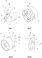
- the knife support 12 comprises a rotor 20 on which are removably mounted ten knives 30 distributed on the peripheral wall of the rotor 20.
- the number of knives can be varied, depending in particular on the flow rate (number of blades per unit time ) desired for the slicer, the size of the food to be cut, etc.
- a distribution of the knives on the rotor is however desirable to have a regular effort (and not jerk) on the drive motor.
- the rotor 20 is hollow and cylindrical here; it comprises on its peripheral wall 22 ten openings 21 for receiving the knives 30.
- the openings In the side view 3b, the openings have a substantially parallelepipedal developed section, a long side 22 form an angle with the plane (Y0, Z0).
- At the ends of each opening 21 are provided two holes 25 for fixing a knife.
- the rotor 20 has an outer diameter of about 142 mm, an internal diameter of about 128 mm; each opening 21 here has a large side 22 of about 54 mm and a small side 23 of about 12 mm; the long side 22 forms an angle of about 11.5 ° with the plane (Y0, Z0) or an angle a1 of 78.5 ° with the axis X0 of the rotor; the rotor 20 is made of stainless steel suitable for a food application.
- a first embodiment of a knife 30 is shown on the Figures 4a to 4d . It comprises a concave active blade 31 whose longitudinal edge forms a cutting edge 32; the edge 32 forms a concave arc extending in a reference plane (Y, Z) perpendicular to a reference axis (X), the reference axis being transversally to the blade.
- the active blade 31 is extended at its leading end 38 by a first fastening tab 33 and at its end end 39 by a second fastening tab 34.
- the leading end 38 of the blade 31 (or the cutting edge 32) is the end which comes into contact with the first food slicing when the support is rotating;
- the end end 39 of the blade 31 or the cutting edge 32 is the end of the cutting edge which ends the cutting of a food wafer when the rotor is rotating.
- the active blade 31 has a substantially trapezoidal section 35; when the knife is in position on the rotor, a large side 36 of the section forms, in the vicinity of the middle of the active blade (at the cutting plane AA) an opening angle a2 with the axis of the rotor.
- the long side 36 and a small side 37 of the trapezoidal section 35 together form an angle a3 and together define the cutting edge 32.
- the angle a2 is about 5 ° at the cutting plane AA
- the angle a3 is about 45 °.
- the long side 36 corresponds to a large base of the trapezoidal section
- the short side 37 corresponds to a side adjacent to the large base.
- the blade 31 is not quite symmetrical with respect to the plane A-A.
- the radius of curvature of the cutting edge in the vicinity of the end end 39 and in the vicinity of the leading end 38 is less than the radius of curvature the cutting edge near its central part (of the order of 73 mm in the example).
- a small radius of curvature in the vicinity of the leading end facilitates priming of the cut; a small radius of curvature in the vicinity of the terminal end makes it possible to obtain slices of regular thickness up to the end of the slice.
- the angle a2 varies along the blade. Between the leading end and the central portion of the blade 31, the angle a2 is substantially constant.
- the angle a2 is lower and has in the example shown a value close to zero.
- the distance between the cutting edge and an outer face of the peripheral wall of the rotor decreases in the vicinity of the terminal end of the blade.
- a transverse direction of the first fastening tab 33 extends in a plane substantially parallel to the reference axis (X); a transverse direction of the second fastening tab 34 extends in turn in a plane forming an angle ⁇ 4 of about 3 ° in the example with the reference axis (X) when the knife is not fixed on the rotor.
- Bores on the fixing lugs 33, 34 are provided to cooperate with the holes 24 of the rotor for fastening the knives by screwing ( Fig. 2 ) or riveting.
- the slicer makes it possible to produce in the food slices of length substantially equal to the length of a knife, about 54 mm, of width d ( Fig. 3b ) of the order of 10 to 12 mm and thickness e of the order of 1 to 5 mm.
- the width of the slices can be varied by varying the length of the knife blade 31 and / or the angle a1.
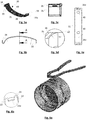
- the Figures 5a to 5d show another embodiment of a knife 30, variant of the knife represented on the Figures 4a-4c , with essentially the following differences.
- the radius of curvature of the cutting edge is equal to the radius of curvature of the rotor (of the order of 73 mm in one example) from the leading end to the central portion of the blade; the radius of curvature of the terminal part of the blade is much smaller, of the order of 13 mm in one example ( Figs. 5a, 5c ).
- the trapezoidal section of the blade ( Figs. 5c, 5d ) has a small concave side 37 (for example with a radius of curvature of the order of 1.5 mm) to have a thinner, sharper cutting edge.
- the fixing lugs 33, 34 extend in planes substantially parallel to the reference axis X of the blade and parallel to the plane (X, Y); the tab 33 extends on the side of the concavity of the blade and the tab 34 extends on the opposite side. This makes it possible, on the side of the leading end of the blade, a distance between the blade and the rotor substantially equal to the distance between the blade and the rotor at the central portion of the blade and, the next to the terminal end of the blade, a distance between the blade and the rotor zero, the blade enters the rotor somehow.
- holes 33a, 33b are provided on the fastening tabs. They have here a rectangular shape, adapted to cooperate with corresponding pads 23a on transverse faces 23 of the openings 21; the rectangular shape prevents any rotation of the knife on itself.
- the orientation of the holes 33a, 33b relative to the reference axis of the blade allows in particular to adjust the opening angle a2 of the blade relative to the peripheral wall of the rotor.
- the distance between the bores 33a, 33b and the cutting portion of the blade is chosen according to the desired distance between the cutting edge and the peripheral wall of the rotor, and therefore the desired thickness for the sliced food.
- holes 40 are provided on a top face of the blade. They form a gripping means for setting up or removing a knife from the rotor.
- FIGS. 6a, 6b show a variant of the rotor of figures 2-3 , suitable for a knife according to figures 5 .
- studs 23a are provided, positioned on the transverse faces 23 of the openings 21.
- the knives are placed on the rotor as follows: a clamp with two studs allows to take the knife while bending slightly by acting on the elasticity of the blade so as to reduce the distance between the two attachment lugs 33, 34, then to position the knife in an opening 21.
- the knife is then released and the bores 33a, 33b cooperate with the pads 23a to immobilize the knife in the desired opening in the desired orientation, without other fastening means (no screws, no rivet in particular).
- the knives of figures 4 and 5 can be made by folding a metal blade (eg a stainless steel for food application) of about 0.8 mm thick
- a metal blade eg a stainless steel for food application
- Figure 5e shows a blade before folding.
- the transverse lines in the vicinity of the holes 33a, 33b show the position of the folds intended to form the fastening tabs; the transverse line pointed by an arrow between the bore 40 and the bore 34a defines the change of radius of curvature on the blade.
- the metal can be cured by surface treatment such as TiCN, TiAlN, TiN, PVD or heat treatment).
Abstract
L'invention concerne un couteau (30) pour une trancheuse, couteau adapté pour être monté de manière amovible sur un rotor (20) creux cylindrique ou conique, couteau comprenant une lame active (31) concave dont un bord longitudinal forme une arête de coupe (32) s'étendant dans un plan de référence (Y, Z) perpendiculaire à un axe de référence (X) transversal à la lame active, couteau caractérisé en ce qu'un rayon de courbure au voisinage d'une extrémité terminale de l'arête de coupe est inférieur à un rayon de courbure au voisinage d'une partie centrale de l'arête de coupe. L'invention concerne également un support pour trancheuse, support comprenant une pluralité de couteaux tels que décrits ci-dessus et montés sur un rotor.The invention relates to a knife (30) for a slicer, knife adapted to be removably mounted on a cylindrical or conical hollow rotor (20), knife comprising a concave active blade (31) having a longitudinal edge forming a cutting edge. (32) extending in a reference plane (Y, Z) perpendicular to a reference axis (X) transverse to the active blade, knife characterized in that a radius of curvature near a terminal end of the cutting edge is less than a radius of curvature in the vicinity of a central portion of the cutting edge. The invention also relates to a support for a slicer, a support comprising a plurality of knives as described above and mounted on a rotor.
Description
La présente invention se rapporte à une trancheuse pour trancher des aliments frais et malléables tels que de la viande ou du poisson frais, notamment en des lamelles de faibles épaisseurs.The present invention relates to a slicer for slicing fresh and malleable foods such as meat or fresh fish, including thin strips.
Pour la découpe mécanisée des aliments, on connaît notamment des trancheuses comprenant un support à couteaux conique rotatif, support appelé communément cône ou tambour. Le support comprend sur sa paroi périphérique au moins une lame s'étendant dans un plan passant par l'axe de rotation du support et dont l'arête tranchante est sensiblement plane. L'aliment à trancher est amené au contact du support rotatif par un déplacement en translation selon un axe perpendiculaire à l'axe de rotation du support.For the mechanized cutting of food, slicers including a rotary conical knife support, commonly known as a cone or drum, are known. The support comprises on its peripheral wall at least one blade extending in a plane passing through the axis of rotation of the support and whose cutting edge is substantially flat. The slicing food is brought into contact with the rotary support by a displacement in translation along an axis perpendicular to the axis of rotation of the support.
De telles trancheuses sont plutôt efficaces pour la découpe d'aliments relativement durs tels que des légumes. De telles trancheuses sont également efficaces pour trancher des aliments tels que de la viande ou du poisson, mais seulement s'ils ont été durcis préalablement par une étape de congélation.Such slicers are quite effective for cutting relatively hard foods such as vegetables. Such slicers are also effective for slicing foods such as meat or fish, but only if they have been previously cured by a freezing step.
De telles trancheuses ne permettent pas de trancher des aliments mous tels que de la viande fraîche ou du poisson frais. En effet, les fibres souples de tels aliments se courbent et se déchirent mais ne sont pas coupés proprement, en particulier au bord des aliments, et en particulier pour des tranches de faible épaisseur, de l'ordre de quelques millimètres.Such slicers do not allow slicing soft foods such as fresh meat or fresh fish. In fact, the flexible fibers of such foods curl and tear but are not cut cleanly, especially at the edge of the food, and in particular for slices of small thickness, of the order of a few millimeters.
L'invention propose une nouvelle trancheuse, un nouveau support à couteaux et un couteau associés, ne présentant pas tout ou partie des inconvénients des outils connus et décrits ci-dessus.The invention proposes a new slicer, a new knife support and a knife associated, not having all or part of the disadvantages of known tools and described above.
Plus précisément, l'invention concerne un couteau pour une trancheuse, couteau adapté pour être monté dans une ouverture d'un rotor creux cylindrique ou conique ; le couteau comprend une lame active concave dont un bord longitudinal forme une arête de coupe s'étendant dans un plan de référence (Y, Z) perpendiculaire à un axe de référence (X) transversal à la lame active; un rayon de courbure au voisinage d'une extrémité terminale de l'arête de coupe est inférieur à un rayon de courbure au voisinage d'une partie centrale de l'arête de coupe.More specifically, the invention relates to a knife for a slicer, knife adapted to be mounted in an opening of a hollow cylindrical or conical rotor; the knife comprises a concave active blade whose longitudinal edge forms a cutting edge extending in a reference plane (Y, Z) perpendicular to a reference axis (X) transverse to the active blade; a radius of curvature adjacent a terminal end of the cutting edge is less than a radius of curvature in the vicinity of a central portion of the cutting edge.
L'extrémité d'attaque de l'arête est l'extrémité de l'arête de coupe qui touche en premier l'aliment à trancher lorsque la lame est entraînée en rotation. L'extrémité terminale est l'extrémité de l'arête qui termine la coupe d'une tranche d'aliment. Les fibres d'un aliment mou tel que de la viande ou du poisson frais, ont tendance à s'étirer et à s'incliner lorsque la lame appuie sur l'aliment de sorte que l'extrémité terminale de la tranche est plus difficile à trancher que l'extrémité d'attaque et que l'épaisseur de la tranche obtenue a une tendance naturelle à augmenter entre l'extrémité d'attaque de la tranche (extrémité coupée en premier) et l'extrémité terminale de la tranche (extrémité coupée à la fin) lorsque les fibres se relâchent après avoir été coupées, cassées. Des essais ont montré que qu'une diminution du rayon de courbure au voisinage de l'extrémité terminale de l'arête de coupe permet de compenser ce phénomène naturel et d'obtenir ainsi une tranche d'épaisseur plus régulière.The leading end of the ridge is the end of the cutting edge that first touches the food to be sliced when the blade is rotated. The terminal end is the end of the ridge that ends the cutting of a slice of food. The fibers of a soft food such as fresh meat or fish, tend to stretch and tilt as the blade presses the food so that the terminal end of the wafer is more difficult to slice that the leading end and the thickness of the slice obtained has a natural tendency to increase between the leading end of the slice (cut first end) and the terminal end of the slice slice (end cut at the end) when the fibers relax after being cut, broken. Tests have shown that a decrease in the radius of curvature in the vicinity of the terminal end of the cutting edge compensates for this natural phenomenon and thus obtain a slice of more regular thickness.
De préférence :
- dans la partie centrale de l'arête de coupe, le rayon de courbure de l'arête de coupe est sensiblement égal au rayon de courbure d'une surface extérieure du rotor, et
- le rayon de courbure de l'arête de coupe au voisinage de sa partie terminale est au moins deux fois inférieur au rayon de courbure de l'arête de coupe au voisinage de sa partie centrale.
- in the central portion of the cutting edge, the radius of curvature of the cutting edge is substantially equal to the radius of curvature of an outer surface of the rotor, and
- the radius of curvature of the cutting edge in the vicinity of its end portion is at least two times smaller than the radius of curvature of the cutting edge in the vicinity of its central portion.
Ainsi, dans la partie centrale de l'arête de coupe, la distance entre l'arête de coupe et le rotor est sensiblement constante et, au voisinage de la partie terminale de l'arête de coupe, la diminution sensible du rayon de courbure permet de diminuer sensiblement la distance entre l'arête de coupe et le rotor de sorte que, après relâchement des fibres étirées pendant le tranchage, les tranches d'aliment obtenus ont une épaisseur sensiblement constante sur toute leur surface.Thus, in the central part of the cutting edge, the distance between the cutting edge and the rotor is substantially constant and, in the vicinity of the end portion of the cutting edge, the substantial decrease in the radius of curvature to substantially reduce the distance between the cutting edge and the rotor so that, after loosening the fibers drawn during slicing, the food slices obtained have a substantially constant thickness over their entire surface.
Selon un mode de réalisation du couteau :
- l'arête de coupe s'étend dans le plan de référence (Y, Z) défini par un axe (Y) radial perpendiculaire à l'arête de coupe et un axe (Z) tangent à l'arête de coupe, et
- dans un plan (X, Y) défini par l'axe de référence (X) et l'axe radial (Y), la lame active présente une section sensiblement trapézoïdale, un grand côté (36) de la section trapézoïdale s'étend selon l'axe de référence (X), le grand côté (36) et un petit côté (37) de la section trapézoïdale (35) définissent ensemble l'arête de coupe (32) et forment ensemble un angle a3 inférieur à 50° au voisinage l'arête de coupe (32).
- the cutting edge extends in the reference plane (Y, Z) defined by a radial axis (Y) perpendicular to the cutting edge and an axis (Z) tangential to the cutting edge, and
- in a plane (X, Y) defined by the reference axis (X) and the radial axis (Y), the active blade has a substantially trapezoidal section, a long side (36) of the trapezoidal section extends according to the reference axis (X), the long side (36) and a short side (37) of the trapezoidal section (35) together define the cutting edge (32) and together form an angle a3 of less than 50 ° to neighbor the cutting edge (32).
La lame a ainsi une bonne tenue mécanique et la lame est suffisamment fine au niveau de l'arête de coupe pour trancher de manière nette les aliments.The blade thus has good mechanical strength and the blade is sufficiently thin at the cutting edge to slice food clearly.
Selon un mode de réalisation, le petit côté est rectiligne. Selon un autre mode de réalisation, le petit côté est concave, avec une concavité tournée vers l'extérieur comme on le verra mieux plus loin dans des exemples. La lame est ainsi plus résistante mécaniquement, tout en étant plus fine au niveau de l'arête de coupe pour une coupe plus nette. De plus, les aliments tranchés sont repoussés vers l'intérieur du rotor ce qui facilitent leur évacuation du rotor.According to one embodiment, the short side is rectilinear. According to another embodiment, the short side is concave, with an outwardly facing concavity, as will be seen later in the examples. The blade is thus more mechanically strong, while being thinner at the cutting edge for a cleaner cut. In addition, the sliced food is pushed back inside the rotor which facilitate their evacuation of the rotor.
Selon un mode de réalisation, la lame active est prolongée à son extrémité d'attaque par une première patte de fixation et à son extrémité terminale par une deuxième patte de fixation. La réalisation d'un couteau et sa mise en place sur le rotor est ainsi facilitée. La première et / ou la deuxième patte de fixation peut comprendre un perçage, adapté pour une fixation du couteau sur le rotor par rivetage, vissage ou clipsage..According to one embodiment, the active blade is extended at its leading end by a first fixing lug and at its end end by a second fixing lug. The realization of a knife and its implementation on the rotor is thus facilitated. The first and / or the second fixing lug may comprise a bore, adapted for fixing the knife on the rotor by riveting, screwing or clipping.
Selon un mode de réalisation, une direction transversale de la première patte de fixation s'étend dans un plan sensiblement parallèle à l'axe de référence (X) et une direction transversale de la deuxième patte de fixation s'étend dans un plan formant un angle a4 compris entre 0 et 10° avec l'axe de référence (X). Ainsi, la deuxième patte de fixation peut être bien plaquée contre la surface interne du rotor cylindrique, que le couteau soit positionné en biais sur le rotor (par exemple avec un angle a1 de l'ordre de 65 à 85° par rapport à l'axe de rotation (X0) du rotor), ou qu'il soit parallèle à l'axe de rotation du rotor (c'est-à-dire avec un angle de 0° par rapport à l'axe de rotation du rotor).According to one embodiment, a transverse direction of the first fastening tab extends in a plane substantially parallel to the reference axis (X) and a transverse direction of the second fastening tab extends in a plane forming a angle a4 between 0 and 10 ° with the reference axis (X). So, the second fastening tab can be pressed against the inner surface of the cylindrical rotor, that the knife is positioned obliquely on the rotor (for example with an angle a1 of the order of 65 to 85 ° with respect to the axis of rotation ( X0) of the rotor), or that it is parallel to the axis of rotation of the rotor (that is to say with an angle of 0 ° with respect to the axis of rotation of the rotor).
De préférence, les pattes de fixation d'un couteau sont en contact avec une face interne de la paroi périphérique du rotor. Les pattes de fixation s'étendent ainsi sensiblement dans le prolongement de la lame, les couteaux sont montés par l'intérieur du rotor et fixés à l'intérieur de celui-ci par exemple par des vis ou des rivets. Ainsi, les pattes de fixation et les moyens de fixation (vis, rivets, ...) ne forment pas d'irrégularité sur la face extérieure de la paroi périphérique du rotor susceptible de gêner le glissement de l'aliment à couper lors de la rotation du support à couteaux.Preferably, the fastening tabs of a knife are in contact with an inner face of the peripheral wall of the rotor. The fixing lugs thus extend substantially in the extension of the blade, the knives are mounted by the inside of the rotor and fixed to the inside thereof for example by screws or rivets. Thus, the fixing lugs and the fastening means (screws, rivets,...) Do not form an irregularity on the outer face of the peripheral wall of the rotor which may hinder the sliding of the food to be cut during the rotation of the knife support.
Selon un autre mode de réalisation, la première patte de fixation s'étend du côté de la concavité de la lame et la deuxième patte de fixation s'étend du côté opposé à la concavité de la lame. Dans ce cas, la fixation du couteau se fait de préférence dans l'épaisseur de la paroi périphérique du rotor, comme on le verra mieux plus loin dans un exemple. Ainsi, il n'y a pas d'irrégularité sur la face interne de la paroi périphérique du rotor.According to another embodiment, the first fastening tab extends on the side of the concavity of the blade and the second fastening tab extends on the opposite side to the concavity of the blade. In this case, the attachment of the knife is preferably in the thickness of the peripheral wall of the rotor, as will be seen better later in an example. Thus, there is no irregularity on the inner face of the peripheral wall of the rotor.
Enfin, sur la lame du couteau peut également être prévu un moyen de préhension, constitué dans un exemple de deux perçages, pour faciliter la mise en place du couteau sur le rotor, et son démontage. Cela facilite grandement la maintenance (aiguisage) ou le remplacement du couteau.Finally, on the blade of the knife can also be provided a gripping means, consisting in an example of two holes, to facilitate the introduction of the knife on the rotor, and its disassembly. This greatly facilitates the maintenance (sharpening) or replacement of the knife.
L'invention concerne également un support à couteaux pour une trancheuse d'aliments ; le support est agencé pour être monté rotatif sur un axe d'entraînement de la trancheuse ; le rotor est creux, cylindrique ou conique ; le rotor comprend sur sa paroi périphérique une pluralité de couteaux comprenant au moins un couteau tel que décrit ci-dessus. Notamment, la lame du couteau est concave et un rayon de courbure au voisinage d'une extrémité terminale de l'arête de coupe de la lame est inférieur à un rayon de courbure au voisinage d'une partie centrale de l'arête de coupe.The invention also relates to a knife support for a food slicer; the support is arranged to be rotatably mounted on a drive axis of the slicer; the rotor is hollow, cylindrical or conical; the rotor comprises on its peripheral wall a plurality of knives comprising at least one knife as described above. In particular, the blade of the knife is concave and a radius of curvature in the vicinity of an end end of the cutting edge of the blade is less than a radius of curvature in the vicinity of a central portion of the cutting edge.
La concavité spécifique de l'arête de coupe se traduit par une épaisseur de coupe plus faible sur le bord terminal de coupe qu'au centre de la coupe. L'épaisseur à trancher est ainsi plus faible sur le bord terminal, la coupe est plus facile, bien plus net, y compris avec des aliments mous.The specific concavity of the cutting edge results in a lower cutting thickness on the cutting edge at the center of the cut. The thickness to slice is thus lower on the terminal edge, the cut is easier, much clearer, including soft foods.
Une distance entre la lame et une face externe de la paroi périphérique du rotor peut diminuer au voisinage de l'extrémité terminale de l'arête de coupe dans le plan de référence. La coupe est ainsi encore facilitée et plus nette.A distance between the blade and an outer face of the peripheral wall of the rotor may decrease in the vicinity of the terminal end of the cutting edge in the reference plane. The cut is thus even easier and sharper.
L'arête de coupe peut former un arc concave s'étendant dans le plan de référence formant de préférence un angle de 65 à 85° en valeur absolue par rapport à l'axe (X0) du support. Lors de la rotation du support, la lame attaque ainsi progressivement l'aliment à trancher, ce qui facilite encore la réalisation d'une coupe nette, y compris avec un aliment mou.The cutting edge may form a concave arc extending in the reference plane preferably forming an angle of 65 to 85 ° in absolute value with respect to the axis (X0) of the support. When rotating the support, the blade attacks thus gradually the slicing food, which further facilitates the achievement of a clean cut, including with a soft food.
Selon un mode de réalisation, dans un plan parallèle à un axe de référence du couteau (X) et perpendiculaire au plan de référence (Y, Z), la lame active présente une section sensiblement trapézoïdale, un grand côté de la dite section étant parallèle à l'axe de référence (X) et formant un angle d'ouverture a2 de 0 à 10° avec l'axe du rotor (X0). La paroi interne de la lame concave, légèrement inclinée (angle d'ouverture a2 entre 0 et 10°) va guider la tranche d'aliment coupée vers l'intérieur du support, comme on le verra mieux plus loin dans la description du mode de réalisation représenté sur les dessins. Le choix de l'angle d'ouverture permet également d'influer sur l'épaisseur de la tranche.According to one embodiment, in a plane parallel to a reference axis of the knife (X) and perpendicular to the reference plane (Y, Z), the active blade has a substantially trapezoidal section, a large side of said section being parallel to the reference axis (X) and forming an aperture angle a2 of 0 to 10 ° with the axis of the rotor (X0). The inner wall of the concave blade, slightly inclined (opening angle a2 between 0 and 10 °) will guide the slice of food cut towards the inside of the support, as will be seen better later in the description of the mode of embodiment shown in the drawings. The choice of the opening angle also affects the thickness of the wafer.
Selon une variante, l'angle d'ouverture diminue entre une partie centrale et une extrémité terminale de l'arête de coupe. Une diminution de l'angle d'ouverture entre la partie centrale et l'extrémité terminale de la lame permet de compenser encore plus le phénomène d'étirement des fibres lors de la coupe d'aliments mous et d'obtenir ainsi une tranche d'épaisseur plus régulière encore.According to one variant, the opening angle decreases between a central portion and an end end of the cutting edge. A decrease in the opening angle between the central part and the end of the blade makes it possible to compensate even more for the stretching of the fibers during the cutting of soft foods and thus to obtain a slice of even more regular thickness.
De préférence, l'angle d'ouverture est inférieur à 1° au voisinage de l'extrémité terminale de l'arête de coupe. Ainsi, l'épaisseur de la coupe est quasi nulle à la fin de la coupe et la coupe est nette.Preferably, the opening angle is less than 1 ° in the vicinity of the terminal end of the cutting edge. Thus, the thickness of the cut is almost zero at the end of the cut and the cut is clear.
Le rotor comprend de préférence sur sa paroi périphérique pluralité d'ouvertures dans lesquelles sont montés une pluralité de couteaux tels que décrits ci-dessous. La réalisation en deux parties, rotor et couteaux, facilite la réalisation de l'ensemble. Si de plus, les couteaux sont montés amovibles, l'entretien (aiguisage, remplacement) des couteaux est également facilité. De plus, il devient possible de réaliser des tranches d'épaisseur différente, en changeant les couteaux sur un même rotor ou à l'inverse en changeant le rotor pour les mêmes couteaux, en prenant par exemple un rotor de même diamètre interne mais diamètre externe différent.The rotor preferably comprises on its peripheral wall a plurality of openings in which are mounted a plurality of knives as described below. The realization in two parts, rotor and knives, facilitates the realization of the whole. If, moreover, the knives are mounted removable, the maintenance (sharpening, replacement) of the knives is also facilitated. In addition, it becomes possible to make slices of different thickness, by changing the knives on the same rotor or conversely by changing the rotor for the same knives, for example by taking a rotor of the same internal diameter but external diameter different.
Ainsi, selon un mode de réalisation, les pattes de fixation des couteaux sont rivetées ou vissées contre une face interne de la paroi périphérique du rotor. Selon un autre mode de réalisation, des évidements percés dans les pattes de fixation des couteaux coopèrent avec des plots correspondants positionnés sur des faces transversales des ouvertures prévues dans la paroi du rotor.Thus, according to one embodiment, the fastening tabs of the knives are riveted or screwed against an inner face of the peripheral wall of the rotor. According to another embodiment, recesses pierced in the fastening tabs of the knives cooperate with corresponding studs positioned on transverse faces of the openings provided in the wall of the rotor.
L'invention sera mieux comprise, et d'autres caractéristiques et avantages de l'invention apparaîtront à la lumière de la description qui suit d'exemples de réalisation d'un support à couteau et d'un couteau selon l'invention. Ces exemples sont donnés à titre non limitatif. La description est à lire en relation avec les dessins annexés dans lesquels :
- la
figure 1 est une vue en perspective éclatée d'une lamelleuse selon l'invention, - la
figure 2 est une vue en perspective d'un support à couteaux selon l'invention, - les
figure 3a et 3b sont respectivement une vue en perspective et une vue de côté du rotor du support à couteaux de lafigure 2 , - les
figures 4a à 4c sont respectivement une vue en perspective, une vue de face et une vue de côté d'un couteau du support à couteau de lafigure 2 , - la
figure 4d montre un détail de lafigure 4c , - les
figures 5a à 5c sont respectivement une vue en perspective, une vue de face et une vue de côté d'une variante de couteau, - la
figure 5d montre un détail de lafigure 5c , - la figure 5e montre un mode de réalisation d'un couteau selon les
figures 5a à 5c , - la
figure 6a montre un principe de mise en place d'un couteau selon lesfigures 5a à 5c et - la
figure 6b montre un détail de lafigure 6a .
- the
figure 1 is an exploded perspective view of a laminator according to the invention, - the
figure 2 is a perspective view of a knife support according to the invention, - the
Figure 3a and 3b are respectively a perspective view and a side view of the rotor of the knife support of thefigure 2 , - the
Figures 4a to 4c are respectively a perspective view, a front view and a side view of a knife of the knife holder of thefigure 2 , - the
figure 4d shows a detail of thefigure 4c , - the
Figures 5a to 5c are respectively a perspective view, a front view and a side view of a knife variant, - the
figure 5d shows a detail of thefigure 5c , - FIG. 5e shows an embodiment of a knife according to the
Figures 5a to 5c , - the
figure 6a shows a principle of setting up a knife according toFigures 5a to 5c and - the
figure 6b shows a detail of thefigure 6a .
Sur les différentes figures, les mêmes références désignent des éléments identiques ou similaires.In the different figures, the same references designate identical or similar elements.
Pour tout ce qui suit, on définit les axes et les plans suivants.
- X0 est l'axe de rotation du support
- Y0, Z0 sont deux axes définissant un plan perpendiculaire à l'axe X0, Y0 est un axe radial coupant l'axe X0,
- (X0, Y0, Z0) est un repère orthogonal direct lié au rotor.
- (Y, Z) est un plan de référence dans lequel s'étend l'arête de coupe d'un couteau , Z est un axe tangent à l'arête de coupe, Y est un axe radial perpendiculaire à l'arête de coupe et à l'axe Z
- X est un axe de référence perpendiculaire au plan de référence (Y, Z), X est un axe transversal de la lame active,
- (X, Y0) est le plan de coupe A-A représenté sur la
fig. 4b - (X, Y, Z) est un repère orthogonal direct lié à la lame.
- X0 is the axis of rotation of the support
- Y0, Z0 are two axes defining a plane perpendicular to the axis X0, Y0 is a radial axis intersecting the axis X0,
- (X0, Y0, Z0) is a direct orthogonal reference linked to the rotor.
- (Y, Z) is a reference plane in which the cutting edge of a knife extends, Z is an axis tangential to the cutting edge, Y is a radial axis perpendicular to the cutting edge and to the Z axis
- X is a reference axis perpendicular to the reference plane (Y, Z), X is a transverse axis of the active blade,
- (X, Y0) is the cutting plane AA shown on the
Fig. 4b - (X, Y, Z) is a direct orthogonal reference linked to the slide.
Comme dit précédemment, l'invention concerne une trancheuse d'aliments, et plus particulièrement un support à couteaux pour une telle trancheuse. L'invention est particulièrement bien adaptée pour couper des aliments de consistance molle tels que de la viande ou du poisson frais, en lamelles de faible épaisseur, idéales pour la réalisation de plats tels que des émincés, tartares au couteau ou dentelle boeuf.As said above, the invention relates to a food slicer, and more particularly a knife support for such a slicer. The invention is particularly well suited for cutting soft-consistency foods such as meat or fresh fish, thin slices, ideal for making dishes such as minced, knife tartar or lace beef.
La
La trancheuse fonctionne de la manière suivante. Les aliments à trancher positionnés dans le bac sont poussés en translation par un appui sur la poignée du couvercle 11 en direction du support à couteaux entraîné en rotation. Chaque couteau tranche une lamelle d'aliment qui descend dans le rotor creux ; chaque lamelle est ensuite entraînée naturellement vers l'extérieur du rotor, poussée par les lamelles suivantes.The slicer works as follows. Slicing food positioned in the tray are pushed in translation by pressing on the handle of the
Dans l'exemple représenté sur les
Le rotor 20 est creux et cylindrique ici ; il comprend sur sa paroi périphérique 22 dix ouvertures 21 destinées à recevoir les couteaux 30. Sur la vue de côté 3b, les ouvertures présentent une section développée sensiblement parallélépipédique dont un grand côté 22 forment un angle avec le plan (Y0, Z0). Aux extrémités de chaque ouverture 21 sont prévus deux trous 25 pour la fixation d'un couteau. Dans l'exemple représenté, le rotor 20 a un diamètre externe de 142 mm environ, un diamètre interne de l'ordre de 128 mm ; chaque ouverture 21 a ici un grand côté 22 de 54 mm environ et un petit côté 23 de 12 mm environ ; le grand côté 22 forme un angle de 11.5° environ avec le plan (Y0, Z0) soit un angle a1 de 78,5° environ avec l'axe X0 du rotor ; le rotor 20 est réalisé en inox adapté à une application alimentaire.The
Un premier mode de réalisation d'un couteau 30 est représenté sur les
Dans un plan A-A parallèle à l'axe de référence (X) et à l'axe radial (Y) (
La lame 31 n'est pas tout-à-fait symétrique par rapport au plan A-A. En particulier, le rayon de courbure de l'arête tranchante au voisinage de l'extrémité terminale 39 et au voisinage de l'extrémité d'attaque 38 (de l'ordre de 13 mm dans un exemple), est inférieur au rayon de courbure de l'arête tranchante au voisinage de sa partie centrale (de l'ordre de 73 mm dans l'exemple). Un faible rayon de courbure au voisinage de l'extrémité d'attaque facilite l'amorçage de la coupe ; un faible rayon de courbure au voisinage de l'extrémité terminale permet d'obtenir des tranches d'épaisseur régulière jusqu'à l'extrémité de la tranche. Egalement ici, l'angle a2 varie le long de la lame. Entre l'extrémité d'attaque et la partie centrale de la lame 31, l'angle a2 est sensiblement constant. Par contre, au voisinage de l'extrémité terminale de la lame, l'angle a2 est plus faible et a dans l'exemple représenté une valeur proche de zéro. Enfin, lorsque le couteau est en place sur le rotor, la distance entre l'arête de coupe et une face externe de la paroi périphérique du rotor diminue au voisinage de l'extrémité terminale de la lame.The
Comme on le voit plus particulièrement sur la
Dans l'exemple représenté
Les
Les pattes de fixation 33, 34 s'étendent dans des plans sensiblement parallèles à l'axe de référence X de la lame et parallèles au plan (X, Y) ; la patte 33 s'étend du côté de la concavité de la lame et la patte 34 s'étend du côté opposé. Cela permet d'avoir, du côté de l'extrémité d'attaque de la lame, une distance entre la lame et le rotor sensiblement égale à la distance entre la lame et le rotor au niveau de la partie centrale de la lame et, du côté de l'extrémité terminale de la lame, une distance entre la lame et le rotor nulle, la lame rentre dans le rotor en quelque sorte.The fixing lugs 33, 34 extend in planes substantially parallel to the reference axis X of the blade and parallel to the plane (X, Y); the
Egalement, des perçages 33a, 33b sont prévus sur les pattes de fixation. Ils ont ici une forme rectangulaire, apte à, coopérer avec des plots 23a correspondants sur des faces transversales 23 des ouvertures 21 ; la forme rectangulaire permet d'interdire toute rotation du couteau sur lui-même. L'orientation des perçages 33a, 33b par rapport à l'axe de référence de la lame permet notamment d'ajuster l'angle d'ouverture a2 de la lame par rapport à la paroi périphérique du rotor. Egalement, la distance entre les perçages 33a, 33b et la partie tranchante de la lame est choisie en fonction de la distance souhaitée entre l'arête tranchante et la paroi périphérique du rotor, et donc de l'épaisseur souhaitée pour les aliments tranchés.Also,
Enfin deux perçage 40 sont prévu sur une face de dessus de la lame. Ils forment un moyen de préhension pour la mise en place ou le retrait d'un couteau du le rotor.Finally two
Les
Bien sûr, de nombreuses variantes des couteaux des
Les couteaux des
- 1010
-
trancheuse
11 couvercle de dessus
12 support à couteaux
13 évidement
14 bouchon
R axe de rotationslicer
11 top cover
12 knife holder
13 recess
14 stopper
R axis of rotation - 2020
-
rotor
21 pluralité d'ouvertures
22 face longitudinale (grand côté) d'une ouverture 21
23 face transversale (petit côté) d'une ouverture 21
23a plot
24 trous
a1 angle d'inclinaison du grand côté 22 par rapport à l'axe X0
25 paroi périphérique
26 face interne de la paroi 25
27 face externe de la paroi 25rotor
21 plurality of openings
22 longitudinal side (long side) of anopening 21
23 transverse face (short side) of anopening 21
23a plot
24 holes
a1 angle of inclination of thelong side 22 with respect to the axis X0
25 peripheral wall
26 inner face of thewall 25
27 outer face ofwall 25
- 3030
-
couteau
31 lame active
32 arête de coupe
33, 33a première patte de fixation, perçage
34, 34a deuxième patte de fixation, perçage
a4 angle de la patte 34 par rapport à l'axe X
35 section trapézoïdale de la lame active
36 grand côté
a2 angle du grand côté 36 par rapport à l'axe X
37 petit côté
a3 angle au niveau de l'arête de coupe
38 extrémité d'attaque de la lame 31
39 extrémité terminale de la lame 31
40 deux perçage formant moyen de préhension du couteauknife
31 active blade
32 cutting edge
33, 33a first fixing lug, drilling
34, 34a second bracket, drilling
a4 angle of theleg 34 with respect to the X axis
35 trapezoidal section of the active blade
36 big side
a2 angle of thelong side 36 with respect to the X axis
37 little side
a3 angle at the cutting edge
38 leading end of theblade 31
39 terminal end of theblade 31
40 two holes forming a gripping means for the knife
Claims (15)
Applications Claiming Priority (1)
| Application Number | Priority Date | Filing Date | Title |
|---|---|---|---|
| FR1550400A FR3031692A1 (en) | 2015-01-19 | 2015-01-19 | KNIFE AND ROTATING KNIFE HOLDER WITH HOLLOW ROTOR FOR FOOD SLICER |
Publications (1)
| Publication Number | Publication Date |
|---|---|
| EP3045276A1 true EP3045276A1 (en) | 2016-07-20 |
Family
ID=52779882
Family Applications (1)
| Application Number | Title | Priority Date | Filing Date |
|---|---|---|---|
| EP16020013.5A Withdrawn EP3045276A1 (en) | 2015-01-19 | 2016-01-19 | Blade and rotary blade mounting with hollow rotor for food slicer |
Country Status (2)
| Country | Link |
|---|---|
| EP (1) | EP3045276A1 (en) |
| FR (1) | FR3031692A1 (en) |
Cited By (1)
| Publication number | Priority date | Publication date | Assignee | Title |
|---|---|---|---|---|
| WO2018078549A1 (en) * | 2016-10-28 | 2018-05-03 | Pires De Sousa Joao Manuel | Method and device for producing a rotisserie meat product, a meat product of this type and device for cutting off pieces thereof |
Citations (5)
| Publication number | Priority date | Publication date | Assignee | Title |
|---|---|---|---|---|
| GB191081A (en) * | 1921-12-31 | 1923-11-08 | Heinrich Harder | Machine for the cutting and/or shredding of vegetables and other foodstuffs |
| US5095875A (en) * | 1989-06-21 | 1992-03-17 | Carl Morris | Knife for producing waffle and lattice cuts |
| EP2529902A1 (en) * | 2011-06-01 | 2012-12-05 | Seb S.A. | Tool for cutting food into pieces |
| US20130276604A1 (en) * | 2012-04-23 | 2013-10-24 | Urschel Laboratories Inc. | Methods and equipment for cutting food products |
| WO2014067489A1 (en) * | 2012-11-05 | 2014-05-08 | 北京银河星辰科技有限公司 | Rotary cutting type food processor |
-
2015
- 2015-01-19 FR FR1550400A patent/FR3031692A1/en active Pending
-
2016
- 2016-01-19 EP EP16020013.5A patent/EP3045276A1/en not_active Withdrawn
Patent Citations (5)
| Publication number | Priority date | Publication date | Assignee | Title |
|---|---|---|---|---|
| GB191081A (en) * | 1921-12-31 | 1923-11-08 | Heinrich Harder | Machine for the cutting and/or shredding of vegetables and other foodstuffs |
| US5095875A (en) * | 1989-06-21 | 1992-03-17 | Carl Morris | Knife for producing waffle and lattice cuts |
| EP2529902A1 (en) * | 2011-06-01 | 2012-12-05 | Seb S.A. | Tool for cutting food into pieces |
| US20130276604A1 (en) * | 2012-04-23 | 2013-10-24 | Urschel Laboratories Inc. | Methods and equipment for cutting food products |
| WO2014067489A1 (en) * | 2012-11-05 | 2014-05-08 | 北京银河星辰科技有限公司 | Rotary cutting type food processor |
Cited By (1)
| Publication number | Priority date | Publication date | Assignee | Title |
|---|---|---|---|---|
| WO2018078549A1 (en) * | 2016-10-28 | 2018-05-03 | Pires De Sousa Joao Manuel | Method and device for producing a rotisserie meat product, a meat product of this type and device for cutting off pieces thereof |
Also Published As
| Publication number | Publication date |
|---|---|
| FR3031692A1 (en) | 2016-07-22 |
Similar Documents
| Publication | Publication Date | Title |
|---|---|---|
| CH632179A5 (en) | WEAR PLATE DEVICE OF A PORTABLE MECHANICAL KNIFE. | |
| EP3324802B1 (en) | Food preparation device having at least one rotary spiral cutting tool | |
| GB2462282A (en) | Culinary utensil | |
| FR2876616A1 (en) | VEGETABLE CUTTER SECURITY MANUAL | |
| EP3187051B1 (en) | Apparatus for dividing sausages into portions, winding around a plate and provided with a cutting tool | |
| FR2948053A1 (en) | ASSEMBLY AND METHOD FOR CLEANING A GRID | |
| EP0203016B1 (en) | Cutting device, especially between two zones with a different hardness | |
| EP3045276A1 (en) | Blade and rotary blade mounting with hollow rotor for food slicer | |
| EP0493229B1 (en) | Apparatus for removing waste from cut sheets of cardboard and the like | |
| EP1329182B1 (en) | Rotating knife for apparatus for food preparation and apparatus with such a knife | |
| EP1813177A1 (en) | spatula for kitchen use | |
| FR2726780A1 (en) | Cook's mandoline for slicing foodstuff | |
| FR2682062A1 (en) | Cutter (knife) intended to make several mutually parallel cuts simultaneously in a food product | |
| FR2979213A1 (en) | Device for cutting and peeling fruit i.e. breadfruit and root-vegetable i.e. dasheen, has disk-shaped honeycomb structure including sliding connectors that allow user to expand or reduce diameter of connecting regions | |
| FR3033997A1 (en) | PUZZLE EGG | |
| FR2891129A1 (en) | Vegetable slicer for use in food processors comprises rotating disk with radial blade mounted above it and fitted with peripheral collar, on same side as blade, which has radial indent which fits over outer tip of blade | |
| FR2693936A1 (en) | Cutting disc for a kitchen appliance. | |
| EP2108293B1 (en) | Appliance for mechanical treatment of food comprising a potato-masher device | |
| FR2510025A3 (en) | Blade for electric knife - has spaced, tapered triangular teeth with points alternating between major blade faces | |
| EP2923808A1 (en) | Fruit or vegetable knife | |
| FR2941884A1 (en) | Cheese grater/vegetable cutting disk for e.g. electric vegetable cutter, has cutting parts formed by corrugated metal strip, where corrugations of strip have cutting portions projected on face and portions embedded in body by overmolding | |
| FR2681807A1 (en) | DEVICE FOR SLICING MUSHROOMS. | |
| FR2892289A1 (en) | Food e.g. carrot, processing apparatus for hotel industry, has elastic insert guiding food across spout and having tongues moved with respect to insertion axis of food in insert and supported perpendicularly against food | |
| FR3104398A1 (en) | Manually operated device for parallel and regular slicing of soft food products | |
| FR2755389A1 (en) | Cutter for scarifying types of bread |
Legal Events
| Date | Code | Title | Description |
|---|---|---|---|
| PUAI | Public reference made under article 153(3) epc to a published international application that has entered the european phase |
Free format text: ORIGINAL CODE: 0009012 |
|
| AK | Designated contracting states |
Kind code of ref document: A1 Designated state(s): AL AT BE BG CH CY CZ DE DK EE ES FI FR GB GR HR HU IE IS IT LI LT LU LV MC MK MT NL NO PL PT RO RS SE SI SK SM TR |
|
| AX | Request for extension of the european patent |
Extension state: BA ME |
|
| STAA | Information on the status of an ep patent application or granted ep patent |
Free format text: STATUS: THE APPLICATION IS DEEMED TO BE WITHDRAWN |
|
| 18D | Application deemed to be withdrawn |
Effective date: 20170121 |