EP3044129B2 - Abruf-/lagervorrichtung für automatische lagersysteme - Google Patents
Abruf-/lagervorrichtung für automatische lagersysteme Download PDFInfo
- Publication number
- EP3044129B2 EP3044129B2 EP14790294.4A EP14790294A EP3044129B2 EP 3044129 B2 EP3044129 B2 EP 3044129B2 EP 14790294 A EP14790294 A EP 14790294A EP 3044129 B2 EP3044129 B2 EP 3044129B2
- Authority
- EP
- European Patent Office
- Prior art keywords
- retrieval
- opening
- wall
- walls
- storage surface
- Prior art date
- Legal status (The legal status is an assumption and is not a legal conclusion. Google has not performed a legal analysis and makes no representation as to the accuracy of the status listed.)
- Active
Links
Images


Classifications
-
- B—PERFORMING OPERATIONS; TRANSPORTING
- B65—CONVEYING; PACKING; STORING; HANDLING THIN OR FILAMENTARY MATERIAL
- B65G—TRANSPORT OR STORAGE DEVICES, e.g. CONVEYORS FOR LOADING OR TIPPING, SHOP CONVEYOR SYSTEMS OR PNEUMATIC TUBE CONVEYORS
- B65G1/00—Storing articles, individually or in orderly arrangement, in warehouses or magazines
- B65G1/02—Storage devices
- B65G1/04—Storage devices mechanical
- B65G1/06—Storage devices mechanical with means for presenting articles for removal at predetermined position or level
-
- B—PERFORMING OPERATIONS; TRANSPORTING
- B65—CONVEYING; PACKING; STORING; HANDLING THIN OR FILAMENTARY MATERIAL
- B65G—TRANSPORT OR STORAGE DEVICES, e.g. CONVEYORS FOR LOADING OR TIPPING, SHOP CONVEYOR SYSTEMS OR PNEUMATIC TUBE CONVEYORS
- B65G1/00—Storing articles, individually or in orderly arrangement, in warehouses or magazines
- B65G1/02—Storage devices
- B65G1/04—Storage devices mechanical
- B65G1/137—Storage devices mechanical with arrangements or automatic control means for selecting which articles are to be removed
-
- B—PERFORMING OPERATIONS; TRANSPORTING
- B65—CONVEYING; PACKING; STORING; HANDLING THIN OR FILAMENTARY MATERIAL
- B65G—TRANSPORT OR STORAGE DEVICES, e.g. CONVEYORS FOR LOADING OR TIPPING, SHOP CONVEYOR SYSTEMS OR PNEUMATIC TUBE CONVEYORS
- B65G1/00—Storing articles, individually or in orderly arrangement, in warehouses or magazines
- B65G1/02—Storage devices
- B65G1/04—Storage devices mechanical
- B65G1/10—Storage devices mechanical with relatively movable racks to facilitate insertion or removal of articles
-
- E—FIXED CONSTRUCTIONS
- E06—DOORS, WINDOWS, SHUTTERS, OR ROLLER BLINDS IN GENERAL; LADDERS
- E06B—FIXED OR MOVABLE CLOSURES FOR OPENINGS IN BUILDINGS, VEHICLES, FENCES OR LIKE ENCLOSURES IN GENERAL, e.g. DOORS, WINDOWS, BLINDS, GATES
- E06B9/00—Screening or protective devices for wall or similar openings, with or without operating or securing mechanisms; Closures of similar construction
- E06B9/02—Shutters, movable grilles, or other safety closing devices, e.g. against burglary
- E06B9/08—Roll-type closures
- E06B9/11—Roller shutters
- E06B9/15—Roller shutters with closing members formed of slats or the like
Definitions
- the present invention relates to a retrieval/storage apparatus for automatic warehouses, according to the preamble of claim 1.
- the present invention further relates to an automatic warehouse equipped with a respective apparatus that enables the retrieval and/or storage of various kinds of articles inside the automatic warehouse.
- the warehouse lends itself particularly well to managing drawers in the form of a substantially flat tray, which are arranged vertically one above the other in a respective shelf structure.
- Each drawer is suitable for containing one or more articles, based on the size and type of the articles, which can for example consist of work tools or common objects of small and medium-sized dimensions.
- warehouses have access zones, in which the operator removes the article from the respective drawer or places the article in the drawer for the purpose of storing it inside the warehouse.
- the drawers are moved automatically by means of a logical control unit, which, based on the article selected by the operator, brings the respective drawer containing that article into the access zone.
- each drawer is automatically moved into the access zone by means of a sliding carriage controlled accordingly by the control unit.
- the carriage slides preferably vertically, passing along stacks of trays arranged in columns, and via suitable engagement means draws a given drawer into the access zone.
- the known automatic warehouses can be of two types, depending on the arrangement of the access zone: with an internal bay or an external bay.
- the access zone is defined by an opening formed in the weight-bearing structure of the warehouse, in which the selected drawer is positioned.
- the drawer always remains inside the footprint of the warehouse and the operator accesses the inside of the opening.
- the access zone is defined outside the warehouse, since the drawer is moved by the carriage outside an opening formed in the weight-bearing structure of the warehouse.
- the carriage can be provided with an extendable support, which causes the selected drawer to come out of the aforesaid opening.
- the drawer is made to project outside the footprint of the warehouse to allow the operator facilitated access to the drawer.
- the drawer In both types of warehouses, the drawer is generally provided with a retrieval/storage system that allows the operator correct access to the desired article.
- This system is made up of a series of cover flaps positioned on an upper surface of the drawer, each of which is suitable for enabling access to a respective housing space provided in the drawer.
- the flaps can be opened automatically by the logic control unit to allow the operator to remove or position the article correctly.
- the number and size of the flaps will vary depending on the internal spaces of the drawer and hence on the articles contained. However, in order to standardize the dimensions of the spaces and of the respective cover flaps, use is generally made of drawers having flaps of identical dimensions and the same number of spaces for containing articles.
- retrieval/storage systems have a major drawback due precisely to the need to standardize the spaces and the respective flaps, with the consequent difficulty of adapting the dimensions of containment of the articles that must be stored in the warehouse.
- an appropriate flip-up system is constructed and designed for the respective space in the drawer.
- the drawers can also be always open to allow the operator, once in the access zone, to retrieve the article desired or position it freely inside the volume defined by the drawer.
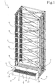
- 1 indicates overall an automatic warehouse warehouse, provided with a respective retrieval/storage apparatus 2.
- the warehouse 1 of the present invention is preferably of the type endowed with a shelf-type support structure 3 for accommodating respective drawers 4 (better illustrated in figure 3 ).
- the structure 3 preferably has a parallelepiped shape and defines a series of housings 5 positioned one above the other along one or more vertical columns.
- the housings 5 are designed to contain, in a storage configuration, the respective drawers 4, which are in this manner stacked.
- the housings 5 are illustrated empty (in the absence of the drawers 4) in order to better view the structure of the entire warehouse 1.
- An access zone 6 extending at the base of the support structure 3 is adapted to allow the retrieval and/or storage of one or more articles (not illustrated, as they are not part of the present invention) contained in the drawers 4.
- the warehouse 1 is endowed with respective automatic, suitably motorized means 7 for handling the drawers 4, and for moving each drawer 4 between an idle position in which it is housed in the housing seat 5 and a position of access wherein it is positioned in the access zone 6.
- the handling means 7, which are not described and illustrated in detail, as they are of a known type, are controlled by a programmable logic control unit that can be operated by a user.
- the means 7 consist of a carriage that moves along a path formed in the structure 3 so as to move each drawer 4 between the respective idle and access position.
- the means 7 retrieve the corresponding drawer 4 to bring it into the access zone 6.
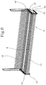
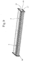
- FIG. 3 there is illustrated a drawer 4 from which an article is retrieved or by means of which the article is stored in the warehouse warehouse 1.
- the drawer 4 preferably has a tray-like conformation, with a substantially rectangular periphery and in which there is defined an opening 4a for accessing a containment volume 4b.
- the access opening 4a extends along the whole drawer 4 in order to maintain open access to the volume 4b.
- the articles (not illustrated) are accommodated inside the volume 4b, preferably according to predefined positions based on the size and number of the articles themselves.
- Said drawer has a containment volume 4b, preferably parallelepiped shaped, open at the top through the access opening 4a.
- Said drawer 4 having, in a plan view, a preferably quadrangular perimeter, is defined by a right side 41, a left side 42, a front side 43 and a back side 44.
- Front side 43 means the side of the drawer 4 which, when the latter is placed inside the bay (external or internal), is farther from the handling means 7, i.e. closer to the operator positioned in front of the bay (external or internal), whereas back side 44 means the side of the drawer 4 which, when the latter is placed inside the bay (external or internal), is opposite the previous one and thus closer to the handling means 7, i.e. farther from the operator positioned in front of the bay (external or internal).
- the drawer 4 can comprise predefined partitions 45 serving to define, inside the drawer 4, a division into compartments of varying width depending on the articles contained.
- the drawer 4 can have the volume 4b completely open, or else divided into spaces of a size determined by the manufacturer or spaces of a size determined by the user, by applying the partitions 45 inside the drawer 4.
- the warehouse warehouse 1 further comprises a retrieval/storage apparatus 2 located in the aforesaid access zone 6.
- the apparatus 2 can be used irrespective of the type of warehouse 1 and with any configuration of the access zone 6.
- the warehouse in figures 1 and 4 to 6 is of the external bay type
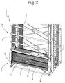
- the warehouse illustrated in figure 2 and figures 7 to 9 is of the internal bay type.
- the external bay warehouse in figure 1 has an access zone 6 in a portion that is external to the structure 3, outside the footprint defined by the structure 3 itself.
- the access zone 6 is defined in a portion located inside the structure 3 and thus inside the overall footprint of the warehouse warehouse 1.
- the retrieval/storage apparatus 2 has a support frame 8 having a retrieval/storage level 9 for at least one article which must be retrieved from the warehouse 1 or stored in the warehouse 1.
- the support frame 8 which will be better described further below in the present illustration, defines a housing space 10 for a drawer 4.
- the housing space 10 is in communication with the path of the handling means 7 to enable the drawer 4 to be housed in the space 10 or be moved away from the space 10.
- the surface 9 extends above the space 10 and lies in a horizontal plane at a suitable height so as to be accessible by an operator.
- Said retrieval/storage level 9 has, in a plan view, a preferably quadrangular perimeter defined by at least a first edge 9a, a second edge 9b, a third edge 9c and a fourth edge 9d.
- Access means 11 extend over the surface 9 and are operatively active on the surface 9 itself so as to open/close at least one opening 12 through which it is possible to access the inside of the housing space 10.
- Said at least one opening 12 has a closed contour defined by at least a first side 12a, a second side 12b, a third side 12c and a fourth side 12d.
- the drawer 4 is housed in the space 10 to enable retrieval/storage of the article.
- the access means 11 define the opening 12 according to the positioning of the article to be retrieved, which, as specified above is in a predefined area of the drawer 4.
- the means 11 determine an opening to allow the operator to access the drawer 4 and at the same time they close off said opening 12 so as to determine a completely closed surface 9.
- the aforesaid access means 11 preferably consist of a first and a second wall 13, 14 both mobile along the retrieval/storage level 9 in reciprocal approaching/distancing.
- the means 11 also have a fourth wall 16 mobile along the retrieval/storage level 9 in reciprocal approaching/distancing with the third wall 15.
- the aforementioned opening 12 is defined by the cooperation of the first, second and third walls 13, 14, 15.
- first side 12a is defined by a terminal end of the first wall 13
- second side 12b is defined by a terminal end of the second wall 14
- third and the fourth sides 12c, 12d are defined by the terminal ends of the third wall 15.
- the first wall 13 is bent over the containment volume 4b, above the same, and has at least one portion extending away from the left side 42 of the drawer 4 to block off, at least partially, the access opening 4a
- the second wall 14 is bent over the containment volume 4b, above the same, and has at least one portion extending away from the right side 41 of the drawer 4 to block off, at least partially the access opening 4a
- the third wall 15 is bent over the containment volume 4b, enveloping the front side 43, and has both portions extending away from the front side 43 of the drawer 4 to block off, at least partially the access opening 4a.
- the first wall 13 is bent over like a C above the containment volume 4b, with the bent over portion extending in proximity to the left side 42
- the second wall is bent over like a C above the containment volume 4b, in opposition to the previous one, with the bent over portion in proximity to the right side 41
- the third wall 15 is bent over like a C so as to envelop the containment volume 4b, that is, with the portions situated above and below the containment volume 4b, and the bent over portion in proximity to the front side 43.
- the aforementioned opening 12 is defined by the cooperation of the first, second, third and fourth walls 13, 14, 15, 16.
- first side 12a is defined by a terminal end of the first wall 13
- second side 12b is defined by a terminal end of the second wall 14
- third side 12c is defined by a terminal end of the third wall 15
- fourth side 12d is defined by a terminal end of the fourth wall 16.
- the first wall 13 is bent over the containment volume 4b, above the same, and has at least one portion extending away from the left side 42 of the drawer 4 to block off, at least partially, the access opening 4a
- the second wall 14 is bent over the containment volume 4b, above the same, and has at least one portion extending away from the right side 41 of the drawer 4 to block off, at least partially, the access opening 4a
- the third wall 15 is bent over the containment volume 4b, enveloping the front side 43, and has at least one portion extending away from the front side 43 of the drawer 4 to block off, at least partially, the access opening 4a
- the fourth wall 16 is bent over the containment volume 4b, above the same, and has at least one portion extending away from the back side 44 of the drawer 4 to block off, at least partially, the access opening 4a.
- the first wall 13 is bent over like a C above the containment volume 4b, with bent over portion extending in proximity to the left side 42
- the second wall is bent over like a C above the containment volume 4b, in opposition to the previous one, with the bent over portion extending in proximity to the right side 41
- the third wall 15 is bent over like a C to envelop the containment volume 4b, that is, with the portions situated above and below the containment volume 4b
- the bent over portion extending in proximity to the front side 43 and the fourth wall 16 is bent over like an L above the containment volume 4b, with the bent over portion extending in proximity to the back side 44.
- the conformation of the fourth wall 16 is such as to protect the operator by inhibiting access to the handling means 7.
- the walls 13, 14, 15 and 16 are mobile along the retrieval/storage level 9, in a configuration of reciprocal approaching/distancing so as to define the aforementioned opening 12 or completely block off the area defined by the surface 9.
- first and the second walls 13, 14s are slidable along the retrieval/storage level of 9 in a longitudinal direction of extension X of the frame 8.
- the third and fourth walls 15, 16 are in contrast slidable along the retrieval/storage level 9 in a transversal direction of extension Y.
- walls 13, 14, 15 and 16 extend in respective superimposed lying surfaces, parallel to each other and parallel to the retrieval/storage level 9.
- the walls can at least partially overlap so as to completely close off the surface 9 in the condition of non-access to drawer 4.
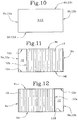
- Figure 10 illustrates a configuration of maximum opening of the retrieval/storage level 9 and complete superimposition of the at least one window 12 over the surface 9.
- the area subtended by the least one opening 12 is equal to the area subtended by the surface 9.
- This configuration used for example for operations of filling and/or completely emptying the drawer 4 or for operations of inspecting the drawer 4, is achieved through the superimposition, or superimposed lying, of the first, second, third and fourth sides 12a-12d, of the opening 12 on the respective first, second, third, and fourth edges 9a-9d of the surface.
- first, second and third walls 13,14,15 are completely open, i.e. not situated above the surface 9.
- Figure 11 illustrates a first configuration of partial opening of the retrieval/storage level 9 and of partial superimposition of the at least one window 12 over the surface 9.
- the area subtended by the at least one opening 12 is smaller than the one subtended by the surface 9.
- This configuration used for operations of retrieval and/or storage inside the drawer 4 and analogous and opposite to the one represented in figure 12 , is achieved through the superimposition, or superimposed lying, of at least three sides of the opening 12 on the respective and contiguous edges of the surface 9.
- condition of coincidence, or complete superimposition, between one side of the opening 12 and a respective edge of the surface 9, as for example in figure 11 between the first side 12a and the first edge 9a can occur either by superimposition of the terminal portion of the wall 13-16 on the contiguous edge or by distancing of the terminal portion of the wall 13-16 from the contiguous edge of the retrieval and storage surface.
- the first side 12a coincides with the first edge 9a
- the second side 12b extends parallel to and is not superimposed on the corresponding second edge 9b
- the third side 12c lies, without coinciding, on the third edge 9c
- the fourth side 12d lies, without coinciding, on the fourth edge 9d.
- the first side 12a lies, without coinciding, on the first edge 9a, just as the second side 12b lies, without coinciding, on the respective second edge 9b
- the third side 12c extends parallel and is not superimposed on the corresponding third edge 9c and the fourth side 12d coincides with the fourth edge 9d.
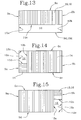
- Figure 14 illustrates another first configuration of partial opening of the retrieval/storage surface 9 and of partial superimposition of the at least one window 12 over the surface 9.
- the area subtended by the at least one opening 12 is smaller than the one subtended by the surface 9.
- This configuration again used for operations of retrieval and/or storage inside the drawer 4, similar to the ones represented in figures 14-15 , is achieved through the superimposition, or superimposed lying, of at least two sides of the opening 12 on respective contiguous edges of the surface 9.
- the first side 12a lies, without coinciding, on the first edge 9a and the third side 12c lies, without coinciding, on the third edge 9c.
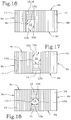
- Figure 18 illustrates a second intermediate configuration of partial opening of the retrieval/storage surface 9 and of non-superimposition, or non-intersection, of the at least one window 12 with the surface 9.
- the area subtended by the at least one opening 12 is smaller than the one subtended by the surface 9.
- This configuration again used for operations of retrieval and/or storage inside the drawer 4, is achieved through the non-superimposition, or non-superimposed lying, of all sides of the opening 12 on the respective edges of the surface 9.
- each wall 13,14,15,16 can be of the shutter type driven by a respective motor so as to form an open-loop system, that is, one in which each wall is not closed in a loop.
- each wall 13,14,15,16 can be of the shutter type or fabric type drawn by at least one chain, in turn conveyed on suitable motorized guides, so as to form an open-loop system.
- each wall 13,14,15,16 can be of the shutter type, or, alternatively, fabric type, drawn by a system of belts, or, alternatively, a chain, so as to form a closed-loop system, that is, one in which each wall, or at least the respective guide belt system, is closed in a loop.
- each wall 13, 14, 15 and 16 consists of a shutter slidable along a respective path 13', 14', 15', 16' which extends according to a substantially arcuate configuration around the housing space 10 of the drawer 4.
- Each wall 13, 14, 15 and 16 is moved by means of respective motors of a known type, preferably provided with drive belts to convey the walls along the respective paths.
- the walls are made to slide along the corresponding path between a position of maximum dimensions in which they block off the entire area defined by the retrieval/storage surface 9 and a position of minimum dimensions in which they are positioned over the retrieval/storage surface 9.
- the frame 8 has a box-shaped structure, having a parallelepiped shape with a rectangular base.
- retrieval/storage surface 9 is defined on an upper outer surface of the box-shaped structure of the frame 8.
- the apparatus 2 is illustrated in detail with some parts removed to better illustrate the slidable walls.
- the covering walls 17 that define the exposed exterior of the box-shaped structure of the frame 8 have been removed.
- the fourth wall 16 slides along a path 16' defined by respective sliding guides 18 arranged above the retrieval and storage surface 9.
- the sliding guides 18 form a closed loop and have a portion lying over the surface 9 and parallel to a transversal side of the box-shaped structure of the frame 8.
- the third wall 15 extends along a "C-shaped" path 15' that extends around a lateral face of the box-shaped extension of the frame 8. As is illustrated in figure 5 , in which the fourth wall 16 has been removed, the third wall 15 slides along guides 19 that likewise form a closed loop and have at least one portion lying along the surface 9.
- the third and fourth walls 15, 16 are slidable according to a motion of coming and going reciprocally closer and farther apart to determine the opening 12.
- first and second walls 13, 14 are slidable around the frame 8 and along respective substantially semicircular paths 13', 14', facing and opposite each other.
- Each path 13', 14' is determined by respective guides 20, 21 extending circumferentially around the peripheral longitudinal extension of the box-shaped structure of the frame 8.
- first and second walls 13, 14 are slidable according to a motion of coming and going reciprocally closer and farther apart to determine the opening 12.
- box-shaped structure of the frame 8 comprises an opening (not visible in the appended figures) for accessing the housing space 10 of the drawer 4, fashioned along a side adjacent to the retrieval/storage surface 9.
- the opening is opposite the side where the third wall 15 extends and is equal in width to the peripheral longitudinal extension of the box-shaped structure of the frame 8.
- This access opening enables the entry/exit of the drawer 4 into/from the space 10.
- the presence of the mobile walls 13, 14, 15 and 16 and respective sliding guides does not interfere with the movement of the drawer 4 through the aforementioned access opening.
- the frame 8 has a substantially annular structure with a peripheral rectangular extension internally defining the retrieval/storage zone 6.
- the retrieval/storage surface 9 is provided at a lower internal surface of the aforementioned annular structure of the frame 8.
- first and second walls 13, 14 are illustrated in detail, both slidable around respective semicircular paths 13', 14', which are opposite and facing each other and defined by the peripheral longitudinal extension of the annular structure of the frame 8.
- both the first and second walls slide according to a motion of coming and going reciprocally closer and farther apart along sliding guides 22, 23 that both have a portion passing through the surface 9.
- each guide 22, 23 forms a closed loop and each corresponding wall is suitably motorized with a motor that is not illustrated and described, as it is of a known type.
- the third and fourth wall 15, 16 are slidable beneath the first and second wall 13, 14 along the lower inner surface of the aforementioned annular structure of the frame 8.
- the third wall 15 extends along a C-shaped path 15' entirely situated beneath the frame 8.
- the path 15' is determined by sliding guides 24 forming a closed loop, each positioned on a transversal edge of the frame 8.
- the path 15' of the third wall 15 extends at least partially around the containment space 10 of the drawer 4. In this manner, the space 10 has an access opening for the entry/exit of the drawer 4 into/from the space 10.
- the fourth wall 16 extends along a semi-annular path 16' extending at least partially along a side of the frame 8, opposite an open side for accessing the retrieval and storage zone 6.
- the fourth wall 16 slides along the surface 9 and in a side of the frame 8 adjacent to said surface 9.
- the third and fourth walls 15, 16 are motor driven in a motion of coming and going reciprocally closer and farther apart.
- the apparatus 2 enables precise access to the space 10 and thus inside the drawer 4.
- the apparatus 2 is very versatile and adaptable to any type and size of article contained in the drawer 4.
- the present apparatus including the automatic warehouse warehouse equipped with at least one apparatus, has a high level of flexibility of application: it is a single device for all the drawers.
- the adoption of drawers a wide range of products of different sizes and shapes can be contained, with the possibility of arranging the products inside the drawer itself in any manner. Therefore, this enables a reduction in the costs of designing the apparatus, thanks to the format of the drawer used to contain the product, and in particular its internal layout.
Landscapes
- Engineering & Computer Science (AREA)
- Mechanical Engineering (AREA)
- Structural Engineering (AREA)
- Architecture (AREA)
- Civil Engineering (AREA)
- Warehouses Or Storage Devices (AREA)
- Drawers Of Furniture (AREA)
- Vending Machines For Individual Products (AREA)
Claims (26)
- Entnahme-/Lagervorrichtung für Warenlager, umfassend:einen Tragrahmen (8), der eine Entnahme-/Lagerfläche (9) für mindestens einen Artikel aufweist, der aus einem jeweiligen Warenlager (1) entnommen oder im Warenlager (1) gelagert werden muss;wobei der Rahmen (8) einen Gehäuseraum (10) für eine Schublade (4) zur Aufnahme eines oder mehrerer der Artikel definiert;wobei der Rahmen (8) eine kastenförmige Struktur aufweist;Zugangsmittel (11), die auf der Entnahme-/Lagerfläche (9) betriebsmäßig aktiv sind, um mindestens eine Öffnung (12) zu öffnen/schließen, durch die es möglich ist, auf den Gehäuseraum (10) innerhalb der Schublade (4) zuzugreifen;wobei die Zugangsmittel (11) eine erste und eine zweite Wand (13, 14), die sich beide entlang der Entnahme-/Lagerfläche (9) in gegenseitiger Annäherung/Entfernung bewegen; eine dritte Wand (15), die sich entlang der Entnahme-/Lagerfläche (9) in einer Richtung quer zur Ausdehnungsrichtung der ersten und zweiten Wand (13, 14) bewegt, und eine vierte Wand (16), die sich entlang der Entnahme-/Lagerfläche (9) in gegenseitiger Annäherung/Entfernung zur dritten Wand (15) bewegt, umfassen;dadurch gekennzeichnet, dass der Gehäuseraum (10) eine Zugangsöffnung aufweist, die entlang einer der Entnahme-/Lagerfläche (9) benachbarten Seite zum Ein-/Ausfahren der Schublade (4) in den/aus dem Gehäuseraum (10) ausgebildet ist; und dass jede der ersten, zweiten, dritten und vierten Wände (13, 14, 15, 16) aus einem entlang einer jeweiligen Bahn (13', 14', 15', 16') verschiebbaren Verschluss besteht, der sich nach einer im Wesentlichen gebogenen Konfiguration um den Gehäuseraum (10) der Schublade (4) herum erstreckt, so dass die Zugangsöffnung des Gehäuseraums (10) nicht behindert wird.
- Vorrichtung nach Anspruch 1, dadurch gekennzeichnet, dass die mindestens eine Öffnung (12) eine geschlossene Kontur aufweist, die durch mindestens eine erste Seite (12a), eine zweite Seite (12b), eine dritte Seite (12c) und eine vierte Seite (12d) definiert ist.
- Vorrichtung nach Anspruch 2, dadurch gekennzeichnet, dass die erste und zweite Wand (13, 14) jeweils eine erste und eine zweite Seite (12a, 12b) definieren und, dass die dritte Wand (15) eine dritte und vierte Seite (12c, 12d) der mindestens einen Öffnung (12) definiert.
- Vorrichtung nach Anspruch 1, dadurch gekennzeichnet, dass die Schublade (4), die ein Aufnahmevolumen (4b) aufweist, das durch die Zugangsöffnung (4a) oben offen ist, durch mindestens eine rechte Seite (41), eine linke Seite (42), eine Vorderseite (43) und eine Rückseite (44) definiert ist.
- Vorrichtung nach Anspruch 4, dadurch gekennzeichnet, dass die Zugangsmittel (11), wenn sie auf der Entnahme-/Lagerfläche (9) betriebsmäßig aktiv sind, zum Öffnen der mindestens einen Öffnung (12) Folgendes aufweisen: die erste Wand (13), die auf das Aufnahmevolumen (4b) gebogen ist und sich von der linken Seite (42) weg erstreckt, um die Zugangsöffnung (4a) mindestens teilweise zu blockieren; die zweite Wand (14), die auf das Aufnahmevolumen (4b) gebogen ist und sich von der rechten Seite (41) weg erstreckt, um die Zugangsöffnung (4a) mindestens teilweise zu blockieren; die dritte Wand (15), die auf das Aufnahmevolumen (4b) gebogen ist und dabei die Vorderseite (43) umhüllt und sich gegenseitig von dieser weg erstreckt, um die Zugangsöffnung (4a) mindestens teilweise zu blockieren.
- Vorrichtung nach Anspruch 1, dadurch gekennzeichnet, dass die Entnahme-/Lagerfläche (9) eine geschlossene, vorzugsweise viereckige Kontur aufweist, die durch mindestens eine erste Kante (9a), eine zweite Kante (9b), eine dritte Kante (9c) und eine vierte Kante (9d) definiert ist.
- Vorrichtung nach den Ansprüchen 2 und 6, dadurch gekennzeichnet, dass die Zugangsmittel (11), wenn sie auf der Entnahme-/Lagerfläche (9) betriebsmäßig aktiv sind, zum Öffnen der mindestens einen Öffnung (12), mindestens eine der folgenden Konfigurationen definieren:- eine Konfiguration aus maximaler Öffnung und vollständiger Überlagerung, wobei die mindestens eine Öffnung (12) einem Bereich zugrunde liegt, der gleich dem der Entnahme-/Lagerfläche (9) zugrunde liegenden Bereich ist; wobei die erste Wand (13) eine erste Seite (12a) definiert, die der ersten Kante (9a) überlagert ist; die zweite Wand (14) die zweite Seite (12b) definiert, die der zweiten Kante (9b) überlagert ist; die dritte Wand (15) die dritte und vierte Seite (12c, 12d) definiert, die jeweils der dritten und vierten Kante (9c, 9d) überlagert sind;- eine erste Konfiguration aus Zwischenöffnung und teilweiser Überlappung, wobei die mindestens eine Öffnung (12) einem Bereich zugrunde liegt, der kleiner als der der Entnahme-/Lagerfläche (9) zugrunde liegenden Bereich ist; die erste und zweite Wand (13, 14) jeweils die erste und zweite Seite (12a, 12b) der Öffnung (12) definieren; die dritte Wand (15) die dritte und vierte Seite (12c, 12d) der Öffnung (12) definiert; mindestens eine Seite (12a, 12b, 12c, 12d) der Öffnung (12) einer jeweiligen Kante (9a, 9b, 9c, 9d) der Entnahme-/Lagerfläche (9) überlagert ist.- eine zweite Konfiguration aus Zwischenöffnung und fehlender Überlagerung, wobei die mindestens eine Öffnung (12) einem Bereich zugrunde liegt, der kleiner als der der Entnahme-/Lagerfläche (9) zugrunde liegenden Bereich ist; die erste und die zweite Wand (13, 14) jeweils die erste und zweite Seite (12a, 12b) der Öffnung (12) definieren; die dritte Wand (15) die dritte und vierte Seite (12c, 12d) der Öffnung (12) definiert; alle Seiten (12a, 12b, 12c, 12d) der Öffnung (12) den jeweiligen angrenzenden Kanten (9a, 9b, 9c, 9d) der Entnahme-/Lagerfläche (9), nicht überlagert sind.
- Vorrichtung nach Anspruch 2, dadurch gekennzeichnet, dass die erste und zweite Wand (13, 14) jeweils eine erste und eine zweite Seite (12a, 12b) der Öffnung (12) definieren und, dass die dritte und vierte Wand (15, 16) jeweils eine dritte und vierte Seite (12c, 12d) der Öffnung (12) definieren.
- Vorrichtung nach Anspruch 6, dadurch gekennzeichnet, dass die Zugangsmittel (11), wenn sie auf der Entnahme-/Lagerfläche (9) betriebsmäßig aktiv sind, zum Öffnen der mindestens einen Öffnung (12), mindestens eine der folgenden Konfigurationen definieren:- eine Konfiguration aus maximaler Öffnung und vollständiger Überlagerung, wobei die mindestens eine Öffnung (12) einem Bereich zugrunde liegt, der gleich dem der Entnahme-/Lagerfläche (9) zugrunde liegenden Bereich ist; wobei die erste Wand (13) eine erste Seite (12a) definiert, die der ersten Kante (9a) überlagert ist; die zweite Wand (14) die zweite Seite (12b) definiert, die der zweiten Kante (9b) überlagert ist; die dritte Wand (15) die dritte Seite (12c) definiert, die der dritten Kante (9c) überlagert ist, die vierte Wand (16) die vierte Seite (13d) definiert, die der vierten Kante (9d) überlagert ist;- eine erste Konfiguration aus Zwischenöffnung und teilweiser Überlagerung, wobei die mindestens eine Öffnung (12) einem Bereich zugrunde liegt, der kleiner als der der Entnahme-/Lagerfläche (9) zugrunde liegenden Bereich ist; die erste und zweite Wand (13, 14) jeweils die erste und zweite Seite (12a, 12b) der Öffnung (12) definieren; die dritte und vierte Wand (15, 16) jeweils die dritte und vierte Seite (12c, 12d) der Öffnung (12) definieren; mindestens eine Seite (12a, 12b, 12c, 12d) der Öffnung (12) einer jeweiligen Kante (9a, 9b, 9c, 9d) der Entnahme-/Lagerfläche (9) überlagert ist.- eine zweite Konfiguration aus Zwischenöffnung und fehlender Überlagerung, wobei die mindestens eine Öffnung (12) einem Bereich zugrunde liegt, der kleiner als der der Entnahme-/Lagerfläche (9) zugrunde liegenden Bereich ist; die erste und die zweite Wand (13, 14) jeweils die erste und zweite Seite (12a, 12b) der Öffnung (12) definieren; die dritte und vierte Wand (15, 16) jeweils die dritte und vierte Seite (12c, 12d) der Öffnung (12) definieren; alle Seiten (12a, 12b, 12c, 12d) der Öffnung (12) den jeweiligen angrenzenden Kanten (9a, 9b, 9c, 9d) der Entnahme-/Lagerfläche (9) nicht überlagert sind.
- Vorrichtung nach Anspruch 1, dadurch gekennzeichnet, dass die erste und zweite Wand (13, 14) entlang der Entnahme-/Lagerfläche (9) in einer longitudinalen Erstreckungsrichtung (X) des Rahmens (8) verschiebbar sind, und dass die dritte Wand (15) entlang der Entnahme-/Lagerfläche (9) in einer transversalen Erstreckungsrichtung (Y) des Rahmens (8) verschiebbar ist; wobei die longitudinale (X) und die transversale (Y) Richtung senkrecht zueinander sind.
- Vorrichtung nach Anspruch 1, dadurch gekennzeichnet, dass die erste und zweite Wand (13, 14) entlang der Entnahme-/Lagerfläche (9) in einer longitudinalen Erstreckungsrichtung (X) des Rahmens (8) verschiebbar sind, und dass die dritte und vierte Wand (15, 16) entlang der Entnahme-/Lagerfläche (9) in einer transversalen Erstreckungsrichtung (Y) des Rahmens (8) verschiebbar sind; wobei die longitudinale (X) und die transversale (Y) Richtung senkrecht zueinander sind.
- Vorrichtung nach Anspruch 1, dadurch gekennzeichnet, dass die erste, zweite, dritte und vierte Wand (13, 14, 15, 16) sich auf jeweils überlagert liegenden Flächen erstrecken, die parallel zueinander und parallel zur Entnahme-/Lagerfläche (9) sind.
- Vorrichtung nach Anspruch 1, dadurch gekennzeichnet, dass jede der ersten, zweiten, dritten und vierten Wand (13, 14, 15, 16) einen entlang einer vorgegebenen, um den Gehäuseraum (10) der Schublade (4) herum definierten Bahn (13', 14', 15', 16') beweglichen Verschluss umfasst.
- Vorrichtung nach dem vorhergehenden Anspruch, dadurch gekennzeichnet, dass jede der ersten, zweiten, dritten und vierten Wand (13, 14, 15, 16) jeweils motorisierte Mittel umfasst, um den Verschluss entlang der entsprechenden Bahn (13', 14', 15', 16') zwischen einer Position bei maximalen Abmessungen, in der er den gesamten durch die Entnahme-/Lagerfläche (9) definierten Bereich blockiert, und einer Position bei minimalen Abmessungen zu verschieben, in der er nicht in der Entnahme-/Lagerfläche (9) aufgenommen ist.
- Vorrichtung nach Anspruch 1, dadurch gekennzeichnet, dass der Rahmen (8) eine externe Entnahmeöffnung mit einer kastenförmigen Struktur ist, die eine quaderförmige Gestalt mit einer rechteckigen Basis aufweist, wobei die Entnahme-/Lagerfläche (9) an einer äußeren und oberen Fläche der kastenförmigen Struktur angeordnet ist.
- Vorrichtung nach Anspruch 15, dadurch gekennzeichnet, dass die erste und zweite Wand (13, 14) um den Rahmen (8) herum und entlang einer im Wesentlichen halbkreisförmigen Bahn (13', 14') verschiebbar sind, die durch die Längsausdehnung in Umfangsrichtung der kastenförmigen Struktur des Rahmens (8) definiert ist.
- Vorrichtung nach Anspruch 16, dadurch gekennzeichnet, dass die dritte Wand (15) oberhalb der ersten und zweiten Wand (13, 14), um den Rahmen (8) herum und entlang einer im Wesentlichen halbkreisförmigen Bahn (15') verschiebbar ist, die durch die Längsausdehnung in Umfangsrichtung der kastenförmigen Struktur des Rahmens (8) definiert ist.
- Vorrichtung nach Anspruch 15, dadurch gekennzeichnet, dass die vierte Wand (16) oberhalb der ersten und zweiten Wand (13, 14) entlang einer Bahn (16') verschiebbar ist, die durch jeweilige verschiebbare Führungen (18) definiert ist, die oberhalb der Entnahme-/Lagerfläche (9) angeordnet sind.
- Vorrichtung nach Anspruch 1, dadurch gekennzeichnet, dass der Rahmen (8) eine interne Entnahmeöffnung mit einer ringförmigen Struktur und einer im Wesentlichen rechteckigen Längsausdehnung in Umfangsrichtung ist, die intern einen Entnahme-/Lagerbereich (6) definiert, wobei die Entnahme-/Lagerfläche (9) an einer inneren und unteren Fläche der ringförmigen Struktur angeordnet ist.
- Vorrichtung nach dem vorhergehenden Anspruch, dadurch gekennzeichnet, dass die erste und zweite Wand (13, 14) um den Rahmen herum und entlang einer im Wesentlichen halbkreisförmigen Bahn (13', 14') verschiebbar sind, die durch die Längsausdehnung in Umfangsrichtung der ringförmigen Struktur des Rahmens (8) definiert ist.
- Vorrichtung nach Anspruch 20, dadurch gekennzeichnet, dass die dritte Wand (15) unterhalb der ersten und zweiten Wand (13, 14) an der inneren und unteren Fläche der ringförmigen Struktur des Rahmens (8) und entlang einer im Wesentlichen halbkreisförmigen Bahn (15') verschiebbar ist, die sich mindestens teilweise um den Gehäuseraum (10) der Schublade (4) herum erstreckt.
- Vorrichtung nach Anspruch 21, dadurch gekennzeichnet, dass die vierte Wand (16) unterhalb der ersten und zweiten Wand (13, 14) an den inneren und unteren Flächen der ringförmigen Struktur des Rahmens (8) und entlang einer im Wesentlichen halbringförmigen Bahn (16') verschiebbar ist, die durch eine Längsausdehnung in Umfangsrichtung der ringförmigen Struktur des Rahmens (8) definiert ist.
- Vorrichtung nach dem vorhergehenden Anspruch, dadurch gekennzeichnet, dass die halbringförmige Bahn (16') der vierten Wand (16) sich mindestens teilweise entlang einer Seite des Rahmens (8) gegenüber einer offenen Seite erstreckt, um auf den Entnahme- und Lagerbereich (6) zuzugreifen.
- Automatisches Lager umfassend:eine Tragstruktur (3) einer Vielzahl von Schubladen (4) zur Aufnahme von Artikeln, die entnommen/gelagert werden müssen;mindestens einen in der Tragstruktur (3) definierten Zugangsbereich (6), um die Entnahme aus und/oder das Lagern in einer oder mehreren Schubladen (4) eines oder mehrerer Artikel zu ermöglichen;Handhabungsmittel (7) der Schubladen (4), um jede Schublade (4) zwischen einer Ruheposition, in der sie in jeweiligen Gehäuseräumen (5) der Struktur (3) gelagert sind, und einer Zugangsposition, in der sie in den mindestens einen Zugangsbereich (6) angeordnet sind, um die Entnahme/das Lagern von einem oder mehreren in den Schubladen (4) aufgenommenen Artikeln zu ermöglichen;dadurch gekennzeichnet, dass es außerdem mindestens eine Entnahme-/Lagervorrichtung (2) nach irgendeinem der vorhergehenden Ansprüche umfasst, die in den mindestens einen Zugangsbereich (6) angeordnet ist.
- Warenlager nach dem vorhergehenden Anspruch, dadurch gekennzeichnet, dass die Handhabungsmittel (7) der Schublade (4) sich entlang einer in der Struktur (3) ausgebildeten Bahn erstrecken, um jede Schublade (4) zwischen der jeweiligen Ruhe- und Zugangsposition zu bewegen, wobei der Gehäuseraum (10) des Rahmens (8) der Vorrichtung (2) in Kommunikation mit der Bahn steht.
- Warenlager nach dem vorhergehenden Anspruch, dadurch gekennzeichnet, dass die Schublade (4) in der jeweiligen Zugangsposition im Raum (10) des Rahmens (8) untergebracht ist und, dass die Schublade (4), wenn sie im Raum (10) des Rahmens (8) aufgenommen ist, mindestens eine Zugangsöffnung (4a) zu einem oder mehreren in der Schublade (4) selbst enthaltenen Artikeln aufweist, die der Entnahme-/Lagerfläche (9) der Vorrichtung (2) zugewandt ist.
Applications Claiming Priority (2)
| Application Number | Priority Date | Filing Date | Title |
|---|---|---|---|
| IT000252A ITMO20130252A1 (it) | 2013-09-13 | 2013-09-13 | "apparecchiatura di prelievo/stoccaggio per magazzini automatici" |
| PCT/IB2014/063715 WO2015036879A1 (en) | 2013-09-13 | 2014-08-05 | Retrieval/storage apparatus for automatic warehouse systems |
Publications (3)
| Publication Number | Publication Date |
|---|---|
| EP3044129A1 EP3044129A1 (de) | 2016-07-20 |
| EP3044129B1 EP3044129B1 (de) | 2017-11-08 |
| EP3044129B2 true EP3044129B2 (de) | 2021-03-17 |
Family
ID=49354811
Family Applications (1)
| Application Number | Title | Priority Date | Filing Date |
|---|---|---|---|
| EP14790294.4A Active EP3044129B2 (de) | 2013-09-13 | 2014-08-05 | Abruf-/lagervorrichtung für automatische lagersysteme |
Country Status (12)
| Country | Link |
|---|---|
| US (1) | US10053287B2 (de) |
| EP (1) | EP3044129B2 (de) |
| JP (1) | JP6535009B2 (de) |
| KR (1) | KR102339051B1 (de) |
| CN (1) | CN105705442B (de) |
| CA (1) | CA2923966C (de) |
| CL (1) | CL2016000541A1 (de) |
| ES (1) | ES2655089T5 (de) |
| IT (1) | ITMO20130252A1 (de) |
| MX (1) | MX369335B (de) |
| PH (1) | PH12016500489B1 (de) |
| WO (1) | WO2015036879A1 (de) |
Cited By (1)
| Publication number | Priority date | Publication date | Assignee | Title |
|---|---|---|---|---|
| DE202024100265U1 (de) | 2024-01-18 | 2024-02-23 | Maschinenfabrik Mönninghoff Gmbh & Co. Kg | Gefach für Regale, insbesondere für Tablare, sowie damit ausgestattetes Regal sowie Computerprogrammprodukt und Verwendung derartiger Gefache |
Families Citing this family (21)
| Publication number | Priority date | Publication date | Assignee | Title |
|---|---|---|---|---|
| GB2538104B (en) * | 2015-05-08 | 2018-07-11 | Asda Stores Ltd | A system for collection of products, and related collection point and methods |
| ITUA20162546A1 (it) * | 2016-04-13 | 2017-10-13 | Modula S P A Con Socio Unico | "dispositivo di prelievo e deposito selettivo di articoli per un magazzino automatico" |
| US10322878B2 (en) | 2017-07-21 | 2019-06-18 | Amazon Technologies, Inc. | Storage module having inventory carriers that are elongate along a lateral direction to carry a plurality of storage containers |
| US11358793B2 (en) | 2017-01-17 | 2022-06-14 | Amazon Technologies, Inc. | Stackable inventory storage modules, storage systems, and methods of using the same |
| US10815082B2 (en) * | 2017-10-30 | 2020-10-27 | Amazon Technologies, Inc. | Inventory storage module having a conveying loop with vertical lift |
| US11312571B2 (en) | 2017-01-17 | 2022-04-26 | Amazon Technologies, Inc. | Stackable inventory storage modules, storage systems, and methods of using the same |
| US10696480B2 (en) | 2017-07-21 | 2020-06-30 | Amazon Technologies, Inc. | Storage module configured to accelerate transition of inventory carriers between upper and lower tracks |
| EP3595989A1 (de) * | 2017-03-15 | 2020-01-22 | Berkshire Grey, Inc. | Systeme und verfahren zum speichern, wiederauffinden und verarbeiten von objekten mit stapelbaren halbrunden türmen |
| IT201700089864A1 (it) | 2017-08-03 | 2019-02-03 | Icam S R L | Dispositivo di accesso selettivo per una stazione di prelievo/deposito in un magazzino, e stazione di prelievo/deposito provvista di tale dispositivo di accesso selettivo |
| US10807798B1 (en) | 2017-10-31 | 2020-10-20 | Amazon Technologies, Inc. | Inventory storage module having actuators that move storage totes around a conveyor loop |
| US11059668B1 (en) | 2018-01-16 | 2021-07-13 | Amazon Technologies, Inc. | Stackable inventory storage module, system, and method of using the same |
| CN108820443A (zh) * | 2018-06-30 | 2018-11-16 | 浙江唐艺织物整理有限公司 | 一种植绒布料放置架 |
| NO344944B1 (en) * | 2018-10-12 | 2020-07-27 | Autostore Tech As | An access station for picking storage containers |
| CN109457867B (zh) * | 2018-11-02 | 2021-02-19 | 温州锦瑞建设有限公司 | 一种装饰柱 |
| IT201800010669A1 (it) * | 2018-11-28 | 2020-05-28 | Makros Srl | Archivio compattabile |
| TWI866948B (zh) | 2019-01-31 | 2024-12-21 | 日商湯山製作所股份有限公司 | 盒子處理裝置和藥劑處理裝置 |
| IT201900024976A1 (it) * | 2019-12-20 | 2021-06-20 | Modula S P A | Dispositivo di bloccaggio elevatore per magazzino automatico verticale |
| IT201900025408A1 (it) * | 2019-12-23 | 2021-06-23 | Tecnomeccanica Magrini S R L | Magazzino automatico. |
| IT202000000985A1 (it) * | 2020-01-20 | 2021-07-20 | Icam S R L | Dispositivo di accesso selettivo per una stazione di prelievo/deposito in un magazzino, e stazione di prelievo/deposito provvista di tale dispositivo di accesso selettivo |
| IT202000019882A1 (it) * | 2020-08-10 | 2022-02-10 | Sintesi Srl | Armadio automatizzato per la custodia e la distribuzione a richiesta di articoli |
| CN118451035A (zh) * | 2021-12-27 | 2024-08-06 | 摩登纳股份公司 | 用于室内栽培的自动化仓库及相关栽培方法 |
Family Cites Families (27)
| Publication number | Priority date | Publication date | Assignee | Title |
|---|---|---|---|---|
| DE221575C (de) | ||||
| US1857368A (en) * | 1930-05-06 | 1932-05-10 | John E Flynn | Curtain device |
| SE347120B (de) * | 1969-12-23 | 1972-07-24 | C Ohlson | |
| JPS58178229A (ja) | 1982-04-12 | 1983-10-19 | Chino Works Ltd | 光学的測定装置 |
| JPS6052403A (ja) | 1983-08-08 | 1985-03-25 | Nippon Filing Co Ltd | 機密物保管設備 |
| JPS6085508U (ja) * | 1983-11-17 | 1985-06-12 | 村田機械株式会社 | 自動倉庫 |
| JPS61206709A (ja) | 1985-03-07 | 1986-09-13 | Motoda Electronics Co Ltd | トレ−配送装置 |
| DE4017329C1 (en) | 1990-05-30 | 1992-01-09 | Welle Gmbh & Co Kg, 4790 Paderborn, De | Cabinet roll front for office furniture - has independently moving parts which are interconnected by cords and rollers |
| JP2607463Y2 (ja) * | 1992-07-14 | 2001-09-04 | 株式会社椿本チエイン | 物品保管棚のスライド式物品入出庫機構 |
| EP0599032A1 (de) * | 1992-11-23 | 1994-06-01 | Manitec Consulting AG | Behälterlager |
| US5820237A (en) * | 1995-10-27 | 1998-10-13 | Bellheimer Metallwerk Gmbh | Vertical stacking system using controlled access method |
| DE29718758U1 (de) | 1997-10-22 | 1998-01-02 | Rau GmbH, 72336 Balingen | Werkzeugwagen |
| DE19927248C2 (de) | 1999-06-15 | 2001-06-21 | Haenel & Co Altstaetten | Lagerregal |
| IT1315679B1 (it) | 2000-10-05 | 2003-03-14 | Nuova C G A Sistemi Srl | Parete di chiusura di area definita |
| US6561250B2 (en) * | 2001-08-08 | 2003-05-13 | Chanel, Inc. | Display device |
| US6694221B2 (en) | 2001-10-23 | 2004-02-17 | Dispensesource, Inc. | Controlled inventory device and method using pressure transducer |
| EP1357247A1 (de) | 2002-04-17 | 2003-10-29 | Garny Sicherheitstechnik GmbH | Wertdepoteinrichtung |
| US6994409B2 (en) | 2002-07-02 | 2006-02-07 | Dispensesource, Inc. | Controlled access dispensing system |
| JP2007126270A (ja) | 2005-11-07 | 2007-05-24 | Sumita System:Kk | ピッキング装置 |
| WO2009057166A1 (en) | 2007-10-29 | 2009-05-07 | Hen S.R.L. | An automatic warehouse |
| DE102008027646A1 (de) * | 2008-06-05 | 2009-12-17 | LÜTH & DÜMCHEN Automatisierungsprojekt GmbH | System zur automatischen Steuerung der Einlagerung und/oder Kommissionierung in automatisierten Kleinteilelagern mittels Kameras |
| IT1398335B1 (it) * | 2010-03-01 | 2013-02-22 | System Logistics S P A | Impianto per lo stoccaggio di prodotti. |
| JP5639848B2 (ja) * | 2010-10-28 | 2014-12-10 | 株式会社イトーキ | 自動貸金庫装置における利用台用の昇降装置 |
| ES2445317T3 (es) * | 2011-04-05 | 2014-03-03 | Hänel & Co. | Bastidor de almacenamiento automatizado y transportador de productos de almacenamiento con control de acceso |
| US9045923B2 (en) * | 2011-04-19 | 2015-06-02 | Hänel & Co. | Automated storage rack and storage product carrier with access control |
| US9044106B1 (en) * | 2012-05-16 | 2015-06-02 | John T. Smith | Storage and retrieval system and methods |
| CN102807057B (zh) * | 2012-07-30 | 2016-05-18 | 北京东械科技有限公司 | 智能货柜及其控制系统 |
-
2013
- 2013-09-13 IT IT000252A patent/ITMO20130252A1/it unknown
-
2014
- 2014-08-05 ES ES14790294T patent/ES2655089T5/es active Active
- 2014-08-05 CN CN201480057566.6A patent/CN105705442B/zh active Active
- 2014-08-05 MX MX2016003286A patent/MX369335B/es active IP Right Grant
- 2014-08-05 KR KR1020167009493A patent/KR102339051B1/ko active Active
- 2014-08-05 JP JP2016542402A patent/JP6535009B2/ja active Active
- 2014-08-05 EP EP14790294.4A patent/EP3044129B2/de active Active
- 2014-08-05 US US14/917,506 patent/US10053287B2/en active Active
- 2014-08-05 WO PCT/IB2014/063715 patent/WO2015036879A1/en not_active Ceased
- 2014-08-05 CA CA2923966A patent/CA2923966C/en active Active
-
2016
- 2016-03-09 CL CL2016000541A patent/CL2016000541A1/es unknown
- 2016-03-11 PH PH12016500489A patent/PH12016500489B1/en unknown
Cited By (1)
| Publication number | Priority date | Publication date | Assignee | Title |
|---|---|---|---|---|
| DE202024100265U1 (de) | 2024-01-18 | 2024-02-23 | Maschinenfabrik Mönninghoff Gmbh & Co. Kg | Gefach für Regale, insbesondere für Tablare, sowie damit ausgestattetes Regal sowie Computerprogrammprodukt und Verwendung derartiger Gefache |
Also Published As
| Publication number | Publication date |
|---|---|
| MX2016003286A (es) | 2016-10-28 |
| CA2923966A1 (en) | 2015-03-19 |
| EP3044129B1 (de) | 2017-11-08 |
| PH12016500489A1 (en) | 2016-05-16 |
| ES2655089T3 (es) | 2018-02-16 |
| CN105705442A (zh) | 2016-06-22 |
| KR102339051B1 (ko) | 2021-12-14 |
| CA2923966C (en) | 2022-09-27 |
| MX369335B (es) | 2019-11-05 |
| US20160214796A1 (en) | 2016-07-28 |
| KR20160054592A (ko) | 2016-05-16 |
| WO2015036879A1 (en) | 2015-03-19 |
| EP3044129A1 (de) | 2016-07-20 |
| CN105705442B (zh) | 2017-08-15 |
| JP6535009B2 (ja) | 2019-06-26 |
| US10053287B2 (en) | 2018-08-21 |
| CL2016000541A1 (es) | 2016-10-21 |
| JP2016536236A (ja) | 2016-11-24 |
| ES2655089T5 (es) | 2021-11-17 |
| PH12016500489B1 (en) | 2016-05-16 |
| ITMO20130252A1 (it) | 2015-03-14 |
Similar Documents
| Publication | Publication Date | Title |
|---|---|---|
| EP3044129B1 (de) | Abruf-/lagervorrichtung für automatische lagersysteme | |
| JP2016536236A5 (de) | ||
| JP6452070B2 (ja) | 改良された保存ユニット | |
| ES2209299T3 (es) | Maquina expendedora con un manipulador de entrega comun. | |
| EP3141500B1 (de) | Aufbewahrungssystem zur aufbewahrung von in einer flaschenabfülllinie verarbeiteten objekten aus kunststoffmaterial | |
| WO2009150684A1 (en) | Device and method used to pick up handle and store packages in an automated warehouse | |
| KR20160097125A (ko) | 약액 조제 시스템 및 약액 조제 방법 | |
| EP3661861A1 (de) | Selektive zugangsvorrichtung für eine aufnahme-/ablagestation in einem lager und mit einer solchen selektiven zugangsvorrichtung versehene aufnahme-/ablagestation | |
| US20160194152A1 (en) | Automatic warehouse | |
| KR102443254B1 (ko) | 물품 수납 및 인출 장치를 구비한 물품 저장 장치 | |
| AU766179B2 (en) | Shelf storage facility | |
| EP4089036A1 (de) | Einrichtung zur artikellagerung | |
| US6792741B1 (en) | Container packing system | |
| JP2015147601A (ja) | 収納装置および収納方法 | |
| JPS6030831B2 (ja) | 書籍等の格納庫 | |
| IT201600072397A1 (it) | Apparecchiatura per la distribuzione automatica di prodotti, in particolare farmaceutici e/o parafarmaceutici | |
| EP3339199A1 (de) | Verpackungsmaschine für agraffen | |
| CN215987453U (zh) | 药品及医疗器械组合售卖机 | |
| JP2022144990A (ja) | 物品の保管装置 | |
| CN210810436U (zh) | 一种集中存储物品的智能快递柜 | |
| ES2399104T3 (es) | Una máquina de encargos para procesamiento automático de pedidos | |
| EP3299303B1 (de) | Verpackungsvorrichtung zum befüllen einer verpackung mit eiern | |
| ES2389556T3 (es) | Máquina de envasado | |
| CN210486262U (zh) | 一种冷藏仓储柜 | |
| JP4063428B2 (ja) | コンテナ |
Legal Events
| Date | Code | Title | Description |
|---|---|---|---|
| PUAI | Public reference made under article 153(3) epc to a published international application that has entered the european phase |
Free format text: ORIGINAL CODE: 0009012 |
|
| 17P | Request for examination filed |
Effective date: 20160307 |
|
| AK | Designated contracting states |
Kind code of ref document: A1 Designated state(s): AL AT BE BG CH CY CZ DE DK EE ES FI FR GB GR HR HU IE IS IT LI LT LU LV MC MK MT NL NO PL PT RO RS SE SI SK SM TR |
|
| AX | Request for extension of the european patent |
Extension state: BA ME |
|
| DAX | Request for extension of the european patent (deleted) | ||
| GRAP | Despatch of communication of intention to grant a patent |
Free format text: ORIGINAL CODE: EPIDOSNIGR1 |
|
| STAA | Information on the status of an ep patent application or granted ep patent |
Free format text: STATUS: GRANT OF PATENT IS INTENDED |
|
| INTG | Intention to grant announced |
Effective date: 20170607 |
|
| GRAS | Grant fee paid |
Free format text: ORIGINAL CODE: EPIDOSNIGR3 |
|
| GRAJ | Information related to disapproval of communication of intention to grant by the applicant or resumption of examination proceedings by the epo deleted |
Free format text: ORIGINAL CODE: EPIDOSDIGR1 |
|
| GRAL | Information related to payment of fee for publishing/printing deleted |
Free format text: ORIGINAL CODE: EPIDOSDIGR3 |
|
| STAA | Information on the status of an ep patent application or granted ep patent |
Free format text: STATUS: REQUEST FOR EXAMINATION WAS MADE |
|
| GRAR | Information related to intention to grant a patent recorded |
Free format text: ORIGINAL CODE: EPIDOSNIGR71 |
|
| STAA | Information on the status of an ep patent application or granted ep patent |
Free format text: STATUS: GRANT OF PATENT IS INTENDED |
|
| GRAA | (expected) grant |
Free format text: ORIGINAL CODE: 0009210 |
|
| STAA | Information on the status of an ep patent application or granted ep patent |
Free format text: STATUS: THE PATENT HAS BEEN GRANTED |
|
| INTC | Intention to grant announced (deleted) | ||
| AK | Designated contracting states |
Kind code of ref document: B1 Designated state(s): AL AT BE BG CH CY CZ DE DK EE ES FI FR GB GR HR HU IE IS IT LI LT LU LV MC MK MT NL NO PL PT RO RS SE SI SK SM TR |
|
| INTG | Intention to grant announced |
Effective date: 20171002 |
|
| REG | Reference to a national code |
Ref country code: GB Ref legal event code: FG4D |
|
| REG | Reference to a national code |
Ref country code: AT Ref legal event code: REF Ref document number: 943927 Country of ref document: AT Kind code of ref document: T Effective date: 20171115 Ref country code: CH Ref legal event code: EP |
|
| REG | Reference to a national code |
Ref country code: IE Ref legal event code: FG4D |
|
| REG | Reference to a national code |
Ref country code: DE Ref legal event code: R096 Ref document number: 602014017000 Country of ref document: DE |
|
| REG | Reference to a national code |
Ref country code: NL Ref legal event code: FP |
|
| REG | Reference to a national code |
Ref country code: ES Ref legal event code: FG2A Ref document number: 2655089 Country of ref document: ES Kind code of ref document: T3 Effective date: 20180216 |
|
| GRAL | Information related to payment of fee for publishing/printing deleted |
Free format text: ORIGINAL CODE: EPIDOSDIGR3 |
|
| GRAS | Grant fee paid |
Free format text: ORIGINAL CODE: EPIDOSNIGR3 |
|
| REG | Reference to a national code |
Ref country code: LT Ref legal event code: MG4D |
|
| REG | Reference to a national code |
Ref country code: AT Ref legal event code: MK05 Ref document number: 943927 Country of ref document: AT Kind code of ref document: T Effective date: 20171108 |
|
| PG25 | Lapsed in a contracting state [announced via postgrant information from national office to epo] |
Ref country code: SE Free format text: LAPSE BECAUSE OF FAILURE TO SUBMIT A TRANSLATION OF THE DESCRIPTION OR TO PAY THE FEE WITHIN THE PRESCRIBED TIME-LIMIT Effective date: 20171108 Ref country code: NO Free format text: LAPSE BECAUSE OF FAILURE TO SUBMIT A TRANSLATION OF THE DESCRIPTION OR TO PAY THE FEE WITHIN THE PRESCRIBED TIME-LIMIT Effective date: 20180208 Ref country code: FI Free format text: LAPSE BECAUSE OF FAILURE TO SUBMIT A TRANSLATION OF THE DESCRIPTION OR TO PAY THE FEE WITHIN THE PRESCRIBED TIME-LIMIT Effective date: 20171108 Ref country code: LT Free format text: LAPSE BECAUSE OF FAILURE TO SUBMIT A TRANSLATION OF THE DESCRIPTION OR TO PAY THE FEE WITHIN THE PRESCRIBED TIME-LIMIT Effective date: 20171108 |
|
| PG25 | Lapsed in a contracting state [announced via postgrant information from national office to epo] |
Ref country code: IS Free format text: LAPSE BECAUSE OF FAILURE TO SUBMIT A TRANSLATION OF THE DESCRIPTION OR TO PAY THE FEE WITHIN THE PRESCRIBED TIME-LIMIT Effective date: 20180308 Ref country code: HR Free format text: LAPSE BECAUSE OF FAILURE TO SUBMIT A TRANSLATION OF THE DESCRIPTION OR TO PAY THE FEE WITHIN THE PRESCRIBED TIME-LIMIT Effective date: 20171108 Ref country code: BG Free format text: LAPSE BECAUSE OF FAILURE TO SUBMIT A TRANSLATION OF THE DESCRIPTION OR TO PAY THE FEE WITHIN THE PRESCRIBED TIME-LIMIT Effective date: 20180208 Ref country code: GR Free format text: LAPSE BECAUSE OF FAILURE TO SUBMIT A TRANSLATION OF THE DESCRIPTION OR TO PAY THE FEE WITHIN THE PRESCRIBED TIME-LIMIT Effective date: 20180209 Ref country code: AT Free format text: LAPSE BECAUSE OF FAILURE TO SUBMIT A TRANSLATION OF THE DESCRIPTION OR TO PAY THE FEE WITHIN THE PRESCRIBED TIME-LIMIT Effective date: 20171108 Ref country code: RS Free format text: LAPSE BECAUSE OF FAILURE TO SUBMIT A TRANSLATION OF THE DESCRIPTION OR TO PAY THE FEE WITHIN THE PRESCRIBED TIME-LIMIT Effective date: 20171108 Ref country code: LV Free format text: LAPSE BECAUSE OF FAILURE TO SUBMIT A TRANSLATION OF THE DESCRIPTION OR TO PAY THE FEE WITHIN THE PRESCRIBED TIME-LIMIT Effective date: 20171108 |
|
| REG | Reference to a national code |
Ref country code: FR Ref legal event code: PLFP Year of fee payment: 5 |
|
| PG25 | Lapsed in a contracting state [announced via postgrant information from national office to epo] |
Ref country code: CY Free format text: LAPSE BECAUSE OF FAILURE TO SUBMIT A TRANSLATION OF THE DESCRIPTION OR TO PAY THE FEE WITHIN THE PRESCRIBED TIME-LIMIT Effective date: 20171108 Ref country code: EE Free format text: LAPSE BECAUSE OF FAILURE TO SUBMIT A TRANSLATION OF THE DESCRIPTION OR TO PAY THE FEE WITHIN THE PRESCRIBED TIME-LIMIT Effective date: 20171108 Ref country code: DK Free format text: LAPSE BECAUSE OF FAILURE TO SUBMIT A TRANSLATION OF THE DESCRIPTION OR TO PAY THE FEE WITHIN THE PRESCRIBED TIME-LIMIT Effective date: 20171108 Ref country code: CZ Free format text: LAPSE BECAUSE OF FAILURE TO SUBMIT A TRANSLATION OF THE DESCRIPTION OR TO PAY THE FEE WITHIN THE PRESCRIBED TIME-LIMIT Effective date: 20171108 Ref country code: SK Free format text: LAPSE BECAUSE OF FAILURE TO SUBMIT A TRANSLATION OF THE DESCRIPTION OR TO PAY THE FEE WITHIN THE PRESCRIBED TIME-LIMIT Effective date: 20171108 |
|
| REG | Reference to a national code |
Ref country code: DE Ref legal event code: R026 Ref document number: 602014017000 Country of ref document: DE |
|
| PLBI | Opposition filed |
Free format text: ORIGINAL CODE: 0009260 |
|
| PLAX | Notice of opposition and request to file observation + time limit sent |
Free format text: ORIGINAL CODE: EPIDOSNOBS2 |
|
| PG25 | Lapsed in a contracting state [announced via postgrant information from national office to epo] |
Ref country code: RO Free format text: LAPSE BECAUSE OF FAILURE TO SUBMIT A TRANSLATION OF THE DESCRIPTION OR TO PAY THE FEE WITHIN THE PRESCRIBED TIME-LIMIT Effective date: 20171108 Ref country code: PL Free format text: LAPSE BECAUSE OF FAILURE TO SUBMIT A TRANSLATION OF THE DESCRIPTION OR TO PAY THE FEE WITHIN THE PRESCRIBED TIME-LIMIT Effective date: 20171108 Ref country code: SM Free format text: LAPSE BECAUSE OF FAILURE TO SUBMIT A TRANSLATION OF THE DESCRIPTION OR TO PAY THE FEE WITHIN THE PRESCRIBED TIME-LIMIT Effective date: 20171108 |
|
| 26 | Opposition filed |
Opponent name: HAENEL GMBH CO. KG Effective date: 20180803 |
|
| PG25 | Lapsed in a contracting state [announced via postgrant information from national office to epo] |
Ref country code: SI Free format text: LAPSE BECAUSE OF FAILURE TO SUBMIT A TRANSLATION OF THE DESCRIPTION OR TO PAY THE FEE WITHIN THE PRESCRIBED TIME-LIMIT Effective date: 20171108 |
|
| PLBB | Reply of patent proprietor to notice(s) of opposition received |
Free format text: ORIGINAL CODE: EPIDOSNOBS3 |
|
| PG25 | Lapsed in a contracting state [announced via postgrant information from national office to epo] |
Ref country code: MC Free format text: LAPSE BECAUSE OF FAILURE TO SUBMIT A TRANSLATION OF THE DESCRIPTION OR TO PAY THE FEE WITHIN THE PRESCRIBED TIME-LIMIT Effective date: 20171108 |
|
| REG | Reference to a national code |
Ref country code: CH Ref legal event code: PL |
|
| PG25 | Lapsed in a contracting state [announced via postgrant information from national office to epo] |
Ref country code: LI Free format text: LAPSE BECAUSE OF NON-PAYMENT OF DUE FEES Effective date: 20180831 Ref country code: CH Free format text: LAPSE BECAUSE OF NON-PAYMENT OF DUE FEES Effective date: 20180831 Ref country code: LU Free format text: LAPSE BECAUSE OF NON-PAYMENT OF DUE FEES Effective date: 20180805 |
|
| REG | Reference to a national code |
Ref country code: IE Ref legal event code: MM4A |
|
| PG25 | Lapsed in a contracting state [announced via postgrant information from national office to epo] |
Ref country code: IE Free format text: LAPSE BECAUSE OF NON-PAYMENT OF DUE FEES Effective date: 20180805 |
|
| PG25 | Lapsed in a contracting state [announced via postgrant information from national office to epo] |
Ref country code: MT Free format text: LAPSE BECAUSE OF NON-PAYMENT OF DUE FEES Effective date: 20180805 |
|
| PG25 | Lapsed in a contracting state [announced via postgrant information from national office to epo] |
Ref country code: TR Free format text: LAPSE BECAUSE OF FAILURE TO SUBMIT A TRANSLATION OF THE DESCRIPTION OR TO PAY THE FEE WITHIN THE PRESCRIBED TIME-LIMIT Effective date: 20171108 |
|
| PG25 | Lapsed in a contracting state [announced via postgrant information from national office to epo] |
Ref country code: PT Free format text: LAPSE BECAUSE OF FAILURE TO SUBMIT A TRANSLATION OF THE DESCRIPTION OR TO PAY THE FEE WITHIN THE PRESCRIBED TIME-LIMIT Effective date: 20171108 |
|
| PG25 | Lapsed in a contracting state [announced via postgrant information from national office to epo] |
Ref country code: HU Free format text: LAPSE BECAUSE OF FAILURE TO SUBMIT A TRANSLATION OF THE DESCRIPTION OR TO PAY THE FEE WITHIN THE PRESCRIBED TIME-LIMIT; INVALID AB INITIO Effective date: 20140805 Ref country code: MK Free format text: LAPSE BECAUSE OF NON-PAYMENT OF DUE FEES Effective date: 20171108 |
|
| PG25 | Lapsed in a contracting state [announced via postgrant information from national office to epo] |
Ref country code: AL Free format text: LAPSE BECAUSE OF FAILURE TO SUBMIT A TRANSLATION OF THE DESCRIPTION OR TO PAY THE FEE WITHIN THE PRESCRIBED TIME-LIMIT Effective date: 20171108 |
|
| PUAH | Patent maintained in amended form |
Free format text: ORIGINAL CODE: 0009272 |
|
| STAA | Information on the status of an ep patent application or granted ep patent |
Free format text: STATUS: PATENT MAINTAINED AS AMENDED |
|
| RAP2 | Party data changed (patent owner data changed or rights of a patent transferred) |
Owner name: MODULA S.P.A. |
|
| 27A | Patent maintained in amended form |
Effective date: 20210317 |
|
| AK | Designated contracting states |
Kind code of ref document: B2 Designated state(s): AL AT BE BG CH CY CZ DE DK EE ES FI FR GB GR HR HU IE IS IT LI LT LU LV MC MK MT NL NO PL PT RO RS SE SI SK SM TR |
|
| REG | Reference to a national code |
Ref country code: DE Ref legal event code: R102 Ref document number: 602014017000 Country of ref document: DE |
|
| REG | Reference to a national code |
Ref country code: DE Ref legal event code: R082 Ref document number: 602014017000 Country of ref document: DE Representative=s name: MANITZ FINSTERWALD PATENT- UND RECHTSANWALTSPA, DE Ref country code: DE Ref legal event code: R081 Ref document number: 602014017000 Country of ref document: DE Owner name: MODULA S.P.A., IT Free format text: FORMER OWNER: MODULA S.P.A. CON SOCIO UNICO, FIORANO MODENESE, MODENA, IT |
|
| REG | Reference to a national code |
Ref country code: BE Ref legal event code: HC Owner name: MODULA S.P.A.; IT Free format text: DETAILS ASSIGNMENT: CHANGE OF OWNER(S), CHANGE OF OWNER(S) NAME; FORMER OWNER NAME: MODULA S.P.A. CON SOCIO UNICO Effective date: 20210406 |
|
| REG | Reference to a national code |
Ref country code: NL Ref legal event code: FP |
|
| REG | Reference to a national code |
Ref country code: NL Ref legal event code: PD Owner name: MODULA S.P.A.; IT Free format text: DETAILS ASSIGNMENT: CHANGE OF OWNER(S), CHANGE OF LEGAL ENTITY; FORMER OWNER NAME: MODULA S.P.A. CON SOCIO UNICO Effective date: 20210930 |
|
| REG | Reference to a national code |
Ref country code: ES Ref legal event code: DC2A Ref document number: 2655089 Country of ref document: ES Kind code of ref document: T5 Effective date: 20211117 |
|
| P01 | Opt-out of the competence of the unified patent court (upc) registered |
Effective date: 20230609 |
|
| PGFP | Annual fee paid to national office [announced via postgrant information from national office to epo] |
Ref country code: NL Payment date: 20250826 Year of fee payment: 12 |
|
| PGFP | Annual fee paid to national office [announced via postgrant information from national office to epo] |
Ref country code: ES Payment date: 20250901 Year of fee payment: 12 |
|
| PGFP | Annual fee paid to national office [announced via postgrant information from national office to epo] |
Ref country code: DE Payment date: 20250827 Year of fee payment: 12 |
|
| PGFP | Annual fee paid to national office [announced via postgrant information from national office to epo] |
Ref country code: BE Payment date: 20250827 Year of fee payment: 12 Ref country code: GB Payment date: 20250827 Year of fee payment: 12 |
|
| PGFP | Annual fee paid to national office [announced via postgrant information from national office to epo] |
Ref country code: FR Payment date: 20250825 Year of fee payment: 12 |
|
| PGFP | Annual fee paid to national office [announced via postgrant information from national office to epo] |
Ref country code: IT Payment date: 20260626 Year of fee payment: 13 |