EP3043883B1 - Luftfilter - Google Patents
Luftfilter Download PDFInfo
- Publication number
- EP3043883B1 EP3043883B1 EP14766422.1A EP14766422A EP3043883B1 EP 3043883 B1 EP3043883 B1 EP 3043883B1 EP 14766422 A EP14766422 A EP 14766422A EP 3043883 B1 EP3043883 B1 EP 3043883B1
- Authority
- EP
- European Patent Office
- Prior art keywords
- air filter
- bellows
- supporting
- longitudinal direction
- filter according
- Prior art date
- Legal status (The legal status is an assumption and is not a legal conclusion. Google has not performed a legal analysis and makes no representation as to the accuracy of the status listed.)
- Not-in-force
Links
- 238000007789 sealing Methods 0.000 claims description 10
- 239000000463 material Substances 0.000 claims description 9
- 239000012943 hotmelt Substances 0.000 claims description 4
- 238000005304 joining Methods 0.000 claims description 3
- 238000001914 filtration Methods 0.000 claims description 2
- 239000004831 Hot glue Substances 0.000 description 3
- 238000000034 method Methods 0.000 description 3
- 239000000853 adhesive Substances 0.000 description 2
- 230000001070 adhesive effect Effects 0.000 description 2
- 238000001816 cooling Methods 0.000 description 2
- 238000001746 injection moulding Methods 0.000 description 2
- 238000003780 insertion Methods 0.000 description 2
- 230000037431 insertion Effects 0.000 description 2
- 230000002787 reinforcement Effects 0.000 description 2
- 238000004026 adhesive bonding Methods 0.000 description 1
- 239000000443 aerosol Substances 0.000 description 1
- 238000004378 air conditioning Methods 0.000 description 1
- 239000011324 bead Substances 0.000 description 1
- 238000005452 bending Methods 0.000 description 1
- 238000009833 condensation Methods 0.000 description 1
- 230000005494 condensation Effects 0.000 description 1
- 238000010276 construction Methods 0.000 description 1
- 230000001419 dependent effect Effects 0.000 description 1
- 238000006073 displacement reaction Methods 0.000 description 1
- 239000000835 fiber Substances 0.000 description 1
- 239000007789 gas Substances 0.000 description 1
- 238000010438 heat treatment Methods 0.000 description 1
- 238000002347 injection Methods 0.000 description 1
- 239000007924 injection Substances 0.000 description 1
- 238000002955 isolation Methods 0.000 description 1
- 238000002844 melting Methods 0.000 description 1
- 230000008018 melting Effects 0.000 description 1
- 244000052769 pathogen Species 0.000 description 1
- 230000003014 reinforcing effect Effects 0.000 description 1
- 239000000758 substrate Substances 0.000 description 1
- 230000009469 supplementation Effects 0.000 description 1
- 229920002725 thermoplastic elastomer Polymers 0.000 description 1
- 238000009827 uniform distribution Methods 0.000 description 1
- 238000009423 ventilation Methods 0.000 description 1
- XLYOFNOQVPJJNP-UHFFFAOYSA-N water Substances O XLYOFNOQVPJJNP-UHFFFAOYSA-N 0.000 description 1
- 238000003466 welding Methods 0.000 description 1
- 238000009736 wetting Methods 0.000 description 1
Images



Classifications
-
- B—PERFORMING OPERATIONS; TRANSPORTING
- B01—PHYSICAL OR CHEMICAL PROCESSES OR APPARATUS IN GENERAL
- B01D—SEPARATION
- B01D46/00—Filters or filtering processes specially modified for separating dispersed particles from gases or vapours
- B01D46/52—Particle separators, e.g. dust precipitators, using filters embodying folded corrugated or wound sheet material
- B01D46/521—Particle separators, e.g. dust precipitators, using filters embodying folded corrugated or wound sheet material using folded, pleated material
- B01D46/523—Particle separators, e.g. dust precipitators, using filters embodying folded corrugated or wound sheet material using folded, pleated material with means for maintaining spacing between the pleats or folds
-
- B—PERFORMING OPERATIONS; TRANSPORTING
- B01—PHYSICAL OR CHEMICAL PROCESSES OR APPARATUS IN GENERAL
- B01D—SEPARATION
- B01D46/00—Filters or filtering processes specially modified for separating dispersed particles from gases or vapours
- B01D46/0002—Casings; Housings; Frame constructions
-
- B—PERFORMING OPERATIONS; TRANSPORTING
- B01—PHYSICAL OR CHEMICAL PROCESSES OR APPARATUS IN GENERAL
- B01D—SEPARATION
- B01D46/00—Filters or filtering processes specially modified for separating dispersed particles from gases or vapours
- B01D46/0002—Casings; Housings; Frame constructions
- B01D46/0005—Mounting of filtering elements within casings, housings or frames
-
- B—PERFORMING OPERATIONS; TRANSPORTING
- B01—PHYSICAL OR CHEMICAL PROCESSES OR APPARATUS IN GENERAL
- B01D—SEPARATION
- B01D46/00—Filters or filtering processes specially modified for separating dispersed particles from gases or vapours
- B01D46/10—Particle separators, e.g. dust precipitators, using filter plates, sheets or pads having plane surfaces
-
- B—PERFORMING OPERATIONS; TRANSPORTING
- B01—PHYSICAL OR CHEMICAL PROCESSES OR APPARATUS IN GENERAL
- B01D—SEPARATION
- B01D2201/00—Details relating to filtering apparatus
- B01D2201/12—Pleated filters
- B01D2201/127—Pleated filters with means for keeping the spacing between the pleats
Definitions
- the invention relates to an air filter, in particular a passenger compartment filter, according to the preamble of claim 1.
- any filtering separator is called, which is able to remove aerosols or other unwanted suspended matter such as pathogens, pollen, dusts or gases from the air.
- filter medium or collector of a generic air filter typically fibers or grains are used.
- DE 101 11 318 A1 discloses a filter device for equipping a ventilation and / or heating and / or air conditioning, in particular for motor vehicles, comprising a frame which surrounds a flexible and deformable filter medium at least partially:
- the frame consists of a flexible and deformable thermoplastic elastomer and is characterized by Forming attached to the filter medium; it comprises two side walls of small thickness, the inner surfaces are provided with projections surrounding the longitudinal edges of the filter medium.
- the stiffening strip is in the form of a comb with a continuous longitudinal web and formed by this outgoing teeth; the teeth of the comb are suitable for substantially positive reception of the folds of the filter web material; spaced from each other, consisting of adjacent teeth tooth pairs are as spring clips for a frictional clamping each formed a fold of a filter web material; the longitudinal ridge of the stiffening strip is elastically flexible in the longitudinal plane spanned by the teeth, while it is designed to be considerably more rigid against lateral buckling.
- an air filter which has a bellows with a folded, air-permeable filter medium.
- the air filter further comprises a comb ring with a plurality of support teeth, which are all formed identlisch identical.
- the invention has for its object to provide a particularly lightweight air filter.
- the invention is based on the basic idea of carrying out the circumferential support frame of a bellows acting as a filter body in the form of a novel multifunctional component, which in the following is to be referred to as a "comb ring" because of its tooth-like upstanding support teeth.
- a comb ring In their shape and arrangement along the circumferential comb ring these support teeth are configured such that at least one support tooth, in particular longitudinally adjacent support teeth, two in the longitudinal direction of the bellows adjacent folds are able to fix at a predetermined distance.
- said combing ring may comprise two transverse to the folding direction aligned folds of swords, which are inserted for this purpose in the opposite end folds.
- it is also appropriate to those described To arrange supporting teeth along two outer bands connecting the folding blades. Since even the aforementioned folds swords give the comb ring and thus the entire air filter a certain bending stiffness in the longitudinal direction of the bellows, proves in this case, a pliable design of the outer bands as sufficient to ensure a secure fit and compliance with the predetermined pleat spacing at different flow velocities of the filtered To ensure air flow.
- a certain flexibility of the outer bands extending laterally of the bellows may even prove to be advantageous insofar as their elastic pretensioning force favors an optimal contact of the combing ring with the walls of an assembly housing provided for receiving the air filter and thus prevents any leaks.
- a purposeful compromise between the desired weight saving on the one hand and the required fixation of the bellows on the other hand is achieved according to the invention by the outer bands of the comb ring having an alternating arrangement of high and low support teeth. At equidistant nodes along the outer bands, for example at every third, fourth or fifth fold of the bellows, a joint may be provided in this case in order to secure the connection of bellows and comb ring permanently.
- the molecular or atomic forces of the two-sided contact surfaces is to think of the joints mentioned in particular a cohesive connection between folds and supporting teeth, which, for example, a welding technique according to DIN 8593-6: 2003-09 gives the desired strength.
- a welding technique according to DIN 8593-6: 2003-09 gives the desired strength.
- DIN 8593-8: 2003-09 standardized gluing.
- hotmelt a group of adhesives known as hotmelt which, in the field of materials science, are also referred to as melt adhesives, hot-melt adhesives, hot-melt adhesives or hot-melt adhesives.
- melt adhesives hot-melt adhesives
- hot-melt adhesives hot-melt adhesives
- hot-melt adhesives hot-melt adhesives
- support struts which stabilize the opposing fold swords against one another and thus additionally strengthen the structural integrity of the arrangement. If such a support strut is also provided with supporting teeth, as they have already been explained with respect to the outer bands, it also permits improved fixation of the folds.
- the position of the folds can finally be secured by means of a belt surrounding the bellows, for which purpose a strap width remaining behind the height of the bellows proves to be sufficient.
- Remaining lateral openings of the bellows can finally be closed by means of a circumferential sealing band, which is functionally made of an impermeable sealing medium. An alternative use of these openings as processes for condensation water proves to be largely unnecessary.
- the embodiment described makes it possible to use the comb ring serving as a support frame with a wall thickness of less than 1.0 mm, but at least less than 1.5 mm, without unduly endangering the dimensional stability of the air filter.
- Such a condition can be realized, for example, by means of injection molding, by means of which according to the prior art already workpieces in the weight range of a few tenths of a gram are considered producible.
- FIG. 1 gives an inventive air filter 1 in its ready for assembly final state again, which corresponds to the corresponding basic shape of a in FIG. 1 not shown mounting housing is adapted.
- the tapered in the intended mounting direction M shape of the air filter 1 and the viewer facing away from the front contact surface 9 allows the insertion of the air filter 1 through a closure cover of the housing until the contact surface 9 rests positively on the front side of the housing.
- the air filter 1 is up to its - parallel to the frontal contact surface 9 on the according to FIG. 1 the observer facing side of the air filter 1 arranged - lid-side contact surface 10 is inserted into the mounting housing, so that the cover can be closed by the fitter behind the air filter 1, while the largely pressure-resistant in the longitudinal direction L air filter 1 receives the pressure exerted by the closing of the lid pressure force.
- a bellows 2 also circulating belt 7, which in turn is enclosed by an impermeable sealing strip 8, secures the assembly shown additionally.
- an alternative embodiment of an air filter 1, not shown in the figures, may dispense with the use of the strap 7, the sealing strip 8 or even both bands 7, 8 at the cost of additional securing or sealing, without the scope of the invention to leave.
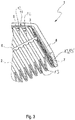
- FIG. 3 shows the enlarged edge of the air filter 1 in the region of its frontal fold blade 3, which is inserted for mechanical reinforcement of an end fold 13 'in selbige.
- the air filter 1 is now again shown in its final state ready for assembly, but the circumferential sealing strip is indicated only partially transparent for reasons of clarity.
- the specific height of the end-face fold sword 3, which remains only slightly behind that of the bellows 2 itself, in order to allow sufficient insertion into its end fold 13 'and to give the comb ring the desired compressive stiffness in the longitudinal direction L, is now clear.
- the enlarged partial view of the FIG. 3 can also recognize a perpendicular to the frontal fold blade 3 connected to this support strut 6, the low support teeth 12 alternate with narrow cutouts for clamping the filter medium and the frontal fold blade 3 thus support the recording in the longitudinal direction L occurring compressive forces.
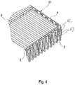
- FIG. 4 connects this support strut 6, the frontal fold sword 3 of FIG. 3 with a parallel cover-side pleat blade 4, whose along the sword 4 extending groove-shaped depression - increases the stiffness of the support frame in an advantageous manner - according to the operating principle of a reinforcing bead.
- the shape of the outer band 5 is the enlarged partial view according to FIG. 4 refer to.
- an alternating sequence of three respective lower support teeth 12 with a high support tooth 12 becomes clear, each support tooth 12 holding two adjacent folds 13 at a predetermined distance.
- each fold 13 serves a formed between two adjacent supporting teeth 12 concave cutout of the outer band 5, which is larger compared to the mentioned sections of the support strut to allow lateral displacement of the folds 13 within certain limits.
- a plurality between the outer band 5 and the folds 13 provided, in FIG. 4 unrecognizable joints connects the folds 13 still punctually with the outer band 5 and thus serves to secure its position.
- the safety function of the comb ring 11 is additionally by the in FIG. 5 shown circulating belt supports 7, the width of which falls below the fold height in favor of the weight saving recognizable.
- This additional reinforcement allows a particularly thin-walled design of the comb ring 11, for example in injection molding, with a wall thickness of less than 1.0 mm, but at least in the range below 1.5 mm, depending on the application proves to be sufficient.
- the desired low wall thickness may require injecting the liquefied, usually polymeric material at several positions in a corresponding injection mold to ensure its uniform distribution within the mold.
- Alternative embodiments may be used as a material, for example a cardboard or a suitable pressed material, without departing from the scope of the invention.
Landscapes
- Chemical & Material Sciences (AREA)
- Chemical Kinetics & Catalysis (AREA)
- Filtering Of Dispersed Particles In Gases (AREA)
- Air Filters, Heat-Exchange Apparatuses, And Housings Of Air-Conditioning Units (AREA)
- Air-Conditioning For Vehicles (AREA)
Description
- Die Erfindung betrifft ein Luftfilter, insbesondere ein Fahrgastraumfilter, nach dem Oberbegriff des Anspruchs 1.
- Als Luftfilter wird jedweder filternde Abscheider bezeichnet, der Aerosole oder andere unerwünschte Schwebstoffe wie Krankheitserreger, Pollen, Stäube oder Gase aus der Luft zu entfernen vermag. Als Filtermedium oder Kollektor eines gattungsgemäßen Luftfilters kommen typischerweise Fasern oder Körner zur Anwendung.
-
DE 101 11 318 A1 offenbart eine Filtervorrichtung zur Ausrüstung einer Belüftungs- und/oder Heizungs- und/oder Klimaanlage, insbesondere für Kraftfahrzeuge, die einen Rahmen umfasst, der ein biegsames und verformbares Filtermedium wenigstens teilweise umgibt: Der Rahmen besteht aus einem biegsamen und verformbaren thermoplastischen Elastomer und ist durch Aufformen am Filtermedium befestigt; er umfasst zwei Seitenwände mit geringer Dicke, deren Innenflächen mit Erhebungen versehen sind, die die Längsränder des Filtermediums umgeben. -
DE 198 16 238 A1 schlägt eine Versteifungsleiste für ein plattenförmiges Filterelement mit zickzackförmig gefaltetem Filterbahnmaterial vor, die bei einer Wölbbarkeit des Filterelementes für eine gegenseitige Lagefixierung der Falten sorgt. Diesem Zweck soll eine Versteifungsleiste mit folgenden Merkmalen dienen: Die Versteifungsleiste ist in der Form eines Kammes mit einem durchgehenden Längssteg und von diesem ausgehenden Zähnen ausgebildet; die Zähne des Kammes sind zur im Wesentlichen formschlüssigen Aufnahme der Falten des Filterbahnmaterials geeignet; voneinander beabstandete, aus benachbarten Zähnen bestehende Zahnpaare sind als Federklammern für ein kraftschlüssiges Einspannen jeweils einer Falte eines Filterbahnmaterials ausgebildet; der Längssteg der Versteifungsleiste ist in der von den Zähnen aufgespannten Längsebene elastisch biegsam, während er gegen seitliches Ausknicken erheblich biegesteifer ausgebildet ist. - Aus der
DE 39 36 858 A1 ist ein Luftfilter bekannt, der einen Faltenbalg mit einem gefalteten, luftdurchlässigen Filtermedium aufweist. Der Luftfilter weist ferner einen Kammring mit einer Vielzahl von Stützzähnen auf, die sämtlich identlisch ausgebildet sind. - Der Erfindung liegt die Aufgabe zugrunde, ein besonders leichtes Luftfilter zu schaffen.
- Diese Aufgabe wird durch ein Luftfilter mit den Merkmalen des Anspruchs 1 gelöst.
- Die Erfindung fußt demnach auf dem Grundgedanken, den umlaufenden Stützrahmen eines als Filterkörper fungierenden Faltenbalgs in Gestalt eines neuartigen multifunktionalen Bauteils auszuführen, dass im Folgenden wegen seiner zinkenartig aufragenden Stützzähne als "Kammring" bezeichnet werden soll. In ihrer Form und Anordnung entlang des umlaufenden Kammrings sind diese Stützzähne dabei solchermaßen konfiguriert, dass wenigstens ein Stützzahn, insbesondere in Längsrichtung benachbarte Stützzähne, zwei in der Längsrichtung des Faltenbalgs benachbarte Falten in einem vorgegebenen Abstand zu fixieren vermögen.
- Um die endseitigen Falten des Balgs mechanisch zu verstärken und insbesondere gegen ein mögliches Durchbiegen unter Belastung zu schützen, kann besagter Kammring zwei quer zu der Faltungsrichtung ausgerichtete Faltenschwerter umfassen, welche zu diesem Zweck in die gegenüberliegenden Endfalten eingesteckt werden. In einer solchen Ausführungsform bietet es sich ferner an, die beschriebenen Stützzähne entlang zweier die Faltenschwerter verbindender Außenbänder anzuordnen. Da bereits die erwähnten Faltenschwerter dem Kammring und somit dem gesamten Luftfilter eine gewisse Biegesteifigkeit in Längsrichtung des Faltenbalgs verleihen, erweist sich in diesem Fall eine biegeschlaffe Ausführung der Außenbänder als hinreichend, um den sicheren Halt sowie die Einhaltung des vorgegebenen Faltenabstands bei unterschiedlichsten Strömungsgeschwindigkeiten des zu filtrierenden Luftstroms zu gewährleisten. Eine gewisse Flexibilität der seitlich des Faltenbalgs verlaufenden Außenbänder mag sich insofern gar als vorteilhaft erweisen, da deren elastische Vorspannkraft ein optimales Anliegen des Kammrings an den Wandungen eines zur Aufnahme des Luftfilters vorgesehenen Montagegehäuses begünstigt und somit etwaigen Leckagen vorbeugt.
- Ein zielführender Kompromiss zwischen der angestrebten Gewichtseinsparung einerseits und der erforderlichen Fixation des Faltenbalgs andererseits wird dabei erfindungsgemäß erreicht, indem die Außenbänder des Kammrings eine alternierende Anordnung hoher und niedriger Stützzähne aufweisen. An äquidistanten Knotenpunkten entlang der Außenbänder, beispielsweise an jeder dritten, vierten oder fünften Falte des Balgs, kann in diesem Fall eine Fügestelle vorgesehen sein, um die Verbindung von Faltenbalg und Kammring dauerhaft zu sichern.
- Um zu diesem Zweck die molekularen oder atomaren Kräfte der beidseitigen Kontaktflächen zu nutzen, ist hinsichtlich der genannten Fügestellen insbesondere an eine stoffschlüssige Verbindung zwischen Falten und Stützzähnen zu denken, welcher beispielsweise eine Schweißtechnik gemäß DIN 8593-6:2003-09 die gewünschte Festigkeit verleiht. Als vergleichsweise wärmearme Fügetechnik, die Verzug, Abkühlspannungen oder Gefügeveränderungen seitens Faltenbalgs oder Kammrings vermeidet, kommt ferner das in DIN 8593-8:2003-09 normierte Kleben in Betracht.
- Empfehlenswert ist in letzterer Variante vor allem die Verwendung einer als Hotmelt bekannten Gruppe von Klebstoffen, welche in der Werkstoffkunde anwendungsspezifisch auch als Schmelzklebstoffe, Heißklebestoffe, Heißkleber oder Heißleime bezeichnet werden. Die geringe Viskosität eines gattungsgemäßen Hotmelts oberhalb seines Schmelzpunkts erlaubt in diesem Fall eine fertigungspraktisch unkomplizierte Benetzung des als Substrat fungierenden Kammrings, während die anschließende Abkühlung des Hotmelts eine dauerhafte Kohäsion einleitet.
- Zur Aufnahme etwaiger in Längsrichtung des Faltenbalgs auf das Luftfilter wirkender Druckkräfte bietet sich dessen Ergänzung um eine oder mehrere Stützstreben an, die die gegenüberliegenden Faltenschwerter gegeneinander stabilisieren und die strukturelle Integrität der Anordnung somit zusätzlich stärken. Wird auch eine solche Stützstrebe mit Stützzähnen versehen, wie sie bezüglich der Außenbänder bereits erläutert wurden, so gestattet sie zugleich eine verbesserte Fixation der Falten.
- Die Position der Falten kann schließlich mittels eines den Faltenbalg umschließenden Gurtbandes gesichert werden, wobei sich zu diesem Zweck eine hinter der Höhe des Faltenbalgs zurückbleibende Gurtbreite als hinreichend erweist. Verbleibende seitliche Öffnungen des Faltenbalgs lassen sich schließlich mithilfe eines umlaufenden Dichtbands verschließen, welches funktionsgemäß aus einem luftundurchlässigen Dichtmedium zu fertigen ist. Eine alternative Nutzung dieser Öffnungen als Abläufe für Kondenswasser erweist sich insofern zumeist als entbehrlich.
- Die beschriebene Ausgestaltung erlaubt es, den als Stützrahmen dienenden Kammring mit einer Wandstärke von weniger als 1,0 mm, zumindest aber weniger als 1,5 mm, auszuführen, ohne die Formstabilität des Luftfilters übermäßig zu gefährden. Eine solche Beschaffenheit lässt sich beispielsweise im Wege des Spritzgießens realisieren, mittels dessen nach dem Stand der Technik bereits Werkstücke im Gewichtsbereich von wenigen Zehntelgramm als herstellbar gelten.
- Weitere wichtige Merkmale und Vorteile der Erfindung ergeben sich aus den Unteransprüchen, aus den Zeichnungen und aus der zugehörigen Figurenbeschreibung anhand der Zeichnungen.
- Es versteht sich, dass die vorstehend genannten und die nachstehend noch zu erläuternden Merkmale nicht nur in der jeweils angegebenen Kombination, sondern auch in anderen Kombinationen oder in Alleinstellung verwendbar sind, ohne den Rahmen der vorliegenden Erfindung zu verlassen.
- Bevorzugte Ausführungsbeispiele der Erfindung sind in den Zeichnungen dargestellt und werden in der nachfolgenden Beschreibung näher erläutert, wobei sich gleiche Bezugszeichen auf gleiche oder ähnliche oder funktional gleiche Komponenten beziehen.
- Es zeigen, jeweils schematisch
- Fig. 1
- die perspektivische Ansicht eines Luftfilters gemäß einer Ausführungsform der Erfindung,
- Fig. 2
- eine
Figur 1 entsprechende Explosionsdarstellung des erfindungsgemäßen Luftfilters, - Fig. 3
- die vergrößerte Detaildarstellung des Luftfilters in einem ersten Randbereich,
- Fig. 4
- die vergrößerte Detaildarstellung des Luftfilters in einem zweiten Randbereich und
- Fig. 5
- eine
Figur 4 entsprechende Detaildarstellung des mittels eines Gurtbands gesicherten Luftfilters. - Die perspektivische Darstellung der
Figur 1 gibt ein erfindungsgemäßes Luftfilter 1 in seinem montagebereiten Endzustand wieder, welcher auf die korrespondierende Grundform eines inFigur 1 nicht gezeigten Montagegehäuses angepasst ist. Insofern erlaubt die sich in der vorgesehenen Montage-Richtung M verjüngende Form des Luftfilters 1 sowie dessen dem Betrachter abgewandte stirnseitige Anlagefläche 9 das Einschieben des Luftfilters 1 durch einen Verschlussdeckel des Gehäuses, bis die Anlagefläche 9 an der Stirnseite des Gehäuses formschlüssig anliegt. - In dieser Endlage ist das Luftfilter 1 bis zu seiner - parallel zur stirnseitigen Anlagefläche 9 auf der gemäß
Figur 1 dem Betrachter zugewandten Seite des Luftfilters 1 angeordneten - deckelseitigen Anlagefläche 10 in das Montagegehäuse eingeschoben, sodass der Verschlussdeckel vom Monteur hinter dem Luftfilter 1 geschlossen werden kann, während das in der Längsrichtung L weitgehend drucksteife Luftfilter 1 die durch das Schließen des Deckels ausgeübte Druckkraft aufnimmt. - Wie genau diese Drucksteifigkeit des Luftfilters 1 in seiner der Montage-Richtung M entsprechenden Längsrichtung L gemäß der erfindungsgemäßen Leichtbauweise zu realisieren ist, verdeutlicht die Explosionsdarstellung der
Figur 2 . Erkennbar ist nunmehr der in der Längsrichtung L gefaltete Faltenbalg 2, dessen Faltenkanten somit in der quer zur Längsrichtung L verlaufenden Querrichtung B orientiert sind. Besonderes Augenmerk kommt dabei dem skelettartigen Kammring 11 zu, welcher den Faltenbalg 2 im Wesentlichen vollständig umläuft und dessen Falten 13 mittels einer Vielzahl von Stützzähnen 12 in ihrer vorgesehenen Lage fixiert. - Ein den Faltenbalg 2 ebenfalls umlaufendes Gurtband 7, welches seinerseits von einem luftundurchlässigen Dichtband 8 eingeschlossen wird, sichert die gezeigte Baugruppe zusätzlich. Es versteht sich, dass eine alternative, in den Abbildungen nicht gezeigte Ausführungsform eines Luftfilters 1 um den Preis der zusätzlichen Lagesicherung beziehungsweise Abdichtung auf die Verwendung des Gurtbandes 7, des Dichtbandes 8 oder gar beider Bänder 7, 8 verzichten mag, ohne den Rahmen der Erfindung zu verlassen.
-
Figur 3 zeigt den vergrößerten Rand des Luftfilters 1 im Bereich seines stirnseitigen Faltenschwerts 3, welches zur mechanischen Verstärkung einer Endfalte 13' in selbige eingesteckt ist. Entsprechend der perspektivischen Ansicht derFigur 1 ist das Luftfilter 1 nunmehr abermals in seinem montagebereiten Endzustand dargestellt, wobei jedoch das umlaufende Dichtband aus Gründen der Übersichtlichkeit lediglich teiltransparent angedeutet wird. Deutlich wird nun die spezifische Höhe des stirnseitigen Faltenschwerts 3, welche nur knapp hinter jener des Faltenbalgs 2 selbst zurückbleibt, um ein ausreichendes Einführen in dessen Endfalte 13' zu erlauben und dem Kammring die gewünschte Drucksteifigkeit in Längsrichtung L zu verleihen. Die charakteristischen Ausnehmungen des stirnseitigen Faltenschwerts 3, welche nach dem Schema eines Fachwerks die tragende Struktur des Stützrahmens unberührt lassen, führen dabei zu einer beträchtlichen Material- und Gewichtseinsparung und erlauben dem Faltenschwert 3 zugleich eine gewisse Flexibilität und Anpassungsfähigkeit an Unebenheiten des aufnehmenden Gehäuses. - Die vergrößerte Teildarstellung der
Figur 3 lässt zudem eine senkrecht zum stirnseitigen Faltenschwert 3 mit diesem verbundene Stützstrebe 6 erkennen, dessen niedrige Stützzähne 12 sich mit engen Ausschnitten zum Festklemmen des Filtermediums abwechseln und das stirnseitige Faltenschwert 3 somit bei der Aufnahme in Längsrichtung L auftretender Druckkräfte unterstützen. - Wie der
Figur 4 zu entnehmen ist, verbindet diese Stützstrebe 6 das stirnseitige Faltenschwert 3 derFigur 3 mit einem parallel verlaufenden deckelseitigen Faltenschwert 4, dessen längs des Schwerts 4 verlaufende rinnenförmige Vertiefung - gemäß dem Wirkprinzip einer Verstärkungssicke - die Steifigkeit des Stützrahmens in vorteilhafter Weise erhöht. - Auch die Formgebung des Außenbands 5 ist der vergrößerten Teilansicht gemäß
Figur 4 zu entnehmen. Insofern wird eine alternierende Abfolge jeweils drei niedriger Stützzähne 12 mit einem hohen Stützzahn 12 deutlich, wobei jeder Stützzahn 12 zwei benachbarte Falten 13 in einem vorgegebenen Abstand hält. Zur Aufnahme jeder Falte 13 dient dabei ein zwischen zwei benachbarten Stützzähnen 12 gebildeter konkaver Ausschnitt des Außenbandes 5, der gegenüber den erwähnten Ausschnitten der Stützstrebe größer ausfällt, um eine seitliche Verschiebung der Falten 13 in gewissen Grenzen zu ermöglichen. Eine Vielzahl zwischen dem Außenband 5 und den Falten 13 vorgesehener, inFigur 4 nicht erkennbarer Fügestellen verbindet die Falten 13 dennoch punktuell mit dem Außenband 5 und dient so dessen Lagesicherung. - Die Sicherungsfunktion des Kammrings 11 wird zusätzlich durch das in
Figur 5 dargestellte umlaufende Gurtband 7 unterstützt, dessen Breite zugunsten der Gewichtseinsparung die Faltenhöhe erkennbar unterschreitet. Diese zusätzliche Verstärkung erlaubt eine besonders dünnwandige Ausführung des Kammrings 11 beispielsweise in Spritzgusstechnik, wobei sich eine Wandstärke von weniger als 1,0 mm, zumindest aber im Bereich unterhalb von 1,5 mm, anwendungsabhängig als ausreichend erweist. Die angestrebte geringe Wandstärke kann es dabei erfordern, den verflüssigten, in aller Regel polymeren Werkstoff an mehreren Positionen in ein entsprechendes Spritzgießwerkzeug einzuspritzen, um dessen gleichmäßige Verteilung innerhalb der Form zu gewährleisten. Alternative Ausführungsformen mögen sich als Werkstoff beispielsweise einer Kartonage oder eines geeigneten Pressguts bedienen, ohne den Rahmen der Erfindung zu verlassen.
Claims (8)
- Luftfilter (1), insbesondere Fahrgastraumfilter,- mit einem Faltenbalg (2) aus einem in einer Längsrichtung (L) gefalteten luftdurchlässigen Filtermedium zum Filtrieren von Luft und- mit einem den Faltenbalg (2) umlaufenden Stützrahmen zum Stützen des Faltenbalges (2),- wobei der Stützrahmen ein im Wesentlichen geschlossener Kammring (11) mit einer Vielzahl von Stützzähnen (12) ist, derart beschaffen, dass wenigstens zwei in Längsrichtung (L) benachbarte Stützzähne (12) zwei in der Längsrichtung (L) benachbarte Falten (13) des Faltenbalgs (2) in einem vorgegebenen Abstand fixieren,- wobei der Kammring (11) zwei in einer quer zu der Längsrichtung (L) verlaufenden Querrichtung (B) in jeweils eine Endfalte (13') des Faltenbalgs (2) eingesteckte Faltenschwerter (3, 4) und zwei die Faltenschwerter (3, 4) verbindende Außenbänder (5) umfasst, welche die Stützzähne (12) aufweisen,dadurch gekennzeichnet,
dass die Außenbänder (5) hohe Stützzähne (12) und niedrige Stützzähne (12) aufweisen. - Luftfilter nach Anspruch 1,
gekennzeichnet durch
eine Vielzahl von Fügestellen zwischen den Außenbändern (5) und den Falten (13), wobei die Außenbänder (5) an den Fügestellen vorzugsweise stoffschlüssig mit den Falten (13) verbunden, insbesondere verschweißt oder mittels eines Hotmelts verklebt sind. - Luftfilter nach Anspruch 1 oder 2,
gekennzeichnet durch
mindestens eine die Faltenschwerter (3, 4) verbindende, in der Längsrichtung (L) ausgerichtete Stützstrebe (6), welche weitere Stützzähne (12) aufweist. - Luftfilter nach einem der Ansprüche 1 bis 3,
gekennzeichnet durch
ein den Faltenbalg (2) umschließendes Gurtband (7) mit einer Breite, welche eine Faltenhöhe des Faltenbalgs (2) unterschreitet. - Luftfilter nach Anspruch 4,
gekennzeichnet durch
ein das Gurtband (7) umlaufendes Dichtband (8) aus einem luftundurchlässigen Dichtmedium zum Abdichten des Luftfilters (1). - Luftfilter nach Anspruch 5,
dadurch gekennzeichnet, dass
das Dichtband (8) eine stirnseitige Anlagefläche (9) und eine deckelseitige Anlagefläche (10) aufweist, sodass, wenn das Luftfilter (1) gemäß einer der Längsrichtung (L) entsprechenden Montage-Richtung (M) in einem Gehäuse mit einer Stirnplatte und einem Verschlussdeckel montiert wird, die stirnseitige Anlagefläche (9) an der Stirnseite und die deckelseitige Anlagefläche (10) an dem Verschlussdeckel anliegt. - Luftfilter nach einem der Ansprüche 1 bis 6,
dadurch gekennzeichnet, dass
der Kammring (11) eine Wandstärke von weniger als 1,5 mm, vorzugsweise weniger als 1,0 mm aufweist. - Luftfilter nach einem der Ansprüche 1 bis 7,
dadurch gekennzeichnet, dass
der Kammring (11) ein Thermoplast, eine Kartonage oder ein Pressgut enthält.
Applications Claiming Priority (2)
| Application Number | Priority Date | Filing Date | Title |
|---|---|---|---|
| DE102013218219.8A DE102013218219A1 (de) | 2013-09-11 | 2013-09-11 | Luftfilter |
| PCT/EP2014/069151 WO2015036386A1 (de) | 2013-09-11 | 2014-09-09 | Luftfilter |
Publications (2)
| Publication Number | Publication Date |
|---|---|
| EP3043883A1 EP3043883A1 (de) | 2016-07-20 |
| EP3043883B1 true EP3043883B1 (de) | 2017-07-19 |
Family
ID=51542341
Family Applications (1)
| Application Number | Title | Priority Date | Filing Date |
|---|---|---|---|
| EP14766422.1A Not-in-force EP3043883B1 (de) | 2013-09-11 | 2014-09-09 | Luftfilter |
Country Status (7)
| Country | Link |
|---|---|
| US (1) | US9630136B2 (de) |
| EP (1) | EP3043883B1 (de) |
| JP (1) | JP6085720B2 (de) |
| KR (1) | KR101753021B1 (de) |
| CN (1) | CN105517688B (de) |
| DE (1) | DE102013218219A1 (de) |
| WO (1) | WO2015036386A1 (de) |
Families Citing this family (7)
| Publication number | Priority date | Publication date | Assignee | Title |
|---|---|---|---|---|
| DE102015005565A1 (de) * | 2015-05-04 | 2016-11-10 | Mann + Hummel Gmbh | Verfahren zum Herstellen von Filterbälgen |
| US10350533B2 (en) | 2016-08-30 | 2019-07-16 | Filtereasy, Inc. | Folding air filter assembly and apparatus |
| DE102016015062A1 (de) * | 2016-12-19 | 2018-06-21 | Mann + Hummel Gmbh | Filterelement, insbesondere zur Gasfiltration |
| US10427079B2 (en) | 2018-02-28 | 2019-10-01 | Filtereasy, Inc. | Variable air filter assemblies |
| CN108454353A (zh) * | 2018-05-18 | 2018-08-28 | 重庆水神话科技有限公司 | 车用空气制水及空气净化装置 |
| DE102018119684A1 (de) * | 2018-08-14 | 2020-02-20 | Dürr Systems Ag | Filterstrukturkörper und Filtermodul zum Abscheiden von Verunreinigungen aus einem Rohfluidstrom |
| USD1103355S1 (en) * | 2024-05-09 | 2025-11-25 | Xiaohui Sun | Humidifier filter pad |
Family Cites Families (23)
| Publication number | Priority date | Publication date | Assignee | Title |
|---|---|---|---|---|
| US2135863A (en) * | 1937-07-09 | 1938-11-08 | Warren S Moore | Air filter |
| US4177050A (en) * | 1976-08-23 | 1979-12-04 | Farr Company | Air filter assembly |
| DE3529579A1 (de) * | 1985-08-17 | 1987-02-19 | Sueddeutsche Kuehler Behr | Staubfilter |
| JPH01101615U (de) * | 1987-12-28 | 1989-07-07 | ||
| DE3929759A1 (de) * | 1989-09-07 | 1991-03-21 | F & R Beteiligungs Gmbh | Anlage zur umweltfreundlichen umwandlung von mineralstoffhaltigen, nicht-regenerierbaren, gegebenenfalls hochkontaminierten altoelprodukten wechselnder zusammensetzung in verwertbare produkte |
| DE3936858A1 (de) * | 1989-11-06 | 1991-05-08 | Thermoplast Technik Ges Fuer K | Pollen- und staubfilter, verfahren zu seiner herstellung und montagehilfe zur durchfuehrung des verfahrens |
| US5273563A (en) * | 1992-12-24 | 1993-12-28 | Research Products Corp. | Filter media retaining assembly for an air filter |
| US5273564A (en) * | 1992-12-24 | 1993-12-28 | Research Products Corporation | One piece filter media framework |
| DE19524677A1 (de) * | 1994-07-07 | 1996-01-11 | Nippon Denso Co | Filtervorrichtung mit einem Filter |
| US5667545A (en) * | 1995-07-03 | 1997-09-16 | Toyoda Boshoku Corporation | Filter element for air cleaner and method of manufacturing the same |
| US5531892A (en) | 1995-09-15 | 1996-07-02 | Minnesota Mining And Manufacturing Company | Zigzag filter media and frame having triangular pleat stabilizing elements |
| US5711775A (en) * | 1996-04-15 | 1998-01-27 | Tennant Company | Sweeper with electromagnetic filter cleaning |
| US6074450A (en) * | 1996-10-15 | 2000-06-13 | Raber; Robert R. | Air filter assembly |
| DE19816238A1 (de) | 1998-04-11 | 1999-10-14 | Knecht Filterwerke Gmbh | Versteifungsleiste für ein Filterelement mit zick-zack-förmig gefaltetem Filterbahnmaterial |
| FR2806318B1 (fr) | 2000-03-15 | 2002-10-25 | Valeo | Dispositif de filtration destine a equiper un appareil d'aeration et/ou de chauffage et/ou de climatisation, notamment pour vehicule automobile |
| US6740136B2 (en) * | 2001-10-12 | 2004-05-25 | 3M Innovative Properties Company | Interconnected filter frame and filter framing method |
| US6723150B2 (en) * | 2002-02-28 | 2004-04-20 | American Standard International Inc. | Air filter with expandable filter media |
| KR200295354Y1 (ko) * | 2002-08-07 | 2002-11-18 | 정하익 | 필터 |
| US6986799B2 (en) * | 2002-08-21 | 2006-01-17 | Romanow Enterprises, Inc. | Recyclable air filter |
| US7004989B2 (en) * | 2003-08-22 | 2006-02-28 | Camfil Farr, Inc. | Filter assembly with compressed media edge seal |
| US8137427B2 (en) * | 2009-03-17 | 2012-03-20 | Mann & Hummel Gmbh | Filter element with pleat support combs |
| JP6263331B2 (ja) * | 2013-02-21 | 2018-01-17 | 株式会社Roki | フィルタエレメント |
| JP2015016435A (ja) * | 2013-07-11 | 2015-01-29 | キヤノン株式会社 | フィルタ組立体 |
-
2013
- 2013-09-11 DE DE102013218219.8A patent/DE102013218219A1/de not_active Withdrawn
-
2014
- 2014-09-09 EP EP14766422.1A patent/EP3043883B1/de not_active Not-in-force
- 2014-09-09 JP JP2016516503A patent/JP6085720B2/ja not_active Expired - Fee Related
- 2014-09-09 US US15/021,270 patent/US9630136B2/en not_active Expired - Fee Related
- 2014-09-09 CN CN201480048710.XA patent/CN105517688B/zh not_active Expired - Fee Related
- 2014-09-09 KR KR1020167007685A patent/KR101753021B1/ko not_active Expired - Fee Related
- 2014-09-09 WO PCT/EP2014/069151 patent/WO2015036386A1/de not_active Ceased
Also Published As
| Publication number | Publication date |
|---|---|
| JP6085720B2 (ja) | 2017-02-22 |
| US9630136B2 (en) | 2017-04-25 |
| JP2016531727A (ja) | 2016-10-13 |
| CN105517688A (zh) | 2016-04-20 |
| KR20160042137A (ko) | 2016-04-18 |
| EP3043883A1 (de) | 2016-07-20 |
| KR101753021B1 (ko) | 2017-06-30 |
| US20160220940A1 (en) | 2016-08-04 |
| DE102013218219A1 (de) | 2015-03-12 |
| WO2015036386A1 (de) | 2015-03-19 |
| CN105517688B (zh) | 2017-04-12 |
Similar Documents
| Publication | Publication Date | Title |
|---|---|---|
| EP3043883A1 (de) | Luftfilter | |
| EP2135662B1 (de) | Komprimierbares Filterelement mit zueinander geneigten Endklappen | |
| DE10013301B4 (de) | Filtereinsatz | |
| DE69225981T2 (de) | Filtersystem zum filtrieren von fluiden | |
| DE102015011339B4 (de) | Filterelement mit einer umlaufenden Dichtung und Verfahren zu seiner Herstellung | |
| EP3310454B1 (de) | Filterelement mit vorabscheider und filtersystem | |
| DE19534254A1 (de) | Filterelement | |
| WO2015075104A1 (de) | Filterelement mit filterbalg | |
| DE102008021225A1 (de) | Filtermodul für Sprühkabinen | |
| DE102015015778A1 (de) | Filterelement, Filter und Filtergehäuse eines Filters | |
| DE102017219009A1 (de) | Filterverbund zum Verbau in einem Fahrzeug | |
| EP2397211B1 (de) | Innenraumluftfilterelement, Filteraufnahme, Filteranordnung und Verfahren zum Herstellen des Innenraumluftfilterelements | |
| DE102016015062A1 (de) | Filterelement, insbesondere zur Gasfiltration | |
| DE102014016560A1 (de) | Innenraumfilter und Filteranordnung | |
| DE10241748B4 (de) | Filterelement | |
| WO2008119410A1 (de) | Filteranordnung | |
| DE102007057616A1 (de) | Filtereinsatz und Filtereinrichtung | |
| EP2868362B1 (de) | Filteranordnung | |
| EP1867378B1 (de) | Komprimierbares Filterelement | |
| DE102017000111A1 (de) | Filterelement mit Zusatzbauteil und Filtersystem | |
| EP1813341B1 (de) | Filterelement für einen Luftfilter | |
| DE102008033044B3 (de) | Komprimierbares Filterelement mit einsatzbarem Strömungskanal | |
| DE102016011451A1 (de) | Innenraumluftfilter, eine Filteranordnung und ein Verfahren zum Einbauen eines Innenraumluftfilters | |
| DE3028840C2 (de) | Kupplungsträgerkonstruktion für abwerfbare Lasten unter Flugzeugen | |
| EP4541447B1 (de) | Filter und filteranordnung |
Legal Events
| Date | Code | Title | Description |
|---|---|---|---|
| PUAI | Public reference made under article 153(3) epc to a published international application that has entered the european phase |
Free format text: ORIGINAL CODE: 0009012 |
|
| 17P | Request for examination filed |
Effective date: 20160304 |
|
| AK | Designated contracting states |
Kind code of ref document: A1 Designated state(s): AL AT BE BG CH CY CZ DE DK EE ES FI FR GB GR HR HU IE IS IT LI LT LU LV MC MK MT NL NO PL PT RO RS SE SI SK SM TR |
|
| AX | Request for extension of the european patent |
Extension state: BA ME |
|
| RIN1 | Information on inventor provided before grant (corrected) |
Inventor name: DRESSLER, BERND Inventor name: RHODE, FRANK Inventor name: VON MERKATZ, HENDRIK |
|
| DAX | Request for extension of the european patent (deleted) | ||
| GRAP | Despatch of communication of intention to grant a patent |
Free format text: ORIGINAL CODE: EPIDOSNIGR1 |
|
| INTG | Intention to grant announced |
Effective date: 20170228 |
|
| GRAS | Grant fee paid |
Free format text: ORIGINAL CODE: EPIDOSNIGR3 |
|
| GRAA | (expected) grant |
Free format text: ORIGINAL CODE: 0009210 |
|
| AK | Designated contracting states |
Kind code of ref document: B1 Designated state(s): AL AT BE BG CH CY CZ DE DK EE ES FI FR GB GR HR HU IE IS IT LI LT LU LV MC MK MT NL NO PL PT RO RS SE SI SK SM TR |
|
| REG | Reference to a national code |
Ref country code: GB Ref legal event code: FG4D Free format text: NOT ENGLISH |
|
| REG | Reference to a national code |
Ref country code: CH Ref legal event code: EP |
|
| REG | Reference to a national code |
Ref country code: IE Ref legal event code: FG4D Free format text: LANGUAGE OF EP DOCUMENT: GERMAN |
|
| REG | Reference to a national code |
Ref country code: AT Ref legal event code: REF Ref document number: 909837 Country of ref document: AT Kind code of ref document: T Effective date: 20170815 |
|
| REG | Reference to a national code |
Ref country code: DE Ref legal event code: R096 Ref document number: 502014004696 Country of ref document: DE |
|
| REG | Reference to a national code |
Ref country code: NL Ref legal event code: MP Effective date: 20170719 |
|
| REG | Reference to a national code |
Ref country code: LT Ref legal event code: MG4D |
|
| PG25 | Lapsed in a contracting state [announced via postgrant information from national office to epo] |
Ref country code: LT Free format text: LAPSE BECAUSE OF FAILURE TO SUBMIT A TRANSLATION OF THE DESCRIPTION OR TO PAY THE FEE WITHIN THE PRESCRIBED TIME-LIMIT Effective date: 20170719 Ref country code: SE Free format text: LAPSE BECAUSE OF FAILURE TO SUBMIT A TRANSLATION OF THE DESCRIPTION OR TO PAY THE FEE WITHIN THE PRESCRIBED TIME-LIMIT Effective date: 20170719 Ref country code: HR Free format text: LAPSE BECAUSE OF FAILURE TO SUBMIT A TRANSLATION OF THE DESCRIPTION OR TO PAY THE FEE WITHIN THE PRESCRIBED TIME-LIMIT Effective date: 20170719 Ref country code: FI Free format text: LAPSE BECAUSE OF FAILURE TO SUBMIT A TRANSLATION OF THE DESCRIPTION OR TO PAY THE FEE WITHIN THE PRESCRIBED TIME-LIMIT Effective date: 20170719 Ref country code: NO Free format text: LAPSE BECAUSE OF FAILURE TO SUBMIT A TRANSLATION OF THE DESCRIPTION OR TO PAY THE FEE WITHIN THE PRESCRIBED TIME-LIMIT Effective date: 20171019 Ref country code: NL Free format text: LAPSE BECAUSE OF FAILURE TO SUBMIT A TRANSLATION OF THE DESCRIPTION OR TO PAY THE FEE WITHIN THE PRESCRIBED TIME-LIMIT Effective date: 20170719 |
|
| PG25 | Lapsed in a contracting state [announced via postgrant information from national office to epo] |
Ref country code: PL Free format text: LAPSE BECAUSE OF FAILURE TO SUBMIT A TRANSLATION OF THE DESCRIPTION OR TO PAY THE FEE WITHIN THE PRESCRIBED TIME-LIMIT Effective date: 20170719 Ref country code: LV Free format text: LAPSE BECAUSE OF FAILURE TO SUBMIT A TRANSLATION OF THE DESCRIPTION OR TO PAY THE FEE WITHIN THE PRESCRIBED TIME-LIMIT Effective date: 20170719 Ref country code: RS Free format text: LAPSE BECAUSE OF FAILURE TO SUBMIT A TRANSLATION OF THE DESCRIPTION OR TO PAY THE FEE WITHIN THE PRESCRIBED TIME-LIMIT Effective date: 20170719 Ref country code: ES Free format text: LAPSE BECAUSE OF FAILURE TO SUBMIT A TRANSLATION OF THE DESCRIPTION OR TO PAY THE FEE WITHIN THE PRESCRIBED TIME-LIMIT Effective date: 20170719 Ref country code: GR Free format text: LAPSE BECAUSE OF FAILURE TO SUBMIT A TRANSLATION OF THE DESCRIPTION OR TO PAY THE FEE WITHIN THE PRESCRIBED TIME-LIMIT Effective date: 20171020 Ref country code: BG Free format text: LAPSE BECAUSE OF FAILURE TO SUBMIT A TRANSLATION OF THE DESCRIPTION OR TO PAY THE FEE WITHIN THE PRESCRIBED TIME-LIMIT Effective date: 20171019 Ref country code: IS Free format text: LAPSE BECAUSE OF FAILURE TO SUBMIT A TRANSLATION OF THE DESCRIPTION OR TO PAY THE FEE WITHIN THE PRESCRIBED TIME-LIMIT Effective date: 20171119 |
|
| REG | Reference to a national code |
Ref country code: DE Ref legal event code: R097 Ref document number: 502014004696 Country of ref document: DE |
|
| PG25 | Lapsed in a contracting state [announced via postgrant information from national office to epo] |
Ref country code: CZ Free format text: LAPSE BECAUSE OF FAILURE TO SUBMIT A TRANSLATION OF THE DESCRIPTION OR TO PAY THE FEE WITHIN THE PRESCRIBED TIME-LIMIT Effective date: 20170719 Ref country code: DK Free format text: LAPSE BECAUSE OF FAILURE TO SUBMIT A TRANSLATION OF THE DESCRIPTION OR TO PAY THE FEE WITHIN THE PRESCRIBED TIME-LIMIT Effective date: 20170719 Ref country code: RO Free format text: LAPSE BECAUSE OF FAILURE TO SUBMIT A TRANSLATION OF THE DESCRIPTION OR TO PAY THE FEE WITHIN THE PRESCRIBED TIME-LIMIT Effective date: 20170719 |
|
| REG | Reference to a national code |
Ref country code: CH Ref legal event code: PL |
|
| PLBE | No opposition filed within time limit |
Free format text: ORIGINAL CODE: 0009261 |
|
| STAA | Information on the status of an ep patent application or granted ep patent |
Free format text: STATUS: NO OPPOSITION FILED WITHIN TIME LIMIT |
|
| PG25 | Lapsed in a contracting state [announced via postgrant information from national office to epo] |
Ref country code: SK Free format text: LAPSE BECAUSE OF FAILURE TO SUBMIT A TRANSLATION OF THE DESCRIPTION OR TO PAY THE FEE WITHIN THE PRESCRIBED TIME-LIMIT Effective date: 20170719 Ref country code: MC Free format text: LAPSE BECAUSE OF FAILURE TO SUBMIT A TRANSLATION OF THE DESCRIPTION OR TO PAY THE FEE WITHIN THE PRESCRIBED TIME-LIMIT Effective date: 20170719 Ref country code: SM Free format text: LAPSE BECAUSE OF FAILURE TO SUBMIT A TRANSLATION OF THE DESCRIPTION OR TO PAY THE FEE WITHIN THE PRESCRIBED TIME-LIMIT Effective date: 20170719 Ref country code: EE Free format text: LAPSE BECAUSE OF FAILURE TO SUBMIT A TRANSLATION OF THE DESCRIPTION OR TO PAY THE FEE WITHIN THE PRESCRIBED TIME-LIMIT Effective date: 20170719 Ref country code: IT Free format text: LAPSE BECAUSE OF FAILURE TO SUBMIT A TRANSLATION OF THE DESCRIPTION OR TO PAY THE FEE WITHIN THE PRESCRIBED TIME-LIMIT Effective date: 20170719 |
|
| 26N | No opposition filed |
Effective date: 20180420 |
|
| REG | Reference to a national code |
Ref country code: IE Ref legal event code: MM4A |
|
| REG | Reference to a national code |
Ref country code: BE Ref legal event code: MM Effective date: 20170930 |
|
| PG25 | Lapsed in a contracting state [announced via postgrant information from national office to epo] |
Ref country code: LU Free format text: LAPSE BECAUSE OF NON-PAYMENT OF DUE FEES Effective date: 20170909 |
|
| REG | Reference to a national code |
Ref country code: FR Ref legal event code: ST Effective date: 20180531 |
|
| PG25 | Lapsed in a contracting state [announced via postgrant information from national office to epo] |
Ref country code: IE Free format text: LAPSE BECAUSE OF NON-PAYMENT OF DUE FEES Effective date: 20170909 Ref country code: CH Free format text: LAPSE BECAUSE OF NON-PAYMENT OF DUE FEES Effective date: 20170930 Ref country code: LI Free format text: LAPSE BECAUSE OF NON-PAYMENT OF DUE FEES Effective date: 20170930 |
|
| PG25 | Lapsed in a contracting state [announced via postgrant information from national office to epo] |
Ref country code: FR Free format text: LAPSE BECAUSE OF NON-PAYMENT OF DUE FEES Effective date: 20171002 Ref country code: SI Free format text: LAPSE BECAUSE OF FAILURE TO SUBMIT A TRANSLATION OF THE DESCRIPTION OR TO PAY THE FEE WITHIN THE PRESCRIBED TIME-LIMIT Effective date: 20170719 Ref country code: BE Free format text: LAPSE BECAUSE OF NON-PAYMENT OF DUE FEES Effective date: 20170930 |
|
| PG25 | Lapsed in a contracting state [announced via postgrant information from national office to epo] |
Ref country code: MT Free format text: LAPSE BECAUSE OF FAILURE TO SUBMIT A TRANSLATION OF THE DESCRIPTION OR TO PAY THE FEE WITHIN THE PRESCRIBED TIME-LIMIT Effective date: 20170719 |
|
| PGFP | Annual fee paid to national office [announced via postgrant information from national office to epo] |
Ref country code: DE Payment date: 20181130 Year of fee payment: 5 |
|
| GBPC | Gb: european patent ceased through non-payment of renewal fee |
Effective date: 20180909 |
|
| PG25 | Lapsed in a contracting state [announced via postgrant information from national office to epo] |
Ref country code: HU Free format text: LAPSE BECAUSE OF FAILURE TO SUBMIT A TRANSLATION OF THE DESCRIPTION OR TO PAY THE FEE WITHIN THE PRESCRIBED TIME-LIMIT; INVALID AB INITIO Effective date: 20140909 |
|
| PG25 | Lapsed in a contracting state [announced via postgrant information from national office to epo] |
Ref country code: GB Free format text: LAPSE BECAUSE OF NON-PAYMENT OF DUE FEES Effective date: 20180909 Ref country code: CY Free format text: LAPSE BECAUSE OF FAILURE TO SUBMIT A TRANSLATION OF THE DESCRIPTION OR TO PAY THE FEE WITHIN THE PRESCRIBED TIME-LIMIT Effective date: 20170719 |
|
| PG25 | Lapsed in a contracting state [announced via postgrant information from national office to epo] |
Ref country code: MK Free format text: LAPSE BECAUSE OF FAILURE TO SUBMIT A TRANSLATION OF THE DESCRIPTION OR TO PAY THE FEE WITHIN THE PRESCRIBED TIME-LIMIT Effective date: 20170719 |
|
| PG25 | Lapsed in a contracting state [announced via postgrant information from national office to epo] |
Ref country code: TR Free format text: LAPSE BECAUSE OF FAILURE TO SUBMIT A TRANSLATION OF THE DESCRIPTION OR TO PAY THE FEE WITHIN THE PRESCRIBED TIME-LIMIT Effective date: 20170719 |
|
| REG | Reference to a national code |
Ref country code: DE Ref legal event code: R119 Ref document number: 502014004696 Country of ref document: DE |
|
| PG25 | Lapsed in a contracting state [announced via postgrant information from national office to epo] |
Ref country code: PT Free format text: LAPSE BECAUSE OF FAILURE TO SUBMIT A TRANSLATION OF THE DESCRIPTION OR TO PAY THE FEE WITHIN THE PRESCRIBED TIME-LIMIT Effective date: 20170719 |
|
| PG25 | Lapsed in a contracting state [announced via postgrant information from national office to epo] |
Ref country code: AL Free format text: LAPSE BECAUSE OF FAILURE TO SUBMIT A TRANSLATION OF THE DESCRIPTION OR TO PAY THE FEE WITHIN THE PRESCRIBED TIME-LIMIT Effective date: 20170719 Ref country code: DE Free format text: LAPSE BECAUSE OF NON-PAYMENT OF DUE FEES Effective date: 20200401 |
|
| REG | Reference to a national code |
Ref country code: AT Ref legal event code: MM01 Ref document number: 909837 Country of ref document: AT Kind code of ref document: T Effective date: 20190909 |
|
| PG25 | Lapsed in a contracting state [announced via postgrant information from national office to epo] |
Ref country code: AT Free format text: LAPSE BECAUSE OF NON-PAYMENT OF DUE FEES Effective date: 20190909 |