EP3043230B1 - Betriebsvorrichtung zur krafterfassung - Google Patents
Betriebsvorrichtung zur krafterfassung Download PDFInfo
- Publication number
- EP3043230B1 EP3043230B1 EP14843128.1A EP14843128A EP3043230B1 EP 3043230 B1 EP3043230 B1 EP 3043230B1 EP 14843128 A EP14843128 A EP 14843128A EP 3043230 B1 EP3043230 B1 EP 3043230B1
- Authority
- EP
- European Patent Office
- Prior art keywords
- section
- magnetic pole
- pole section
- rotor
- force
- Prior art date
- Legal status (The legal status is an assumption and is not a legal conclusion. Google has not performed a legal analysis and makes no representation as to the accuracy of the status listed.)
- Active
Links
Images







Classifications
-
- G—PHYSICS
- G05—CONTROLLING; REGULATING
- G05G—CONTROL DEVICES OR SYSTEMS INSOFAR AS CHARACTERISED BY MECHANICAL FEATURES ONLY
- G05G5/00—Means for preventing, limiting or returning the movements of parts of a control mechanism, e.g. locking controlling member
- G05G5/03—Means for enhancing the operator's awareness of arrival of the controlling member at a command or datum position; Providing feel, e.g. means for creating a counterforce
-
- G—PHYSICS
- G05—CONTROLLING; REGULATING
- G05G—CONTROL DEVICES OR SYSTEMS INSOFAR AS CHARACTERISED BY MECHANICAL FEATURES ONLY
- G05G1/00—Controlling members, e.g. knobs or handles; Assemblies or arrangements thereof; Indicating position of controlling members
- G05G1/04—Controlling members for hand actuation by pivoting movement, e.g. levers
Definitions
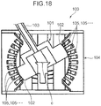
- each stator 105 constructs a magnetic pole on the side of the stationary section 104.
- a magnetic attraction force acts on the magnetic pole (permanent magnet) 102 of the rotating section 101.
- a torque around the center point c created at the rotating section 101 by the magnetic attraction force is used as a force sense that is perceived by an operator or the like when operating the operation lever 103.
- an expensive magnet such as a neodymium magnet is used as the permanent magnet 102 in order to obtain a large force sense (torque). This results in significantly high cost.
- demagnetization of the permanent magnet 102 may occur when an overcurrent is supplied to the excitation coil 106 at short-time rating or the like to form a strong magnetic field.
- the excitation coil 106 is heated by an overcurrent flowing through the excitation coil 106 or when the operation device 100 is used in a high-temperature atmosphere, the permanent magnet 102 is exposed to high temperature and, consequently, demagnetization or neutralization of the permanent magnet 102 may occur.
- a force-sense-imparting operation device (hereinafter, also simply referred to as an "operation device”) is a device for operating a working machine or the like.
- the operation device performs force sense presentation to an operator or the like through an operation member such as an operation lever when the operator or the like is operating the operation member.
- an operation member such as an operation lever when the operator or the like is operating the operation member.
- the operation device according to the present embodiment is used for a hoisting operation by a crane or the like.
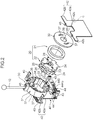
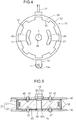
- each large diameter section 24 a plurality of protruded sections 26 that protrude outward in the radial direction are arranged at equal intervals in the circumferential direction. Moreover, each protruded section 26 corresponds to a site between adjacent notches 25. A tip surface 27 of each protruded section 26 is positioned on a common circle centered on the rotational axis C when viewed in the direction of the rotational axis C. The number of protruded sections 26 is the same in the respective large diameter sections 24. Corresponding protruded sections 26 in the pair of large diameter sections 24 oppose each other (are arranged) in the direction of the rotational axis C. Each large diameter section 24 in the present embodiment is provided with, for example, eight protruded sections 26.
- the rotor main body 33 encircles the stator section 20 in a circumferential direction at an outer side of the stator section 20 in a state where a clearance is provided in a radial direction of the shaft section 23 with respect to the stator section 20.
- the rotor main body 33 according to the present embodiment has a cylindrical shape.
- the rotor main body 33 according to the present embodiment has a length dimension in the direction of the rotational axis C that is approximately the same as a length dimension of the stator section 20 in the direction of the rotational axis C.
- Each of the pair of supporting plates 42 is a plate-like member that spreads in a direction perpendicular to the rotational axis C.
- the pair of supporting plates 42 is erected parallel to each other across a clearance in the direction of the rotational axis C which enables the stator section 20 and the rotor section 30 to be positioned between the pair of supporting plates 42.
- the supporting plate 42 according to the present embodiment includes a main body section 42a and extending sections 42b.
- the main body section 42a forms an approximately rectangular shape when viewed in the direction of the rotational axis C.
- the extending sections 42b extend outward from both sides of an upper end portion of the main body section 42a in a horizontal direction along an upper edge of the main body section 42a.
- a notch 42c depressed downward so as to avoid the rotational axis C and a periphery thereof is respectively provided at a center position in a direction along the upper edge of the main body section 42a of the upper end portion of each main body section 42a
- the pressing section 445 is a plate-like site that spreads in a direction perpendicular to the axial direction of the guide member 441 at the center of the lower portion of the returning section main body 442.
- the two guide members 441 penetrate a center portion of the pressing section 445.
- one compression coil spring 444a is compressed in accordance with a distance of the movement of the returning section main body 442 and biases the pressing section 445 toward center by a resilient force attributable to the compression. In other words, one compression coil spring 444a biases the pressing section 445 toward the neutral position.
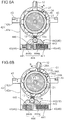
- a magnetic attraction force received by the rotor-side magnetic pole section 34A from a stator-side magnetic pole section 28B that is adjacent to the stator-side magnetic pole section 28A corresponding to the rotor-side magnetic pole section 34A is reliably smaller than a magnetic attraction force received by the rotor-side magnetic pole section 34A from the stator-side magnetic pole section 28A corresponding to the rotor-side magnetic pole section 34A.
- the operation device 10 is capable of reliably preventing the occurrence of cogging.
- the stator-side magnetic pole section 28A corresponding to the rotor-side magnetic pole section 34A refers to the stator-side magnetic pole section 28A that opposes the rotor-side magnetic pole section 34A in the radial direction.
- the greater the load during turning of a crane due to a factor such as a heavy load being hoisted by the crane the greater the excitation current supplied to the excitation coil 21. Therefore, the greater the degree by which the operation lever is tilted and the greater the turning load of the crane, the greater the torque created at the rotor section 30. Accordingly, it becomes difficult to extensively tilt the operation lever 12 in one operation. As a result, danger caused by a sudden turn of the crane can be prevented.
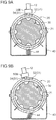
- stator-side magnetic pole sections 280 are arranged at equal intervals in a circumferential direction on a peripheral edge portion of a surface of the stator section 20 that opposes the rotor section 30. Each stator-side magnetic pole section 280 extends toward the rotor section 30. A groove 282 in which the excitation coil 21 is to be arranged is formed in each stator-side magnetic pole section 280 at a center portion of the stator-side magnetic pole section 280 in the direction of the rotational axis C. The number of the stator-side magnetic pole sections 280 is the same as the number of the rotor-side magnetic pole sections 340.
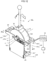
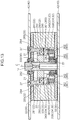
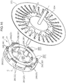
- FIG. 12 to 14 A further modification of an operation device utilizing the drive principle of an axial gap-type switched reluctance motor is shown in Figs. 12 to 14 .
- one of the stationary section and the rotating section has an excitation coil and at least one first magnetic pole section at which magnetic flux lines concentrate when the first magnetic pole section is excited by the excitation coil
- the other of the stationary section and the rotating section has at least one second magnetic pole section which is capable of opposition to the first magnetic pole section in a specific opposing direction
- the excitation coil has an opposing site which opposes the second magnetic pole section
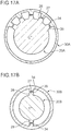
- the first magnetic pole section has a shape which encircles the excitation coil with the exception of the opposing site in a cross section perpendicular to a direction of flow of an excitation current in the excitation coil
- the second magnetic pole section has a shape which forms clearances in the opposing direction between the second magnetic pole section and each of the excitation coil and the first magnetic pole section when the second magnetic pole section opposes the first magnetic pole section and which forms a magnetic circuit in cooperation with the first magnetic pole section due to the second magnetic pole section being excited by the excitation coil in a state where the second magnetic pole section opposes the first magnetic pole section, the
- magnetoresistance between the first and second magnetic pole sections increases or decreases.
- a magnetic attraction force can be applied to the rotating section in a rotational direction.
- a torque can be created at the rotating section. Therefore, a force sense can be imparted to the operation member for rotationally operating the rotating section without using a permanent magnet. Details are as described below.
- the at least one first magnetic pole section includes a plurality of first magnetic pole sections which are provided at a plurality of positions arranged at intervals in a rotational direction of the rotating section
- the at least one second magnetic pole section includes a plurality of second magnetic pole sections which are provided at the same number of positions as the first magnetic pole sections arranged at intervals in the rotational direction, and each interval between the second magnetic pole sections mutually adjacent in the rotational direction is set so that, when one of the second magnetic pole sections opposes the first magnetic pole section corresponding thereto, the remaining second magnetic pole sections oppose corresponding first magnetic pole sections, respectively.
- the specific opposing direction may correspond to a direction of a rotational axis of the rotating section
- the first magnetic pole section and the second magnetic pole section may be provided so as to be relatively displaceable from each other in the direction of the rotational axis
- the force-sense-imparting operation device may further include a clearance maintaining mechanism which maintains a constant clearance between the first magnetic pole section and the second magnetic pole section in the direction of the rotational axis.
- the force-sense-imparting operation device may include: a rotation angle detecting section which detects a rotation angle of the rotating section; and a control section which adjusts an excitation current to be supplied to the excitation coil based on a result of detection by the rotation angle detecting section.
- a magnitude of a force sense imparted to the operation member can be adjusted by adjusting a magnitude of a torque created at the rotating section in accordance with a rotational operation (amount of rotation) of the rotating section by the operation member.
Landscapes
- Physics & Mathematics (AREA)
- General Physics & Mathematics (AREA)
- Engineering & Computer Science (AREA)
- Automation & Control Theory (AREA)
- Mechanical Control Devices (AREA)
- Electromagnets (AREA)
- Arrangement Or Mounting Of Control Devices For Change-Speed Gearing (AREA)
Claims (12)
- Kraftsensorisch wirkende Betätigungsvorrichtung (10), die ein Kraftgefühl unter Verwendung eines durch eine Magnetkraft erzeugten Drehmoments erzeugt, wobei die kraftsensorisch wirkende Betätigungsvorrichtung (10) Folgendes aufweist:einen stationären Abschnitt (20);einen Drehabschnitt (30), der in Bezug auf den stationären Abschnitt (20) drehbar ist; undein Betätigungselement (12) zum drehbaren Betätigen des Drehabschnitts (30), wobeinur einer von dem stationären Abschnitt (20) und dem Drehabschnitt (30) eine Erregerspule (21) und mindestens einen ersten Magnetpolabschnitt (28) aufweist, an dem sich magnetische Flusslinien konzentrieren, wenn der erste Magnetpolabschnitt (28) durch die Erregerspule (21) erregt wird,,der andere von dem stationären Abschnitt (20) und dem Drehabschnitt (30) mindestens einen zweiten Magnetpolabschnitt (34) aufweist, der dem ersten Magnetpolabschnitt (28) in einer spezifischen Gegenrichtung gegenüberliegen kann,die Erregerspule (21) eine Gegenseite aufweist, die dem zweiten Magnetpolabschnitt (34) gegenüberliegt, undder erste Magnetpolabschnitt (28) eine Form aufweist, die die Erregerspule (21) mit Ausnahme der Gegenseite in einem Querschnitt senkrecht zu einer Strömungsrichtung eines Erregerstroms in der Erregerspule (21) umschließt, unddadurch gekennzeichnet, dassder zweite Magnetpolabschnitt (34) eine Form aufweist, die Abstände in der Gegenrichtung zwischen dem zweiten Magnetpolabschnitt (34) und jedem von der Erregerspule (21) und dem ersten Magnetpolabschnitt (28) bildet, wenn der zweite Magnetpolabschnitt (34) dem ersten Magnetpolabschnitt (28) gegenüberliegt, und die in Zusammenarbeit mit dem ersten Magnetpolabschnitt (28) einen Magnetkreis bildet, da der zweite Magnetpolabschnitt (34) von der Erregerspule (21) in einem Zustand erregt wird, in welchem der zweite Magnetpolabschnitt (34) dem ersten Magnetpolabschnitt (28) gegenüberliegt, der Magnetkreis einen Umfang der Erregerspule (21) auf dem Querschnitt umgibt, wobei der zweite Magnetpolabschnitt (34) so angeordnet ist, dass er sich vom ersten Magnetpolabschnitt (28) durch Drehung des Drehabschnitts (30) trennt.
- Kraftsensorisch wirkende Betätigungsvorrichtung (10) nach Anspruch 1, wobeidie Erregerspule (21) und der erste Magnetpolabschnitt (28) an dem stationären Abschnitt (20) vorgesehen sind, undder zweite Magnetpolabschnitt (34) an dem Drehabschnitt (30) vorgesehen ist.
- Kraftsensorisch wirkende Betätigungsvorrichtung (10) nach Anspruch 1 oder 2, wobeider mindestens eine erste Magnetpolabschnitt (28) eine Vielzahl von ersten Magnetpolabschnitten (28) aufweist, die an einer Vielzahl von Positionen vorgesehen sind, die in Abständen in einer Drehrichtung des Drehabschnitts (30) angeordnet sind,der mindestens eine zweite Magnetpolabschnitt (34) eine Vielzahl von zweiten Magnetpolabschnitten (34) aufweist, die in der gleichen Anzahl von Positionen wie die ersten Magnetpolabschnitte (28) vorgesehen sind, die in Abständen in Drehrichtung angeordnet sind, undjeder Abstand zwischen den zweiten Magnetpolabschnitten (34), die in Drehrichtung aneinander angrenzen, so eingestellt ist, dass, wenn einer der zweiten Magnetpolabschnitte (34) dem ersten Magnetpolabschnitt (28), der diesem entspricht, gegenüberliegt, die verbleibenden zweiten Magnetpolabschnitte (34) den entsprechenden ersten Magnetpolabschnitten (28) gegenüberliegen.
- Kraftsensorisch wirkende Betätigungsvorrichtung (10) nach Anspruch 3, ferner miteinem Drehwinkelbegrenzungsabschnitt (51), der einen Drehwinkel des Drehbereichs (30) innerhalb eines vorgegebenen Winkelbereichs begrenzt, wobeider vorgeschriebene Winkelbereich ein solcher Winkelbereich ist, dass eine magnetische Anziehungskraft, die der zweite Magnetpolabschnitt (34) von dem ersten Magnetpolabschnitt (28) angrenzend an den ersten Magnetpolabschnitt (28) empfängt, der dem zweiten Magnetpolabschnitt (34) entspricht, kleiner ist als eine magnetische Anziehungskraft, die der zweite Magnetpolabschnitt (34) von dem entsprechenden ersten Magnetpolabschnitt (28) empfängt.
- Kraftsensorisch wirkende Betätigungsvorrichtung (10) nach einem der Ansprüche 1 bis 4, wobei
die spezifische Gegenrichtung eine radiale Richtung eines Kreises entlang einer Drehrichtung des Drehabschnitts (30) ist. - Kraftsensorisch wirkende Betätigungsvorrichtung (10) nach Anspruch 5, wobeider Drehabschnitt (30) den stationären Abschnitt (20) in Drehrichtung an einer Außenseite des stationären Abschnitts (20) in radialer Richtung umgibt, unddas Betätigungselement (12) an einer äußeren Umfangsfläche des Drehabschnitts (30) befestigt ist.
- Kraftsensorisch wirkende Betätigungsvorrichtung (10) nach einem der Ansprüche 1 bis 4, wobeidie spezifische Gegenrichtung eine Richtung einer Drehachse des Drehabschnitts (30) ist,der erste Magnetpolabschnitt (28) und der zweite Magnetpolabschnitt (34) so vorgesehen sind, dass sie in Richtung der Drehachse relativ zueinander verschiebbar sind, unddie kraftsensorisch wirkende Betätigungsvorrichtung (10) ferner einen Abstandshaltemechanismus (360) umfasst, der einen konstanten Abstand zwischen dem ersten Magnetpolabschnitt (28) und dem zweiten Magnetpolabschnitt (34) in Richtung der Drehachse aufrechterhält.
- Kraftsensorisch wirkende Betätigungsvorrichtung (10) nach Anspruch 7, wobei
der Abstandshaltemechanismus (360) Folgendes aufweist: eine nicht-magnetische Schicht (361), die zwischen dem ersten Magnetpolabschnitt (28) und dem zweiten Magnetpolabschnitt (34) in Richtung der Drehachse angeordnet ist; und ein Vorspannelement (362), das in Richtung der Drehachse elastisch verformbar ist und einen der ersten Magnetpolabschnitte (28) und den zweiten Magnetpolabschnitt (34) in Richtung des anderen Magnetpolabschnitts vorspannt, so dass ein Zustand aufrechterhalten wird, in dem die nicht-magnetische Schicht (361) zwischen dem ersten Magnetpolabschnitt (28) und dem zweiten Magnetpolabschnitt (34) liegt. - Kraftsensorisch wirkende Betätigungsvorrichtung (10) nach Anspruch 8, wobei
die nicht-magnetische Schicht (361) einen niedrigeren Reibungskoeffizienten aufweist als die Reibungskoeffizienten des ersten Magnetpolabschnitts (28) und des zweiten Magnetpolabschnitts (34). - Kraftsensorisch wirkende Betätigungsvorrichtung (10) nach einem der Ansprüche 1 bis 9, miteinem Drehwinkelerfassungsabschnitt (14), der einen Drehwinkel des Drehbereichs (30) erfasst; undeinem Steuerabschnitt (16), der einen der Erregerspule (21) zuzuführenden Erregerstrom basierend auf einem Ergebnis der Erfassung durch den Drehwinkelerfassungsabschnitt (14) einstellt.
- Kraftsensorisch wirkende Betätigungsvorrichtung (10) nach Anspruch 10, wobei
der Drehwinkelerfassungsabschnitt (14) an dem Drehabschnitt (30) befestigt ist. - Kraftsensorisch wirkende Betätigungsvorrichtung (10) nach Anspruch 10 oder 11, ferner miteinem Lasterfassungsabschnitt (16), der eine Last auf einen betätigten Abschnitt einer Arbeitsmaschine erfasst, die von der kraftsensorisch wirkenden Betätigungsvorrichtung (10) betätigt wird, wobeider Steuerabschnitt (16) betriebsfähig ist, um einen der Erregerspule (21) zuzuführenden Erregerstrom basierend auf einem Ergebnis der Erfassung durch den Lasterfassungsabschnitt (16) einzustellen.
Applications Claiming Priority (3)
| Application Number | Priority Date | Filing Date | Title |
|---|---|---|---|
| JP2013185244 | 2013-09-06 | ||
| JP2014091978A JP6325881B2 (ja) | 2013-09-06 | 2014-04-25 | 力覚付与型操作装置 |
| PCT/JP2014/072091 WO2015033807A1 (ja) | 2013-09-06 | 2014-08-25 | 力覚付与型操作装置 |
Publications (3)
| Publication Number | Publication Date |
|---|---|
| EP3043230A1 EP3043230A1 (de) | 2016-07-13 |
| EP3043230A4 EP3043230A4 (de) | 2017-08-23 |
| EP3043230B1 true EP3043230B1 (de) | 2019-12-04 |
Family
ID=52628285
Family Applications (1)
| Application Number | Title | Priority Date | Filing Date |
|---|---|---|---|
| EP14843128.1A Active EP3043230B1 (de) | 2013-09-06 | 2014-08-25 | Betriebsvorrichtung zur krafterfassung |
Country Status (5)
| Country | Link |
|---|---|
| US (1) | US10386883B2 (de) |
| EP (1) | EP3043230B1 (de) |
| JP (1) | JP6325881B2 (de) |
| CN (1) | CN105518565B (de) |
| WO (1) | WO2015033807A1 (de) |
Families Citing this family (7)
| Publication number | Priority date | Publication date | Assignee | Title |
|---|---|---|---|---|
| ITUB20169930A1 (it) * | 2016-01-12 | 2017-07-12 | Atk Race Srl | Talloniera con alza tacco per la pratica dello sci alpinismo |
| USD781191S1 (en) * | 2016-01-21 | 2017-03-14 | Pilot, Inc. | Shift knob cover |
| JP6878178B2 (ja) * | 2017-07-06 | 2021-05-26 | 株式会社神戸製鋼所 | 力覚付与型操作装置 |
| JP6868517B2 (ja) * | 2017-09-20 | 2021-05-12 | 株式会社神戸製鋼所 | 力覚付与型操作装置 |
| JP7026569B2 (ja) * | 2018-05-11 | 2022-02-28 | 株式会社神戸製鋼所 | 力覚付与型操作装置 |
| JP2020004149A (ja) * | 2018-06-29 | 2020-01-09 | パナソニックIpマネジメント株式会社 | 操作装置及び入力装置 |
| CN113632040B (zh) * | 2019-01-31 | 2023-09-29 | 雷蛇(亚太)私人有限公司 | 感应式操纵杆 |
Family Cites Families (12)
| Publication number | Priority date | Publication date | Assignee | Title |
|---|---|---|---|---|
| US4719381A (en) | 1985-08-21 | 1988-01-12 | The Curators Of The University Of Missouri | Electrical machines and apparatus for rotation around multiple axes |
| JPH01115051U (de) * | 1988-01-29 | 1989-08-02 | ||
| JP2000505922A (ja) * | 1996-12-11 | 2000-05-16 | アーベー・エレクトロニーク・ゲー・エム・ベー・ハー | ラッチ式切替機構 |
| DE19651315A1 (de) | 1996-12-11 | 1998-06-18 | A B Elektronik Gmbh | Rastschaltwerk |
| US6664666B2 (en) | 1998-12-23 | 2003-12-16 | Engineering Matters, Inc. | Motor assembly allowing output in multiple degrees of freedom |
| DE10029191A1 (de) | 2000-06-19 | 2001-12-20 | Philips Corp Intellectual Pty | Elektronisch gesteuerter Flüssigkeitsdrehknopf als haptisches Bedienelement |
| FR2943316B1 (fr) * | 2009-03-18 | 2012-09-14 | Airbus France | Procede d'uniformisation de la commande de poussee des moteurs d'un aeronef |
| JP5581179B2 (ja) | 2010-11-09 | 2014-08-27 | 株式会社神戸製鋼所 | Dcブラシレスモータおよびその制御方法 |
| JP2012195150A (ja) * | 2011-03-16 | 2012-10-11 | Canon Inc | 回転型スイッチ及び電子機器 |
| CN102510241B (zh) | 2011-11-15 | 2015-02-11 | 陈奚平 | 一种磁动力机械 |
| JP5792089B2 (ja) | 2012-02-08 | 2015-10-07 | アルプス電気株式会社 | 電磁ブレーキ装置及びこれを用いた力覚付与型回転入力装置 |
| JP2013175028A (ja) * | 2012-02-24 | 2013-09-05 | Alps Electric Co Ltd | 操作感触付与型入力装置 |
-
2014
- 2014-04-25 JP JP2014091978A patent/JP6325881B2/ja active Active
- 2014-08-25 US US14/916,030 patent/US10386883B2/en active Active
- 2014-08-25 WO PCT/JP2014/072091 patent/WO2015033807A1/ja not_active Ceased
- 2014-08-25 CN CN201480048944.4A patent/CN105518565B/zh not_active Expired - Fee Related
- 2014-08-25 EP EP14843128.1A patent/EP3043230B1/de active Active
Non-Patent Citations (1)
| Title |
|---|
| None * |
Also Published As
| Publication number | Publication date |
|---|---|
| CN105518565B (zh) | 2017-09-29 |
| JP2015072669A (ja) | 2015-04-16 |
| CN105518565A (zh) | 2016-04-20 |
| US20160216726A1 (en) | 2016-07-28 |
| JP6325881B2 (ja) | 2018-05-16 |
| EP3043230A4 (de) | 2017-08-23 |
| US10386883B2 (en) | 2019-08-20 |
| EP3043230A1 (de) | 2016-07-13 |
| WO2015033807A1 (ja) | 2015-03-12 |
Similar Documents
| Publication | Publication Date | Title |
|---|---|---|
| US10386883B2 (en) | Force-sense-imparting operation device | |
| CN102714443B (zh) | 旋转单相电磁执行机构 | |
| US10260873B2 (en) | Surveying apparatus with positioning device | |
| JP6016273B2 (ja) | ロータリーアクチュエータ及びそれを用いた操作感触付与型入力装置 | |
| JP2014121264A (ja) | リニアアクチェータ | |
| JP2014212686A (ja) | ステッピングモータ | |
| CN110323919A (zh) | 一种基于正应力电磁驱动的微定位装置 | |
| KR101434091B1 (ko) | 영구 자석형 회전 전기 | |
| EP2590004A1 (de) | Linsenantriebseinheit und Linsenvorrichtung und Bildaufnahmevorrichtung damit | |
| JP4594352B2 (ja) | 光学装置 | |
| US8084913B2 (en) | DC motor with asymmetrical poles | |
| CN104919687A (zh) | 具有减少齿槽磁滞的磁性制动器 | |
| JP6041437B2 (ja) | ロータリーアクチュエータ | |
| JP2013005491A (ja) | リニアアクチュエータ | |
| JP2012100407A (ja) | リニアアクチュエータ | |
| JP2013121275A (ja) | リニアアクチュエータ | |
| JP2019146422A (ja) | 可変界磁モータ | |
| JP6340219B2 (ja) | リニアモータ | |
| JP2012105432A (ja) | 球面モータ | |
| JP7482480B2 (ja) | 筒型リニアモータ | |
| JP6110165B2 (ja) | リニアモータ | |
| JP2016052181A (ja) | ブラシレスモータ | |
| JP4734946B2 (ja) | アクチュエータ | |
| JP2020068623A (ja) | 筒型リニアモータ | |
| JP2023142751A (ja) | 筒型リニアモータ |
Legal Events
| Date | Code | Title | Description |
|---|---|---|---|
| PUAI | Public reference made under article 153(3) epc to a published international application that has entered the european phase |
Free format text: ORIGINAL CODE: 0009012 |
|
| 17P | Request for examination filed |
Effective date: 20160310 |
|
| AK | Designated contracting states |
Kind code of ref document: A1 Designated state(s): AL AT BE BG CH CY CZ DE DK EE ES FI FR GB GR HR HU IE IS IT LI LT LU LV MC MK MT NL NO PL PT RO RS SE SI SK SM TR |
|
| AX | Request for extension of the european patent |
Extension state: BA ME |
|
| DAX | Request for extension of the european patent (deleted) | ||
| A4 | Supplementary search report drawn up and despatched |
Effective date: 20170725 |
|
| RIC1 | Information provided on ipc code assigned before grant |
Ipc: G05G 5/03 20080401AFI20170719BHEP Ipc: G05G 1/04 20060101ALI20170719BHEP |
|
| GRAP | Despatch of communication of intention to grant a patent |
Free format text: ORIGINAL CODE: EPIDOSNIGR1 |
|
| STAA | Information on the status of an ep patent application or granted ep patent |
Free format text: STATUS: GRANT OF PATENT IS INTENDED |
|
| INTG | Intention to grant announced |
Effective date: 20190618 |
|
| GRAS | Grant fee paid |
Free format text: ORIGINAL CODE: EPIDOSNIGR3 |
|
| GRAA | (expected) grant |
Free format text: ORIGINAL CODE: 0009210 |
|
| STAA | Information on the status of an ep patent application or granted ep patent |
Free format text: STATUS: THE PATENT HAS BEEN GRANTED |
|
| AK | Designated contracting states |
Kind code of ref document: B1 Designated state(s): AL AT BE BG CH CY CZ DE DK EE ES FI FR GB GR HR HU IE IS IT LI LT LU LV MC MK MT NL NO PL PT RO RS SE SI SK SM TR |
|
| REG | Reference to a national code |
Ref country code: GB Ref legal event code: FG4D |
|
| REG | Reference to a national code |
Ref country code: CH Ref legal event code: EP |
|
| REG | Reference to a national code |
Ref country code: AT Ref legal event code: REF Ref document number: 1210177 Country of ref document: AT Kind code of ref document: T Effective date: 20191215 |
|
| REG | Reference to a national code |
Ref country code: DE Ref legal event code: R096 Ref document number: 602014057975 Country of ref document: DE |
|
| REG | Reference to a national code |
Ref country code: IE Ref legal event code: FG4D |
|
| REG | Reference to a national code |
Ref country code: NL Ref legal event code: MP Effective date: 20191204 |
|
| REG | Reference to a national code |
Ref country code: LT Ref legal event code: MG4D |
|
| PG25 | Lapsed in a contracting state [announced via postgrant information from national office to epo] |
Ref country code: BG Free format text: LAPSE BECAUSE OF FAILURE TO SUBMIT A TRANSLATION OF THE DESCRIPTION OR TO PAY THE FEE WITHIN THE PRESCRIBED TIME-LIMIT Effective date: 20200304 Ref country code: FI Free format text: LAPSE BECAUSE OF FAILURE TO SUBMIT A TRANSLATION OF THE DESCRIPTION OR TO PAY THE FEE WITHIN THE PRESCRIBED TIME-LIMIT Effective date: 20191204 Ref country code: LT Free format text: LAPSE BECAUSE OF FAILURE TO SUBMIT A TRANSLATION OF THE DESCRIPTION OR TO PAY THE FEE WITHIN THE PRESCRIBED TIME-LIMIT Effective date: 20191204 Ref country code: GR Free format text: LAPSE BECAUSE OF FAILURE TO SUBMIT A TRANSLATION OF THE DESCRIPTION OR TO PAY THE FEE WITHIN THE PRESCRIBED TIME-LIMIT Effective date: 20200305 Ref country code: NO Free format text: LAPSE BECAUSE OF FAILURE TO SUBMIT A TRANSLATION OF THE DESCRIPTION OR TO PAY THE FEE WITHIN THE PRESCRIBED TIME-LIMIT Effective date: 20200304 Ref country code: LV Free format text: LAPSE BECAUSE OF FAILURE TO SUBMIT A TRANSLATION OF THE DESCRIPTION OR TO PAY THE FEE WITHIN THE PRESCRIBED TIME-LIMIT Effective date: 20191204 Ref country code: SE Free format text: LAPSE BECAUSE OF FAILURE TO SUBMIT A TRANSLATION OF THE DESCRIPTION OR TO PAY THE FEE WITHIN THE PRESCRIBED TIME-LIMIT Effective date: 20191204 |
|
| PG25 | Lapsed in a contracting state [announced via postgrant information from national office to epo] |
Ref country code: RS Free format text: LAPSE BECAUSE OF FAILURE TO SUBMIT A TRANSLATION OF THE DESCRIPTION OR TO PAY THE FEE WITHIN THE PRESCRIBED TIME-LIMIT Effective date: 20191204 Ref country code: HR Free format text: LAPSE BECAUSE OF FAILURE TO SUBMIT A TRANSLATION OF THE DESCRIPTION OR TO PAY THE FEE WITHIN THE PRESCRIBED TIME-LIMIT Effective date: 20191204 |
|
| PG25 | Lapsed in a contracting state [announced via postgrant information from national office to epo] |
Ref country code: AL Free format text: LAPSE BECAUSE OF FAILURE TO SUBMIT A TRANSLATION OF THE DESCRIPTION OR TO PAY THE FEE WITHIN THE PRESCRIBED TIME-LIMIT Effective date: 20191204 |
|
| PG25 | Lapsed in a contracting state [announced via postgrant information from national office to epo] |
Ref country code: ES Free format text: LAPSE BECAUSE OF FAILURE TO SUBMIT A TRANSLATION OF THE DESCRIPTION OR TO PAY THE FEE WITHIN THE PRESCRIBED TIME-LIMIT Effective date: 20191204 Ref country code: NL Free format text: LAPSE BECAUSE OF FAILURE TO SUBMIT A TRANSLATION OF THE DESCRIPTION OR TO PAY THE FEE WITHIN THE PRESCRIBED TIME-LIMIT Effective date: 20191204 Ref country code: PT Free format text: LAPSE BECAUSE OF FAILURE TO SUBMIT A TRANSLATION OF THE DESCRIPTION OR TO PAY THE FEE WITHIN THE PRESCRIBED TIME-LIMIT Effective date: 20200429 Ref country code: EE Free format text: LAPSE BECAUSE OF FAILURE TO SUBMIT A TRANSLATION OF THE DESCRIPTION OR TO PAY THE FEE WITHIN THE PRESCRIBED TIME-LIMIT Effective date: 20191204 Ref country code: CZ Free format text: LAPSE BECAUSE OF FAILURE TO SUBMIT A TRANSLATION OF THE DESCRIPTION OR TO PAY THE FEE WITHIN THE PRESCRIBED TIME-LIMIT Effective date: 20191204 Ref country code: RO Free format text: LAPSE BECAUSE OF FAILURE TO SUBMIT A TRANSLATION OF THE DESCRIPTION OR TO PAY THE FEE WITHIN THE PRESCRIBED TIME-LIMIT Effective date: 20191204 |
|
| PG25 | Lapsed in a contracting state [announced via postgrant information from national office to epo] |
Ref country code: SM Free format text: LAPSE BECAUSE OF FAILURE TO SUBMIT A TRANSLATION OF THE DESCRIPTION OR TO PAY THE FEE WITHIN THE PRESCRIBED TIME-LIMIT Effective date: 20191204 Ref country code: SK Free format text: LAPSE BECAUSE OF FAILURE TO SUBMIT A TRANSLATION OF THE DESCRIPTION OR TO PAY THE FEE WITHIN THE PRESCRIBED TIME-LIMIT Effective date: 20191204 Ref country code: IS Free format text: LAPSE BECAUSE OF FAILURE TO SUBMIT A TRANSLATION OF THE DESCRIPTION OR TO PAY THE FEE WITHIN THE PRESCRIBED TIME-LIMIT Effective date: 20200404 |
|
| REG | Reference to a national code |
Ref country code: DE Ref legal event code: R097 Ref document number: 602014057975 Country of ref document: DE |
|
| REG | Reference to a national code |
Ref country code: AT Ref legal event code: MK05 Ref document number: 1210177 Country of ref document: AT Kind code of ref document: T Effective date: 20191204 |
|
| PLBE | No opposition filed within time limit |
Free format text: ORIGINAL CODE: 0009261 |
|
| STAA | Information on the status of an ep patent application or granted ep patent |
Free format text: STATUS: NO OPPOSITION FILED WITHIN TIME LIMIT |
|
| PG25 | Lapsed in a contracting state [announced via postgrant information from national office to epo] |
Ref country code: DK Free format text: LAPSE BECAUSE OF FAILURE TO SUBMIT A TRANSLATION OF THE DESCRIPTION OR TO PAY THE FEE WITHIN THE PRESCRIBED TIME-LIMIT Effective date: 20191204 |
|
| 26N | No opposition filed |
Effective date: 20200907 |
|
| PG25 | Lapsed in a contracting state [announced via postgrant information from national office to epo] |
Ref country code: PL Free format text: LAPSE BECAUSE OF FAILURE TO SUBMIT A TRANSLATION OF THE DESCRIPTION OR TO PAY THE FEE WITHIN THE PRESCRIBED TIME-LIMIT Effective date: 20191204 Ref country code: AT Free format text: LAPSE BECAUSE OF FAILURE TO SUBMIT A TRANSLATION OF THE DESCRIPTION OR TO PAY THE FEE WITHIN THE PRESCRIBED TIME-LIMIT Effective date: 20191204 Ref country code: SI Free format text: LAPSE BECAUSE OF FAILURE TO SUBMIT A TRANSLATION OF THE DESCRIPTION OR TO PAY THE FEE WITHIN THE PRESCRIBED TIME-LIMIT Effective date: 20191204 |
|
| PG25 | Lapsed in a contracting state [announced via postgrant information from national office to epo] |
Ref country code: IT Free format text: LAPSE BECAUSE OF FAILURE TO SUBMIT A TRANSLATION OF THE DESCRIPTION OR TO PAY THE FEE WITHIN THE PRESCRIBED TIME-LIMIT Effective date: 20191204 |
|
| PG25 | Lapsed in a contracting state [announced via postgrant information from national office to epo] |
Ref country code: MC Free format text: LAPSE BECAUSE OF FAILURE TO SUBMIT A TRANSLATION OF THE DESCRIPTION OR TO PAY THE FEE WITHIN THE PRESCRIBED TIME-LIMIT Effective date: 20191204 |
|
| REG | Reference to a national code |
Ref country code: CH Ref legal event code: PL |
|
| GBPC | Gb: european patent ceased through non-payment of renewal fee |
Effective date: 20200825 |
|
| PG25 | Lapsed in a contracting state [announced via postgrant information from national office to epo] |
Ref country code: CH Free format text: LAPSE BECAUSE OF NON-PAYMENT OF DUE FEES Effective date: 20200831 Ref country code: LI Free format text: LAPSE BECAUSE OF NON-PAYMENT OF DUE FEES Effective date: 20200831 Ref country code: LU Free format text: LAPSE BECAUSE OF NON-PAYMENT OF DUE FEES Effective date: 20200825 |
|
| REG | Reference to a national code |
Ref country code: BE Ref legal event code: MM Effective date: 20200831 |
|
| PG25 | Lapsed in a contracting state [announced via postgrant information from national office to epo] |
Ref country code: FR Free format text: LAPSE BECAUSE OF NON-PAYMENT OF DUE FEES Effective date: 20200831 |
|
| PG25 | Lapsed in a contracting state [announced via postgrant information from national office to epo] |
Ref country code: IE Free format text: LAPSE BECAUSE OF NON-PAYMENT OF DUE FEES Effective date: 20200825 Ref country code: GB Free format text: LAPSE BECAUSE OF NON-PAYMENT OF DUE FEES Effective date: 20200825 Ref country code: BE Free format text: LAPSE BECAUSE OF NON-PAYMENT OF DUE FEES Effective date: 20200831 |
|
| PG25 | Lapsed in a contracting state [announced via postgrant information from national office to epo] |
Ref country code: TR Free format text: LAPSE BECAUSE OF FAILURE TO SUBMIT A TRANSLATION OF THE DESCRIPTION OR TO PAY THE FEE WITHIN THE PRESCRIBED TIME-LIMIT Effective date: 20191204 Ref country code: MT Free format text: LAPSE BECAUSE OF FAILURE TO SUBMIT A TRANSLATION OF THE DESCRIPTION OR TO PAY THE FEE WITHIN THE PRESCRIBED TIME-LIMIT Effective date: 20191204 Ref country code: CY Free format text: LAPSE BECAUSE OF FAILURE TO SUBMIT A TRANSLATION OF THE DESCRIPTION OR TO PAY THE FEE WITHIN THE PRESCRIBED TIME-LIMIT Effective date: 20191204 |
|
| PG25 | Lapsed in a contracting state [announced via postgrant information from national office to epo] |
Ref country code: MK Free format text: LAPSE BECAUSE OF FAILURE TO SUBMIT A TRANSLATION OF THE DESCRIPTION OR TO PAY THE FEE WITHIN THE PRESCRIBED TIME-LIMIT Effective date: 20191204 |
|
| PGFP | Annual fee paid to national office [announced via postgrant information from national office to epo] |
Ref country code: DE Payment date: 20250702 Year of fee payment: 12 |