EP3040575A1 - Dispositif amortisseur de vibrations - Google Patents
Dispositif amortisseur de vibrations Download PDFInfo
- Publication number
- EP3040575A1 EP3040575A1 EP13866484.2A EP13866484A EP3040575A1 EP 3040575 A1 EP3040575 A1 EP 3040575A1 EP 13866484 A EP13866484 A EP 13866484A EP 3040575 A1 EP3040575 A1 EP 3040575A1
- Authority
- EP
- European Patent Office
- Prior art keywords
- stopper
- housing recess
- vibration damping
- damping device
- elastic
- Prior art date
- Legal status (The legal status is an assumption and is not a legal conclusion. Google has not performed a legal analysis and makes no representation as to the accuracy of the status listed.)
- Granted
Links
- 238000013016 damping Methods 0.000 title claims abstract description 50
- 230000002093 peripheral effect Effects 0.000 claims abstract description 13
- 229920001971 elastomer Polymers 0.000 claims description 86
- 238000006073 displacement reaction Methods 0.000 description 7
- 230000037431 insertion Effects 0.000 description 6
- 238000003780 insertion Methods 0.000 description 6
- 230000000694 effects Effects 0.000 description 5
- 230000005489 elastic deformation Effects 0.000 description 5
- 230000005540 biological transmission Effects 0.000 description 3
- 229910052751 metal Inorganic materials 0.000 description 3
- 239000002184 metal Substances 0.000 description 3
- 238000004073 vulcanization Methods 0.000 description 3
- XEEYBQQBJWHFJM-UHFFFAOYSA-N Iron Chemical compound [Fe] XEEYBQQBJWHFJM-UHFFFAOYSA-N 0.000 description 2
- 238000006243 chemical reaction Methods 0.000 description 2
- 238000011084 recovery Methods 0.000 description 2
- 229920003002 synthetic resin Polymers 0.000 description 2
- 239000000057 synthetic resin Substances 0.000 description 2
- 229910000838 Al alloy Inorganic materials 0.000 description 1
- 229910000640 Fe alloy Inorganic materials 0.000 description 1
- 230000001133 acceleration Effects 0.000 description 1
- 239000000806 elastomer Substances 0.000 description 1
- 238000009434 installation Methods 0.000 description 1
- 238000002955 isolation Methods 0.000 description 1
- 230000003014 reinforcing effect Effects 0.000 description 1
- 239000012779 reinforcing material Substances 0.000 description 1
- 230000000717 retained effect Effects 0.000 description 1
- 238000005096 rolling process Methods 0.000 description 1
- 238000000926 separation method Methods 0.000 description 1
- 230000035939 shock Effects 0.000 description 1
Images


Classifications
-
- F—MECHANICAL ENGINEERING; LIGHTING; HEATING; WEAPONS; BLASTING
- F16—ENGINEERING ELEMENTS AND UNITS; GENERAL MEASURES FOR PRODUCING AND MAINTAINING EFFECTIVE FUNCTIONING OF MACHINES OR INSTALLATIONS; THERMAL INSULATION IN GENERAL
- F16F—SPRINGS; SHOCK-ABSORBERS; MEANS FOR DAMPING VIBRATION
- F16F3/00—Spring units consisting of several springs, e.g. for obtaining a desired spring characteristic
- F16F3/08—Spring units consisting of several springs, e.g. for obtaining a desired spring characteristic with springs made of a material having high internal friction, e.g. rubber
- F16F3/087—Units comprising several springs made of plastics or the like material
- F16F3/0873—Units comprising several springs made of plastics or the like material of the same material or the material not being specified
-
- F—MECHANICAL ENGINEERING; LIGHTING; HEATING; WEAPONS; BLASTING
- F16—ENGINEERING ELEMENTS AND UNITS; GENERAL MEASURES FOR PRODUCING AND MAINTAINING EFFECTIVE FUNCTIONING OF MACHINES OR INSTALLATIONS; THERMAL INSULATION IN GENERAL
- F16F—SPRINGS; SHOCK-ABSORBERS; MEANS FOR DAMPING VIBRATION
- F16F1/00—Springs
- F16F1/36—Springs made of rubber or other material having high internal friction, e.g. thermoplastic elastomers
- F16F1/371—Springs made of rubber or other material having high internal friction, e.g. thermoplastic elastomers characterised by inserts or auxiliary extension or exterior elements, e.g. for rigidification
-
- F—MECHANICAL ENGINEERING; LIGHTING; HEATING; WEAPONS; BLASTING
- F16—ENGINEERING ELEMENTS AND UNITS; GENERAL MEASURES FOR PRODUCING AND MAINTAINING EFFECTIVE FUNCTIONING OF MACHINES OR INSTALLATIONS; THERMAL INSULATION IN GENERAL
- F16F—SPRINGS; SHOCK-ABSORBERS; MEANS FOR DAMPING VIBRATION
- F16F1/00—Springs
- F16F1/36—Springs made of rubber or other material having high internal friction, e.g. thermoplastic elastomers
- F16F1/38—Springs made of rubber or other material having high internal friction, e.g. thermoplastic elastomers with a sleeve of elastic material between a rigid outer sleeve and a rigid inner sleeve or pin, i.e. bushing-type
- F16F1/3828—End stop features or buffering
-
- F—MECHANICAL ENGINEERING; LIGHTING; HEATING; WEAPONS; BLASTING
- F16—ENGINEERING ELEMENTS AND UNITS; GENERAL MEASURES FOR PRODUCING AND MAINTAINING EFFECTIVE FUNCTIONING OF MACHINES OR INSTALLATIONS; THERMAL INSULATION IN GENERAL
- F16F—SPRINGS; SHOCK-ABSORBERS; MEANS FOR DAMPING VIBRATION
- F16F1/00—Springs
- F16F1/36—Springs made of rubber or other material having high internal friction, e.g. thermoplastic elastomers
-
- F—MECHANICAL ENGINEERING; LIGHTING; HEATING; WEAPONS; BLASTING
- F16—ENGINEERING ELEMENTS AND UNITS; GENERAL MEASURES FOR PRODUCING AND MAINTAINING EFFECTIVE FUNCTIONING OF MACHINES OR INSTALLATIONS; THERMAL INSULATION IN GENERAL
- F16F—SPRINGS; SHOCK-ABSORBERS; MEANS FOR DAMPING VIBRATION
- F16F13/00—Units comprising springs of the non-fluid type as well as vibration-dampers, shock-absorbers, or fluid springs
- F16F13/04—Units comprising springs of the non-fluid type as well as vibration-dampers, shock-absorbers, or fluid springs comprising both a plastics spring and a damper, e.g. a friction damper
- F16F13/06—Units comprising springs of the non-fluid type as well as vibration-dampers, shock-absorbers, or fluid springs comprising both a plastics spring and a damper, e.g. a friction damper the damper being a fluid damper, e.g. the plastics spring not forming a part of the wall of the fluid chamber of the damper
- F16F13/08—Units comprising springs of the non-fluid type as well as vibration-dampers, shock-absorbers, or fluid springs comprising both a plastics spring and a damper, e.g. a friction damper the damper being a fluid damper, e.g. the plastics spring not forming a part of the wall of the fluid chamber of the damper the plastics spring forming at least a part of the wall of the fluid chamber of the damper
- F16F13/10—Units comprising springs of the non-fluid type as well as vibration-dampers, shock-absorbers, or fluid springs comprising both a plastics spring and a damper, e.g. a friction damper the damper being a fluid damper, e.g. the plastics spring not forming a part of the wall of the fluid chamber of the damper the plastics spring forming at least a part of the wall of the fluid chamber of the damper the wall being at least in part formed by a flexible membrane or the like
- F16F13/103—Units comprising springs of the non-fluid type as well as vibration-dampers, shock-absorbers, or fluid springs comprising both a plastics spring and a damper, e.g. a friction damper the damper being a fluid damper, e.g. the plastics spring not forming a part of the wall of the fluid chamber of the damper the plastics spring forming at least a part of the wall of the fluid chamber of the damper the wall being at least in part formed by a flexible membrane or the like characterised by method of assembly, production or treatment
-
- F—MECHANICAL ENGINEERING; LIGHTING; HEATING; WEAPONS; BLASTING
- F16—ENGINEERING ELEMENTS AND UNITS; GENERAL MEASURES FOR PRODUCING AND MAINTAINING EFFECTIVE FUNCTIONING OF MACHINES OR INSTALLATIONS; THERMAL INSULATION IN GENERAL
- F16F—SPRINGS; SHOCK-ABSORBERS; MEANS FOR DAMPING VIBRATION
- F16F15/00—Suppression of vibrations in systems; Means or arrangements for avoiding or reducing out-of-balance forces, e.g. due to motion
- F16F15/02—Suppression of vibrations of non-rotating, e.g. reciprocating systems; Suppression of vibrations of rotating systems by use of members not moving with the rotating systems
- F16F15/04—Suppression of vibrations of non-rotating, e.g. reciprocating systems; Suppression of vibrations of rotating systems by use of members not moving with the rotating systems using elastic means
- F16F15/08—Suppression of vibrations of non-rotating, e.g. reciprocating systems; Suppression of vibrations of rotating systems by use of members not moving with the rotating systems using elastic means with rubber springs ; with springs made of rubber and metal
Definitions
- This invention relates to vibration damping devices used in automotive engine mounts, etc., and especially to those vibration damping devices that are equipped with a separate stopper member that limits the amount of relative displacement in the axis-perpendicular direction of the first mounting member and the second mounting member.
- a vibration damping device is known as a kind of vibration damping connector or vibration damping support that is placed between the components that make up the vibration transmission system and that provides a vibration damping connection between those components.
- This vibration damping device for example as stated in Japanese Unexamined Patent Publication No. JP-A-2010-174957 (Patent Document 1), features a structure that, through its main rubber elastic body, elastically connects a first mounting member that is configured to be attached to one side of the components that constitute the vibration transmission system and a second mounting member that is configured to be attached to the other side of the components that constitute the vibration transmission system.
- a housing recess is also formed on the inner circumference of the second mounting member and a separate stopper member is positioned in the housing recess so that the amount of relative displacement in the axis-perpendicular direction of the first mounting member and the second mounting member is limited by contact via the stopper member.
- the stopper member is situated in such a way that it is compressed against the inner circumferential surface of the housing recess, and held within that housing recess by the recovery force of the stopper member itself.
- Patent Document 1 JP-A-2010-174957
- the present invention was established in view of the above background, and one object of the present invention is to provide a vibration damping device with a novel structure that is able to effectively obtain the targeted dynamic spring characteristics while stably retaining the stopper member in the housing recess of the main body of the vibration damping device even before the device is installed on a vehicle, etc.
- the first mode of the present invention provides a vibration damping device wherein a first mounting member and a second mounting member are elastically connected by a main rubber elastic body, and a separate stopper member is positioned in a housing recess that is formed by a cylindrical portion of the second mounting member and that opens in an axial direction, the vibration damping device being characterized in that: at least one elastic tapered portion that is equipped with a contact surface that inclines gradually to an inner circumferential side toward an open side of the housing recess is provided at an inner circumferential surface of the cylindrical portion which constitutes a peripheral wall of the housing recess; at least one stopper protrusion projecting outward in an axis-perpendicular direction is provided to the stopper member; and the stopper protrusion is positioned further inside the housing recess than the elastic tapered portion and the stopper protrusion overlaps the elastic tapered portion when viewed in axial direction projection.
- a separate stopper member is positioned in the housing recess, thus limiting the relative displacement of the first mounting member and the second mounting member by having the stopper protrusion of the stopper member contact the inner surface of the peripheral wall of the housing recess when an excessive load is applied in the axis-perpendicular direction.
- the stopper member can be prevented from falling out of the housing recess.
- the separate stopper member is held in the housing recess and prevented from separation even if a force acts upon that stopper member in the direction of falling out during storage and transport of the vibration damping device.
- the stopper protrusion on the stopper member can prevent the stopper member from falling out of the housing recess through the use of a simple structure.
- the stopper protrusion when installed on a vehicle, etc., with the stopper protrusion in the specified position within the housing recess, the stopper protrusion does not press against the inner surface of the peripheral wall of the housing recess.
- the spring characteristics in the axis-perpendicular direction of the vibration damping device can be effectively obtained.
- the target vibration damping performance is effectively demonstrated by positioning the stopper protrusion further inside the recess than the elastic tapered portion.
- a second mode of this invention provides the vibration damping device according to the first mode, wherein the at least one elastic tapered portion comprises a plurality of elastic tapered portions that are arranged on a circumference of the housing recess at specific distances in a circumferential direction.
- the stopper protrusion and the elastic tapered portion in contact at multiple locations on the circumference, tilting of the stopper member by contact reaction force, etc., is prevented, and the stopper member is stably held in the housing recess in a predetermined direction.
- the stopper protrusion can easily pass over the elastic tapered portions and be inserted into the housing recess, thus making the work of positioning the stopper member easy.
- a third mode of this invention provides the vibration damping device according to the first or second mode, wherein the inner circumferential surface of the cylindrical portion is covered by a rubber sheath layer that is integrally formed with the main rubber elastic body, and the elastic tapered portion is integrally formed with the rubber sheath layer.
- those elastic tapered portions can be easily formed by being integrally formed with the rubber sheath layer. And, by integrally forming the rubber sheath layer with the main rubber elastic body, the rubber sheath layer and elastic tapered portions can be provided more easily and with a simpler structure.
- a fourth mode of this invention provides the vibration damping device according to any one of the first to third modes, wherein the stopper member has a quadrangular tubular shape, and notches are provided in corners of the stopper member that open onto an axial end surface thereof.
- the stopper member is formed by an elastic body such as rubber, it becomes possible to use the notches to adjust the characteristics of the stopper means that restricts the amount of relative displacement of the first mounting member and the second mounting member.
- a fifth mode of this invention provides the vibration damping device according to any one of the first to fourth modes, wherein the stopper member has a quadrangular shape when viewed in the axial direction, the at least one stopper protrusion comprises a plurality of stopper protrusions that project outward from respective opposing sides of the stopper member, and circumferential ends of the stopper protrusions overlap the elastic tapered portion of the housing recess when viewed in axial direction projection.
- the frictional resistance when the stopper protrusions pass over the elastic tapered portion is minimized and the stopper member can be easily inserted into the housing recess.
- locking contact in the axial direction can be realized more efficiently by adopting and combining the structure described in the sixth mode (described later).
- a sixth mode of this invention provides the vibration damping device according to any one of the first to fifth modes, wherein the housing recess has a quadrangular shape when viewed in the axial direction, and the at least one elastic tapered portion comprises a plurality of elastic tapered portions that are provided in respective corners of the housing recess.
- the sixth mode by providing the elastic tapered portions in the corners of the housing recess, it is possible to prevent the sides of the housing recess from collapsing into the inner circumference due to the stopper protrusion being caught on the elastic tapered portions when the stopper member is inserted into the housing recess. Furthermore, by having the elastic tapered portions provided in the corners of the housing recess that have excellent shape stability, the locking contact of the stopper protrusion can effectively prevent the stopper member from falling out, even with the elastic tapered portions with a small circumferential length.
- a seventh mode of this invention provides the vibration damping according to any one of the first to sixth modes, wherein a guide portion is provided on the inner circumferential surface of the housing recess that guides the stopper member in the axial direction.
- the stopper member With the seventh mode, with the guide portions guiding the stopper member in the axial direction when the stopper member is inserted into the housing recess, the stopper member can be easily positioned into the housing recess.
- An eighth mode of this invention provides the vibration damping device according to any one of the first to seventh modes, wherein a dividing groove is formed on the stopper protrusion that opens onto a distal end surface thereof and extends in the axial direction.
- the dividing groove allows deformation of the elastic tapered portion and the stopper protrusion when the stopper protrusion passes over the elastic tapered portion, insertion of the stopper member into the housing recess is made easy.
- the stopper member is prevented from falling out of the housing recess and the stopper member is held stably in the housing recess.
- the stopper member when installed on a vehicle, etc., with the stopper member in a specific position within the housing recess, by positioning the stopper protrusion further inside the recess than the elastic tapered portion, the stopper protrusion is prevented from being pressed against the elastic tapered portion, thus reducing or avoiding the effect on the spring characteristics of the vibration damping device.
- FIGS. 1 to 4 show an automotive engine mount 10.
- the engine mount 10 has a structure wherein a rubber stopper 14, which serves as the stopper member, is attached to a mount body 12 as the main body of the vibration damping device.
- the "vertical direction” in principle refers to the up-down direction in FIG. 3 , which is the axial direction.
- the "front-rear” direction refers to the left-right direction in FIG. 1 , which equates to the vehicle front-rear direction in the installed state on the vehicle.
- the “left-right” direction refers to the vertical direction in FIG. 1 , which equates to the vehicle left-right direction in the installed state on the vehicle.
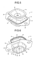
- the mount body 12 has, as shown in FIGS. 5 to 8 , a structure in which a first mounting member 16 and a second mounting member 18 are elastically connected by a main rubber elastic body 20.
- the first mounting member 16 presents a rounded, substantially quadrangular shape when viewed in the axial direction, and is a highly rigid component formed by a plate of iron or aluminum alloy, etc. Its inner circumferential end and outer circumferential end both extend in the substantially axis-perpendicular direction, and its central portion in the axis-perpendicular direction is given a tapered shape that gradually opens upward.
- a bolt insertion hole 22, formed in the central part of the first mounting member 16, has a circular shape with a small diameter that penetrates vertically.
- the first mounting member 16 is configured to be attached to the power unit by bolting the rod member 23,of the power unit using the bolt insertion hole 22.
- the second mounting member 18 is a highly rigid component made of metal, etc., just like the first mounting member 16, and is integrally equipped with a cylindrical portion 24, which extends in the axial direction and has a substantially quadrangular cross-section with its corners rounded in an arc shape, and a flange portion 26, which extends outward in the axis-perpendicular direction from the upper end of the cylindrical portion 24.
- the flange portion 26 projects further out in the front-rear direction than the left-right direction, and is penetrated by a bolt hole 28 on both the front and rear sides.
- This second mounting member 18 is configured to be attached to the vehicle body by overlapping the flange portion 26 on a mounting portion 29 of the vehicle body and using the bolt hole 28 to bolt them together.
- the first mounting member 16 is separated from and positioned above the second mounting member 18, with the first mounting member 16 and the second mounting member 18 elastically connected by the main rubber elastic body 20.
- the main rubber elastic body 20 is given a substantially truncated quadrangular pyramid shape with rounded corners, the edge of its smaller diameter side is bonded by vulcanization to the bottom surface of the first mounting member 16, and the edge of its larger diameter side is bonded by vulcanization to the upper end of the cylindrical portion 24 of the second mounting member 18 and to the flange portion 26.
- the main rubber elastic body 20 is thus formed as an integrally vulcanization molded component equipped with the first mounting member 16 and the second mounting member 18.
- a downward opening recess is formed in the main rubber elastic body 20, and faces downward through the cylindrical portion 24 of the second mounting member 18.
- a housing recess 30, a portion of whose wall is constituted by the main rubber elastic body 20 and which has a substantially quadrangular shape when viewed in the axial direction, is formed at the inner circumference of the cylindrical portion 24 and opens downward in the axial direction.
- the main rubber elastic body 20 is not fixed to the central portion of the first mounting member 16, but the bolt insertion hole 22 of the first mounting member 16 is connected to the housing recess 30 through the center hole in the main rubber elastic body 20.
- the rod member 23, which is inserted into the housing recess 30, is bolted into the bolt insertion hole 22 on the first mounting member 16.
- a rubber sheath layer 32 is fixed to the cylindrical portion 24 of the second mounting member 18.
- the rubber sheath layer 32 is integrally formed with the main rubber elastic body 20, and, with this embodiment, in addition to the inner circumferential surface of the cylindrical portion 24, the rubber sheath layer 32 also covers the axial end surface and outer circumferential surface of the cylindrical portion 24.
- the inner surface of the peripheral wall of the housing recess 30 is integrally composed of the main rubber elastic body 20 and the rubber sheath layer 32.
- Guide protrusions 34 are also provided as a guide portion on the inner surface of the peripheral wall of the housing recess 30, which is composed of the main rubber elastic body 20 and the rubber sheath layer 32.
- Each guide protrusion 34 extends in a substantially unchanging semicircular cross-section in the axial direction from the open end of the housing recess 30 and the guide protrusions 34 are formed in pairs at portions facing in the axis-perpendicular direction on the peripheral wall of the housing recess 30.
- the guide protrusions 34, 34 in each pair are formed and separated in the circumferential direction only by a distance corresponding to the width of the guide projection 38 on the rubber stopper 14 (described later).
- the separate rubber stopper 14 is attached to the mount body 12, which is provided with the above-mentioned structure. As shown in FIGS. 9 to 13 , the rubber stopper 14 is integrally formed overall as an elastic rubber body and has an inverted, substantially quadrangular tubular shape with a bottom. A rod insertion hole 36, which passes through vertically, is formed on the upper bottom wall, and the rod member 23 is inserted therethrough. Although it is desirable that the stopper member is made of an elastic rubber body or an elastic elastomer body, etc., reinforcing material that is made, for example, of metal or a rigid synthetic resin may be embedded inside, and the overall stopper member can be made more rigid.
- a pair of guide projections 38 are also provided on the rubber stopper 14.
- the guide projections 38 protrude outward from sides opposing in one direction (left-right direction) of the rubber stopper 14, and continue in the axial direction with a specific width in the circumferential direction.
- a pair of stopper protrusions 40 are also provided on the rubber stopper 14.
- the stopper protrusions 40 project outward in the front-rear direction from sides opposing in the other direction (front-rear direction) at the top of the rubber stopper 14. With this embodiment, their width narrows vertically toward the projecting tip.
- Dividing grooves 42 are formed opening onto the projecting distal end surface of the stopper protrusions 40 and extend in the axial direction, so that the projecting tips of the stopper protrusions 40 are divided into two sections to both sides of the dividing grooves 42 in the circumferential direction. As shown in FIG. 13 , the dividing grooves 42 in this embodiment have a groove sectional shape with a width that increases toward the projecting tips of the stopper protrusions 40.
- the main body of the rubber stopper 14 except for the guide projections 38 and the stopper protrusions 40 has a substantially rectangular external form when viewed in the axial direction. While the pair of guide projections 38 protrude from sides opposing in the long-side direction of the rubber stopper 14, the pair of stopper protrusions 40 project from sides opposing in the short-side direction.
- the protruding dimension of the stopper protrusions 40 is greater than that of the guide projections 38, so that the rubber stopper 14 is thicker in the axis-perpendicular direction where the stopper protrusions 40 are provided.
- a notch 44 that opens downward in the axial direction is formed at each corner of the rubber stopper 14.
- the notch 44 in this embodiment has a smooth, curved inner surface, so the concentration of the stress on the inner surface of the notch 44 is eased during deformation of the rubber stopper 14.
- the rubber stopper 14 is, as shown in FIGS. 2 to 4 , inserted and positioned in the housing recess 30 of the mount body 12 from below.
- the rubber stopper 14 is guided in the axial direction along those guide protrusions 34.
- the pair of guide projections 38 are pressed against the inner surface of the peripheral wall of the housing recess 30, and the rubber stopper 14 is held in the housing recess 30 through the frictional resistance force that acts between this pair of guide projections 38 and the inner surface of the peripheral wall of the housing recess 30.
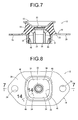
- the means is provided to prevent the rubber stopper 14 from falling out of the housing recess 30. That is, four elastic tapered portions 46 are formed on the inner surface of the peripheral wall of the housing recess 30. As shown in FIG. 14 , the elastic tapered portions 46 are integrally formed with the rubber sheath layer 32 so as to be provided at the opening of the housing recess 30, and are equipped with contact surfaces 48 that gradually incline to the inner circumferential side towards the open side of the housing recess 30. With this embodiment, by gradually making the elastic tapered portions 46, which are provided on the inner circumferential surface of the cylindrical portion 24 of the second mounting member 18, thicker toward the open side of the housing recess 30, the inner circumferential surface of the elastic tapered portions 46 serves as the contact surface 48.
- the elastic tapered portions 46 are, as shown in FIG. 2 , provided at the respective four corners of the housing recess 30. These four elastic tapered portions 46 are separated and distributed at specific distances in the circumferential direction. As also shown in FIG. 2 , the elastic tapered portions 46 that are arranged on circumferentially both sides of another elastic tapered portion 46 are situated in opposing positions, front-rear or left-right.
- each elastic tapered portions 46 at the bottom (inside) of the housing recess 30 is located on the inner circumferential surface of the cylindrical portion 24 of the second mounting member 18, the tip end on the open side of the housing recess 30 extends further outward in the axial direction than the cylindrical portion 24.
- the stopper protrusions 40 pass over the elastic tapered portions 46 when inserted inside the housing recess 30, and the stopper protrusions 40 are thus situated independently from and above the elastic tapered portions 46.
- each stopper protrusion 40 With this embodiment, the corners on circumferentially both sides of each stopper protrusion 40 are pressed against the elastic tapered portions 46, and are made to pass over those elastic tapered portions 46.
- the contact surface area is minimized when the protrusions pass over those elastic tapered portions 46 and frictional resistance is reduced.
- the dividing grooves 42 are formed in the stopper protrusions 40 that open on its distal end surface and extend in the axial direction, elastic deformation of the stopper protrusions 40 is allowed to the circumferentially center side, and the corners can easily pass over the elastic tapered portions 46.
- the corners of the stopper protrusions 40 are placed in contact with the contact surface 48 at the base edge of the elastic tapered portions 46, which are fixed to the inner circumferential surface of the cylindrical portion 24, the elastic deformation of the elastic tapered portions 46 by that contact with the stopper protrusions 40 is limited.
- the rubber stopper 14 is, in this way, more effectively prevented from falling out of the housing recess 30.
- the elastic tapered portions 46 are provided in the four comers of the housing recess 30 whose shapes are stably retained, even if the elastic tapered portions 46 are formed with a comparatively short length in the circumferential direction, deformation is easily limited and the rubber stopper 14 can be advantageously prevented from falling out of the housing recess 30.
- the elastic tapered portions 46 become undercuts when downwardly extracting the mold after forming the surface of the inner wall of the housing recess 30, because each elastic tapered portion 46 is distributed around the circumference with a short circumferential length, removal of that mold is made easy.
- each elastic tapered portion 46 comes in contact with circumferentially both corners of the stopper protrusions 40.
- the reaction force from the contact of the elastic tapered portions 46 and the stopper protrusions 40 acts on the rubber stopper 14 with sufficient balance on the circumference, tilting of the rubber stopper 14 is also prevented and the rubber stopper 14 is held in the housing recess 30 in the specified direction.
- each elastic tapered portion 46 is firmly fixed to the cylindrical portion 24 and is easily molded. Furthermore, because the rubber sheath layer 32 is integrally formed with the main rubber elastic body 20, it becomes possible to easily integrally form the main rubber elastic body 20, the rubber sheath layer 32 and the four elastic tapered portions 46 together.
- the stopper protrusions 40 are position further inside the housing recess 30 than the elastic tapered portions 46 as also shown in FIG. 15A , and are separated without being forcefully pressed against the inner surface of the peripheral wall of the housing recess 30 or in contact with only zero or slight contact pressure.
- the effect of the spring in the rubber stopper 14 on the spring characteristics of the mount body 12 is reduced in relation to input of a small amplitude vibration in the axis-perpendicular direction, and by obtaining the target spring characteristics (low dynamic spring characteristics), an effective vibration damping effect (vibration isolation effect) is demonstrated.
- the lower portion of the rubber stopper 14 that is separated from the stopper protrusions 40 is formed with a sufficiently small external form in the front-rear direction in comparison with the internal dimensions of the opening of the housing recess 30, by positioning the stopper protrusions 40 further inside the housing recess 30 than the elastic tapered portions 46, contact between the rubber stopper 14 and the elastic tapered portions 46 is avoided.
- the elastic tapered portions need not necessarily be formed in plurality; only one is sufficient.
- one elastic tapered portion may be provided continuously all around the circumference.
- the position where the elastic tapered portions are formed in the depth direction of the housing recess does not need to be limited to the open edge of the housing recess, but may be in the central portion in the depth direction of the housing recess.
- the elastic tapered portion may be situated so as to overlap the cylindrical portion in its entirety when viewed in axis-perpendicular direction projection.
- the elastic tapered portions do not necessarily need to be formed in the corners of the housing recess; they may also be provided on the sides of the housing recess. As is also clear from this, the circumferentially central portion of the stopper protrusions may also overlap the elastic tapered portions when viewed in axial direction projection.
- the elastic tapered portions are not limited to the structure in the above-mentioned embodiment, wherein they are formed by an elastic rubber body that is gradually thicker toward the open side of the housing recess.
- they can also be provided by drawing operation etc. of the bottom of the cylindrical portion so as to make a slanted shape that inclines inward towards the bottom.
- the housing recess is not limited to being quadrangular in shape when viewed in the axial direction but may be circular.
- a cylindrical or other shape may be employed for the stopper member. It is desirable for the shape of the housing recess and stopper member when viewed in the axial direction to substantially correspond to each other, but it is also possible to use mutually different forms for the shape of the housing recess and stopper member when viewed in the axial direction.
- a cylindrical stopper member may be positioned in a housing recess that is quadrangular in shape when viewed in the axial direction.
- the stopper member is formed overall with an elastic rubber body in the above-mentioned embodiment, in order, for example, to aim at a more stabilized form and improved load bearing characteristics, etc., rigid reinforcing components made of metal or a synthetic resin may be embedded inside.
- the scope of this invention is not limited to an engine mount, and may also be applied to a vibration damping device used as a subframe mount, a body mount, a differential mount, etc. Moreover, this invention does not apply only to a vibration damping device for automobiles but, for example, may also be applied to vibration damping devices used on motorcycles, rolling stock for railways, industrial vehicles, etc.
- 10 engine mount (vibration damping device), 14: rubber stopper (stopper member), 16: first mounting member, 18: second mounting member, 20: main rubber elastic body, 24: cylindrical portion, 30: housing recess, 32: rubber sheath layer, 34: guide protrusion (guide portion), 40: stopper protrusion, 42: dividing groove, 44: notch, 46: elastic tapered portion, 48: contact surface
Applications Claiming Priority (1)
| Application Number | Priority Date | Filing Date | Title |
|---|---|---|---|
| PCT/JP2013/005087 WO2015029086A1 (fr) | 2013-08-28 | 2013-08-28 | Dispositif amortisseur de vibrations |
Publications (3)
| Publication Number | Publication Date |
|---|---|
| EP3040575A1 true EP3040575A1 (fr) | 2016-07-06 |
| EP3040575A4 EP3040575A4 (fr) | 2017-07-05 |
| EP3040575B1 EP3040575B1 (fr) | 2018-06-27 |
Family
ID=51409512
Family Applications (1)
| Application Number | Title | Priority Date | Filing Date |
|---|---|---|---|
| EP13866484.2A Active EP3040575B1 (fr) | 2013-08-28 | 2013-08-28 | Dispositif amortisseur de vibrations |
Country Status (4)
| Country | Link |
|---|---|
| US (1) | US9394958B2 (fr) |
| EP (1) | EP3040575B1 (fr) |
| JP (1) | JP5543047B1 (fr) |
| WO (1) | WO2015029086A1 (fr) |
Families Citing this family (4)
| Publication number | Priority date | Publication date | Assignee | Title |
|---|---|---|---|---|
| CN104859396A (zh) * | 2015-06-01 | 2015-08-26 | 安徽江淮汽车股份有限公司 | 一种钢板弹簧盖板结构 |
| DE102015122226B4 (de) * | 2015-12-18 | 2022-05-19 | Vibracoustic Se | Motorlager-Pendelstützen-Vorrichtung |
| JP6785612B2 (ja) * | 2016-10-12 | 2020-11-18 | 山下ゴム株式会社 | 防振装置構造 |
| JP6909571B2 (ja) * | 2016-11-04 | 2021-07-28 | 住友理工株式会社 | 防振装置 |
Family Cites Families (16)
| Publication number | Priority date | Publication date | Assignee | Title |
|---|---|---|---|---|
| US3671065A (en) * | 1970-12-11 | 1972-06-20 | Amerock Corp | Slidable bolt catch |
| US4842258A (en) * | 1987-04-17 | 1989-06-27 | Toyota Jidosha Kabushiki Kaisha | Composite engine mount |
| DE4011827A1 (de) * | 1990-04-12 | 1991-10-17 | Daimler Benz Ag | Abstuetzlager |
| DE29920496U1 (de) * | 1999-11-23 | 2000-02-17 | Schwarz Verbindungs Sys Gmbh | Schwingungsdämpfende Verbindungsanordnung für zwei gegeneinander verschiebliche Bauteile |
| DE10251877B4 (de) * | 2002-11-07 | 2008-08-07 | Trelleborg Automotive Technical Centre Gmbh | Hydraulisch dämpfendes Lager, insbesondere zum Abstützen des Motors eines Kraftfahrzeugs |
| EP1649179A1 (fr) * | 2003-07-03 | 2006-04-26 | Cooper-Standard Automotive Inc. | Montage rapide d'isolateur de palier intermediaire en plastique et procede de fabrication et d'assemblage de celui-ci |
| JP3989482B2 (ja) * | 2004-11-04 | 2007-10-10 | 本田技研工業株式会社 | 防振装置 |
| JP4842078B2 (ja) * | 2006-01-31 | 2011-12-21 | 東海ゴム工業株式会社 | 流体封入式防振装置およびその製造方法 |
| EP2025968B1 (fr) * | 2006-06-05 | 2014-05-21 | Bridgestone Corporation | Dispositif d'isolement contre les vibrations |
| JP2008002565A (ja) * | 2006-06-22 | 2008-01-10 | Toyo Tire & Rubber Co Ltd | 防振装置 |
| JP2008248898A (ja) * | 2007-03-29 | 2008-10-16 | Tokai Rubber Ind Ltd | 筒型防振装置 |
| FR2916503B1 (fr) * | 2007-05-24 | 2010-09-10 | Hutchinson | Dispositif antivibratoire. |
| JP2010174957A (ja) * | 2009-01-28 | 2010-08-12 | Kurashiki Kako Co Ltd | エンジンマウントのストッパ取付構造 |
| US9163695B2 (en) * | 2010-03-08 | 2015-10-20 | Bridgestone Corporation | Liquid-sealed anti-vibration device and method for manufacturing the same |
| FR2973088A1 (fr) * | 2011-03-21 | 2012-09-28 | Hutchinson | Support antivibratoire et vehicule comportant un tel support |
| DE102012014318B4 (de) * | 2012-07-19 | 2016-10-20 | Anvis Deutschland Gmbh | Federfunktionsbauteil für ein hydroelastisches Lager und hydroelastisches Lager |
-
2013
- 2013-08-28 JP JP2014508404A patent/JP5543047B1/ja active Active
- 2013-08-28 EP EP13866484.2A patent/EP3040575B1/fr active Active
- 2013-08-28 WO PCT/JP2013/005087 patent/WO2015029086A1/fr active Application Filing
-
2014
- 2014-05-21 US US14/283,684 patent/US9394958B2/en active Active
Non-Patent Citations (1)
| Title |
|---|
| See references of WO2015029086A1 * |
Also Published As
| Publication number | Publication date |
|---|---|
| EP3040575B1 (fr) | 2018-06-27 |
| EP3040575A4 (fr) | 2017-07-05 |
| WO2015029086A1 (fr) | 2015-03-05 |
| US20150061202A1 (en) | 2015-03-05 |
| US9394958B2 (en) | 2016-07-19 |
| JP5543047B1 (ja) | 2014-07-09 |
| JPWO2015029086A1 (ja) | 2017-03-02 |
Similar Documents
| Publication | Publication Date | Title |
|---|---|---|
| US9027912B2 (en) | Vibration damping device | |
| US9518628B2 (en) | Tubular vibration-damping device | |
| WO2014050761A1 (fr) | Dispositif anti-vibration | |
| JP4283858B2 (ja) | 防振マウント組立体 | |
| US9200690B2 (en) | Cylindrical vibration-damping device | |
| EP3040575B1 (fr) | Dispositif amortisseur de vibrations | |
| WO2015045750A1 (fr) | Isolateur de vibrations cylindrique | |
| CN109927499B (zh) | 悬架用上支撑件 | |
| JP2008089002A (ja) | 筒型防振装置用ストッパ並びに筒型防振組付体 | |
| US9739337B2 (en) | Vibration damping device | |
| EP3009709A1 (fr) | Dispositif d'amortissement des vibrations | |
| WO2017056415A1 (fr) | Structure de montage de moteur | |
| JP6710140B2 (ja) | 防振装置 | |
| JP5646213B2 (ja) | 防振装置 | |
| JP6297368B2 (ja) | 防振装置 | |
| JP6768395B2 (ja) | 筒形防振装置 | |
| EP2249056A1 (fr) | Dispositif d'amortissement des vibrations | |
| JP6537958B2 (ja) | ブラケット付き防振装置 | |
| JP6867773B2 (ja) | 防振装置 | |
| JP2015212563A (ja) | 防振装置 | |
| JP2011247333A (ja) | 防振支持構造 | |
| JP6040031B2 (ja) | 防振装置 | |
| US20190048956A1 (en) | Vibration damping device | |
| CN112922988B (zh) | 带托架的筒型防振装置 | |
| CN108215756B (zh) | 动力传动系的安装装置 |
Legal Events
| Date | Code | Title | Description |
|---|---|---|---|
| PUAI | Public reference made under article 153(3) epc to a published international application that has entered the european phase |
Free format text: ORIGINAL CODE: 0009012 |
|
| 17P | Request for examination filed |
Effective date: 20140618 |
|
| AK | Designated contracting states |
Kind code of ref document: A1 Designated state(s): AL AT BE BG CH CY CZ DE DK EE ES FI FR GB GR HR HU IE IS IT LI LT LU LV MC MK MT NL NO PL PT RO RS SE SI SK SM TR |
|
| AX | Request for extension of the european patent |
Extension state: BA ME |
|
| DAX | Request for extension of the european patent (deleted) | ||
| A4 | Supplementary search report drawn up and despatched |
Effective date: 20170601 |
|
| RIC1 | Information provided on ipc code assigned before grant |
Ipc: F16F 1/38 20060101ALI20170526BHEP Ipc: F16F 3/08 20060101AFI20170526BHEP Ipc: F16F 13/10 20060101ALI20170526BHEP Ipc: F16F 15/08 20060101ALI20170526BHEP Ipc: F16F 1/371 20060101ALI20170526BHEP Ipc: F16F 3/087 20060101ALI20170526BHEP Ipc: B60K 5/12 20060101ALI20170526BHEP Ipc: F16F 1/36 20060101ALI20170526BHEP |
|
| GRAP | Despatch of communication of intention to grant a patent |
Free format text: ORIGINAL CODE: EPIDOSNIGR1 |
|
| INTG | Intention to grant announced |
Effective date: 20180321 |
|
| GRAS | Grant fee paid |
Free format text: ORIGINAL CODE: EPIDOSNIGR3 |
|
| GRAA | (expected) grant |
Free format text: ORIGINAL CODE: 0009210 |
|
| AK | Designated contracting states |
Kind code of ref document: B1 Designated state(s): AL AT BE BG CH CY CZ DE DK EE ES FI FR GB GR HR HU IE IS IT LI LT LU LV MC MK MT NL NO PL PT RO RS SE SI SK SM TR |
|
| REG | Reference to a national code |
Ref country code: GB Ref legal event code: FG4D |
|
| RIN1 | Information on inventor provided before grant (corrected) |
Inventor name: SETOYAMA, TOYOSHI |
|
| REG | Reference to a national code |
Ref country code: AT Ref legal event code: REF Ref document number: 1012624 Country of ref document: AT Kind code of ref document: T Effective date: 20180715 |
|
| REG | Reference to a national code |
Ref country code: IE Ref legal event code: FG4D |
|
| REG | Reference to a national code |
Ref country code: DE Ref legal event code: R096 Ref document number: 602013039550 Country of ref document: DE |
|
| REG | Reference to a national code |
Ref country code: FR Ref legal event code: PLFP Year of fee payment: 6 |
|
| PG25 | Lapsed in a contracting state [announced via postgrant information from national office to epo] |
Ref country code: NO Free format text: LAPSE BECAUSE OF FAILURE TO SUBMIT A TRANSLATION OF THE DESCRIPTION OR TO PAY THE FEE WITHIN THE PRESCRIBED TIME-LIMIT Effective date: 20180927 Ref country code: BG Free format text: LAPSE BECAUSE OF FAILURE TO SUBMIT A TRANSLATION OF THE DESCRIPTION OR TO PAY THE FEE WITHIN THE PRESCRIBED TIME-LIMIT Effective date: 20180927 Ref country code: FI Free format text: LAPSE BECAUSE OF FAILURE TO SUBMIT A TRANSLATION OF THE DESCRIPTION OR TO PAY THE FEE WITHIN THE PRESCRIBED TIME-LIMIT Effective date: 20180627 Ref country code: SE Free format text: LAPSE BECAUSE OF FAILURE TO SUBMIT A TRANSLATION OF THE DESCRIPTION OR TO PAY THE FEE WITHIN THE PRESCRIBED TIME-LIMIT Effective date: 20180627 Ref country code: LT Free format text: LAPSE BECAUSE OF FAILURE TO SUBMIT A TRANSLATION OF THE DESCRIPTION OR TO PAY THE FEE WITHIN THE PRESCRIBED TIME-LIMIT Effective date: 20180627 |
|
| REG | Reference to a national code |
Ref country code: NL Ref legal event code: MP Effective date: 20180627 |
|
| REG | Reference to a national code |
Ref country code: LT Ref legal event code: MG4D |
|
| PG25 | Lapsed in a contracting state [announced via postgrant information from national office to epo] |
Ref country code: RS Free format text: LAPSE BECAUSE OF FAILURE TO SUBMIT A TRANSLATION OF THE DESCRIPTION OR TO PAY THE FEE WITHIN THE PRESCRIBED TIME-LIMIT Effective date: 20180627 Ref country code: HR Free format text: LAPSE BECAUSE OF FAILURE TO SUBMIT A TRANSLATION OF THE DESCRIPTION OR TO PAY THE FEE WITHIN THE PRESCRIBED TIME-LIMIT Effective date: 20180627 Ref country code: LV Free format text: LAPSE BECAUSE OF FAILURE TO SUBMIT A TRANSLATION OF THE DESCRIPTION OR TO PAY THE FEE WITHIN THE PRESCRIBED TIME-LIMIT Effective date: 20180627 Ref country code: GR Free format text: LAPSE BECAUSE OF FAILURE TO SUBMIT A TRANSLATION OF THE DESCRIPTION OR TO PAY THE FEE WITHIN THE PRESCRIBED TIME-LIMIT Effective date: 20180928 |
|
| REG | Reference to a national code |
Ref country code: AT Ref legal event code: MK05 Ref document number: 1012624 Country of ref document: AT Kind code of ref document: T Effective date: 20180627 |
|
| PG25 | Lapsed in a contracting state [announced via postgrant information from national office to epo] |
Ref country code: NL Free format text: LAPSE BECAUSE OF FAILURE TO SUBMIT A TRANSLATION OF THE DESCRIPTION OR TO PAY THE FEE WITHIN THE PRESCRIBED TIME-LIMIT Effective date: 20180627 |
|
| PG25 | Lapsed in a contracting state [announced via postgrant information from national office to epo] |
Ref country code: PL Free format text: LAPSE BECAUSE OF FAILURE TO SUBMIT A TRANSLATION OF THE DESCRIPTION OR TO PAY THE FEE WITHIN THE PRESCRIBED TIME-LIMIT Effective date: 20180627 Ref country code: AT Free format text: LAPSE BECAUSE OF FAILURE TO SUBMIT A TRANSLATION OF THE DESCRIPTION OR TO PAY THE FEE WITHIN THE PRESCRIBED TIME-LIMIT Effective date: 20180627 Ref country code: IS Free format text: LAPSE BECAUSE OF FAILURE TO SUBMIT A TRANSLATION OF THE DESCRIPTION OR TO PAY THE FEE WITHIN THE PRESCRIBED TIME-LIMIT Effective date: 20181027 Ref country code: RO Free format text: LAPSE BECAUSE OF FAILURE TO SUBMIT A TRANSLATION OF THE DESCRIPTION OR TO PAY THE FEE WITHIN THE PRESCRIBED TIME-LIMIT Effective date: 20180627 Ref country code: CZ Free format text: LAPSE BECAUSE OF FAILURE TO SUBMIT A TRANSLATION OF THE DESCRIPTION OR TO PAY THE FEE WITHIN THE PRESCRIBED TIME-LIMIT Effective date: 20180627 Ref country code: EE Free format text: LAPSE BECAUSE OF FAILURE TO SUBMIT A TRANSLATION OF THE DESCRIPTION OR TO PAY THE FEE WITHIN THE PRESCRIBED TIME-LIMIT Effective date: 20180627 Ref country code: SK Free format text: LAPSE BECAUSE OF FAILURE TO SUBMIT A TRANSLATION OF THE DESCRIPTION OR TO PAY THE FEE WITHIN THE PRESCRIBED TIME-LIMIT Effective date: 20180627 |
|
| PG25 | Lapsed in a contracting state [announced via postgrant information from national office to epo] |
Ref country code: SM Free format text: LAPSE BECAUSE OF FAILURE TO SUBMIT A TRANSLATION OF THE DESCRIPTION OR TO PAY THE FEE WITHIN THE PRESCRIBED TIME-LIMIT Effective date: 20180627 Ref country code: IT Free format text: LAPSE BECAUSE OF FAILURE TO SUBMIT A TRANSLATION OF THE DESCRIPTION OR TO PAY THE FEE WITHIN THE PRESCRIBED TIME-LIMIT Effective date: 20180627 Ref country code: ES Free format text: LAPSE BECAUSE OF FAILURE TO SUBMIT A TRANSLATION OF THE DESCRIPTION OR TO PAY THE FEE WITHIN THE PRESCRIBED TIME-LIMIT Effective date: 20180627 |
|
| REG | Reference to a national code |
Ref country code: DE Ref legal event code: R097 Ref document number: 602013039550 Country of ref document: DE |
|
| PG25 | Lapsed in a contracting state [announced via postgrant information from national office to epo] |
Ref country code: MC Free format text: LAPSE BECAUSE OF FAILURE TO SUBMIT A TRANSLATION OF THE DESCRIPTION OR TO PAY THE FEE WITHIN THE PRESCRIBED TIME-LIMIT Effective date: 20180627 |
|
| REG | Reference to a national code |
Ref country code: CH Ref legal event code: PL |
|
| PG25 | Lapsed in a contracting state [announced via postgrant information from national office to epo] |
Ref country code: CH Free format text: LAPSE BECAUSE OF NON-PAYMENT OF DUE FEES Effective date: 20180831 Ref country code: LI Free format text: LAPSE BECAUSE OF NON-PAYMENT OF DUE FEES Effective date: 20180831 Ref country code: LU Free format text: LAPSE BECAUSE OF NON-PAYMENT OF DUE FEES Effective date: 20180828 |
|
| PLBE | No opposition filed within time limit |
Free format text: ORIGINAL CODE: 0009261 |
|
| STAA | Information on the status of an ep patent application or granted ep patent |
Free format text: STATUS: NO OPPOSITION FILED WITHIN TIME LIMIT |
|
| REG | Reference to a national code |
Ref country code: BE Ref legal event code: MM Effective date: 20180831 |
|
| GBPC | Gb: european patent ceased through non-payment of renewal fee |
Effective date: 20180927 |
|
| PG25 | Lapsed in a contracting state [announced via postgrant information from national office to epo] |
Ref country code: DK Free format text: LAPSE BECAUSE OF FAILURE TO SUBMIT A TRANSLATION OF THE DESCRIPTION OR TO PAY THE FEE WITHIN THE PRESCRIBED TIME-LIMIT Effective date: 20180627 |
|
| 26N | No opposition filed |
Effective date: 20190328 |
|
| PG25 | Lapsed in a contracting state [announced via postgrant information from national office to epo] |
Ref country code: BE Free format text: LAPSE BECAUSE OF NON-PAYMENT OF DUE FEES Effective date: 20180831 Ref country code: SI Free format text: LAPSE BECAUSE OF FAILURE TO SUBMIT A TRANSLATION OF THE DESCRIPTION OR TO PAY THE FEE WITHIN THE PRESCRIBED TIME-LIMIT Effective date: 20180627 |
|
| PG25 | Lapsed in a contracting state [announced via postgrant information from national office to epo] |
Ref country code: GB Free format text: LAPSE BECAUSE OF NON-PAYMENT OF DUE FEES Effective date: 20180927 |
|
| PG25 | Lapsed in a contracting state [announced via postgrant information from national office to epo] |
Ref country code: AL Free format text: LAPSE BECAUSE OF FAILURE TO SUBMIT A TRANSLATION OF THE DESCRIPTION OR TO PAY THE FEE WITHIN THE PRESCRIBED TIME-LIMIT Effective date: 20180627 |
|
| PG25 | Lapsed in a contracting state [announced via postgrant information from national office to epo] |
Ref country code: MT Free format text: LAPSE BECAUSE OF NON-PAYMENT OF DUE FEES Effective date: 20180828 |
|
| PG25 | Lapsed in a contracting state [announced via postgrant information from national office to epo] |
Ref country code: TR Free format text: LAPSE BECAUSE OF FAILURE TO SUBMIT A TRANSLATION OF THE DESCRIPTION OR TO PAY THE FEE WITHIN THE PRESCRIBED TIME-LIMIT Effective date: 20180627 |
|
| PG25 | Lapsed in a contracting state [announced via postgrant information from national office to epo] |
Ref country code: PT Free format text: LAPSE BECAUSE OF FAILURE TO SUBMIT A TRANSLATION OF THE DESCRIPTION OR TO PAY THE FEE WITHIN THE PRESCRIBED TIME-LIMIT Effective date: 20180627 |
|
| PG25 | Lapsed in a contracting state [announced via postgrant information from national office to epo] |
Ref country code: HU Free format text: LAPSE BECAUSE OF FAILURE TO SUBMIT A TRANSLATION OF THE DESCRIPTION OR TO PAY THE FEE WITHIN THE PRESCRIBED TIME-LIMIT; INVALID AB INITIO Effective date: 20130828 Ref country code: MK Free format text: LAPSE BECAUSE OF NON-PAYMENT OF DUE FEES Effective date: 20180627 Ref country code: CY Free format text: LAPSE BECAUSE OF FAILURE TO SUBMIT A TRANSLATION OF THE DESCRIPTION OR TO PAY THE FEE WITHIN THE PRESCRIBED TIME-LIMIT Effective date: 20180627 Ref country code: IE Free format text: LAPSE BECAUSE OF NON-PAYMENT OF DUE FEES Effective date: 20180828 |
|
| PGFP | Annual fee paid to national office [announced via postgrant information from national office to epo] |
Ref country code: FR Payment date: 20230703 Year of fee payment: 11 Ref country code: DE Payment date: 20230703 Year of fee payment: 11 |