EP3040487B2 - Düsenanordnung für ein bidet - Google Patents
Düsenanordnung für ein bidet Download PDFInfo
- Publication number
- EP3040487B2 EP3040487B2 EP14839410.9A EP14839410A EP3040487B2 EP 3040487 B2 EP3040487 B2 EP 3040487B2 EP 14839410 A EP14839410 A EP 14839410A EP 3040487 B2 EP3040487 B2 EP 3040487B2
- Authority
- EP
- European Patent Office
- Prior art keywords
- nozzle
- nozzle unit
- unit
- bidet
- nozzle assembly
- Prior art date
- Legal status (The legal status is an assumption and is not a legal conclusion. Google has not performed a legal analysis and makes no representation as to the accuracy of the status listed.)
- Active
Links
Images


Classifications
-
- E—FIXED CONSTRUCTIONS
- E03—WATER SUPPLY; SEWERAGE
- E03D—WATER-CLOSETS OR URINALS WITH FLUSHING DEVICES; FLUSHING VALVES THEREFOR
- E03D9/00—Sanitary or other accessories for lavatories ; Devices for cleaning or disinfecting the toilet room or the toilet bowl; Devices for eliminating smells
- E03D9/08—Devices in the bowl producing upwardly-directed sprays; Modifications of the bowl for use with such devices ; Bidets; Combinations of bowls with urinals or bidets; Hot-air or other devices mounted in or on the bowl, urinal or bidet for cleaning or disinfecting
Definitions
- the present invention relates to a nozzle assembly for a bidet, and more particularly, to a nozzle assembly for a bidet including a nozzle configured in such a manner that an ejection position thereof is adjustable at a predetermined interval and configured to make a curved movement.
- a nozzle assembly for a bidet is installed in a bidet unit in case of a bidet integrated with a toilet, and is installed in a bidet main body in case of a bidet toilet seat as a conventional bidet, and includes a nozzle movably provided therein to dispense water to private parts of a user to clean the same.
- the nozzle provided in the nozzle assembly for a bidet is positioned within a nozzle housing in an idle state (when not in use), and when the user operates the bidet after passing a bowel movement, the nozzle is moved to a water ejection position to clean external areas.
- the related art nozzle is provided to make a linear movement in a sloped state in the nozzle assembly for a bidet. Also, in the related art nozzle assembly, an injection-molded product as a water supply channel is assembled within a nozzle cylinder formed of a material such as stainless steel, or the like, and a water supply hole connected to the water supply channel is connected to a rear end using a connector.
- the nozzle is provided in the nozzle assembly for a bidet in such a manner that the nozzle makes a linear movement slantingly, a relatively large space is required for such a nozzle movement in a bidet unit in the case of the bidet integrated with a toilet or in the bidet main body in the case of the bidet toilet seat as a conventional bidet in which the nozzle assembly for a bidet installed.
- a deep recess should be formed in a toilet bowl or a height of a part where the bidet is installed should be high, and in the bidet toilet seat as a conventional bidet, a height of the bidet main body should be high.
- US 2013/0152295 A1 discloses an adjustable water jet device having a nozzle assembly comprising a nozzle unit making a curved movement, a water supply hose connected to the nozzle unit and to a water source, and a driving unit having a winding member rotatably driven to adjust a length of the nozzle unit and driving the nozzle unit to make a curved movement.
- US 2006/0070173 A1 discloses a nozzle assembly including a nozzle, a driving motor for driving the nozzle, a gear train and a nozzle case.
- the gear train includes a driving gear connected to the driving motor, and a nozzle gear reciprocating the nozzle by receiving rotational force from the driving gear.
- EP 2 503 070 A1 discloses an injection member assembly having a movable injection member, a bracket with a guiding surface and a driving assembly.
- the driving assembly includes a driving device and a coupling member coupled with the guiding surface.
- the movable injection member is connected to one or both of the driving assembly and the bracket.
- An aspect of the present invention provides a nozzle assembly for a bidet in which intervals of water ejection positions are adjusted to be equal by differentiating angles at which a winding member is rotated to change a length of extension of a nozzle from one step to an adjacent higher step, in multiple steps.
- a nozzle assembly for a bidet including: a nozzle unit making a curved movement and including a water supply hose connected to a water source; and a driving unit having a winding member rotatably driven to adjust a length of the nozzle unit and driving the nozzle unit to make a curved movement, wherein the length of the nozzle unit is adjusted by stages, and a exit-out rotation angle at which the winding member rotates to change the length of the nozzle unit from any one step to an adjacent higher step is different in each step.
- the nozzle unit may include a cylinder member having a curved shape with a hollow formed therein, and the water supply hose may be disposed in the hollow.
- the nozzle unit may be mounted on an upper portion of a movement guide member provided to correspond to a shape of the nozzle unit, and may make a curved movement.
- the movement guide member may have a curved shape.
- the length of the nozzle unit is increased from a lower step to a higher step.
- a lead-in rotation angle at which the winding member rotates to change the length of the nozzle unit from the adjacent higher step to the any one step may be the opposite in direction to the exit-out rotation angle direction and may have the same value.
- the exit-out rotation angle is reduced in a direction toward a higher step.
- a decrease of the exit-out rotation angle may be reduced in a direction toward a higher step.
- the driving unit may include: a connection member having one side fixedly coupled to the nozzle unit and the other side connected to the winding member; and a driving motor connected to the winding member to provide rotational force to the winding member.
- connection member may be provided as a belt gear having one side fixedly coupled to a lower end of a connector member.
- intervals of water ejection positions may be adjusted to be equal by differentiating angles at which the winding member rotates to change a length of extension of the nozzle from one step to an adjacent higher step by stages.
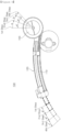
- FIG. 3 is a perspective view illustrating a nozzle assembly for a bidet according to an embodiment of the present disclosure
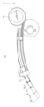
- FIG. 4 is a side view illustrating a case in which a nozzle unit of the nozzle assembly for a bidet illustrated in FIG. 3 is in the original position
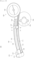
- FIG. 5 is a side cross-sectional view of the nozzle assembly for a bidet of FIG. 4
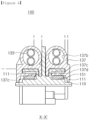
- FIG. 6 is a cross-sectional view taken along line X-X' of FIG. 4
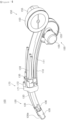
- FIG. 7 is a perspective view illustrating a state in which a nozzle unit of the nozzle assembly for a bidet illustrated in FIG. 3 is drawn out.
- a nozzle unit 130 is configured to make a curved movement so that a space occupied by the nozzle assembly 100 for a bidet in a bidet main body is reduced.
- the nozzle assembly 100 for a bidet may include a movement guide member 110, the nozzle unit 130, and a driving unit 150.
- the movement guide member 110 is provided to correspond to a shape of the nozzle unit 130, and, preferably, has a curved shape. Thus, as described hereinafter, the nozzle unit 130 is guided to make a curved movement along the movement guide member 110.
- the nozzle unit 130 may make a curved movement along the movement guide member 110, and may include a cylinder member 131 in which a water supply hose 133 connected to a water source (not shown) is installed.
- the nozzle unit 130 may be mounted on the movement guide member 110 and installed to be movable in a forward/backward direction along the movement guide member 110.
- the movement guide member 110 has a curved shape, the nozzle unit 130 makes a curved movement in the forward/backward direction.
- the nozzle unit 130 may be provided to have a curved shape to make a curved movement.
- the cylinder member 131 may be formed of generally used stainless steel, but a material of the cylinder member 131 is not limited thereto. and various modifications may be made.
- the nozzle unit 130 may include the cylinder member 131 with a hollow formed therein and the water supply hose 133 disposed in the hollow of the cylinder member 131.
- the water supply hose 133 may be connected to a water source and may supply cleaning water to the nozzle unit 130.
- the water supply hose 133 may be formed as a flexible pipe, and in this case, a rubber hose, a fabric hose, or a silicon hose may be formed of a synthetic resin pipe.
- a material of the water supply hose 133 is not limited thereto, and may be variously modified.
- the driving unit 150 may be connected to the nozzle unit 130 and provide power for the nozzle unit 130 to move along the movement guide member 110.
- driving unit 150 there are no limitations in a structure or type of the driving unit 150, and various types of driving units may be applied as long as they may be able to move the nozzle unit 130 in the forward/backward direction along the movement guide member 110.
- the nozzle unit 130 may make a curved movement, and thus, the nozzle unit 130 may move even in a small space.
- a shallow recess may be formed in a toilet unit to install a bidet unit therein, and in case of a bidet toilet seat as a conventional bidet, a height of a bidet main body may be lowered.
- the cylinder member 131 of the nozzle unit 130 has a curved shape corresponding to the movement guide member 110.
- the nozzle unit 130 When the nozzle unit 130 has a curved shape corresponding to the movement guide member 110, the nozzle unit 130 smoothly makes a curved movement along the movement guide member 110. Also, since the nozzle unit 130 has the curved shape, an area occupied by the bidet unit may be reduced.
- the shape of the cylinder member 131 is not limited to the illustrated embodiment, and the cylinder member 131 may be modified to various shapes as long as the nozzle unit 130 makes a curved movement.
- the water supply hose 133 is formed of a flexible material, the water supply hose 133 may be installed to be easily deformed according to a shape of the cylinder member 131 within the curved cylinder member 131.
- the nozzle 130 may include a nozzle tip 135 connected to a front end of the cylinder member 131 and a connector 136 connected to the nozzle tip 135 in such a manner that the connector 136 communicates with an ejection hole 135a, and inserted within the cylinder member 131 in such a manner that one end of the water supply hose 133 is insert-coupled thereto.
- the nozzle tip 135 is provided at a font end of the cylinder member 131 to dispense cleaning water to private parts of a user.
- the ejection hole 135a may be formed to communicate with the connector 136 (to be described hereinafter) and dispense cleaning water supplied through the connector 136.
- the nozzle tip 135 may be detachably connected to the cylinder member 131.
- the connector 136 may be connected to the nozzle tip 135 in such a manner that the connector 136 communicates with the ejection hole 135a, and may be inserted within the cylinder member 131.
- the connector 136 may be insert-coupled to one end of the water supply hose 133.
- the connector 136 may be connected to the water supply hose 133 connected to a water supply pipe, and cleaning water supplied from the water supply pipe may move up to the ejection hole 135a.
- the connector 135, to which the water supply hose 133 is connected is provided at a front end of the cylinder member 131, and the water supply hose 133 may be connected to the interior of the cylinder member 131.
- the connector 136 may be provided in plurality, and the water supply hose 133 may be provided in plurality within the cylinder member 131 to form a plurality of flow channels.
- the water supply hose 133 connected to the water source, not a plastic injection-molded product is directly installed within the cylinder member 131 to form a cleaning water flow channel, whereby the water supply hose 133 may be easily installed within the cylinder member 131 manufactured to have a curved shape, and a plurality of water supply hoses 133 may be easily installed within the cylinder member 131.
- the nozzle unit 130 may form various water streams. That is, since a plurality of cleaning water flow channels are formed, a wide water stream, a linear water stream, and a water stream for nozzle cleaning may be formed according to each of connection holes and a size of the water supply hose 133 connected to each of the connection holes, and a velocity of water supplied to the water supply hose 133.
- the nozzle unit 130 may include a connector member 137 having a through hole member 137b coupled to the other end of the cylinder member 131 and allowing the water supply hose 133 to pass therethrough, to fix the water supply hose 133.
- the connector member 137 may be insert-coupled to the other end of the cylinder member 131 and have the through hole member 137b.
- the through hole member 137b may serve to fix the water supply hose 133 when the water supply hose 133 passes therethrough.
- the connector member 137 may have a guide protrusion 137c formed to be inserted into a guide groove 111 of the movement guide member 110, prevent release of the cylinder member 131, and guide movement of the cylinder member 131.
- the guide groove 111 may be formed in a direction in which the nozzle unit 130 moves, and, as in the illustrated embodiment, the guide groove 111 may be formed in plurality.
- the guide protrusion 137c of the connector member 137 may be installed to be inserted into a position corresponding to the guide groove 111 to guide a slidable movement of the cylinder member 131 when the cylinder member 131 moves in a forward/backward direction and prevent release of the cylinder member 131 from the movement guide member 110.
- the formation and the number of the guide protrusions 137c and the guide groove 111 are not limited to the illustrated case, and may be variously modified.
- the nozzle assembly 100 for a bidet may further include a nozzle duct unit 170 fixedly installed at a front end of the movement guide member 110 to protect the nozzle unit 130 and allowing the nozzle unit 130 to pass therethrough to guide movement of the nozzle unit 130.
- the nozzle duct unit 170 may be fixedly installed at a front end of the movement guide member 110 and include a through hole allowing the cylinder member 131 to pass therethrough.
- the nozzle duct unit 170 may cover the nozzle tip 135 to protect the nozzle tip 135, and as illustrated in FIG. 7 , when the nozzle unit 130 is drawn out, the nozzle duct unit 170 may guide slidable movement of the nozzle unit 130.
- the nozzle duct unit 170 may serve as a stopper fixedly installed at the front end of the movement guide member 110 to allow the connector member 137 connected to the other end of the cylinder member 131 to be caught thereby, thus limiting movement of the cylinder member 131.
- the nozzle duct unit 170 may include a self-cleaning member 171 having a cleaning water inlet 172 to dispense cleaning water to the nozzle tip 135 provided in the nozzle unit 130 when the nozzle unit 130 is in the original position.
- the cleaning water inlet 172 may be connected to communicate with an upper portion of the nozzle tip 135, and the cleaning water inlet 172 may be connected to the water source.
- the self-cleaning member 171 may remove fecal matter from the nozzle tip 135.
- the driving unit 150 may include a connection member 151 having one side fixedly coupled to the nozzle unit 130, a winding member 153 connected to the other side of the connection member 151 and allowing the connection member 151 to be wound therearound or drawn out according to rotation, and a driving motor 155 connected to the winding member 153 and providing rotational force to the winding member 153.
- connection member 151 may be provided as a belt gear 151 having one side fixedly coupled to a lower end of the connector member 137.
- one end of the belt gear 151 and the connector member 137 may be fixedly coupled.
- connection member 151 provided as the belt gear 151 may be wound around the winding member.
- the winding member 153 may include a spur gear 154, and the spur gear 154 and the belt gear 151 may be engaged with each other.
- the spur gear 154 may be connected to the driving motor 155, and may be forwardly or backwardly rotated according to an operation of the driving motor 155 to wind or draw out the belt gear 151, and as the belt gear 151 is wound or drawn out, a length of extension of the nozzle unit 130 may be adjusted.
- FIG. 8 is a conceptual view illustrating a method for adjusting a length of extension of the nozzle unit 130 according to an embodiment of the present disclosure.
- the nozzle assembly 100 for a bidet is adjusted by multiple steps in such a manner that a length of extension of the nozzle unit 130 is lengthened from a lower step to a higher step, and as an example, FIG. 8 illustrates adjustment of a length of extension of the nozzle unit 130 by four steps including first to fourth steps.
- a first exit-out rotation angle a at which the winding member 153 rotates to change a length of extension of the nozzle unit 130 from the first step to the second step, a second exit-out rotation angle b for changing a length of extension of the nozzle unit 130 from the second step to the third step, and a third exit-out rotation angle c for changing a length of extension of the nozzle unit 130 from the third step to the fourth step are different.
- the exit-out rotation angles a, b, and c at which the winding member 153 rotates to change a length of extension of the nozzle unit 130 from any one step to an adjacent higher step are different by stages.
- a first lead-in rotation angle a' for changing a length of extension of the nozzle unit 130 from the second step to the first step, a second lead-in rotation angle b' for changing a length of extension of the nozzle unit 130 from the third step to the second step, and a third lead-in rotation angle c' for changing a length of extension of the nozzle unit 130 from the fourth step to the third step may be the opposite in direction and the same in values with respect to the first exit-out rotation angle a, the second exit-out rotation angle b, and the third exit-out rotation angle c.
- first exit-out rotation angle a is greater than the second exit-out rotation angle b
- second exit-out rotation angle b is greater than the third exit-out rotation angle c. That is, the exit-out rotation angle is reduced toward a higher step.
- a difference between the first exit-out rotation angle a and the second exit-out rotation angle b may be greater than a difference between the second exit-out rotation angle b and the third exit-out rotation angle c. In other words, a decrease of the exit-out rotation angle may be reduced toward a higher step.
- intervals a", b", and c" between ejection positions of the nozzle by stages may be uniform.
Landscapes
- Health & Medical Sciences (AREA)
- Public Health (AREA)
- Molecular Biology (AREA)
- Epidemiology (AREA)
- Life Sciences & Earth Sciences (AREA)
- Engineering & Computer Science (AREA)
- Hydrology & Water Resources (AREA)
- Water Supply & Treatment (AREA)
- Bidet-Like Cleaning Device And Other Flush Toilet Accessories (AREA)
Claims (9)
- Düsenanordnung (100) für ein Bidet, wobei die Düsenanordnung Folgendes umfasst:eine Düseneinheit (130), die eine gekrümmte Bewegung ausführt und einen Wasserversorgungsschlauch (133) beinhaltet, der mit einer Wasserquelle verbunden ist; undeine Antriebseinheit (150), die ein Wickelelement (153) aufweist, das drehend angetrieben wird, um eine Länge der Düseneinheit einzustellen, und die Düseneinheit antreibt, um eine gekrümmte Bewegung auszuführen,dadurch gekennzeichnet, dass die Antriebseinheit (150) eingerichtet ist, um:die Länge der Düseneinheit durch mehrere Stufen derart einzustellen, dass die Länge der Düseneinheit (130) schrittweise von einer niedrigeren Stufe zu einer höheren Stufe verlängert wird; unddas Wickelelement (153) um einen Austrittsdrehwinkel (a, b, c) zu drehen, unter dem sich das Wickelelement (153) so weit dreht, dass sich die Länge der Düseneinheit von einer Stufe zu einer nächsthöheren Stufe ändert, wobei der Austrittsdrehwinkel (a, b, c) derart eingestellt ist, dass er mit zunehmender Stufe geringer wird.
- Düsenanordnung nach Anspruch 1, wobei die Düseneinheit (130) ein Zylinderelement (131) beinhaltet, das eine gekrümmte Form mit einem darin ausgebildeten Hohlraum aufweist, und der Wasserversorgungsschlauch (133) in dem Hohlraum angeordnet ist.
- Düsenanordnung nach Anspruch 1, wobei die Düseneinheit (130) an einem oberen Abschnitt eines Bewegungsführungselements (110) montiert ist, das derart bereitgestellt ist, dass es einer Form der Düseneinheit entspricht, und eine gekrümmte Bewegung ausführt.
- Düsenanordnung nach Anspruch 3, wobei das Bewegungsführungselement (110) eine gekrümmte Form aufweist.
- Düsenanordnung nach Anspruch 1, wobei die Länge der Düseneinheit (130) von einer niedrigeren Stufe zu einer höheren Stufe vergrößert wird.
- Düsenanordnung nach Anspruch 1, wobei ein Rückzugsdrehwinkel (a', b', c'), unter dem sich das Wickelelement (153) so weit dreht, dass sich die Länge der Düseneinheit (130) von der nächsthöheren Stufe zu der einen Stufe verkürzt, in entgegengesetzter Richtung zum Austrittsdrehwinkel (a, b, c) verläuft und denselben Wert aufweist.
- Düsenanordnung nach Anspruch 1, wobei eine Verringerung des Austrittsdrehwinkels (a, b, c) mit zunehmender Stufe geringer wird.
- Düsenanordnung nach einem der Ansprüche 1 bis 7, wobei die Antriebseinheit (150) Folgendes beinhaltet:ein Verbindungselement (151), dessen eine Seite fest mit der Düseneinheit (130) gekoppelt ist und dessen andere Seite mit dem Wickelelement (153) verbunden ist; undeinen Antriebsmotor (155), der mit dem Wickelelement (153) verbunden ist, um dem Wickelelement eine Drehkraft bereitzustellen.
- Düsenanordnung nach Anspruch 8, wobei das Verbindungselement (151) als ein Riemengetriebe bereitgestellt ist, dessen eine Seite fest mit einem unteren Ende der Düseneinheit (130) gekoppelt ist.
Applications Claiming Priority (3)
| Application Number | Priority Date | Filing Date | Title |
|---|---|---|---|
| KR20130101183 | 2013-08-26 | ||
| KR20140107913A KR20150024779A (ko) | 2013-08-26 | 2014-08-19 | 비데용 노즐 어셈블리 |
| PCT/KR2014/007734 WO2015030414A1 (ko) | 2013-08-26 | 2014-08-20 | 비데용 노즐 어셈블리 |
Publications (4)
| Publication Number | Publication Date |
|---|---|
| EP3040487A1 EP3040487A1 (de) | 2016-07-06 |
| EP3040487A4 EP3040487A4 (de) | 2016-08-03 |
| EP3040487B1 EP3040487B1 (de) | 2019-11-13 |
| EP3040487B2 true EP3040487B2 (de) | 2023-05-03 |
Family
ID=53021270
Family Applications (1)
| Application Number | Title | Priority Date | Filing Date |
|---|---|---|---|
| EP14839410.9A Active EP3040487B2 (de) | 2013-08-26 | 2014-08-20 | Düsenanordnung für ein bidet |
Country Status (5)
| Country | Link |
|---|---|
| US (1) | US20160215489A1 (de) |
| EP (1) | EP3040487B2 (de) |
| JP (1) | JP6505709B2 (de) |
| KR (1) | KR20150024779A (de) |
| CN (1) | CN105518231A (de) |
Families Citing this family (8)
| Publication number | Priority date | Publication date | Assignee | Title |
|---|---|---|---|---|
| US10604923B2 (en) * | 2014-02-17 | 2020-03-31 | Coway Co., Ltd. | Nozzle assembly and bidet device including same |
| JP2018178691A (ja) * | 2017-04-06 | 2018-11-15 | アイシン精機株式会社 | 局部洗浄ユニット |
| CN108005195B (zh) * | 2017-12-29 | 2023-08-01 | 江苏风潮科技有限公司 | 智能马桶盖喷杆摆动喷水机构 |
| JP6551717B1 (ja) * | 2018-08-17 | 2019-07-31 | Toto株式会社 | 衛生洗浄装置 |
| JP7265218B2 (ja) * | 2019-01-23 | 2023-04-26 | Toto株式会社 | 衛生洗浄装置 |
| KR102695508B1 (ko) * | 2022-11-04 | 2024-08-14 | (주) 아이젠 | 비대용 노즐 구동 장치 |
| JP2025059699A (ja) * | 2023-09-29 | 2025-04-10 | Toto株式会社 | 衛生洗浄装置 |
| JP2025059670A (ja) * | 2023-09-29 | 2025-04-10 | Toto株式会社 | 衛生洗浄装置 |
Citations (3)
| Publication number | Priority date | Publication date | Assignee | Title |
|---|---|---|---|---|
| JP2006249862A (ja) † | 2005-03-14 | 2006-09-21 | Aisin Seiki Co Ltd | 温水洗浄便座のノズルユニット |
| JP2010127024A (ja) † | 2008-11-28 | 2010-06-10 | Panasonic Corp | ノズル装置とそれを使用した衛生洗浄装置 |
| JP2012107386A (ja) † | 2010-11-15 | 2012-06-07 | Toto Ltd | 衛生洗浄装置 |
Family Cites Families (11)
| Publication number | Priority date | Publication date | Assignee | Title |
|---|---|---|---|---|
| US4628548A (en) * | 1985-03-23 | 1986-12-16 | Toto Ltd. | Device and method of moving and controlling the position of a slidable body such as used for body cleansing |
| DE3817904A1 (de) * | 1987-05-28 | 1988-12-22 | Aisin Seiki | Waschvorrichtung fuer menschliche intimbereiche |
| ID21671A (id) * | 1997-09-26 | 1999-07-08 | Toto Ltd | Alat pencuci saniter |
| JP2001059253A (ja) * | 1998-04-08 | 2001-03-06 | Toto Ltd | 人体洗浄装置 |
| CN1222669C (zh) * | 1999-01-25 | 2005-10-12 | 东陶机器株式会社 | 人体冲洗装置 |
| KR100655381B1 (ko) * | 2004-10-05 | 2006-12-08 | 주식회사 삼홍테크 | 비데용 노즐부 구조 |
| KR101084008B1 (ko) * | 2008-10-07 | 2011-11-16 | 웅진코웨이주식회사 | 좌변기용 비데의 노즐 어셈블리 및 그 제어방법 |
| CN102061735B (zh) * | 2009-11-17 | 2015-08-19 | 上海科勒电子科技有限公司 | 喷射构件组件 |
| KR20110098515A (ko) * | 2010-02-26 | 2011-09-01 | 웅진코웨이주식회사 | 비데용 노즐 어셈블리 |
| US20130152295A1 (en) * | 2011-12-15 | 2013-06-20 | Shanghai Kohler Electronics, Ltd. | Adjustable water jet device |
| CN102518197B (zh) * | 2011-12-15 | 2013-12-25 | 上海科勒电子科技有限公司 | 一种喷管装置 |
-
2014
- 2014-08-19 KR KR20140107913A patent/KR20150024779A/ko not_active Ceased
- 2014-08-20 EP EP14839410.9A patent/EP3040487B2/de active Active
- 2014-08-20 JP JP2016538839A patent/JP6505709B2/ja active Active
- 2014-08-20 US US14/913,436 patent/US20160215489A1/en not_active Abandoned
- 2014-08-20 CN CN201480047112.0A patent/CN105518231A/zh active Pending
Patent Citations (3)
| Publication number | Priority date | Publication date | Assignee | Title |
|---|---|---|---|---|
| JP2006249862A (ja) † | 2005-03-14 | 2006-09-21 | Aisin Seiki Co Ltd | 温水洗浄便座のノズルユニット |
| JP2010127024A (ja) † | 2008-11-28 | 2010-06-10 | Panasonic Corp | ノズル装置とそれを使用した衛生洗浄装置 |
| JP2012107386A (ja) † | 2010-11-15 | 2012-06-07 | Toto Ltd | 衛生洗浄装置 |
Also Published As
| Publication number | Publication date |
|---|---|
| US20160215489A1 (en) | 2016-07-28 |
| JP6505709B2 (ja) | 2019-04-24 |
| EP3040487A4 (de) | 2016-08-03 |
| KR20150024779A (ko) | 2015-03-09 |
| JP2016528412A (ja) | 2016-09-15 |
| EP3040487B1 (de) | 2019-11-13 |
| EP3040487A1 (de) | 2016-07-06 |
| CN105518231A (zh) | 2016-04-20 |
Similar Documents
| Publication | Publication Date | Title |
|---|---|---|
| EP3040487B2 (de) | Düsenanordnung für ein bidet | |
| JP5446424B2 (ja) | ノズル装置とそれを用いた、衛生洗浄装置 | |
| JP4354411B2 (ja) | ビデ用ノズル部構造 | |
| US10994069B1 (en) | Nozzle and ear cleaning device | |
| KR101391239B1 (ko) | 비데의 노즐조립체 | |
| KR20140016523A (ko) | 비데용 노즐 어셈블리 | |
| JP5217965B2 (ja) | ノズル装置とそれを使用した衛生洗浄装置 | |
| KR102054972B1 (ko) | 비데용 노즐 어셈블리 | |
| JP5104625B2 (ja) | ノズル装置とそれを使用した衛生洗浄装置 | |
| JP4591540B2 (ja) | ノズル装置とそれを使用した衛生洗浄装置 | |
| CN106163845A (zh) | 包括相对壳体能轴向移动的导流元件的通风装置 | |
| KR102397928B1 (ko) | 온수세정기의 회전형 노즐어셈블리 | |
| JP5181151B2 (ja) | 人体局部洗浄装置 | |
| CN218881081U (zh) | 一种喷水机构和智能坐便器 | |
| EP3272953B1 (de) | Sprühstab | |
| JP6515464B2 (ja) | 人体局部洗浄装置 | |
| JP4831739B2 (ja) | 衛生洗浄便座装置及びトイレ装置 | |
| KR101926940B1 (ko) | 비 전기식 회전 살수형 샤워기 | |
| JP2007239245A (ja) | 人体局部洗浄装置 | |
| JP5093030B2 (ja) | ノズル装置とそれを使用した衛生洗浄装置 | |
| CN219253019U (zh) | 推拨式喷枪 | |
| KR20100020209A (ko) | 좌변기용 비데의 노즐 어셈블리 | |
| KR200328284Y1 (ko) | 개폐수단이 구현된 바디 샤워기의 노즐 | |
| JP2007270490A (ja) | 衛生洗浄便座装置及びトイレ装置 | |
| JP2019027008A (ja) | ノズルユニット |
Legal Events
| Date | Code | Title | Description |
|---|---|---|---|
| PUAI | Public reference made under article 153(3) epc to a published international application that has entered the european phase |
Free format text: ORIGINAL CODE: 0009012 |
|
| 17P | Request for examination filed |
Effective date: 20160226 |
|
| AK | Designated contracting states |
Kind code of ref document: A1 Designated state(s): AL AT BE BG CH CY CZ DE DK EE ES FI FR GB GR HR HU IE IS IT LI LT LU LV MC MK MT NL NO PL PT RO RS SE SI SK SM TR |
|
| AX | Request for extension of the european patent |
Extension state: BA ME |
|
| A4 | Supplementary search report drawn up and despatched |
Effective date: 20160701 |
|
| RIC1 | Information provided on ipc code assigned before grant |
Ipc: E03D 9/08 20060101AFI20160627BHEP |
|
| DAX | Request for extension of the european patent (deleted) | ||
| GRAP | Despatch of communication of intention to grant a patent |
Free format text: ORIGINAL CODE: EPIDOSNIGR1 |
|
| STAA | Information on the status of an ep patent application or granted ep patent |
Free format text: STATUS: GRANT OF PATENT IS INTENDED |
|
| INTG | Intention to grant announced |
Effective date: 20190606 |
|
| GRAS | Grant fee paid |
Free format text: ORIGINAL CODE: EPIDOSNIGR3 |
|
| GRAA | (expected) grant |
Free format text: ORIGINAL CODE: 0009210 |
|
| STAA | Information on the status of an ep patent application or granted ep patent |
Free format text: STATUS: THE PATENT HAS BEEN GRANTED |
|
| AK | Designated contracting states |
Kind code of ref document: B1 Designated state(s): AL AT BE BG CH CY CZ DE DK EE ES FI FR GB GR HR HU IE IS IT LI LT LU LV MC MK MT NL NO PL PT RO RS SE SI SK SM TR |
|
| REG | Reference to a national code |
Ref country code: AT Ref legal event code: REF Ref document number: 1201780 Country of ref document: AT Kind code of ref document: T Effective date: 20191115 Ref country code: CH Ref legal event code: EP |
|
| REG | Reference to a national code |
Ref country code: DE Ref legal event code: R096 Ref document number: 602014056895 Country of ref document: DE |
|
| REG | Reference to a national code |
Ref country code: IE Ref legal event code: FG4D |
|
| REG | Reference to a national code |
Ref country code: NL Ref legal event code: MP Effective date: 20191113 |
|
| REG | Reference to a national code |
Ref country code: LT Ref legal event code: MG4D |
|
| PG25 | Lapsed in a contracting state [announced via postgrant information from national office to epo] |
Ref country code: FI Free format text: LAPSE BECAUSE OF FAILURE TO SUBMIT A TRANSLATION OF THE DESCRIPTION OR TO PAY THE FEE WITHIN THE PRESCRIBED TIME-LIMIT Effective date: 20191113 Ref country code: BG Free format text: LAPSE BECAUSE OF FAILURE TO SUBMIT A TRANSLATION OF THE DESCRIPTION OR TO PAY THE FEE WITHIN THE PRESCRIBED TIME-LIMIT Effective date: 20200213 Ref country code: PT Free format text: LAPSE BECAUSE OF FAILURE TO SUBMIT A TRANSLATION OF THE DESCRIPTION OR TO PAY THE FEE WITHIN THE PRESCRIBED TIME-LIMIT Effective date: 20200313 Ref country code: SE Free format text: LAPSE BECAUSE OF FAILURE TO SUBMIT A TRANSLATION OF THE DESCRIPTION OR TO PAY THE FEE WITHIN THE PRESCRIBED TIME-LIMIT Effective date: 20191113 Ref country code: LV Free format text: LAPSE BECAUSE OF FAILURE TO SUBMIT A TRANSLATION OF THE DESCRIPTION OR TO PAY THE FEE WITHIN THE PRESCRIBED TIME-LIMIT Effective date: 20191113 Ref country code: NL Free format text: LAPSE BECAUSE OF FAILURE TO SUBMIT A TRANSLATION OF THE DESCRIPTION OR TO PAY THE FEE WITHIN THE PRESCRIBED TIME-LIMIT Effective date: 20191113 Ref country code: GR Free format text: LAPSE BECAUSE OF FAILURE TO SUBMIT A TRANSLATION OF THE DESCRIPTION OR TO PAY THE FEE WITHIN THE PRESCRIBED TIME-LIMIT Effective date: 20200214 Ref country code: PL Free format text: LAPSE BECAUSE OF FAILURE TO SUBMIT A TRANSLATION OF THE DESCRIPTION OR TO PAY THE FEE WITHIN THE PRESCRIBED TIME-LIMIT Effective date: 20191113 Ref country code: LT Free format text: LAPSE BECAUSE OF FAILURE TO SUBMIT A TRANSLATION OF THE DESCRIPTION OR TO PAY THE FEE WITHIN THE PRESCRIBED TIME-LIMIT Effective date: 20191113 Ref country code: NO Free format text: LAPSE BECAUSE OF FAILURE TO SUBMIT A TRANSLATION OF THE DESCRIPTION OR TO PAY THE FEE WITHIN THE PRESCRIBED TIME-LIMIT Effective date: 20200213 |
|
| PG25 | Lapsed in a contracting state [announced via postgrant information from national office to epo] |
Ref country code: IS Free format text: LAPSE BECAUSE OF FAILURE TO SUBMIT A TRANSLATION OF THE DESCRIPTION OR TO PAY THE FEE WITHIN THE PRESCRIBED TIME-LIMIT Effective date: 20200313 Ref country code: RS Free format text: LAPSE BECAUSE OF FAILURE TO SUBMIT A TRANSLATION OF THE DESCRIPTION OR TO PAY THE FEE WITHIN THE PRESCRIBED TIME-LIMIT Effective date: 20191113 Ref country code: HR Free format text: LAPSE BECAUSE OF FAILURE TO SUBMIT A TRANSLATION OF THE DESCRIPTION OR TO PAY THE FEE WITHIN THE PRESCRIBED TIME-LIMIT Effective date: 20191113 |
|
| PG25 | Lapsed in a contracting state [announced via postgrant information from national office to epo] |
Ref country code: AL Free format text: LAPSE BECAUSE OF FAILURE TO SUBMIT A TRANSLATION OF THE DESCRIPTION OR TO PAY THE FEE WITHIN THE PRESCRIBED TIME-LIMIT Effective date: 20191113 |
|
| PG25 | Lapsed in a contracting state [announced via postgrant information from national office to epo] |
Ref country code: RO Free format text: LAPSE BECAUSE OF FAILURE TO SUBMIT A TRANSLATION OF THE DESCRIPTION OR TO PAY THE FEE WITHIN THE PRESCRIBED TIME-LIMIT Effective date: 20191113 Ref country code: CZ Free format text: LAPSE BECAUSE OF FAILURE TO SUBMIT A TRANSLATION OF THE DESCRIPTION OR TO PAY THE FEE WITHIN THE PRESCRIBED TIME-LIMIT Effective date: 20191113 Ref country code: ES Free format text: LAPSE BECAUSE OF FAILURE TO SUBMIT A TRANSLATION OF THE DESCRIPTION OR TO PAY THE FEE WITHIN THE PRESCRIBED TIME-LIMIT Effective date: 20191113 Ref country code: EE Free format text: LAPSE BECAUSE OF FAILURE TO SUBMIT A TRANSLATION OF THE DESCRIPTION OR TO PAY THE FEE WITHIN THE PRESCRIBED TIME-LIMIT Effective date: 20191113 Ref country code: DK Free format text: LAPSE BECAUSE OF FAILURE TO SUBMIT A TRANSLATION OF THE DESCRIPTION OR TO PAY THE FEE WITHIN THE PRESCRIBED TIME-LIMIT Effective date: 20191113 |
|
| REG | Reference to a national code |
Ref country code: DE Ref legal event code: R026 Ref document number: 602014056895 Country of ref document: DE |
|
| PLBI | Opposition filed |
Free format text: ORIGINAL CODE: 0009260 |
|
| REG | Reference to a national code |
Ref country code: AT Ref legal event code: MK05 Ref document number: 1201780 Country of ref document: AT Kind code of ref document: T Effective date: 20191113 |
|
| PLAX | Notice of opposition and request to file observation + time limit sent |
Free format text: ORIGINAL CODE: EPIDOSNOBS2 |
|
| PG25 | Lapsed in a contracting state [announced via postgrant information from national office to epo] |
Ref country code: SM Free format text: LAPSE BECAUSE OF FAILURE TO SUBMIT A TRANSLATION OF THE DESCRIPTION OR TO PAY THE FEE WITHIN THE PRESCRIBED TIME-LIMIT Effective date: 20191113 Ref country code: SK Free format text: LAPSE BECAUSE OF FAILURE TO SUBMIT A TRANSLATION OF THE DESCRIPTION OR TO PAY THE FEE WITHIN THE PRESCRIBED TIME-LIMIT Effective date: 20191113 |
|
| 26 | Opposition filed |
Opponent name: TOTO LTD. Effective date: 20200806 |
|
| PG25 | Lapsed in a contracting state [announced via postgrant information from national office to epo] |
Ref country code: AT Free format text: LAPSE BECAUSE OF FAILURE TO SUBMIT A TRANSLATION OF THE DESCRIPTION OR TO PAY THE FEE WITHIN THE PRESCRIBED TIME-LIMIT Effective date: 20191113 Ref country code: SI Free format text: LAPSE BECAUSE OF FAILURE TO SUBMIT A TRANSLATION OF THE DESCRIPTION OR TO PAY THE FEE WITHIN THE PRESCRIBED TIME-LIMIT Effective date: 20191113 |
|
| PLBB | Reply of patent proprietor to notice(s) of opposition received |
Free format text: ORIGINAL CODE: EPIDOSNOBS3 |
|
| PG25 | Lapsed in a contracting state [announced via postgrant information from national office to epo] |
Ref country code: IT Free format text: LAPSE BECAUSE OF FAILURE TO SUBMIT A TRANSLATION OF THE DESCRIPTION OR TO PAY THE FEE WITHIN THE PRESCRIBED TIME-LIMIT Effective date: 20191113 |
|
| PG25 | Lapsed in a contracting state [announced via postgrant information from national office to epo] |
Ref country code: MC Free format text: LAPSE BECAUSE OF FAILURE TO SUBMIT A TRANSLATION OF THE DESCRIPTION OR TO PAY THE FEE WITHIN THE PRESCRIBED TIME-LIMIT Effective date: 20191113 |
|
| REG | Reference to a national code |
Ref country code: CH Ref legal event code: PL |
|
| PG25 | Lapsed in a contracting state [announced via postgrant information from national office to epo] |
Ref country code: LU Free format text: LAPSE BECAUSE OF NON-PAYMENT OF DUE FEES Effective date: 20200820 Ref country code: LI Free format text: LAPSE BECAUSE OF NON-PAYMENT OF DUE FEES Effective date: 20200831 Ref country code: CH Free format text: LAPSE BECAUSE OF NON-PAYMENT OF DUE FEES Effective date: 20200831 |
|
| REG | Reference to a national code |
Ref country code: BE Ref legal event code: MM Effective date: 20200831 |
|
| PG25 | Lapsed in a contracting state [announced via postgrant information from national office to epo] |
Ref country code: BE Free format text: LAPSE BECAUSE OF NON-PAYMENT OF DUE FEES Effective date: 20200831 Ref country code: IE Free format text: LAPSE BECAUSE OF NON-PAYMENT OF DUE FEES Effective date: 20200820 |
|
| PG25 | Lapsed in a contracting state [announced via postgrant information from national office to epo] |
Ref country code: TR Free format text: LAPSE BECAUSE OF FAILURE TO SUBMIT A TRANSLATION OF THE DESCRIPTION OR TO PAY THE FEE WITHIN THE PRESCRIBED TIME-LIMIT Effective date: 20191113 Ref country code: MT Free format text: LAPSE BECAUSE OF FAILURE TO SUBMIT A TRANSLATION OF THE DESCRIPTION OR TO PAY THE FEE WITHIN THE PRESCRIBED TIME-LIMIT Effective date: 20191113 Ref country code: CY Free format text: LAPSE BECAUSE OF FAILURE TO SUBMIT A TRANSLATION OF THE DESCRIPTION OR TO PAY THE FEE WITHIN THE PRESCRIBED TIME-LIMIT Effective date: 20191113 |
|
| PG25 | Lapsed in a contracting state [announced via postgrant information from national office to epo] |
Ref country code: MK Free format text: LAPSE BECAUSE OF FAILURE TO SUBMIT A TRANSLATION OF THE DESCRIPTION OR TO PAY THE FEE WITHIN THE PRESCRIBED TIME-LIMIT Effective date: 20191113 |
|
| APBM | Appeal reference recorded |
Free format text: ORIGINAL CODE: EPIDOSNREFNO |
|
| APBP | Date of receipt of notice of appeal recorded |
Free format text: ORIGINAL CODE: EPIDOSNNOA2O |
|
| APAH | Appeal reference modified |
Free format text: ORIGINAL CODE: EPIDOSCREFNO |
|
| APBU | Appeal procedure closed |
Free format text: ORIGINAL CODE: EPIDOSNNOA9O |
|
| PUAH | Patent maintained in amended form |
Free format text: ORIGINAL CODE: 0009272 |
|
| STAA | Information on the status of an ep patent application or granted ep patent |
Free format text: STATUS: PATENT MAINTAINED AS AMENDED |
|
| 27A | Patent maintained in amended form |
Effective date: 20230503 |
|
| AK | Designated contracting states |
Kind code of ref document: B2 Designated state(s): AL AT BE BG CH CY CZ DE DK EE ES FI FR GB GR HR HU IE IS IT LI LT LU LV MC MK MT NL NO PL PT RO RS SE SI SK SM TR |
|
| REG | Reference to a national code |
Ref country code: DE Ref legal event code: R102 Ref document number: 602014056895 Country of ref document: DE |
|
| PGFP | Annual fee paid to national office [announced via postgrant information from national office to epo] |
Ref country code: GB Payment date: 20250624 Year of fee payment: 12 |
|
| PGFP | Annual fee paid to national office [announced via postgrant information from national office to epo] |
Ref country code: FR Payment date: 20250624 Year of fee payment: 12 |
|
| PGFP | Annual fee paid to national office [announced via postgrant information from national office to epo] |
Ref country code: DE Payment date: 20250624 Year of fee payment: 12 |