EP3040009A2 - Reinigungsgerät mit einem flüssigkeitsbehälter - Google Patents
Reinigungsgerät mit einem flüssigkeitsbehälter Download PDFInfo
- Publication number
- EP3040009A2 EP3040009A2 EP16152396.4A EP16152396A EP3040009A2 EP 3040009 A2 EP3040009 A2 EP 3040009A2 EP 16152396 A EP16152396 A EP 16152396A EP 3040009 A2 EP3040009 A2 EP 3040009A2
- Authority
- EP
- European Patent Office
- Prior art keywords
- cleaning
- cleaning liquid
- container
- cleaning device
- liquid
- Prior art date
- Legal status (The legal status is an assumption and is not a legal conclusion. Google has not performed a legal analysis and makes no representation as to the accuracy of the status listed.)
- Granted
Links
Images



Classifications
-
- A—HUMAN NECESSITIES
- A47—FURNITURE; DOMESTIC ARTICLES OR APPLIANCES; COFFEE MILLS; SPICE MILLS; SUCTION CLEANERS IN GENERAL
- A47L—DOMESTIC WASHING OR CLEANING; SUCTION CLEANERS IN GENERAL
- A47L13/00—Implements for cleaning floors, carpets, furniture, walls, or wall coverings
- A47L13/10—Scrubbing; Scouring; Cleaning; Polishing
- A47L13/20—Mops
- A47L13/22—Mops with liquid-feeding devices
- A47L13/225—Steam mops
-
- A—HUMAN NECESSITIES
- A47—FURNITURE; DOMESTIC ARTICLES OR APPLIANCES; COFFEE MILLS; SPICE MILLS; SUCTION CLEANERS IN GENERAL
- A47L—DOMESTIC WASHING OR CLEANING; SUCTION CLEANERS IN GENERAL
- A47L13/00—Implements for cleaning floors, carpets, furniture, walls, or wall coverings
- A47L13/10—Scrubbing; Scouring; Cleaning; Polishing
- A47L13/16—Cloths; Pads; Sponges
-
- A—HUMAN NECESSITIES
- A47—FURNITURE; DOMESTIC ARTICLES OR APPLIANCES; COFFEE MILLS; SPICE MILLS; SUCTION CLEANERS IN GENERAL
- A47L—DOMESTIC WASHING OR CLEANING; SUCTION CLEANERS IN GENERAL
- A47L13/00—Implements for cleaning floors, carpets, furniture, walls, or wall coverings
- A47L13/10—Scrubbing; Scouring; Cleaning; Polishing
- A47L13/20—Mops
- A47L13/22—Mops with liquid-feeding devices
-
- A—HUMAN NECESSITIES
- A47—FURNITURE; DOMESTIC ARTICLES OR APPLIANCES; COFFEE MILLS; SPICE MILLS; SUCTION CLEANERS IN GENERAL
- A47L—DOMESTIC WASHING OR CLEANING; SUCTION CLEANERS IN GENERAL
- A47L13/00—Implements for cleaning floors, carpets, furniture, walls, or wall coverings
- A47L13/10—Scrubbing; Scouring; Cleaning; Polishing
- A47L13/26—Other cleaning devices with liquid supply arrangements
-
- A—HUMAN NECESSITIES
- A47—FURNITURE; DOMESTIC ARTICLES OR APPLIANCES; COFFEE MILLS; SPICE MILLS; SUCTION CLEANERS IN GENERAL
- A47L—DOMESTIC WASHING OR CLEANING; SUCTION CLEANERS IN GENERAL
- A47L2201/00—Robotic cleaning machines, i.e. with automatic control of the travelling movement or the cleaning operation
- A47L2201/02—Docking stations; Docking operations
Definitions
- the invention relates to a cleaning device according to the preamble of patent claim 1.
- Cleaning devices for cleaning floors and / or surfaces are already known, which have a container for receiving a cleaning liquid.
- the cleaning liquid is transferred via a dispenser to a floor and / or a surface to be cleaned.
- Such a dispensing device may be designed as a nozzle or comprise a sponge or a cloth, which transfers cleaning liquid to the bottom and / or the surface by capillary forces.
- the cleaning devices known from the prior art require an external energy source in order to heat and / or to temper the cleaning liquid within the container. Often a cable is provided which with the external energy source is connected. The handling of such cleaning equipment is uncomfortable and expensive.
- the invention is therefore the object of a cleaning device of the type mentioned in such a way and further, that this is easily supplied with energy for heating and / or temperature and / or evaporation of the cleaning liquid.
- the energy of an external energy source can be supplied to the heating device during a charging period, wherein the cleaning device itself can be decoupled from the external energy source during a cleaning process.
- the cleaning device according to the invention can be operated wirelessly.
- a cleaning device is designed such that it is easily supplied with energy for heating and / or temperature and / or evaporation of the cleaning liquid.
- the heater could be associated with a heat storage, which holds the cleaning liquid alone or together with the heater at a predetermined operating temperature.
- a heat accumulator can give off heat to the cleaning fluid for a long time and keep it even at a suitable operating temperature when an external power source is no longer available.
- the heat storage ensures that heat is released in a defined manner to the cleaning liquid over a very long period of time so that it can be dispensed in a hot or warm state onto a floor and / or a surface to be cleaned.
- the heater could heat the cleaning fluid to an operating temperature that is greater than 10 ° C but less than 100 ° C.
- This specific embodiment ensures that no high pressures result from vapor formation within the container.
- a temperature is maintained at which a vapor development just does not take place.
- this hot cleaning liquid can be delivered to floors or surfaces to be cleaned, but it remains ensured that no high internal pressures arise within the container, which can damage this. In that regard, the boiling temperature of the cleaning liquid is not reached in order to avoid the development of steam.
- the heater could heat the cleaning fluid to an operating temperature that is greater than 100 ° C.
- a high energy can be applied to the surface to be cleaned by steam generated.
- the dispenser can be constructively very simple, for example as a valve configured.
- the boiling temperature of the cleaning liquid is achieved to cause a vapor development.
- the heater could be designed as electrical resistance heating.
- a known and störunan matine technology is used to generate heat.
- the heater could automatically turn off upon reaching a predefined operating temperature of the cleaning fluid. Against this background, it is conceivable that the heater automatically shuts off at a factory-defined operating temperature. This can be realized by a thermostat.
- the heater and / or the heat storage could be operated wirelessly.
- the cleaning device can be moved and used independently of an external power source.
- the heater could be operated by a battery.
- a battery can be charged by an external source of energy during a charging period. After charging the battery, it can provide energy over a very long period of time, with which cleaning fluid is heated and / or tempered.
- the battery could be rechargeable by a charger, which is either housed in or on the cleaning device or in or on an external charging station.
- a charger which is either housed in or on the cleaning device or in or on an external charging station.
- the battery can be charged quickly with a charger.
- Both the charger and the heater and / or the heat storage and / or the cleaning liquid could be acted upon simultaneously with energy.
- the user can spend the cleaning device time-saving and self-explanatory in a functional state.
- the heater could be operable by a mains voltage. As a result, can be fed easily a very high heat output. Electricity from the socket can be used without any problem.
- This can be a Cable can be used only for a certain period, namely, to thermally charge the cleaning fluid and / or the heat storage. Afterwards, the cable can be disconnected from the mains and / or the cleaning device.
- the heater could be operable by liquid, solid and / or gaseous fuels.
- liquid, solid and / or gaseous fuels gas, gasoline, oil, dry spirit, alcohol, coal, wood and the like could be used.
- these fuels have a high energy content.
- the cleaning device is easily mobile when using these fuels.
- the heat storage could include phase change materials, namely so-called "phase change materials” (PCM).
- phase change materials PCM
- An example of such a material is paraffin. These materials show a particularly high heat storage capacity. In the solid-to-liquid phase transition, these materials exhibit defined temperature ranges in which heat can be applied without changing the temperature of the materials. As such material cools, it releases the stored heat to the environment. This effect can be used to deliver the stored heat to the cleaning fluid to compensate for its cooling to ambient temperature over a period of time.
- the heat storage could include steel, zinc, aluminum, sugar or tin. These materials have a high heat storage capacity.
- the heat storage could be at least partially surrounded by the container. This allows the heat from the heat storage in all directions are delivered to the cleaning liquid.
- the heat storage could be in contact with the container.
- the heat storage can rest only on one side of the container.
- the heat storage can be easily mounted and replaced.
- the container is insulated.
- the container could be removable from the cleaning device.
- the container can be filled with cleaning fluid and then coupled again to the cleaning device.
- the heater and / or the heat storage could be removable from the cleaning device.
- the heat accumulator can be thermally charged separately from the cleaning device.
- the heater and / or the heat storage could be integrated into the container. This specific embodiment, the heater and / or the heat storage can be removed together with the container from the cleaning device.
- Both the heater and the heat storage could be connected to an external power source. After a charging process, the container can be filled with cleaning fluid. Against this background, it is also conceivable that the container is first filled with cleaning liquid and the cleaning liquid is subsequently heated. The container with heated cleaning liquid can then be coupled to the cleaning device. The cleaning liquid is then further heated by the heater and / or the heat storage independent of an external energy source or kept in a desired operating temperature range.
- the cleaning device could be separable from a charging station.
- the charging station allows easy connection of the heater to a power source.
- the charging station connects the heating device with the mains voltage of a power grid. Once the heater and / or the heat storage and / or the cleaning liquid are thermally charged, the cleaning device can be removed from the charging station and wirelessly used for cleaning mobile.
- the charging station is designed as a separable power cable. Against this background, it is conceivable that an adapter for the power cord is provided on the cleaning device.
- the dispenser could be thermally isolated from the environment. This advantageously prevents the temperature of the cleaning fluid from dropping to an undesirable extent.
- the dispenser could be designed to be heated. By heating, the cleaning liquid can be maintained at a desired temperature.
- the dispenser could be mechanically, pneumatically, hydraulically and / or electrically operable. Against this background, it is conceivable to use pumps, CO2 cartridges or pressure vessels. Further, it is conceivable to use gravity to promote the cleaning fluid to the surfaces to be cleaned. It could be used ultrasound to promote the cleaning fluid. In addition, ultrasound could be used to finely atomize or disperse the cleaning liquid into droplets.
- the dispenser could be operated by an actuator comprising a handle.
- the handle preferably cooperates with a linkage actuating the dispenser.
- the container for receiving the cleaning liquid could be formed as a thermally insulated liquid tank. As a result, the cleaning liquid is kept as long as possible at the operating temperature.
- the cleaning device could have a frame, wherein an opening is provided in the frame, through which the dispensing device applies cleaning liquid to the floor to be cleaned and / or the surface to be cleaned. Through the frame, a textile can be clamped to receive or distribute the cleaning fluid.
- the cleaning device could have a display device which indicates that an operating temperature of the cleaning fluid has been reached. As a result, the operator can easily see that the cleaning device is ready for use.
- the display device could generate optical or acoustic signals.
- the display device could be designed as a whistle.
- a whistle produces a loud, slightly audible signal in the manner of a tea kettle.
- the whistle could be located near the dispenser. This ensures that leaking liquid or steam does not injure the user.
- the cleaning device could have a level indicator, which indicates the remaining amount of cleaning fluid. This allows the operator to easily see if the cleaning device is ready for use.
- the cleaning device could include a reheater element associated with the heater or dispenser to vaporize the cleaning fluid. In this way, the cleaning liquid can be spent in the liquid tank to a first temperature and spent just before leaving the dispenser to the final temperature and evaporated. This can save energy.
- reheater element for example, a water heater can be used.
- the cleaning device could have a metering device which adds a substance to the cleaning fluid.
- a metering device which adds a substance to the cleaning fluid.
- the metering device is preferably positioned between the delivery device and the liquid tank, but always in the flow direction downstream of the liquid tank.
- the cleaning device is preferably designed as a mop.
- a mop may be equipped with sponges, textiles and / or nozzles, which supply the cleaning liquid from the container to the floor and / or the surface to be cleaned.
- the cleaning device could be an autonomous cleaning robot. Such a robot can move independently on surfaces to be cleaned and clean them.
- the cleaning liquid of the cleaning robot could be heated at a docking station. Furthermore, at the docking station, an accumulator of the cleaning robot can be charged, which tempers or vaporizes the cleaning fluid while the cleaning robot is moving. Preferably, the cleaning robot generates steam while he drives. Once the accumulator is empty, the cleaning robot returns to the docking station to charge it. Against this background, it is also conceivable that the cleaning robot at the docking station receives hot cleaning fluid from a stationary reservoir.
- a cloth for use on a cleaning device of the type described herein. Art could include a flat body in which a hole is formed.
- the cloth can be stretched onto a frame, wherein an opening is provided in the frame, through which the dispensing device applies cleaning liquid to the floor to be cleaned and / or the surface to be cleaned. Since a hole is also provided in the cloth, which is largely aligned with the opening in the frame, the cleaning liquid can be applied directly to the floor to be cleaned and / or the surface to be cleaned and distributed with the cloth. Furthermore, with the cloth, an abrasive effect on stubborn dirt can be exercised.
- the hole in the textile base body could be covered with a flexible, net-like structure.
- cleaning liquid can be applied to the floor to be cleaned and at the same time an abrasive cleaning effect can be exerted by the net-like structure.
- the cloth can also be made without a hole.
- Fig. 1 shows a container 1 for receiving a cleaning liquid 2, which is a cleaning device for cleaning floors and / or surfaces can be assigned.
- the container has a dispenser 3 for dispensing the cleaning liquid to a floor and / or a surface to be cleaned.
- the dispenser 3 is designed as a spray nozzle.
- the container 1 further comprises a heating device 4 for heating and / or temperature control of the cleaning liquid 2.
- the heater 4 comprises a first Schutilenabites 5 for heating the cleaning liquid 2, which is located within a tank 6.
- the heater 4 further comprises a second Schutpiralenabites 7, which is received within a heat accumulator 8.
- the heat accumulator 8 is received within the tank 6 and can thus give off heat to the cleaning fluid 2 all around.
- the tank 6 is thermally insulated from the atmosphere or environment.
- the container 1 has a device 9 for filling the container 1.
- the container 1 further comprises a device 10 for coupling the container 1 to a cleaning device.
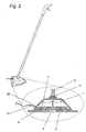
- Fig. 2 shows a cleaning device for cleaning floors and / or surfaces, comprising a container 1 'for receiving a cleaning liquid 2, a dispenser 3' for discharging the cleaning liquid to a floor and / or a surface to be cleaned and a heating device 4 'for heating and / or temperature control of the cleaning liquid 2.
- the heating device 4 ' is associated with a heat accumulator 5' which holds the cleaning fluid 2 alone or together with the heating device 4 'at a predeterminable operating temperature.
- the heating device 4 'and the heat accumulator 5' comprise phase change materials (PCM).
- PCM phase change materials
- the dispenser 3 ' is designed as a pump.
- the cleaning device has a removable handle or handle 11. By a power transmission device 12 cleaning fluid 2 can be pumped out of the container 1 '.
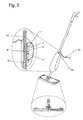
- Fig. 3 shows a further embodiment of a cleaning device for cleaning floors and / or surfaces.
- the cleaning device comprises a container 1 "for receiving a cleaning liquid 2, a dispensing device 3" for dispensing the cleaning liquid onto a floor and / or a surface to be cleaned and a heating device 4 "for heating and / or temperature control of the cleaning liquid 2.
- the heating device 4 may be assigned a heat accumulator 5", which holds the cleaning fluid 2 alone or together with the heating device at a predeterminable operating temperature.
- the delivery device 3 " is configured as a pump, and the pump is connected to a power transmission device 12 '.
- the heating device 4 "heats the cleaning fluid 2 to an operating temperature which is greater than 10 ° C. but less than 100 ° C. This also applies with respect to FIGS. 1 and 2 ,
- the heater 4 "and / or the heat storage 5" are wirelessly operable.
- the heater 4 " is operable by a battery 13.
- the heat accumulator 5 can comprise phase change materials, namely so-called” phase change materials "(PCM).
- the container 1" can be removed by the cleaning device.
- the heating device 4 "and / or heat storage 5" are integrated in the container 1 ".
- the cleaning device is designed as a mop.
- Fig. 3 shows in this respect a cleaning device, which shows a removable container 1 ", in which a battery is accommodated 13. As a result, a wireless operation is possible.
- the 4 to 6 show another cleaning device for cleaning floors and / or surfaces.
- This comprises a container 1 '"for receiving a cleaning liquid 2, a dispenser 3'" for dispensing the cleaning liquid 2 to a floor and / or a surface to be cleaned and a heater 4 '"for heating and / or temperature and / or evaporation of Cleaning fluid 2.
- the cleaning device can be operated wirelessly.
- a power cable 21 can be connected via an adapter 22 to the cleaning device and disconnected again for operation.
- the container 1 '"for receiving the cleaning liquid 2 is designed as a thermally insulated liquid tank in which the cleaning liquid 2 can be filled via a filling nozzle 1a' '.
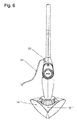
- Fig. 6 shows that the cleaning device has a frame 14 "', wherein in the frame 14'" an opening 15 '"is provided, through which the dispenser 3'" cleaning liquid 2 applied to the floor to be cleaned and / or the surface to be cleaned.
- the Fig. 4 and 5 show that a display device 16 '"is provided which indicates that an operating temperature of the cleaning liquid 2 has been reached.
- the display device 16'" is designed as a whistle. The whistle is placed near the dispenser 3 '"for the protection of the serving persons.
- a fill level indicator 17 '" is provided, which indicates the remaining amount of cleaning liquid 2.
- the fill level indicator 17'" comprises a float and a flag, which can be seen from the outside.
- a reheater element 23 may be provided which is assigned to the heating device 4 "or the delivery device 3 '" in order to evaporate the cleaning liquid 2.
- a metering device 24 may be provided which adds a substance to the cleaning fluid 2. This is in Fig. 5 shown.
- the dispenser 3 '" is operated by an actuator comprising a handle 3a'".
- the handle 3a '" preferably cooperates with a linkage which actuates the dispenser 3'".
- the handle 3a '" is pulled upwards.
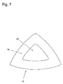
- Fig. 7 shows a cloth 18 for use on a cleaning device according to 4 to 6 , It comprises a flat base body 19, in which a hole 20 is formed. Through this hole 20, the cleaning liquid 2 can be applied to a floor and / or a surface to be cleaned.
- the cloth 18 has an outer borderline which essentially describes a triangle.
- the hole 20 is also substantially triangular.
- the cleaning liquid 2 water, alcohol, oil, surfactant and / or a mixture of the aforementioned substances can be used.
Landscapes
- Cleaning By Liquid Or Steam (AREA)
- Cleaning In General (AREA)
Abstract
Description
- Die Erfindung betrifft ein Reinigungsgerät gemäß dem Oberbegriff des Patentanspruchs 1.
- Aus dem Stand der Technik, beispielsweise der
DE 101 24 336 B4 , sind Reinigungsgeräte zur Reinigung von Böden und/oder Flächen bereits bekannt, die einen Behälter zur Aufnahme einer Reinigungsflüssigkeit aufweisen. Die Reinigungsflüssigkeit wird über eine Abgabeeinrichtung auf einen Boden und/oder eine zu reinigende Fläche übertragen. - Eine solche Abgabeeinrichtung kann als Düse ausgestaltet sein oder einen Schwamm bzw. ein Tuch umfassen, welcher bzw. welches durch Kapillarkräfte Reinigungsflüssigkeit auf den Boden und/oder die Fläche überträgt.
- Die aus dem Stand der Technik bekannten Reinigungsgeräte benötigen eine externe Energiequelle, um die Reinigungsflüssigkeit innerhalb des Behälters zu erwärmen und/oder zu temperieren. Oft ist ein Kabel vorgesehen, welches mit der externen Energiequelle verbunden ist. Die Handhabung solcher Reinigungsgeräte ist jedoch unkomfortabel und aufwendig.
- Der Erfindung liegt daher die Aufgabe zugrunde, ein Reinigungsgerät der eingangs genannten Art derart auszugestalten und weiterzubilden, dass dieses problemlos mit Energie zur Erwärmung und/oder Temperierung und/ oder Verdampfung der Reinigungsflüssigkeit versorgbar ist.
- Die vorliegende Erfindung löst die zuvor genannte Aufgabe durch die Merkmale des Patentanspruchs 1.
- Erfindungsgemäß ist erkannt worden, dass die Energie einer externen Energiequelle der Heizeinrichtung während eines Aufladezeitraums zuführbar ist, wobei das Reinigungsgerät selbst von der externen Energiequelle während eines Reinigungsvorgangs abkoppelbar ist. So kann das Reinigungsgerät erfindungsgemäß kabellos betrieben werden. Insoweit ist ein Reinigungsgerät derart ausgestaltet, dass dieses problemlos mit Energie zur Erwärmung und/oder Temperierung und/ oder Verdampfung der Reinigungsflüssigkeit versorgbar ist.
- Folglich ist die eingangs genannte Aufgabe gelöst.
- Der Heizeinrichtung könnte ein Wärmespeicher zugeordnet sein, welcher die Reinigungsflüssigkeit allein oder gemeinsam mit der Heizeinrichtung auf einer vorgebbaren Betriebstemperatur hält. Ein Wärmespeicher kann über längere Zeit Wärme an die Reinigungsflüssigkeit abgeben und diese auch dann noch auf einer geeigneten Betriebstemperatur halten, wenn eine externe Energiequelle nicht mehr zur Verfügung steht. Der Wärmespeicher stellt sicher, dass über einen sehr langen Zeitraum Wärme in definierter Weise an die Reinigungsflüssigkeit abgegeben wird, so dass diese in heißem oder warmem Zustand auf einen Boden und/oder eine zu reinigende Fläche abgegeben werden kann.
- Die Heizeinrichtung könnte die Reinigungsflüssigkeit auf eine Betriebstemperatur erhitzen, die größer als 10°C ist, jedoch unterhalb von 100°C liegt. Durch diese konkrete Ausgestaltung ist sichergestellt, dass innerhalb des Behälters keine hohen Drücke durch Dampfentwicklung entstehen. Bevorzugt wird eine Temperatur eingehalten, bei der eine Dampfentwicklung gerade noch nicht stattfindet. Hierdurch kann zwar heiße Reinigungsflüssigkeit auf Böden oder zu reinigende Flächen abgegeben werden, es bleibt jedoch sichergestellt, dass keine hohen Innendrücke innerhalb des Behälters entstehen, welche diesen beschädigen können. Insoweit wird die Siedetemperatur der Reinigungsflüssigkeit nicht erreicht, um Dampfentwicklung zu vermeiden.
- In einer bevorzugten Ausführungsform könnte die Heizeinrichtung die Reinigungsflüssigkeit auf eine Betriebstemperatur erhitzen, die größer 100 °C ist. Vorteilhaft kann durch erzeugten Dampf eine hohe Energie auf die zu reinigende Fläche aufgebracht werden. Die Abgabeeinrichtung kann konstruktiv sehr einfach, beispielsweise als Ventil, ausgestaltet sein. Bei dieser konkreten Ausgestaltung wird die Siedetemperatur der Reinigungsflüssigkeit erreicht, um eine Dampfentwicklung zu bewirken.
- Die Heizeinrichtung könnte als elektrische Widerstandsheizung ausgeführt sein. Vorteilhaft wird eine bekannte und störunanfällige Technologie zur Wärmeerzeugung genutzt.
- Die Heizeinrichtung könnte bei Erreichen einer vordefinierten Betriebstemperatur der Reinigungsflüssigkeit automatisch abschalten. Vor diesem Hintergrund ist denkbar, dass die Heizeinrichtung bei einer werksseitig definierten Betriebstemperatur automatisch abschaltet. Dies kann durch einen Thermostaten realisiert werden.
- Die Heizeinrichtung und/oder der Wärmespeicher könnten kabellos betreibbar sein. Durch diese konkrete Ausgestaltung kann das Reinigungsgerät unabhängig von einer externen Energiequelle bewegt und benutzt werden.
- Vor diesem Hintergrund könnte die Heizeinrichtung durch eine Batterie betreibbar sein. Eine Batterie kann durch eine externe Energiequelle während eines Aufladezeitraums aufgeladen werden. Nach dem Aufladen der Batterie kann diese über einen sehr langen Zeitraum Energie bereitstellen, mit welcher Reinigungsflüssigkeit erhitzt und/oder temperiert wird.
- Die Batterie könnte durch ein Ladegerät aufladbar sein, welches entweder im oder am Reinigungsgerät oder in oder an einer externen Ladestation aufgenommen ist. Vorteilhaft kann mit einem Ladegerät die Batterie schnell aufgeladen werden.
- Sowohl das Ladegerät als auch die Heizeinrichtung und/ oder der Wärmespeicher und/ oder die Reinigungsflüssigkeit könnten simultan mit Energie beaufschlagbar sein. Vorteilhaft kann der Benutzer das Reinigungsgerät zeitsparend und selbsterklärend in einen betriebstauglichen Zustand verbringen.
- Die Heizeinrichtung könnte durch eine Netzspannung betreibbar sein. Hierdurch kann problemlos eine sehr hohe Heizleistung zugeführt werden. Problemlos kann Strom aus der Steckdose genutzt werden. Hierdurch kann ein Kabel nur für einen gewissen Zeitraum genutzt werden, nämlich, um die Reinigungsflüssigkeit und/ oder den Wärmespeicher thermisch aufzuladen. Danach kann das Kabel vom Netz und/ oder vom Reinigungsgerät getrennt werden.
- Die Heizeinrichtung könnte durch flüssige, feste und/ oder gasförmige Brennstoffe betreibbar sein. Als solche Brennstoffe könnten Gas, Benzin, Öl, Trockenspiritus, Alkohol, Kohle, Holz und ähnliches verwendet werden. Vorteilhaft haben diese Brennstoffe einen hohen Energiegehalt. Des Weiteren ist das Reinigungsgerät bei Verwendung dieser Brennstoffe problemlos mobil einsetzbar.
- Der Wärmespeicher könnte Phasenwechselmaterialien, nämlich so genannte "phase change materials" (PCM) umfassen. Ein Beispiel für ein solches Material ist Paraffin. Diese Materialien zeigen eine besonders hohe Wärmespeicherkapazität. Beim Phasenübergang von fest nach flüssig zeigen diese Materialien definierte Temperaturbereiche, in denen Wärme zugeführt werden kann, ohne dass sich die Temperatur der Materialien ändert. Beim Abkühlen eines solchen Materials gibt dieses die gespeicherte Wärme an die Umgebung ab. Dieser Effekt kann genutzt werden, um die gespeicherte Wärme der Reinigungsflüssigkeit zuzuführen und so deren Abkühlung auf Umgebungstemperatur über einen gewissen Zeitraum zu kompensieren.
- Der Wärmespeicher könnte Stahl, Zink, Aluminium, Zucker oder Zinn umfassen. Diese Materialien weisen eine hohe Wärmespeicherkapazität auf.
- In einem bevorzugten Ausführungsbeispiel könnte der Wärmespeicher zumindest teilweise vom Behälter umgeben sein. Hierdurch kann die Wärme vom Wärmespeicher in alle Richtungen an die Reinigungsflüssigkeit abgegeben werden.
- Der Wärmespeicher könnte im Kontakt mit dem Behälter stehen. Beispielsweise kann der Wärmespeicher nur an einer Seite des Behälters anliegen. Vorteilhaft kann der Wärmespeicher leicht montiert und ausgewechselt werden. Vorzugsweise ist der Behälter isoliert.
- Der Behälter könnte vom Reinigungsgerät abnehmbar sein. Durch diese konkrete Ausgestaltung kann der Behälter mit Reinigungsflüssigkeit befüllt und dann wieder an das Reinigungsgerät angekoppelt werden.
- Die Heizeinrichtung und/ oder der Wärmespeicher könnten vom Reinigungsgerät abnehmbar sein. Hierdurch kann der Wärmespeicher vom Reinigungsgerät getrennt thermisch aufgeladen werden.
- Die Heizeinrichtung und/oder der Wärmespeicher könnten in den Behälter integriert sein. Durch diese konkrete Ausgestaltung kann die Heizeinrichtung und/oder der Wärmespeicher gemeinsam mit dem Behälter vom Reinigungsgerät entfernt werden.
- Sowohl die Heizeinrichtung als auch der Wärmespeicher könnten an eine externe Energiequelle angeschlossen werden. Nach einem Aufladevorgang kann der Behälter mit Reinigungsflüssigkeit befüllt werden. Vor diesem Hintergrund ist auch denkbar, dass der Behälter zunächst mit Reinigungsflüssigkeit befüllt und die Reinigungsflüssigkeit im Anschluss daran erhitzt wird. Der Behälter mit erhitzter Reinigungsflüssigkeit kann dann an das Reinigungsgerät angekoppelt werden. Die Reinigungsflüssigkeit wird dann durch die Heizeinrichtung und/ oder den Wärmespeicher unabhängig von einer externen Energiequelle weiter erhitzt oder in einem gewünschten Betriebstemperaturbereich gehalten.
- Das Reinigungsgerät könnte von einer Ladestation abtrennbar sein. Die Ladestation ermöglicht eine einfache Verbindung der Heizeinrichtung zu einer Energiequelle. Vor diesem Hintergrund ist denkbar, dass die Ladestation die Heizeinrichtung mit der Netzspannung eines Stromnetzes verbindet. Sobald die Heizeinrichtung und/ oder der Wärmespeicher und/ oder die Reinigungsflüssigkeit thermisch aufgeladen sind, kann das Reinigungsgerät von der Ladestation entnommen und kabellos mobil zur Reinigung verwendet werden. Im einfachsten Fall ist die Ladestation als trennbares Netzkabel ausgestaltet. Vor diesem Hintergrund ist denkbar, dass am Reinigungsgerät ein Adapter für das Netzkabel vorgesehen ist.
- Die Abgabeeinrichtung könnte gegen die Umgebung thermisch isoliert sein. Vorteilhaft wird hierdurch verhindert, dass die Temperatur der Reinigungsflüssigkeit in unerwünschtem Maße absinkt.
- Vor diesem Hintergrund könnte die Abgabeeinrichtung beheizbar ausgeführt sein. Durch eine Heizung kann die Reinigungsflüssigkeit auf einer gewünschten Temperatur gehalten werden.
- Die Abgabeeinrichtung könnte mechanisch, pneumatisch, hydraulisch und/ oder elektrisch betreibbar sein. Vor diesem Hintergrund ist denkbar, Pumpen, CO2-Patronen oder Druckbehälter zu verwenden. Weiter ist denkbar, die Schwerkraft zu nutzen, um die Reinigungsflüssigkeit auf die zu reinigenden Flächen zu fördern. Es könnte Ultraschall zur Förderung der Reinigungsflüssigkeit genutzt werden. Darüber hinaus könnte Ultraschall genutzt werden, um die Reinigungsflüssigkeit fein zu zerstäuben oder in Tröpfchen zu dispergieren.
- Die Abgabeeinrichtung könnte durch eine Betätigungseinrichtung bedient werden, die einen Griff umfasst. Der Griff wirkt vorzugsweise mit einem Gestänge zusammen, welches die Abgabeeinrichtung betätigt.
- Der Behälter zur Aufnahme der Reinigungsflüssigkeit könnte als thermisch isolierter Flüssigkeitstank ausgebildet sein. Hierdurch wird die Reinigungsflüssigkeit möglichst lange auf Betriebstemperatur gehalten.
- Das Reinigungsgerät könnte einen Rahmen aufweisen, wobei im Rahmen eine Öffnung vorgesehen ist, durch welche die Abgabeeinrichtung Reinigungsflüssigkeit auf den zu reinigenden Boden und/ oder die zu reinigende Fläche aufbringt. Durch den Rahmen kann ein Textil aufgespannt werden, um die Reinigungsflüssigkeit aufzunehmen oder zu verteilen.
- Das Reinigungsgerät könnte eine Anzeigeeinrichtung aufweisen, welche anzeigt, dass eine Betriebstemperatur der Reinigungsflüssigkeit erreicht ist. Hierdurch kann die bedienende Person leicht erkennen, dass das Reinigungsgerät einsatzbereit ist. Die Anzeigeeinrichtung könnte optische oder akustische Signale erzeugen.
- Die Anzeigeeinrichtung könnte als Pfeife ausgebildet sein. Eine Pfeife erzeugt nach Art eines Teekessels ein lautes leicht hörbares Signal.
- Die Pfeife könnte in der Nähe der Abgabeeinrichtung angeordnet sein. Hierdurch ist sicher gestellt, dass austretende Flüssigkeit oder Dampf den Benutzer nicht verletzt.
- Das Reinigungsgerät könnte einen Füllstandsanzeiger aufweisen, welcher die noch vorhandene Menge an Reinigungsflüssigkeit angibt. Hierdurch kann die bedienende Person leicht erkennen, ob das Reinigungsgerät einsatzbereit ist. Das Reinigungsgerät könnte ein Nacherhitzerelement aufweisen, welches der Heizeinrichtung oder der Abgabeeinrichtung zugeordnet ist, um die Reinigungsflüssigkeit zu verdampfen. Hierdurch kann die Reinigungsflüssigkeit im Flüssigkeitstank auf eine erste Temperatur verbracht werden und erst kurz vor Austritt aus der Abgabeeinrichtung auf die Endtemperatur verbracht und verdampft werden. So kann Energie gespart werden. Als Nacherhitzerelement kann beispielsweise ein Durchlauferhitzer verwendet werden.
- Das Reinigungsgerät könnte eine Dosiereinrichtung aufweisen, welche der Reinigungsflüssigkeit einen Stoff zugibt. Durch diese Maßnahme können temperaturempfindliche Reinigungs- oder Desinfektionsstoffe der Reinigungsflüssigkeit erst kurz vor deren Austritt aus der Abgabeeinrichtung beigemengt werden. Die Dosiereinrichtung ist bevorzugt zwischen Abgabeeinrichtung und Flüssigkeitstank, aber stets in Fließrichtung nach dem Flüssigkeitstank positioniert.
- Das Reinigungsgerät ist vorzugsweise als Wischmopp ausgestaltet. Ein Wischmopp kann mit Schwämmen, Textilien und/oder Düsen ausgestattet sein, welche die Reinigungsflüssigkeit aus dem Behälter dem Boden und/oder der zu reinigenden Fläche zuführen.
- Das Reinigungsgerät könnte ein autonomer Reinigungsroboter sein. Ein solcher Roboter kann selbständig auf zu reinigenden Flächen verfahren und diese reinigen.
- Die Reinigungsflüssigkeit des Reinigungsroboters könnte an einer Andockstation erhitzt werden. Des Weiteren kann an der Andockstation ein Akkumulator des Reinigungsroboters aufgeladen werden, welcher die Reinigungsflüssigkeit während der Fahrt des Reinigungsroboters temperiert oder verdampft. Vorzugsweise erzeugt der Reinigungsroboter Dampf, während er fährt. Sobald der Akkumulator leer ist, kehrt der Reinigungsroboter an die Andockstation zurück, um diesen aufzuladen. Vor diesem Hintergrund ist auch denkbar, dass der Reinigungsroboter an der Andockstation heiße Reinigungsflüssigkeit aus einem stationären Reservoir aufnimmt.
- Ein Tuch zur Verwendung an einem Reinigungsgerät der hier beschriebenen. Art könnte einen flächigen Grundkörper umfassen, in welchem ein Loch ausgebildet ist. Das Tuch kann auf einen Rahmen aufgespannt werden, wobei im Rahmen eine Öffnung vorgesehen ist, durch welche die Abgabeeinrichtung Reinigungsflüssigkeit auf den zu reinigenden Boden und/ oder die zu reinigende Fläche aufbringt. Da auch im Tuch ein Loch vorgesehen ist, welches mit der Öffnung im Rahmen weitgehend fluchtet, kann die Reinigungsflüssigkeit auf den zu reinigenden Boden und/ oder die zu reinigende Fläche unmittelbar aufgebracht und mit dem Tuch verteilt werden. Ferner kann mit dem Tuch eine Abrasivwirkung auf hartnäckigen Schmutz ausgeübt werden.
- Desweiteren könnte das Loch in dem textilen Grundkörper mit einer flexiblen, netzartigen Struktur abgedeckt sein. Dadurch kann Reinigungsflüssigkeit auf den zu reinigenden Boden aufgetragen werden und gleichzeitig kann durch die netzartige Struktur eine abrasive Reinigungswirkung ausgeübt werden.
- Das Tuch kann auch ohne Loch gefertigt sein.
- In der Zeichnung zeigen
- Fig. 1
- eine schematische Ansicht eines Behälters, dem ein Wärmespeicher zugeordnet ist, welcher durch eine Heizspirale temperierbar ist,
- Fig. 2
- ein weiteres Ausführungsbeispiel eines Reinigungsgeräts, bei welchem der Wärmespeicher Phasenwechselmaterialien (PCM) umfasst,
- Fig. 3
- ein weiteres Ausführungsbeispiel eines Reinigungsgeräts, bei welchem eine Batterie in den Behälter integriert ist, wobei der Behälter gemeinsam mit der Batterie vom Reinigungsgerät abkoppelbar ist,
- Fig. 4
- eine Schnittzeichnung eines Reinigungsgeräts, bei welchem in einem Flüssigkeitstank eine Heizeinrichtung in Form eines Tauchsieders mit einer Heizspirale aufgenommen ist,
- Fig. 5
- eine weitere Schnittansicht des Reinigungsgeräts gemäß
Fig. 4 , wobei der Griff der Betätigungseinrichtung für die Abgabeeinrichtung nach oben gezogen ist, - Fig. 6
- eine Vorderansicht des Reinigungsgeräts gemäß
Fig. 4 und5 , wobei dargestellt ist, dass im Rahmen eine Öffnung ausgebildet ist, und - Fig. 7
- eine Ansicht eines Tuchs mit einem im Wesentlichen dreieckförmigen Loch, wobei das Tuch ausgebildet ist, um vom Rahmen gemäß
Fig. 6 getragen zu werden. -
Fig. 1 zeigt einen Behälter 1 zur Aufnahme einer Reinigungsflüssigkeit 2, welcher einem Reinigungsgerät zur Reinigung von Böden und/oder Flächen zuordenbar ist. - Der Behälter weist eine Abgabeeinrichtung 3 zur Abgabe der Reinigungsflüssigkeit auf einen Boden und/oder eine zu reinigende Fläche auf. Die Abgabeeinrichtung 3 ist als Sprühdüse ausgestaltet.
- Der Behälter 1 weist des Weiteren eine Heizeinrichtung 4 zur Erwärmung und/oder Temperierung der Reinigungsflüssigkeit 2 auf.
- Die Heizeinrichtung 4 umfasst einen ersten Heizspiralenabschnitt 5 zur Erhitzung der Reinigungsflüssigkeit 2, welche sich innerhalb eines Tanks 6 befindet. Die Heizeinrichtung 4 weist des Weiteren einen zweiten Heizspiralenabschnitt 7 auf, welcher innerhalb eines Wärmespeichers 8 aufgenommen ist.
- Der Wärmespeicher 8 ist innerhalb des Tanks 6 aufgenommen und kann so Wärme rundum an die Reinigungsflüssigkeit 2 abgeben. Vorzugsweise ist der Tank 6 gegen die Atmosphäre oder Umgebung thermisch isoliert.
- Der Behälter 1 weist eine Einrichtung 9 zur Befüllung des Behälters 1 auf. Der Behälter 1 weist des Weiteren eine Einrichtung 10 zur Ankopplung des Behälters 1 an ein Reinigungsgerät auf.
-
Fig. 2 zeigt ein Reinigungsgerät zur Reinigung von Böden und/oder Flächen, umfassend einen Behälter 1' zur Aufnahme einer Reinigungsflüssigkeit 2, eine Abgabeeinrichtung 3' zur Abgabe der Reinigungsflüssigkeit auf einen Boden und/oder eine zu reinigende Fläche und eine Heizeinrichtung 4' zur Erwärmung und/oder Temperierung der Reinigungsflüssigkeit 2. - Der Heizeinrichtung 4' ist ein Wärmespeicher 5' zugeordnet, welcher die Reinigungsflüssigkeit 2 allein oder gemeinsam mit der Heizeinrichtung 4' auf einer vorgebbaren Betriebstemperatur hält.
- Die Heizeinrichtung 4' sowie der Wärmespeicher 5' umfassen Phasenwechselmaterialien (PCM).
- Die Abgabeeinrichtung 3' ist als Pumpe ausgestaltet. Das Reinigungsgerät weist einen abnehmbaren Stiel oder Griff 11 auf. Durch eine Kraftübertragungseinrichtung 12 kann Reinigungsflüssigkeit 2 aus dem Behälter 1' gepumpt werden.
-
Fig. 3 zeigt ein weiteres Ausführungsbeispiel eines Reinigungsgeräts zur Reinigung von Böden und/oder Flächen. Das Reinigungsgerät umfasst einen Behälter 1" zur Aufnahme einer Reinigungsflüssigkeit 2, eine Abgabeeinrichtung 3" zur Abgabe der Reinigungsflüssigkeit auf einen Boden und/oder eine zu reinigende Fläche und eine Heizeinrichtung 4" zur Erwärmung und/oder Temperierung der Reinigungsflüssigkeit 2. - Der Heizeinrichtung 4" kann ein Wärmespeicher 5" zugeordnet sein, welcher die Reinigungsflüssigkeit 2 allein oder gemeinsam mit der Heizeinrichtung auf einer vorgebbaren Betriebstemperatur hält.
- Die Abgabeeinrichtung 3" ist als Pumpe ausgestaltet. Die Pumpe ist mit einer Kraftübertragungseinrichtung 12' verbunden.
- Die Heizeinrichtung 4" erhitzt die Reinigungsflüssigkeit 2 auf eine Betriebstemperatur, die größer als 10 °C ist, jedoch unterhalb von 100 °C liegt. Dies gilt auch in Bezug auf die
Figuren 1 und2 . - Die Heizeinrichtung 4" und/oder der Wärmespeicher 5" sind kabellos betreibbar. Die Heizeinrichtung 4" ist durch eine Batterie 13 betreibbar.
- Der Wärmespeicher 5" kann Phasenwechselmaterialien umfassen, nämlich so genannte "phase change materials" (PCM). Der Behälter 1" ist vom Reinigungsgerät abnehmbar. Die Heizeinrichtung 4" und/oder Wärmespeicher 5" sind in den Behälter 1" integriert.
- Das Reinigungsgerät ist als Wischmopp ausgestaltet.
-
Fig. 3 zeigt insoweit ein Reinigungsgerät, welches einen abnehmbaren Behälter 1" zeigt, in welchem eine Batterie 13 aufgenommen ist. Hierdurch ist ein kabelloser Betrieb möglich. - Die
Fig. 4 bis 6 zeigen ein weiteres Reinigungsgerät zur Reinigung von Böden und/ oder Flächen. - Dieses umfasst einen Behälter 1'" zur Aufnahme einer Reinigungsflüssigkeit 2, eine Abgabeeinrichtung 3'" zur Abgabe der Reinigungsflüssigkeit 2 auf einen Boden und/ oder eine zu reinigende Fläche und eine Heizeinrichtung 4'" zur Erwärmung und/ oder Temperierung und/ oder Verdampfung der Reinigungsflüssigkeit 2. Das Reinigungsgerät ist kabellos betreibbar.
- Ein Netzkabel 21 kann über einen Adapter 22 mit dem Reinigungsgerät verbunden und zum Betrieb wieder getrennt werden.
- Der Behälter 1'" zur Aufnahme der Reinigungsflüssigkeit 2 ist als thermisch isolierter Flüssigkeitstank ausgebildet. In diesen ist die Reinigungsflüssigkeit 2 über einen Befüllstutzen 1a"` einfüllbar.
-
Fig. 6 zeigt, dass das Reinigungsgerät einen Rahmen 14"' aufweist, wobei im Rahmen 14'" eine Öffnung 15'" vorgesehen ist, durch welche die Abgabeeinrichtung 3'" Reinigungsflüssigkeit 2 auf den zu reinigenden Boden und/ oder die zu reinigende Fläche aufbringt. - Die
Fig. 4 und5 zeigen, dass eine Anzeigeeinrichtung 16'" vorgesehen ist, welche anzeigt, dass eine Betriebstemperatur der Reinigungsflüssigkeit 2 erreicht ist. Die Anzeigeeinrichtung 16'" ist als Pfeife ausgebildet. Die Pfeife ist zum Schutz der bedienenden Personen in der Nähe der Abgabeeinrichtung 3'" angeordnet. - Des Weiteren ist ein Füllstandsanzeiger 17'" vorgesehen, welcher die noch vorhandene Menge an Reinigungsflüssigkeit 2 angibt. Der Füllstandsanzeiger 17'" umfasst einen Schwimmer und ein Fähnchen, welches von außen erkennbar ist.
- Weiter kann ein Nacherhitzerelement 23 vorgesehen sein, welches der Heizeinrichtung 4"` oder der Abgabeeinrichtung 3'" zugeordnet ist, um die Reinigungsflüssigkeit 2 zu verdampfen. Schließlich kann eine Dosiereinrichtung 24 vorgesehen sein, welche der Reinigungsflüssigkeit 2 einen Stoff zugibt. Dies ist in
Fig. 5 dargestellt. - Die Abgabeeinrichtung 3'" wird durch eine Betätigungseinrichtung bedient, die einen Griff 3a'" umfasst. Der Griff 3a'" wirkt vorzugsweise mit einem Gestänge zusammen, welches die Abgabeeinrichtung 3'" betätigt. In
Fig. 5 ist der Griff 3a'" nach oben gezogen. -
Fig. 7 zeigt ein Tuch 18 zur Verwendung an einem Reinigungsgerät gemäßFig. 4 bis 6 . Es umfasst einen flächigen Grundkörper 19, in welchem ein Loch 20 ausgebildet ist. Durch dieses Loch 20 kann die Reinigungsflüssigkeit 2 auf einen Boden und/ oder eine zu reinigende Fläche aufgebracht werden. Das Tuch 18 weist eine äußere Umrandungslinie auf, welche im Wesentlichen ein Dreieck beschreibt. Das Loch 20 ist ebenfalls im Wesentlichen dreieckförmig. - Als Reinigungsflüssigkeit 2 kann Wasser, Alkohol, Öl, Tensid und/ oder eine Mischung aus den vorgenannten Stoffen verwendet werden.
Claims (5)
- Reinigungsgerät zur Reinigung von Böden und/ oder Flächen, umfassend einen Behälter (1, 1', 1", 1"') zur Aufnahme einer Reinigungsflüssigkeit (2), eine Abgabeeinrichtung (3, 3`, 3", 3"') zur Abgabe der Reinigungsflüssigkeit (2) auf einen Boden und/ oder eine zu reinigende Fläche und eine Heizeinrichtung (4, 4', 4", 4'") zur Erwärmung und/ oder Temperierung und/ oder Verdampfung der Reinigungsflüssigkeit (2),
dadurch gekennzeichnet, dass das Reinigungsgerät kabellos betreibbar ist. - Reinigungsgerät nach Anspruch 1, dadurch gekennzeichnet, dass die Abgabeeinrichtung (3, 3', 3", 3"') gegen die Umgebung thermisch isoliert ist.
- Reinigungsgerät nach einem der voranstehenden Ansprüche, dadurch gekennzeichnet, dass die Abgabeeinrichtung (3, 3', 3", 3"') beheizbar ausgeführt ist.
- Reinigungsgerät nach einem der voranstehenden Ansprüche,
gekennzeichnet durch ein Nacherhitzerelement (23), welches der Heizeinrichtung (4"') oder der Abgabeeinrichtung (3"') zugeordnet ist, um die Reinigungsflüssigkeit (2) zu verdampfen. - Reinigungsgerät nach einem der voranstehenden Ansprüche,
gekennzeichnet durch eine Ausgestaltung als autonomer Reinigungsroboter.
Priority Applications (1)
| Application Number | Priority Date | Filing Date | Title |
|---|---|---|---|
| PL16152396T PL3040009T3 (pl) | 2012-12-13 | 2013-09-26 | Sprzęt czyszczący ze zbiornikiem na płyn |
Applications Claiming Priority (4)
| Application Number | Priority Date | Filing Date | Title |
|---|---|---|---|
| DE102012024356 | 2012-12-13 | ||
| DE102013014024 | 2013-08-26 | ||
| EP13786159.7A EP2931106B1 (de) | 2012-12-13 | 2013-09-26 | Reinigungsgerät mit einem flüssigkeitsbehälter |
| PCT/EP2013/002884 WO2014090350A2 (de) | 2012-12-13 | 2013-09-26 | Reinigungsgerät mit einem flüssigkeitsbehälter |
Related Parent Applications (2)
| Application Number | Title | Priority Date | Filing Date |
|---|---|---|---|
| EP13786159.7A Division EP2931106B1 (de) | 2012-12-13 | 2013-09-26 | Reinigungsgerät mit einem flüssigkeitsbehälter |
| EP13786159.7A Division-Into EP2931106B1 (de) | 2012-12-13 | 2013-09-26 | Reinigungsgerät mit einem flüssigkeitsbehälter |
Publications (3)
| Publication Number | Publication Date |
|---|---|
| EP3040009A2 true EP3040009A2 (de) | 2016-07-06 |
| EP3040009A3 EP3040009A3 (de) | 2016-09-07 |
| EP3040009B1 EP3040009B1 (de) | 2021-11-03 |
Family
ID=49518907
Family Applications (2)
| Application Number | Title | Priority Date | Filing Date |
|---|---|---|---|
| EP16152396.4A Active EP3040009B1 (de) | 2012-12-13 | 2013-09-26 | Reinigungsgerät mit einem flüssigkeitsbehälter |
| EP13786159.7A Active EP2931106B1 (de) | 2012-12-13 | 2013-09-26 | Reinigungsgerät mit einem flüssigkeitsbehälter |
Family Applications After (1)
| Application Number | Title | Priority Date | Filing Date |
|---|---|---|---|
| EP13786159.7A Active EP2931106B1 (de) | 2012-12-13 | 2013-09-26 | Reinigungsgerät mit einem flüssigkeitsbehälter |
Country Status (10)
| Country | Link |
|---|---|
| US (1) | US9962057B2 (de) |
| EP (2) | EP3040009B1 (de) |
| CN (1) | CN104853663A (de) |
| AU (1) | AU2013357890B2 (de) |
| CA (1) | CA2893297C (de) |
| ES (2) | ES2899898T3 (de) |
| PL (2) | PL2931106T3 (de) |
| PT (1) | PT2931106T (de) |
| SI (1) | SI2931106T1 (de) |
| WO (1) | WO2014090350A2 (de) |
Cited By (1)
| Publication number | Priority date | Publication date | Assignee | Title |
|---|---|---|---|---|
| WO2021043772A1 (de) * | 2019-09-05 | 2021-03-11 | Henkel Ag & Co. Kgaa | Reinigungsroboter umfassend ein reinigungstuch und ein reinigungsmittel |
Families Citing this family (27)
| Publication number | Priority date | Publication date | Assignee | Title |
|---|---|---|---|---|
| ITTV20120106A1 (it) * | 2012-05-31 | 2013-12-01 | Pier Antonio Milanese | Sistema per la pulizia a caldo delle superfici |
| US9877631B2 (en) * | 2015-06-26 | 2018-01-30 | Unger Marketing International, Llc | Hard surface cleaning devices |
| US10973387B2 (en) | 2015-06-26 | 2021-04-13 | Unger Marketing International, Llc | Multi-orientation cleaning device |
| CN105499167A (zh) * | 2015-11-25 | 2016-04-20 | 重庆垠庚生态农业发展有限公司 | 一种自带清洁剂的清洁用具 |
| CN105396804A (zh) * | 2015-11-25 | 2016-03-16 | 重庆垠庚生态农业发展有限公司 | 一种养殖场专用清洁工具 |
| CN105396805A (zh) * | 2015-11-25 | 2016-03-16 | 重庆垠庚生态农业发展有限公司 | 一种养殖场专用清洁器 |
| CN105478382A (zh) * | 2015-11-25 | 2016-04-13 | 重庆垠庚生态农业发展有限公司 | 一种清洁工具 |
| CN105361831A (zh) * | 2015-11-25 | 2016-03-02 | 重庆垠庚生态农业发展有限公司 | 一种清洁器 |
| CN105361830A (zh) * | 2015-11-25 | 2016-03-02 | 重庆垠庚生态农业发展有限公司 | 一种新型清洁器 |
| CN105396806A (zh) * | 2015-11-25 | 2016-03-16 | 重庆垠庚生态农业发展有限公司 | 一种养殖场专用清洁用具 |
| KR101769232B1 (ko) | 2016-01-14 | 2017-08-17 | 엘지전자 주식회사 | 청소기 및 물 청소기구 |
| KR102401781B1 (ko) * | 2016-01-19 | 2022-05-26 | 엘지전자 주식회사 | 청소기 |
| CN105816121A (zh) * | 2016-06-03 | 2016-08-03 | 江苏纽唯盛机电有限公司 | 一种无线蒸汽拖把及其使用方法 |
| DE202017104994U1 (de) * | 2016-08-31 | 2017-09-18 | Jiaxing Jackson Travel Products Co., Ltd. | Spray-Mopp |
| EP3512400B1 (de) * | 2016-09-14 | 2026-01-14 | Unger Marketing International, LLC | Reinigungsvorrichtungen für harte oberflächen |
| USD840625S1 (en) | 2016-09-14 | 2019-02-12 | Unger Marketing International, Llc | Hard surface cleaning device |
| USD840626S1 (en) | 2016-09-14 | 2019-02-12 | Unger Marketing International, Llc | Hard surface cleaning device |
| USD848093S1 (en) | 2016-10-17 | 2019-05-07 | Unger Marketing International, Llc | Hard surface cleaning device |
| USD850883S1 (en) | 2016-10-17 | 2019-06-11 | Unger Marketing International, Llc | Tool handle |
| WO2018103052A1 (zh) * | 2016-12-08 | 2018-06-14 | 凯灿贸易(深圳)有限公司 | 一种蒸汽拖把 |
| US10813523B2 (en) * | 2017-02-01 | 2020-10-27 | Infiniti Cleaning Solutions, LLC. | Mop with advancing cleaning fabric material |
| USD904704S1 (en) | 2018-03-14 | 2020-12-08 | Unger Marketing International, Llc | Hard surface cleaning device |
| FR3086190B1 (fr) * | 2018-09-21 | 2020-10-30 | Ningbo Ecodrop Electric Tech Co Ltd | Appareil de nettoyage de surfaces |
| USD1009394S1 (en) * | 2021-02-10 | 2023-12-26 | Carl Freudenberg Kg | Floor mop |
| CN113243850A (zh) * | 2021-02-10 | 2021-08-13 | 北京顺造科技有限公司 | 基站和表面清洁设备的通信方法及存储介质 |
| CN114601382B (zh) * | 2022-03-08 | 2023-10-10 | 云鲸智能(深圳)有限公司 | 基站的控制方法、清洁装置和存储介质 |
| USD1072402S1 (en) * | 2023-02-14 | 2025-04-22 | Carl Freudenberg Kg | Cleaning device |
Citations (1)
| Publication number | Priority date | Publication date | Assignee | Title |
|---|---|---|---|---|
| DE10124336B4 (de) | 2001-05-18 | 2009-04-02 | Carl Freudenberg Kg | Vorrichtung zum Wischen und Reinigen von verschmutzten Oberflächen |
Family Cites Families (31)
| Publication number | Priority date | Publication date | Assignee | Title |
|---|---|---|---|---|
| ITGE960041U1 (it) * | 1996-11-13 | 1998-05-13 | Ariete Srl | Apparecchio pulitore a vapore. |
| US6131237A (en) * | 1997-07-09 | 2000-10-17 | Bissell Homecare, Inc. | Upright extraction cleaning machine |
| US6571421B1 (en) * | 2000-10-03 | 2003-06-03 | John Chun Kuen Sham | Vacuum cleaner and steamer apparatus |
| US6584990B2 (en) * | 2001-01-19 | 2003-07-01 | Dervin International Pty. Ltd. | Steam mop |
| US20030089383A1 (en) * | 2001-11-13 | 2003-05-15 | Biggs Blyth S. | Egronomic sprayer mop and method |
| JP4098750B2 (ja) * | 2004-06-03 | 2008-06-11 | ユニ・チャーム株式会社 | 噴液装置を備えた清掃具 |
| GB0412681D0 (en) * | 2004-06-08 | 2004-07-07 | Reckitt Benckiser Nv | Cleaning device |
| ES2346343T3 (es) * | 2005-02-18 | 2010-10-14 | Irobot Corporation | Robot autonomo de limpieza de superficies para una limpieza en seco y en mojado. |
| WO2006091509A2 (en) | 2005-02-22 | 2006-08-31 | Royal Appliance Mfg. Co. | High pressure extractor |
| US7811022B2 (en) * | 2005-06-29 | 2010-10-12 | Electrolux Home Care Products, Inc. | Flexible floor cleaning device |
| US7774894B2 (en) * | 2005-10-11 | 2010-08-17 | Kimberly-Clark Worldwide, Inc. | Micro powered floor cleaning device |
| US20070133962A1 (en) * | 2005-10-19 | 2007-06-14 | Rizzuto Leandro P | Cordless steam cleaner |
| KR100662440B1 (ko) * | 2005-12-09 | 2007-01-02 | 엘지전자 주식회사 | 스팀 청소기 |
| CN2894596Y (zh) * | 2005-12-10 | 2007-05-02 | 小田(中山)实业有限公司 | 一种蒸汽地刷 |
| KR100745593B1 (ko) | 2006-03-06 | 2007-08-03 | 삼성광주전자 주식회사 | 스팀 발생장치 |
| US20070231046A1 (en) | 2006-03-14 | 2007-10-04 | Eastway Fair Company Limited | Cleaning device having heated cleaning solution |
| WO2008007830A1 (en) | 2006-07-14 | 2008-01-17 | Hanulkid Co., Ltd. | Steam robot cleaner |
| CN102083352B (zh) * | 2008-04-24 | 2014-10-15 | 艾罗伯特公司 | 用于机器人使能的移动产品的定位、位置控制和导航系统的应用 |
| US8534301B2 (en) * | 2008-06-02 | 2013-09-17 | Innovation Direct Llc | Steam mop |
| US20090313767A1 (en) * | 2008-06-22 | 2009-12-24 | Antimicrobial Test Laboratories, Llc | Cordless Battery Operated Handheld Steamer and Methods of Operation |
| CN201263661Y (zh) | 2008-08-19 | 2009-07-01 | 肖威 | 一种蒸汽地板清洁机 |
| CN201324218Y (zh) | 2008-11-17 | 2009-10-14 | 小田(中山)实业有限公司 | 一种蒸汽拖把 |
| US8927480B2 (en) * | 2010-12-14 | 2015-01-06 | Bissell Homecare, Inc. | Cleaning cloth with encapsulated formulation, steam mop and method |
| CN201996475U (zh) * | 2011-01-30 | 2011-10-05 | 欧福莱有限责任公司 | 清洁布、蒸汽地拖、拖把、清洁机 |
| CN103547202B (zh) * | 2011-02-16 | 2016-06-08 | 创科地板护理技术有限公司 | 包括擦拭垫的表面清洁器 |
| JP2012200385A (ja) | 2011-03-25 | 2012-10-22 | Panasonic Corp | 電気掃除機 |
| CN202235207U (zh) | 2011-06-27 | 2012-05-30 | 佛山市顺德区盛熙电器制造有限公司 | 地拖 |
| US20130091647A1 (en) * | 2011-10-14 | 2013-04-18 | Kwang-Tong YUAN | Self-feeding steam mop |
| US9420933B2 (en) * | 2011-12-12 | 2016-08-23 | Bissell Homecare, Inc. | Surface cleaning apparatus |
| US20140041147A1 (en) * | 2012-08-10 | 2014-02-13 | Chad Pagoria | Surface cleaner including forward-facing liquid tanks |
| US10004373B2 (en) * | 2012-09-17 | 2018-06-26 | Bissell Homecare, Inc. | Cleaning pad with visually discernible indicator, steam mop and method |
-
2013
- 2013-09-26 PL PL13786159T patent/PL2931106T3/pl unknown
- 2013-09-26 CA CA2893297A patent/CA2893297C/en active Active
- 2013-09-26 PL PL16152396T patent/PL3040009T3/pl unknown
- 2013-09-26 AU AU2013357890A patent/AU2013357890B2/en not_active Ceased
- 2013-09-26 WO PCT/EP2013/002884 patent/WO2014090350A2/de not_active Ceased
- 2013-09-26 SI SI201330680T patent/SI2931106T1/sl unknown
- 2013-09-26 CN CN201380065163.1A patent/CN104853663A/zh active Pending
- 2013-09-26 EP EP16152396.4A patent/EP3040009B1/de active Active
- 2013-09-26 US US14/651,675 patent/US9962057B2/en active Active
- 2013-09-26 ES ES16152396T patent/ES2899898T3/es active Active
- 2013-09-26 EP EP13786159.7A patent/EP2931106B1/de active Active
- 2013-09-26 ES ES13786159.7T patent/ES2626495T3/es active Active
- 2013-09-26 PT PT137861597T patent/PT2931106T/pt unknown
Patent Citations (1)
| Publication number | Priority date | Publication date | Assignee | Title |
|---|---|---|---|---|
| DE10124336B4 (de) | 2001-05-18 | 2009-04-02 | Carl Freudenberg Kg | Vorrichtung zum Wischen und Reinigen von verschmutzten Oberflächen |
Cited By (2)
| Publication number | Priority date | Publication date | Assignee | Title |
|---|---|---|---|---|
| WO2021043772A1 (de) * | 2019-09-05 | 2021-03-11 | Henkel Ag & Co. Kgaa | Reinigungsroboter umfassend ein reinigungstuch und ein reinigungsmittel |
| US12089792B2 (en) | 2019-09-05 | 2024-09-17 | Henkel Ag & Co. Kgaa | Cleaning robot comprising a cleaning cloth and a cleaning agent |
Also Published As
| Publication number | Publication date |
|---|---|
| US9962057B2 (en) | 2018-05-08 |
| US20150305588A1 (en) | 2015-10-29 |
| PT2931106T (pt) | 2017-06-05 |
| WO2014090350A3 (de) | 2014-07-31 |
| PL3040009T3 (pl) | 2022-03-07 |
| EP2931106A2 (de) | 2015-10-21 |
| CA2893297C (en) | 2019-02-05 |
| AU2013357890A1 (en) | 2015-06-04 |
| CA2893297A1 (en) | 2014-06-19 |
| SI2931106T1 (sl) | 2017-08-31 |
| EP3040009B1 (de) | 2021-11-03 |
| ES2899898T3 (es) | 2022-03-15 |
| AU2013357890B2 (en) | 2017-01-19 |
| EP2931106B1 (de) | 2017-04-12 |
| CN104853663A (zh) | 2015-08-19 |
| EP3040009A3 (de) | 2016-09-07 |
| PL2931106T3 (pl) | 2017-09-29 |
| ES2626495T3 (es) | 2017-07-25 |
| WO2014090350A2 (de) | 2014-06-19 |
Similar Documents
| Publication | Publication Date | Title |
|---|---|---|
| EP2931106B1 (de) | Reinigungsgerät mit einem flüssigkeitsbehälter | |
| EP2363051B2 (de) | Kaffeemaschine und Verfahren zur Reinigung derselben | |
| EP2160125B1 (de) | Bodenreinigungsgerät mit reinigungsflüssigkeitsbehälter und schmutzflüssigkeitsbehälter | |
| EP2237900B1 (de) | Hochdruckreinigungsgerät mit einem system zur bevorratung und abgabe von flüssigem reinigungszusatz | |
| DE202017100687U1 (de) | Oberflächenreinigungsgerät | |
| DE102018114476B3 (de) | Reinigungssystem, umfassend Versorgungsroboter und Reinigungssatelliten, und Verfahren zur Reinigung | |
| EP2705784B1 (de) | Getränkebereiter | |
| WO2018108237A1 (de) | Mobiles dekontaminationssystem | |
| WO2011082830A1 (de) | Bodenreinigungsgerät | |
| EP2259694A1 (de) | Haarentfernungsgerät | |
| DE202009001542U1 (de) | Fahrbarer Milchbehälter für die Nutztieraufzucht | |
| DE202012012925U1 (de) | Dungentfernungsvorrichtung | |
| DE202005012843U1 (de) | Milchwagen für die Nutztieraufzucht | |
| DE102014014971B4 (de) | Handspritze | |
| EP3442716A1 (de) | Vorrichtung zum unterdrucksetzen und abgeben einer reinigungsflüssigkeit | |
| DE102015011464A1 (de) | Tuchspendevorrichtung für einen Kraftwagen | |
| DE102007057156A1 (de) | Verfahren und Vorrichtung zum Reinigen von Goldzubehör | |
| CH704800A2 (de) | Vorrichtung zur Beseitigung von Eis und Schnee auf oder an Objekten. | |
| DE202012008778U1 (de) | Haltevorrichtung für einen handgeführten Schäumer | |
| DE2451755C3 (de) | Einrichtung zur Befeuchtung von Abschnitten eines saugfähigen Trägers | |
| DE200657C (de) | ||
| DE3618598C2 (de) | ||
| DE102014110133B4 (de) | Verfahren zum Schutz eines Hochdruckreinigungsgeräts vor Frost und Hochdruckreinigungsgerät zur Durchführung des Verfahrens | |
| DE102012014046B4 (de) | Vorratsbehälter für einen Heißgetränkeautomaten | |
| DE1430467C (de) | Waschvorrichtung für Kraftfahrzeuge |
Legal Events
| Date | Code | Title | Description |
|---|---|---|---|
| PUAI | Public reference made under article 153(3) epc to a published international application that has entered the european phase |
Free format text: ORIGINAL CODE: 0009012 |
|
| AC | Divisional application: reference to earlier application |
Ref document number: 2931106 Country of ref document: EP Kind code of ref document: P |
|
| AK | Designated contracting states |
Kind code of ref document: A2 Designated state(s): AL AT BE BG CH CY CZ DE DK EE ES FI FR GB GR HR HU IE IS IT LI LT LU LV MC MK MT NL NO PL PT RO RS SE SI SK SM TR |
|
| PUAL | Search report despatched |
Free format text: ORIGINAL CODE: 0009013 |
|
| AK | Designated contracting states |
Kind code of ref document: A3 Designated state(s): AL AT BE BG CH CY CZ DE DK EE ES FI FR GB GR HR HU IE IS IT LI LT LU LV MC MK MT NL NO PL PT RO RS SE SI SK SM TR |
|
| RIC1 | Information provided on ipc code assigned before grant |
Ipc: A47L 13/26 20060101ALI20160804BHEP Ipc: A47L 13/22 20060101AFI20160804BHEP |
|
| STAA | Information on the status of an ep patent application or granted ep patent |
Free format text: STATUS: REQUEST FOR EXAMINATION WAS MADE |
|
| 17P | Request for examination filed |
Effective date: 20161024 |
|
| RBV | Designated contracting states (corrected) |
Designated state(s): AL AT BE BG CH CY CZ DE DK EE ES FI FR GB GR HR HU IE IS IT LI LT LU LV MC MK MT NL NO PL PT RO RS SE SI SK SM TR |
|
| GRAP | Despatch of communication of intention to grant a patent |
Free format text: ORIGINAL CODE: EPIDOSNIGR1 |
|
| STAA | Information on the status of an ep patent application or granted ep patent |
Free format text: STATUS: GRANT OF PATENT IS INTENDED |
|
| INTG | Intention to grant announced |
Effective date: 20210602 |
|
| RIN1 | Information on inventor provided before grant (corrected) |
Inventor name: DINGERT, UWE Inventor name: WEIS, NORBERT, DR. Inventor name: KOSUB, MIKE, DR. Inventor name: CASCIONE, TOMASO |
|
| GRAS | Grant fee paid |
Free format text: ORIGINAL CODE: EPIDOSNIGR3 |
|
| GRAA | (expected) grant |
Free format text: ORIGINAL CODE: 0009210 |
|
| STAA | Information on the status of an ep patent application or granted ep patent |
Free format text: STATUS: THE PATENT HAS BEEN GRANTED |
|
| AC | Divisional application: reference to earlier application |
Ref document number: 2931106 Country of ref document: EP Kind code of ref document: P |
|
| AK | Designated contracting states |
Kind code of ref document: B1 Designated state(s): AL AT BE BG CH CY CZ DE DK EE ES FI FR GB GR HR HU IE IS IT LI LT LU LV MC MK MT NL NO PL PT RO RS SE SI SK SM TR |
|
| REG | Reference to a national code |
Ref country code: GB Ref legal event code: FG4D Free format text: NOT ENGLISH |
|
| REG | Reference to a national code |
Ref country code: AT Ref legal event code: REF Ref document number: 1443225 Country of ref document: AT Kind code of ref document: T Effective date: 20211115 Ref country code: CH Ref legal event code: EP |
|
| REG | Reference to a national code |
Ref country code: IE Ref legal event code: FG4D Free format text: LANGUAGE OF EP DOCUMENT: GERMAN |
|
| REG | Reference to a national code |
Ref country code: DE Ref legal event code: R096 Ref document number: 502013015976 Country of ref document: DE |
|
| REG | Reference to a national code |
Ref country code: LT Ref legal event code: MG9D |
|
| REG | Reference to a national code |
Ref country code: NL Ref legal event code: MP Effective date: 20211103 |
|
| REG | Reference to a national code |
Ref country code: ES Ref legal event code: FG2A Ref document number: 2899898 Country of ref document: ES Kind code of ref document: T3 Effective date: 20220315 |
|
| PG25 | Lapsed in a contracting state [announced via postgrant information from national office to epo] |
Ref country code: RS Free format text: LAPSE BECAUSE OF FAILURE TO SUBMIT A TRANSLATION OF THE DESCRIPTION OR TO PAY THE FEE WITHIN THE PRESCRIBED TIME-LIMIT Effective date: 20211103 Ref country code: LT Free format text: LAPSE BECAUSE OF FAILURE TO SUBMIT A TRANSLATION OF THE DESCRIPTION OR TO PAY THE FEE WITHIN THE PRESCRIBED TIME-LIMIT Effective date: 20211103 Ref country code: FI Free format text: LAPSE BECAUSE OF FAILURE TO SUBMIT A TRANSLATION OF THE DESCRIPTION OR TO PAY THE FEE WITHIN THE PRESCRIBED TIME-LIMIT Effective date: 20211103 Ref country code: BG Free format text: LAPSE BECAUSE OF FAILURE TO SUBMIT A TRANSLATION OF THE DESCRIPTION OR TO PAY THE FEE WITHIN THE PRESCRIBED TIME-LIMIT Effective date: 20220203 |
|
| PG25 | Lapsed in a contracting state [announced via postgrant information from national office to epo] |
Ref country code: IS Free format text: LAPSE BECAUSE OF FAILURE TO SUBMIT A TRANSLATION OF THE DESCRIPTION OR TO PAY THE FEE WITHIN THE PRESCRIBED TIME-LIMIT Effective date: 20220303 Ref country code: SE Free format text: LAPSE BECAUSE OF FAILURE TO SUBMIT A TRANSLATION OF THE DESCRIPTION OR TO PAY THE FEE WITHIN THE PRESCRIBED TIME-LIMIT Effective date: 20211103 Ref country code: PT Free format text: LAPSE BECAUSE OF FAILURE TO SUBMIT A TRANSLATION OF THE DESCRIPTION OR TO PAY THE FEE WITHIN THE PRESCRIBED TIME-LIMIT Effective date: 20220303 Ref country code: NO Free format text: LAPSE BECAUSE OF FAILURE TO SUBMIT A TRANSLATION OF THE DESCRIPTION OR TO PAY THE FEE WITHIN THE PRESCRIBED TIME-LIMIT Effective date: 20220203 Ref country code: NL Free format text: LAPSE BECAUSE OF FAILURE TO SUBMIT A TRANSLATION OF THE DESCRIPTION OR TO PAY THE FEE WITHIN THE PRESCRIBED TIME-LIMIT Effective date: 20211103 Ref country code: LV Free format text: LAPSE BECAUSE OF FAILURE TO SUBMIT A TRANSLATION OF THE DESCRIPTION OR TO PAY THE FEE WITHIN THE PRESCRIBED TIME-LIMIT Effective date: 20211103 Ref country code: HR Free format text: LAPSE BECAUSE OF FAILURE TO SUBMIT A TRANSLATION OF THE DESCRIPTION OR TO PAY THE FEE WITHIN THE PRESCRIBED TIME-LIMIT Effective date: 20211103 Ref country code: GR Free format text: LAPSE BECAUSE OF FAILURE TO SUBMIT A TRANSLATION OF THE DESCRIPTION OR TO PAY THE FEE WITHIN THE PRESCRIBED TIME-LIMIT Effective date: 20220204 |
|
| PG25 | Lapsed in a contracting state [announced via postgrant information from national office to epo] |
Ref country code: SM Free format text: LAPSE BECAUSE OF FAILURE TO SUBMIT A TRANSLATION OF THE DESCRIPTION OR TO PAY THE FEE WITHIN THE PRESCRIBED TIME-LIMIT Effective date: 20211103 Ref country code: SK Free format text: LAPSE BECAUSE OF FAILURE TO SUBMIT A TRANSLATION OF THE DESCRIPTION OR TO PAY THE FEE WITHIN THE PRESCRIBED TIME-LIMIT Effective date: 20211103 Ref country code: RO Free format text: LAPSE BECAUSE OF FAILURE TO SUBMIT A TRANSLATION OF THE DESCRIPTION OR TO PAY THE FEE WITHIN THE PRESCRIBED TIME-LIMIT Effective date: 20211103 Ref country code: EE Free format text: LAPSE BECAUSE OF FAILURE TO SUBMIT A TRANSLATION OF THE DESCRIPTION OR TO PAY THE FEE WITHIN THE PRESCRIBED TIME-LIMIT Effective date: 20211103 Ref country code: DK Free format text: LAPSE BECAUSE OF FAILURE TO SUBMIT A TRANSLATION OF THE DESCRIPTION OR TO PAY THE FEE WITHIN THE PRESCRIBED TIME-LIMIT Effective date: 20211103 Ref country code: CZ Free format text: LAPSE BECAUSE OF FAILURE TO SUBMIT A TRANSLATION OF THE DESCRIPTION OR TO PAY THE FEE WITHIN THE PRESCRIBED TIME-LIMIT Effective date: 20211103 |
|
| REG | Reference to a national code |
Ref country code: DE Ref legal event code: R097 Ref document number: 502013015976 Country of ref document: DE |
|
| PLBE | No opposition filed within time limit |
Free format text: ORIGINAL CODE: 0009261 |
|
| STAA | Information on the status of an ep patent application or granted ep patent |
Free format text: STATUS: NO OPPOSITION FILED WITHIN TIME LIMIT |
|
| 26N | No opposition filed |
Effective date: 20220804 |
|
| PG25 | Lapsed in a contracting state [announced via postgrant information from national office to epo] |
Ref country code: AL Free format text: LAPSE BECAUSE OF FAILURE TO SUBMIT A TRANSLATION OF THE DESCRIPTION OR TO PAY THE FEE WITHIN THE PRESCRIBED TIME-LIMIT Effective date: 20211103 |
|
| PG25 | Lapsed in a contracting state [announced via postgrant information from national office to epo] |
Ref country code: SI Free format text: LAPSE BECAUSE OF FAILURE TO SUBMIT A TRANSLATION OF THE DESCRIPTION OR TO PAY THE FEE WITHIN THE PRESCRIBED TIME-LIMIT Effective date: 20211103 |
|
| PG25 | Lapsed in a contracting state [announced via postgrant information from national office to epo] |
Ref country code: MC Free format text: LAPSE BECAUSE OF FAILURE TO SUBMIT A TRANSLATION OF THE DESCRIPTION OR TO PAY THE FEE WITHIN THE PRESCRIBED TIME-LIMIT Effective date: 20211103 |
|
| REG | Reference to a national code |
Ref country code: CH Ref legal event code: PL |
|
| REG | Reference to a national code |
Ref country code: BE Ref legal event code: MM Effective date: 20220930 |
|
| PG25 | Lapsed in a contracting state [announced via postgrant information from national office to epo] |
Ref country code: LU Free format text: LAPSE BECAUSE OF NON-PAYMENT OF DUE FEES Effective date: 20220926 |
|
| PG25 | Lapsed in a contracting state [announced via postgrant information from national office to epo] |
Ref country code: LI Free format text: LAPSE BECAUSE OF NON-PAYMENT OF DUE FEES Effective date: 20220930 Ref country code: IE Free format text: LAPSE BECAUSE OF NON-PAYMENT OF DUE FEES Effective date: 20220926 Ref country code: CH Free format text: LAPSE BECAUSE OF NON-PAYMENT OF DUE FEES Effective date: 20220930 |
|
| PG25 | Lapsed in a contracting state [announced via postgrant information from national office to epo] |
Ref country code: BE Free format text: LAPSE BECAUSE OF NON-PAYMENT OF DUE FEES Effective date: 20220930 |
|
| REG | Reference to a national code |
Ref country code: AT Ref legal event code: MM01 Ref document number: 1443225 Country of ref document: AT Kind code of ref document: T Effective date: 20220926 |
|
| PG25 | Lapsed in a contracting state [announced via postgrant information from national office to epo] |
Ref country code: AT Free format text: LAPSE BECAUSE OF NON-PAYMENT OF DUE FEES Effective date: 20220926 |
|
| PG25 | Lapsed in a contracting state [announced via postgrant information from national office to epo] |
Ref country code: HU Free format text: LAPSE BECAUSE OF FAILURE TO SUBMIT A TRANSLATION OF THE DESCRIPTION OR TO PAY THE FEE WITHIN THE PRESCRIBED TIME-LIMIT; INVALID AB INITIO Effective date: 20130926 |
|
| PG25 | Lapsed in a contracting state [announced via postgrant information from national office to epo] |
Ref country code: CY Free format text: LAPSE BECAUSE OF FAILURE TO SUBMIT A TRANSLATION OF THE DESCRIPTION OR TO PAY THE FEE WITHIN THE PRESCRIBED TIME-LIMIT Effective date: 20211103 |
|
| PG25 | Lapsed in a contracting state [announced via postgrant information from national office to epo] |
Ref country code: MK Free format text: LAPSE BECAUSE OF FAILURE TO SUBMIT A TRANSLATION OF THE DESCRIPTION OR TO PAY THE FEE WITHIN THE PRESCRIBED TIME-LIMIT Effective date: 20211103 |
|
| PG25 | Lapsed in a contracting state [announced via postgrant information from national office to epo] |
Ref country code: MT Free format text: LAPSE BECAUSE OF FAILURE TO SUBMIT A TRANSLATION OF THE DESCRIPTION OR TO PAY THE FEE WITHIN THE PRESCRIBED TIME-LIMIT Effective date: 20211103 |
|
| PGFP | Annual fee paid to national office [announced via postgrant information from national office to epo] |
Ref country code: DE Payment date: 20250926 Year of fee payment: 13 |
|
| PGFP | Annual fee paid to national office [announced via postgrant information from national office to epo] |
Ref country code: IT Payment date: 20250922 Year of fee payment: 13 |
|
| PGFP | Annual fee paid to national office [announced via postgrant information from national office to epo] |
Ref country code: GB Payment date: 20250923 Year of fee payment: 13 |
|
| PGFP | Annual fee paid to national office [announced via postgrant information from national office to epo] |
Ref country code: FR Payment date: 20250925 Year of fee payment: 13 |
|
| PG25 | Lapsed in a contracting state [announced via postgrant information from national office to epo] |
Ref country code: TR Free format text: LAPSE BECAUSE OF FAILURE TO SUBMIT A TRANSLATION OF THE DESCRIPTION OR TO PAY THE FEE WITHIN THE PRESCRIBED TIME-LIMIT Effective date: 20211103 |
|
| PGFP | Annual fee paid to national office [announced via postgrant information from national office to epo] |
Ref country code: PL Payment date: 20250902 Year of fee payment: 13 |
|
| PGFP | Annual fee paid to national office [announced via postgrant information from national office to epo] |
Ref country code: ES Payment date: 20251015 Year of fee payment: 13 |