EP3034979A1 - Abgaswärmeübertrager - Google Patents
Abgaswärmeübertrager Download PDFInfo
- Publication number
- EP3034979A1 EP3034979A1 EP15198759.1A EP15198759A EP3034979A1 EP 3034979 A1 EP3034979 A1 EP 3034979A1 EP 15198759 A EP15198759 A EP 15198759A EP 3034979 A1 EP3034979 A1 EP 3034979A1
- Authority
- EP
- European Patent Office
- Prior art keywords
- heat exchanger
- housing
- pipe section
- exhaust gas
- coolant
- Prior art date
- Legal status (The legal status is an assumption and is not a legal conclusion. Google has not performed a legal analysis and makes no representation as to the accuracy of the status listed.)
- Granted
Links
- 239000002826 coolant Substances 0.000 claims abstract description 54
- 238000002485 combustion reaction Methods 0.000 claims abstract description 3
- 238000007599 discharging Methods 0.000 claims 1
- 230000013011 mating Effects 0.000 claims 1
- 230000007704 transition Effects 0.000 description 4
- 239000011324 bead Substances 0.000 description 3
- 238000004891 communication Methods 0.000 description 3
- 230000008878 coupling Effects 0.000 description 3
- 238000010168 coupling process Methods 0.000 description 3
- 238000005859 coupling reaction Methods 0.000 description 3
- 239000012530 fluid Substances 0.000 description 3
- 239000000463 material Substances 0.000 description 3
- 238000007789 sealing Methods 0.000 description 3
- 238000004519 manufacturing process Methods 0.000 description 2
- 229910052751 metal Inorganic materials 0.000 description 2
- 239000002184 metal Substances 0.000 description 2
- 238000012986 modification Methods 0.000 description 2
- 230000004048 modification Effects 0.000 description 2
- 229910000679 solder Inorganic materials 0.000 description 2
- 229910000831 Steel Inorganic materials 0.000 description 1
- 229910052782 aluminium Inorganic materials 0.000 description 1
- XAGFODPZIPBFFR-UHFFFAOYSA-N aluminium Chemical compound [Al] XAGFODPZIPBFFR-UHFFFAOYSA-N 0.000 description 1
- 238000005452 bending Methods 0.000 description 1
- 230000000295 complement effect Effects 0.000 description 1
- 230000001419 dependent effect Effects 0.000 description 1
- 238000011161 development Methods 0.000 description 1
- 230000018109 developmental process Effects 0.000 description 1
- 230000000694 effects Effects 0.000 description 1
- 238000005516 engineering process Methods 0.000 description 1
- 238000009434 installation Methods 0.000 description 1
- 239000007788 liquid Substances 0.000 description 1
- 229910001220 stainless steel Inorganic materials 0.000 description 1
- 239000010935 stainless steel Substances 0.000 description 1
- 239000010959 steel Substances 0.000 description 1
- 238000011144 upstream manufacturing Methods 0.000 description 1
Images


Classifications
-
- F—MECHANICAL ENGINEERING; LIGHTING; HEATING; WEAPONS; BLASTING
- F28—HEAT EXCHANGE IN GENERAL
- F28D—HEAT-EXCHANGE APPARATUS, NOT PROVIDED FOR IN ANOTHER SUBCLASS, IN WHICH THE HEAT-EXCHANGE MEDIA DO NOT COME INTO DIRECT CONTACT
- F28D7/00—Heat-exchange apparatus having stationary tubular conduit assemblies for both heat-exchange media, the media being in contact with different sides of a conduit wall
- F28D7/16—Heat-exchange apparatus having stationary tubular conduit assemblies for both heat-exchange media, the media being in contact with different sides of a conduit wall the conduits being arranged in parallel spaced relation
- F28D7/1615—Heat-exchange apparatus having stationary tubular conduit assemblies for both heat-exchange media, the media being in contact with different sides of a conduit wall the conduits being arranged in parallel spaced relation the conduits being inside a casing and extending at an angle to the longitudinal axis of the casing; the conduits crossing the conduit for the other heat exchange medium
- F28D7/1623—Heat-exchange apparatus having stationary tubular conduit assemblies for both heat-exchange media, the media being in contact with different sides of a conduit wall the conduits being arranged in parallel spaced relation the conduits being inside a casing and extending at an angle to the longitudinal axis of the casing; the conduits crossing the conduit for the other heat exchange medium with particular pattern of flow of the heat exchange media, e.g. change of flow direction
-
- F—MECHANICAL ENGINEERING; LIGHTING; HEATING; WEAPONS; BLASTING
- F02—COMBUSTION ENGINES; HOT-GAS OR COMBUSTION-PRODUCT ENGINE PLANTS
- F02M—SUPPLYING COMBUSTION ENGINES IN GENERAL WITH COMBUSTIBLE MIXTURES OR CONSTITUENTS THEREOF
- F02M26/00—Engine-pertinent apparatus for adding exhaust gases to combustion-air, main fuel or fuel-air mixture, e.g. by exhaust gas recirculation [EGR] systems
- F02M26/13—Arrangement or layout of EGR passages, e.g. in relation to specific engine parts or for incorporation of accessories
- F02M26/22—Arrangement or layout of EGR passages, e.g. in relation to specific engine parts or for incorporation of accessories with coolers in the recirculation passage
- F02M26/23—Layout, e.g. schematics
- F02M26/28—Layout, e.g. schematics with liquid-cooled heat exchangers
-
- F—MECHANICAL ENGINEERING; LIGHTING; HEATING; WEAPONS; BLASTING
- F02—COMBUSTION ENGINES; HOT-GAS OR COMBUSTION-PRODUCT ENGINE PLANTS
- F02M—SUPPLYING COMBUSTION ENGINES IN GENERAL WITH COMBUSTIBLE MIXTURES OR CONSTITUENTS THEREOF
- F02M26/00—Engine-pertinent apparatus for adding exhaust gases to combustion-air, main fuel or fuel-air mixture, e.g. by exhaust gas recirculation [EGR] systems
- F02M26/13—Arrangement or layout of EGR passages, e.g. in relation to specific engine parts or for incorporation of accessories
- F02M26/22—Arrangement or layout of EGR passages, e.g. in relation to specific engine parts or for incorporation of accessories with coolers in the recirculation passage
- F02M26/29—Constructional details of the coolers, e.g. pipes, plates, ribs, insulation or materials
- F02M26/32—Liquid-cooled heat exchangers
-
- F—MECHANICAL ENGINEERING; LIGHTING; HEATING; WEAPONS; BLASTING
- F28—HEAT EXCHANGE IN GENERAL
- F28D—HEAT-EXCHANGE APPARATUS, NOT PROVIDED FOR IN ANOTHER SUBCLASS, IN WHICH THE HEAT-EXCHANGE MEDIA DO NOT COME INTO DIRECT CONTACT
- F28D21/00—Heat-exchange apparatus not covered by any of the groups F28D1/00 - F28D20/00
- F28D21/0001—Recuperative heat exchangers
- F28D21/0003—Recuperative heat exchangers the heat being recuperated from exhaust gases
-
- F—MECHANICAL ENGINEERING; LIGHTING; HEATING; WEAPONS; BLASTING
- F28—HEAT EXCHANGE IN GENERAL
- F28D—HEAT-EXCHANGE APPARATUS, NOT PROVIDED FOR IN ANOTHER SUBCLASS, IN WHICH THE HEAT-EXCHANGE MEDIA DO NOT COME INTO DIRECT CONTACT
- F28D7/00—Heat-exchange apparatus having stationary tubular conduit assemblies for both heat-exchange media, the media being in contact with different sides of a conduit wall
- F28D7/16—Heat-exchange apparatus having stationary tubular conduit assemblies for both heat-exchange media, the media being in contact with different sides of a conduit wall the conduits being arranged in parallel spaced relation
- F28D7/1684—Heat-exchange apparatus having stationary tubular conduit assemblies for both heat-exchange media, the media being in contact with different sides of a conduit wall the conduits being arranged in parallel spaced relation the conduits having a non-circular cross-section
-
- F—MECHANICAL ENGINEERING; LIGHTING; HEATING; WEAPONS; BLASTING
- F28—HEAT EXCHANGE IN GENERAL
- F28F—DETAILS OF HEAT-EXCHANGE AND HEAT-TRANSFER APPARATUS, OF GENERAL APPLICATION
- F28F9/00—Casings; Header boxes; Auxiliary supports for elements; Auxiliary members within casings
-
- F—MECHANICAL ENGINEERING; LIGHTING; HEATING; WEAPONS; BLASTING
- F28—HEAT EXCHANGE IN GENERAL
- F28F—DETAILS OF HEAT-EXCHANGE AND HEAT-TRANSFER APPARATUS, OF GENERAL APPLICATION
- F28F9/00—Casings; Header boxes; Auxiliary supports for elements; Auxiliary members within casings
- F28F9/02—Header boxes; End plates
- F28F9/0246—Arrangements for connecting header boxes with flow lines
- F28F9/0248—Arrangements for sealing connectors to header boxes
-
- F—MECHANICAL ENGINEERING; LIGHTING; HEATING; WEAPONS; BLASTING
- F28—HEAT EXCHANGE IN GENERAL
- F28F—DETAILS OF HEAT-EXCHANGE AND HEAT-TRANSFER APPARATUS, OF GENERAL APPLICATION
- F28F9/00—Casings; Header boxes; Auxiliary supports for elements; Auxiliary members within casings
- F28F9/02—Header boxes; End plates
- F28F9/0246—Arrangements for connecting header boxes with flow lines
- F28F9/0256—Arrangements for coupling connectors with flow lines
-
- F—MECHANICAL ENGINEERING; LIGHTING; HEATING; WEAPONS; BLASTING
- F28—HEAT EXCHANGE IN GENERAL
- F28F—DETAILS OF HEAT-EXCHANGE AND HEAT-TRANSFER APPARATUS, OF GENERAL APPLICATION
- F28F9/00—Casings; Header boxes; Auxiliary supports for elements; Auxiliary members within casings
- F28F9/02—Header boxes; End plates
- F28F9/026—Header boxes; End plates with static flow control means, e.g. with means for uniformly distributing heat exchange media into conduits
- F28F9/027—Header boxes; End plates with static flow control means, e.g. with means for uniformly distributing heat exchange media into conduits in the form of distribution pipes
-
- F—MECHANICAL ENGINEERING; LIGHTING; HEATING; WEAPONS; BLASTING
- F28—HEAT EXCHANGE IN GENERAL
- F28F—DETAILS OF HEAT-EXCHANGE AND HEAT-TRANSFER APPARATUS, OF GENERAL APPLICATION
- F28F9/00—Casings; Header boxes; Auxiliary supports for elements; Auxiliary members within casings
- F28F9/02—Header boxes; End plates
- F28F9/026—Header boxes; End plates with static flow control means, e.g. with means for uniformly distributing heat exchange media into conduits
- F28F9/0282—Header boxes; End plates with static flow control means, e.g. with means for uniformly distributing heat exchange media into conduits by varying the geometry of conduit ends, e.g. by using inserts or attachments for modifying the pattern of flow at the conduit inlet or outlet
-
- F—MECHANICAL ENGINEERING; LIGHTING; HEATING; WEAPONS; BLASTING
- F02—COMBUSTION ENGINES; HOT-GAS OR COMBUSTION-PRODUCT ENGINE PLANTS
- F02B—INTERNAL-COMBUSTION PISTON ENGINES; COMBUSTION ENGINES IN GENERAL
- F02B29/00—Engines characterised by provision for charging or scavenging not provided for in groups F02B25/00, F02B27/00 or F02B33/00 - F02B39/00; Details thereof
- F02B29/04—Cooling of air intake supply
- F02B29/045—Constructional details of the heat exchangers, e.g. pipes, plates, ribs, insulation, materials, or manufacturing and assembly
- F02B29/0462—Liquid cooled heat exchangers
-
- F—MECHANICAL ENGINEERING; LIGHTING; HEATING; WEAPONS; BLASTING
- F28—HEAT EXCHANGE IN GENERAL
- F28D—HEAT-EXCHANGE APPARATUS, NOT PROVIDED FOR IN ANOTHER SUBCLASS, IN WHICH THE HEAT-EXCHANGE MEDIA DO NOT COME INTO DIRECT CONTACT
- F28D21/00—Heat-exchange apparatus not covered by any of the groups F28D1/00 - F28D20/00
- F28D2021/0019—Other heat exchangers for particular applications; Heat exchange systems not otherwise provided for
- F28D2021/008—Other heat exchangers for particular applications; Heat exchange systems not otherwise provided for for vehicles
-
- Y—GENERAL TAGGING OF NEW TECHNOLOGICAL DEVELOPMENTS; GENERAL TAGGING OF CROSS-SECTIONAL TECHNOLOGIES SPANNING OVER SEVERAL SECTIONS OF THE IPC; TECHNICAL SUBJECTS COVERED BY FORMER USPC CROSS-REFERENCE ART COLLECTIONS [XRACs] AND DIGESTS
- Y02—TECHNOLOGIES OR APPLICATIONS FOR MITIGATION OR ADAPTATION AGAINST CLIMATE CHANGE
- Y02T—CLIMATE CHANGE MITIGATION TECHNOLOGIES RELATED TO TRANSPORTATION
- Y02T10/00—Road transport of goods or passengers
- Y02T10/10—Internal combustion engine [ICE] based vehicles
- Y02T10/12—Improving ICE efficiencies
Definitions
- the invention relates to an exhaust gas heat exchanger for transmitting heat between the exhaust gas of an internal combustion engine of a motor vehicle and a coolant according to the features in the preamble of claim 1.
- Exhaust heat exchanger and its structure and operation are, for example, by the EP 2 436 897 A2 , the DE 601 19 740 T2 or the DE 199 07 163 C2 known.
- Such heat exchangers are used in particular as exhaust gas recirculation cooler or charge air cooler in motor vehicles.
- Each exhaust gas heat exchanger requires coolant connections for the supply and removal of coolant.
- the connections are designed as axial pipe sockets, which are joined to the housing.
- External coolant transfer points are usually provided with pipes. Due to space and cost reasons are the Coolant transfer points close to the radiator.
- In order to achieve the respective position on the housing of the exhaust gas heat exchanger sometimes small bending radii on piping or necking on the housing or housing shell and additional punched or milled parts are required. This can be improved both in terms of production and assembly.
- connection partner has at least one passage opening complementary in shape to the connection pipe and at least one receiving opening into which the end piece of the connection pipe can be inserted at least in regions to form a press fit.
- the connection partner has a receiving area for solder material, wherein the receiving area extends at the axially outer end of the passage opening. The solder material is arranged in the receiving area.
- the invention is based on the prior art, the task of demonstrating an exhaust gas heat exchanger with a functional and space-technically improved connection between the housing and a coolant connection.
- At least one connection in particular the coolant inlet connection, has a pipe section with a joining surface formed on its outer circumference for fixing the pipe section to the housing of the exhaust gas heat exchanger and a transfer opening arranged laterally on the pipe section, which communicates with a passage opening in the housing.
- transition line opening or the surface normal of the transfer opening is aligned transversely to the longitudinal axis of the pipe section.
- Transverse to the longitudinal axis means the transition opening or extending through the surface center of the transfer opening surface normal aligned at an angle to the longitudinal axis.
- the orientation of the transfer opening takes place obliquely to the longitudinal axis or is at an angle greater than 0 ° and smaller than 180 ° to the longitudinal axis.
- the orientation is oriented at an angle of 45 ° to 135 °, preferably at an angle of 90 ° +/- 30 °.
- an orientation of the transfer opening is provided at right angles transversely to the longitudinal axis.
- the transfer opening is provided laterally in or on the pipe wall of the pipe section.
- the invention provides an exhaust gas heat exchanger with a space-technically advantageous, space-saving and cost-effective coolant connection.
- the coolant connection is formed by a piece of pipe which is radially attached to the housing of the exhaust gas heat exchanger and is provided at the intended transfer point of the coolant with a transfer opening.
- the pipe section may preferably be flattened at the transfer point.
- pipe components can be connected at the free end.
- corresponding coupling elements are provided at the free end of the pipe section.
- the coupling elements may be, for example, a sealing bead, in particular an upset, radially encircling sealing bead at the free end of the pipe section.
- the other housing-side end of the pipe section is closed at the front. This can be done by an end wall, as well as by an end cap or a plug or an end piece.
- the pipe section tapers to its housing-side end.
- the pipe section is closed at its housing-side end by a flattening.
- the pipe wall of the pipe section is hereby compressed and compressed, so that the pipe wall or pipe wall sections lie flat against each other.
- the tube wall sections in the region of the flattening are joined together in a fluid-tight manner.
- the coolant connection according to the invention also makes it possible to achieve in the Installation position of exhaust gas heat exchanger unfavorably located connection points or passage openings in the housing.
- the joining surface is formed by a flattening on the pipe wall of the pipe section.
- a further advantageous embodiment provides that the transfer opening is formed by a punched into the pipe wall of the pipe section hole.
- the transfer opening can also be made by a milled or a lasered hole in the pipe wall of the pipe section.
- a particularly effective transfer of the coolant takes place when the transfer opening is formed as a slot.
- a plurality of transfer openings can also be provided. So it is possible that two or more holes form the transfer opening.
- the holes are arranged in particular in series in the longitudinal direction of the pipe section.
- the passage opening in the housing is fluidically configured for an advantageous transfer of the coolant into and out of the exhaust gas heat exchanger.
- the passage opening in the housing or the housing shell may be formed as a round or slot.
- one or more holes are arranged in series in the longitudinal direction of the pipe section.
- the joining surface has a connection contour adapted to the outer contour of the housing.
- the joining surface has an embodiment which is congruent with the connection surface on the housing.
- the pipe section of the coolant connection extends radially on the housing. At the free end of the pipe section, a coolant line can be connected.
- the housing has a connection surface for the pipe section or a part of the pipe section.
- the connection surface is designed in particular congruent to the outer circumference of the pipe section in the region of the coolant transition.
- the receiving portion may be configured semicircular to accommodate the pipe section can.
- connection surface in the housing is designed to be flat. This embodiment is advantageous in terms of both production and assembly technology.
- the pipe section and the housing are joined together materially, preferably soldered.
- the exhaust gas heat exchanger and its components are made of metal, in particular steel materials, preferably stainless steel.
- the exhaust gas heat exchanger or component components of it can also consist of light metal, in particular aluminum.
- the pipe section is partially flattened and calibrated with a mandrel to the final geometry. Subsequently, the transfer opening is punched, milled or lasered into the tube wall in the flattened area.
- a plurality of longitudinally arranged in series transfer openings may be provided in the pipe section. This embodiment can have advantageous effects for the distribution of the coolant within the heat exchanger unit in the housing of the exhaust gas heat exchanger.
- Another variant of a pipe slide provides that a part or section of the pipe wall of the pipe section is removed, so as to provide the joining surface and the radially aligned passage opening.
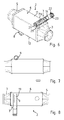
- FIGS. 1 to 5 Based on FIGS. 1 to 5 a first embodiment of an exhaust gas heat exchanger 1 is described.
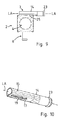
- the FIGS. 6 to 10 show a second embodiment of an exhaust heat exchanger.
- FIG. 11 shows a modification of the exhaust gas heat exchanger 2.
- the exhaust gas heat exchanger 1, 2 are used in particular as exhaust gas recirculation cooler in a motor vehicle. Hot exhaust gas flows in via an inflow diffuser 3 and is guided in the interior of the exhaust heat exchangers 1, 2 by means of a heat exchanger unit 4, in particular a tube bundle or a plate pack, to an outflow diffuser 5, from which the cooled exhaust gas flows. In the area between the diffusers 3, 5, the heat exchanger unit 4 is surrounded by a housing 6. Through the housing 6, a liquid coolant is passed, which flows around the heat exchanger unit 4. The coolant is supplied to a coolant inlet port 7 and discharged to a coolant outlet port 8.
- coolant inlet connection 7 and the coolant outlet connection 8 lie on opposite sides 11, 12 of the housing 6.
- the coolant inlet connection 7 is arranged on the upper side 11 of the housing 6 viewed in the image plane and the coolant outlet connection 8 on the underside 12.
- a connection for coolant namely the coolant inlet connection 7, is formed by a pipe section 13 or 14.
- the pipe section 13 or 14 has at its outer periphery 15 a joining surface 16, 17 for fixing to the housing 6.
- the joining surface 16, 17 is formed by a flattening of the pipe wall 18 of the pipe section 13, 14 (see in particular Figures 5 and 10 ).
- the pipe section 13, 14 has a laterally outgoing transfer opening 19, which communicates with the passage opening 9 in the housing 6 and is in fluid communication in connection.
- the Transfer opening 19 is aligned transversely to the longitudinal axis LA of the pipe section 13, 14.
- the surface normal of the transfer opening 19 is marked FN.
- the joining surface 16, 17 has a connection contour adapted to the outer contour of the housing 6.
- the pipe section 13 or 14 is mounted both on the exhaust gas heat exchanger 1 and the exhaust heat exchanger 2 radially on the housing 6.
- the housing-side end 20 of the pipe section 13, 14 is closed by an end wall 21.
- connecting means 23 are provided in the form of a radially encircling sealing bead for coupling of upstream pipe components.
- the transfer opening 19 is formed by a slot.
- the oblong hole is punched into the tube wall 18 and extends in the longitudinal direction of the flattened joining surface 16, 17.
- the housing 6 of the exhaust gas heat exchanger 1 is designed around.
- the pipe section 13 has a curved or circular section shaped joining surface 16 adapted to the outer contour of the housing 6.
- the connection surface 24 on the housing 6 is designed congruent.
- the free end 22 of the pipe section 13 extends tangentially away from the housing 6 away.
- the housing 6 of the exhaust gas heat exchanger 2 is rectangular in cross-section.
- the pipe section 14 extends in a straight line transversely to the longitudinal direction of the housing 6.
- the joining surface 17 of the pipe section 14 is configured in a straight line.
- the housing 6 has a congruent to the joining surface 17 designed connecting surface 25.
- the pipe section 14 goes over an arc section 26 in a rectilinear free end portion 27 of the coolant inlet port 7 over.
- FIG. 12 Another embodiment of a pipe section 28 shows the FIG. 12 ,
- the tube wall 29 is removed in a housing-side end portion 30 on a portion.
- the longitudinal edges 31, 32 in the remote area form a joining surface 33.
- the transfer opening 34 is aligned transversely to the longitudinal axis LA of the pipe section 28.
- exhaust gas heat exchanger 2 has a rectangular in cross-section housing 6.
- the coolant inlet connection 7 is formed by a pipe section 14 which has a joining surface 17 at its outer periphery 15 for fixing to the housing 6.
- the joining surface 17 is formed by a flattening of the pipe wall 18 of the pipe section 14.
- the pipe section 14 has a laterally arranged transfer opening 19.
- the transfer opening 19 is aligned transversely to the longitudinal axis LA of the pipe section 14.
- the transfer opening 19 is a slot which communicates with two passage openings 9 in the housing 6 and is in fluid communication with this.
- the pipe section 14 tapers toward its housing-side end 20.
- the housing-side end 20 is closed by a flattening 36. It can be seen that the tube wall is compressed at the housing-side end 20 and flattened on each other.
- the exhaust gas heat exchanger 2 is formed, as in the FIGS. 16 to 18 shown.
- the pipe section 14 extends in a straight line transversely to the longitudinal direction of the housing 6.
- the pipe section 14 tapers towards the housing-side end 20.
- a joining surface 17 is formed by a flattening of the tube wall on the housing-side end portion 20 of the pipe section 14.
- the joining surface 17 is configured parabolic.
- the transfer opening 19 is formed by a slot. The transfer opening 19 extends in the longitudinal direction of the pipe section and is arranged laterally on or in the pipe wall of the pipe section.
- the transfer opening 19 or the surface normal of the transfer opening 19 is aligned transversely to the longitudinal axis LA of the pipe section 14, so that the passage of coolant takes place laterally out of the pipe section 14 and into the housing 6 of the exhaust gas heat exchanger 2.
- the transfer opening communicates with two passage openings 9 in the upper side wall of the housing 6. Through passage openings 9 are elongated holes.
- the coolant connection 7 of the exhaust gas heat exchanger 2 as based on the FIGS. 13 to 15 and 16 to 18 explained, has a tube piece 14 which is radially attached to the housing 6.
- the joining surface 17 is respectively adapted to the outer contour of the housing 6 by a connection contour.
- connecting means 23 are provided at the free end 22 of the pipe section 14 at the free end 22 of the pipe section 14 .
- the coolant inlet port 7 is configured in accordance with the invention.
- the coolant outlet connection 8 is attached with its housing-side end face 35 to the housing 6 and joined there.
- the coolant outlet connection 8 is in fluid communication with the passage opening 10 in the housing 6 in connection. It is understood that the coolant outlet connection 8 is configured according to the invention with a pipe section according to the embodiment as described on the basis of the coolant inlet connection 7.
Abstract
Description
- Die Erfindung betrifft einen Abgaswärmeübertrager zur Übertragung von Wärme zwischen dem Abgas einer Brennkraftmaschine eines Kraftfahrzeuges und einem Kühlmittel gemäß den Merkmalen im Oberbegriff von Anspruch 1.
- Abgaswärmeübertrager und deren Aufbau sowie Funktionsweise sind beispielsweise durch die
EP 2 436 897 A2 , dieDE 601 19 740 T2 oder dieDE 199 07 163 C2 bekannt. Solche Wärmeübertrager kommen insbesondere als Abgasrückführungskühler oder auch Ladeluftkühler in Kraftfahrzeugen zum Einsatz. - Jeder Abgaswärmeübertrager benötigt Kühlmittelanschlüsse zur Zu- und Abführung von Kühlmittel. In der Regel sind die Anschlüsse als axiale Rohrstutzen ausgeführt, die mit dem Gehäuse gefügt sind. Externe Kühlmittelübergabestellen werden meistens mit Rohren versehen. Bauraumbedingt und aus Kostengründen sind die Kühlmittelübergabestellen nahe am Kühler. Um die jeweilige Position am Gehäuse des Abgaswärmeübertragers erreichen zu können, sind teilweise kleine Biegeradien an Rohrleitungen oder Aushalsungen am Gehäuse bzw. Gehäusemantel sowie zusätzliche Stanz- oder Frästeile erforderlich. Dies ist sowohl herstellungs- als auch montagetechnisch verbesserungswürdig.
- Die
DE 10 2011 077 459 A1 offenbart eine Verbindungsanordnung zwischen einem Anschlussrohr und einem an einem Wärmeübertrager vorgesehenem Verbindungspartner, wobei der Verbindungspartner zumindest eine formkomplementär zum Anschlussrohr ausgebildete Durchtrittsöffnung und zumindest eine Aufnahmeöffnung aufweist, in die das Endstück des Anschlussrohres zumindest bereichsweise unter Ausbildung eines Presssitzes eingesteckt werden kann. Der Verbindungspartner weist einen Aufnahmebereich für Lotmaterial auf, wobei sich der Aufnahmebereich am axial äußeren Ende der Durchtrittsöffnung erstreckt. Das Lotmaterial ist in dem Aufnahmebereich angeordnet. - Der Erfindung liegt ausgehend vom Stand der Technik die Aufgabe zugrunde, einen Abgaswärmeübertrager aufzuzeigen mit einer funktional und bauraumtechnisch verbesserten Verbindung zwischen Gehäuse und einem Kühlmittelanschluss.
- Die Lösung dieser Aufgabe besteht nach der Erfindung in einem Abgaswärmeübertrager gemäß den Merkmalen von Anspruch 1.
- Vorteilhafte Ausgestaltungen und Weiterbildungen der Erfindung sind Gegenstand der abhängigen Ansprüche 2 bis 10.
- Erfindungsgemäß weist zumindest ein Anschluss, insbesondere der Kühlmittelzulaufanschluss, ein Rohrstück auf mit einer an seinem Außenumfang ausgebildeten Fügefläche zur Festlegung des Rohrstückes am Gehäuse des Abgaswärmeübertragers und einer seitlich am Rohrstück angeordneten Überleitungsöffnung, welche mit einer Durchlassöffnung im Gehäuse kommuniziert.
- Insbesondere ist die Übergangsleitungsöffnung bzw. die Flächennormale der Überleitungsöffnung quer zur Längsachse des Rohrstücks ausgerichtet.
- Quer zur Längsachse bedeutet, die Überleitungsöffnung bzw. die sich durch den Flächenmittelpunkt der Überleitungsöffnung erstreckende Flächennormale in einem Winkel zur Längsachse ausgerichtet. Die Ausrichtung der Überleitungsöffnung erfolgt schräg zur Längsachse bzw. steht zur Längsachse in einem Winkel größer 0° und kleiner 180°. Insbesondere ist die Ausrichtung in einem Winkel von 45° bis 135°, vorzugsweise in einem Winkel von 90° +/- 30° ausgerichtet. In praktischer Ausgestaltung ist insbesondere eine Ausrichtung der Überleitungsöffnung rechtwinklig quer zur Längsachse vorgesehen. Die Überleitungsöffnung ist seitlich in bzw. an der Rohrwand des Rohrstücks vorgesehen.
- Die Erfindung schafft einen Abgaswärmeübertrager mit einem bauraumtechnisch vorteilhaften, platzsparenden und kostengünstigen Kühlmittelanschluss. Der Kühlmittelanschluss ist durch ein Rohrstück gebildet, welches radial am Gehäuse des Abgaswärmeübertragers angebracht ist und an der vorgesehenen Überleitungsstelle des Kühlmittels mit einer Überleitungsöffnung versehen ist. Das Rohrstück kann an der Überleitungsstelle vorzugsweise geplättet sein. An das Rohrstück können an dessen freiem Ende Rohrleitungskomponenten angeschlossen werden. Hierzu sind am freien Ende des Rohrstückes entsprechende Koppelelemente vorgesehen. Bei den Koppelelementen kann es sich beispielsweise um einen Dichtwulst handeln, insbesondere um eine angestauchte, radial umlaufende Dichtwulst am freien Ende des Rohrstückes. Das andere gehäuseseitige Ende des Rohrstückes ist stirnseitig verschlossen. Dies kann durch eine Stirnwand, ebenso wie durch eine Endkappe oder einen Stopfen bzw. ein Endstück geschehen.
- Eine vorteilhafte Ausgestaltung sieht vor, dass das Rohrstück sich zu seinem gehäuseseitigen Ende hin verjüngt. Vorteilhaft ist das Rohrstück an seinem gehäuseseitigen Ende durch eine Abplattung verschlossen. Die Rohrwand des Rohrstücks ist hierbei gestaucht und zusammengedrückt, so dass die Rohrwand bzw. Rohrwandabschnitte flach aneinander liegen. Insbesondere sind die Rohrwandabschnitte im Bereich der Abplattung fluiddicht miteinander gefügt.
- Insgesamt wird die Erreichbarkeit der Überleitungsöffnung bzw. Durchlassöffnung im Gehäuse des Abgaswärmeübertragers erleichtert und verbessert. Der erfindungsgemäße Kühlmittelanschluss ermöglicht auch das Erreichen von in der Einbaulage des Abgaswärmeübertragers ungünstig gelegenen Anschlussstellen bzw. Durchlassöffnungen im Gehäuse.
- Besonders vorteilhaft ist die Fügefläche durch eine Abflachung an der Rohrwand des Rohrstückes gebildet.
- Eine weitere vorteilhafte Ausgestaltung sieht vor, dass die Überleitungsöffnung durch ein in die Rohrwand des Rohrstückes gestanztes Loch gebildet ist. Die Überleitungsöffnung kann auch durch ein gefrästes oder ein gelasertes Loch in der Rohrwand des Rohrstücks hergestellt sein. Eine besonders effektive Überleitung des Kühlmittels erfolgt, wenn die Überleitungsöffnung als Langloch ausgebildet ist. Weiterhin können auch mehrere Überleitungsöffnungen vorgesehen sein. So ist es möglich, dass zwei oder mehr Löcher die Überleitungsöffnung bilden. Hierbei sind die Löcher insbesondere in Reihe in Längsrichtung des Rohrstücks angeordnet.
- Die Durchlassöffnung im Gehäuse ist strömungstechnisch für eine vorteilhafte Überleitung des Kühlmittels in bzw. aus den Abgaswärmeübertrager konfiguriert. Auch die Durchlassöffnung im Gehäuse bzw. dem Gehäusemantel kann als Rund- oder Langloch ausgebildet sein. Ein Aspekt sieht vor, dass ein oder mehrere Löcher in Reihe in Längsrichtung des Rohrstücks angeordnet sind.
- Ein weiterer Aspekt der Erfindung sieht vor, dass die Fügefläche eine an die Außenkontur des Gehäuses angepasste Anschlusskontur besitzt. Insbesondere weist die Fügefläche eine zur Anbindungsfläche am Gehäuse kongruente Ausgestaltung auf. Das Rohrstück des Kühlmittelanschlusses erstreckt sich radial am Gehäuse. An das freie Ende des Rohrstückes kann eine Kühlmittelleitung angeschlossen werden.
- Weiterhin ist vorteilhaft, dass das Gehäuse eine Anbindungsfläche für das Rohrstück bzw. einen Teil des Rohrstückes aufweist. Die Anbindungsfläche ist insbesondere kongruent zum Außenumfang des Rohrstückes im Bereich des Kühlmittelüberganges gestaltet. So kann der Aufnahmeabschnitt halbrund ausgestaltet sein, um das Rohrstück aufnehmen zu können.
- Bei der Ausgestaltung des Rohrstückes mit einer abgeflachten bzw. geplätteten Fügefläche ist die Anbindungsfläche im Gehäuse entsprechend eben gestaltet. Diese Ausgestaltung ist sowohl fertigungs- als auch montagetechnisch vorteilhaft.
- Insbesondere sind das Rohrstück und das Gehäuse miteinander stoffschlüssig gefügt, vorzugsweise verlötet.
- Der Abgaswärmeübertrager und dessen Komponenten bestehen aus Metall, insbesondere Stahlwerkstoffen, bevorzugt Edelstahl. Der Abgaswärmeübertrager oder Bauteilkomponenten von ihm können auch aus Leichtmetall, insbesondere Aluminium bestehen.
- Zur Herstellung des Kühlmittelanschlusses wird das Rohrstück bereichsweise geplättet und mit einem Dorn auf die Endgeometrie aufkalibriert. Anschließend wird die Überleitungsöffnung in die Rohrwand im abgeplätteten Bereich gestanzt, gefräst oder gelasert. Grundsätzlich können auch mehrere in Längsrichtung in Reihe angeordnete Überleitungsöffnungen im Rohrstück vorgesehen sein. Diese Ausgestaltung kann vorteilhafte Auswirkungen für die Verteilung des Kühlmittels innerhalb der Wärmeübertragereinheit im Gehäuse des Abgaswärmeübertragers haben.
- Eine andere Variante eines Rohrschiebers sieht vor, dass ein Teil bzw. Teilstück der Rohrwand des Rohrstückes entfernt ist, um so die Fügefläche und die radial ausgerichtete Überleitungsöffnung zu schaffen.
- Die Erfindung ist nachfolgend anhand von in den Zeichnungen dargestellten Ausführungsbeispielen näher beschrieben. Es zeigen:
- Figur 1
- eine erste Ausführungsform eines erfindungsgemäßen Abgaswärmeübertragers in einer perspektivischen Darstellung;
- Figur 2
- den Abgaswärmeübertrager gemäß der
Figur 1 in einer Seitenansicht; - Figur 3
- die Darstellung gemäß der
Figur 2 in einer Draufsicht; - Figur 4
- den Abgaswärmeübertrager in einer Stirnansicht;
- Figur 5
- den Kühlmittelanschluss des Abgaswärmeübertragers in einer perspektivischen Ansicht;
- Figur 6
- eine zweite Ausführungsform eines erfindungsgemäßen Abgaswärmeübertragers in einer perspektivischen Ansicht;
- Figur 7
- den Abgaswärmeübertrager gemäß der
Figur 6 in einer Seitenansicht; - Figur 8
- den Abgaswärmeübertrager in einer Draufsicht;
- Figur 9
- den Abgaswärmeübertrager in einer Stirnansicht;
- Figur 10
- den Kühlmittelanschluss des Abgaswärmeübertragers gemäß der
Figur 6 in einer perspektivischen Ansicht; - Figur 11
- einen Ausschnitt aus einem Abgaswärmeübertrager entsprechend der
Figur 6 im Bereich des Kühlmittelanschlusses in einer Perspektive; - Figur 12
- eine andere Ausführungsform eines Kühlmittelanschlusses in einer Perspektive;
- Figur 13
- eine weitere Ausführungsform eines erfindungsgemäßen Abgaswärmeübertragers in einer perspektivischen Ansicht;
- Figur 14
- den Kühlmittelanschluss des Abgaswärmeübertragers gemäß der
Figur 13 in einer perspektivischen Ansicht; - Figur 15
- eine Abwandlung des Abgaswärmeübertragers gemäß der
Figur 13 in einer Perspektive; - Figur 16
- eine weitere Ausführungsform eines erfindungsgemäßen Abgaswärmeübertragers in einer perspektivischen Darstellung;
- Figur 17
- den Kühlmittelanschluss des Abgaswärmeübertragers gemäß der
Figur 16 in einer perspektivischen Ansicht und - Figur 18
- den Abgaswärmeübertrager gemäß der Darstellung von
Figur 16 in einer Perspektive mit einer Ansicht auf den Kühlmittelübergang. - Einander entsprechende Bauteile und Bauteilkomponenten sind in allen Figuren mit den gleichen Bezugszeichen versehen.
- Anhand der
Figuren 1 bis 5 ist eine erste Ausführungsform eines Abgaswärmeübertragers 1 beschrieben. DieFiguren 6 bis 10 zeigen eine zweite Ausführungsform eines Abgaswärmeübertragers 2.Figur 11 zeigt eine Modifikation des Abgaswärmeübertragers 2. - Die Abgaswärmeübertrager 1, 2 werden insbesondere als Abgasrückführungskühler in einem Kraftfahrzeug eingesetzt. Heißes Abgas strömt über einen Einströmdiffusor 3 ein und wird im Inneren der Abgaswärmeübertrager 1, 2 mittels einer Wärmetauschereinheit 4, insbesondere einem Rohrbündel oder einem Plattenpaket zu einem Ausströmdiffusor 5 geführt, aus dem das gekühlte Abgas abströmt. Im Bereich zwischen den Diffusoren 3, 5 ist die Wärmetauschereinheit 4 von einem Gehäuse 6 umgeben. Durch das Gehäuse 6 wird ein flüssiges Kühlmittel geführt, welches die Wärmetauschereinheit 4 umströmt. Das Kühlmittel wird an einem Kühlmittelzulaufanschluss 7 zugeführt und an einem Kühlmittelablaufanschluss 8 abgeführt. Zur Einleitung von Kühlmittel über den Kühlmittezulaufanschluss 7 sowie zur Ableitung von Kühlmittel über den Kühlmittelablaufanschluss 8 sind im Gehäuse 6 Durchlassöffnungen 9, 10 vorgesehen. Der Kühlmittelzulaufanschluss 7 und der Kühlmittelablaufanschluss 8 liegen auf einander gegenüberliegenden Seiten 11, 12 des Gehäuses 6. Vorliegend ist der Kühlmittelzulaufanschluss 7 auf der in Bildebene gesehenen Oberseite 11 des Gehäuses 6 und der Kühlmittelablaufanschluss 8 auf der Unterseite 12 angeordnet.
- Ein Anschluss für Kühlmittel, nämlich der Kühlmittelzulaufanschluss 7, ist durch ein Rohrstück 13 bzw. 14 gebildet. Das Rohrstück 13 bzw. 14 weist an seinem Außenumfang 15 eine Fügefläche 16, 17 zur Festlegung am Gehäuse 6 auf. Die Fügefläche 16, 17 ist durch eine Abflachung der Rohrwand 18 des Rohrstückes 13, 14 gebildet (siehe hierzu insbesondere
Figuren 5 und10 ). - Im Bereich der abgeflachten Fügefläche 16, 17 weist das Rohrstück 13, 14 eine seitlich abgehende Überleitungsöffnung 19 auf, welche mit der Durchlassöffnung 9 im Gehäuse 6 kommuniziert und fluidleitend in Verbindung steht. Die Überleitungsöffnung 19 ist quer zur Längsachse LA des Rohrstückes 13, 14 ausgerichtet. Die Flächennormale der Überleitungsöffnung 19 ist mit FN gekennzeichnet.
- Die Fügefläche 16, 17 besitzt eine an die Außenkontur des Gehäuses 6 angepasste Anschlusskontur.
- Das Rohrstück 13 bzw. 14 ist sowohl beim Abgaswärmeübertrager 1 als auch beim Abgaswärmeübertrager 2 radial am Gehäuse 6 angebracht. Das gehäuseseitige Ende 20 des Rohrstückes 13, 14 ist durch eine Stirnwand 21 verschlossen. Am freien Ende 22 des Rohrstückes 13, 14 sind Verbindungsmittel 23 in Form einer radial umlaufenden Dichtwulst zur Ankopplung von vorgeschalteten Rohrleitungskomponenten vorgesehen.
- Wie wiederum insbesondere die
Figuren 5 und10 erkennen lassen, ist die Überleitungsöffnung 19 durch ein Langloch gebildet. Das Langloch ist in die Rohrwand 18 gestanzt und erstreckt sich in Längsrichtung der abgeplatteten Fügefläche 16, 17. - Das Gehäuse 6 des Abgaswärmeübertragers 1 ist rund gestaltet. In kongruenter Ausgestaltung hierzu weist das Rohrstück 13 eine an die Außenkontur des Gehäuses 6 angepasste gekrümmte bzw. kreisabschnittsförmig gestaltete Fügefläche 16 auf. Die Anbindungsfläche 24 am Gehäuse 6 ist kongruent gestaltet. Das freie Ende 22 des Rohrstückes 13 erstreckt sich tangential abgehend vom Gehäuse 6 weg.
- Das Gehäuse 6 des Abgaswärmeübertragers 2 ist im Querschnitt rechteckig gestaltet. Das Rohrstück 14 verläuft geradlinig quer zur Längsrichtung des Gehäuses 6. Die Fügefläche 17 des Rohrstückes 14 ist eben geradlinig konfiguriert. Das Gehäuse 6 weist eine zur Fügefläche 17 kongruent ausgestaltete Anbindungsfläche 25 auf.
- Bei der Ausgestaltung des Abgaswärmeübertragers 2, wie in der
Figur 11 dargestellt, geht das Rohrstück 14 über einen Bogenabschnitt 26 in einen geradlinig verlaufenden freien Endabschnitt 27 des Kühlmittelzulaufanschlusses 7 über. - Eine andere Ausgestaltung eines Rohrstückes 28 zeigt die
Figur 12 . Bei dieser Ausführungsform ist die Rohrwand 29 in einem gehäuseseitigen Endabschnitt 30 auf einem Teilstück entfernt. Die Längskanten 31, 32 im entfernten Bereich bilden eine Fügefläche 33. Die Überleitungsöffnung 34 ist quer zur Längsachse LA des Rohrstückes 28 ausgerichtet. - Auch der in den
Figuren 13 bis 15 dargestellte Abgaswärmeübertrager 2 weist ein in Querschnitt rechtseckig ausgeführtes Gehäuse 6 auf. Der Kühlmittelzulaufanschluss 7 ist durch ein Rohrstück 14 gebildet, welches an seinem Außenumfang 15 eine Fügefläche 17 zur Festlegung am Gehäuse 6 aufweist. Die Fügefläche 17 ist durch eine Abflachung der Rohrwand 18 des Rohrstücks 14 gebildet. Im Bereich der Fügefläche 17 weist das Rohrstück 14 eine seitlich angeordnete Überleitungsöffnung 19 auf. Die Überleitungsöffnung 19 ist quer zur Längsachse LA des Rohrstücks 14 ausgerichtet. Die Überleitungsöffnung 19 ist ein Langloch, welches mit zwei Durchlassöffnungen 9 im Gehäuse 6 kommuniziert und mit diesem fluidleitend in Verbindung steht. Das Rohrstück 14 verjüngt sich zu seinem gehäuseseitigen Ende 20 hin. Hierbei ist das gehäuseseitige Ende 20 durch eine Abplattung 36 verschlossen. Man erkennt, dass die Rohrwand am gehäuseseitigen Ende 20 gestaucht und aufeinander geplättet ist. - Konfigurativ gleichartig ist der Abgaswärmeübertrager 2 ausgebildet, wie in den
Figuren 16 bis 18 dargestellt. Das Rohrstück 14 verläuft gradlinig quer zur Längsrichtung des Gehäuses 6. Das Rohrstück 14 verjüngt sich zum gehäuseseitigen Ende 20 hin. Hierbei ist eine Fügefläche 17 durch eine Abflachung der Rohrwand am gehäuseseitigen Endabschnitt 20 des Rohrstücks 14 ausgebildet. Die Fügefläche 17 ist parabelförmig konfiguriert. Die Überleitungsöffnung 19 ist durch ein Langloch gebildet. Die Überleitungsöffnung 19 erstreckt sich in Längsrichtung des Rohrstücks und ist seitlich an bzw. in der Rohrwand des Rohrstücks angeordnet. Hierbei ist die Überleitungsöffnung 19 bzw. die Flächennormale der Überleitungsöffnung 19 quer zur Längsachse LA des Rohrstücks 14 ausgerichtet, so dass der Durchschuss von Kühlmittel seitlich aus dem Rohrstück 14 und in das Gehäuse 6 des Abgaswärmeübertragers 2 erfolgt. Die Überleitungsöffnung kommuniziert mit zwei Durchlassöffnungen 9 in der oberen Seitenwand des Gehäuses 6. Durch Durchlassöffnungen 9 sind Langlöcher. - Der Kühlmittelanschluss 7 der Abgaswärmeübertrager 2, wie anhand der
Figuren 13 bis 15 bzw. 16 bis 18 erläutert, weist ein Rohrstück 14 auf, welches radial am Gehäuse 6 angebracht ist. Die Fügefläche 17 ist jeweils an die Außenkontur des Gehäuses 6 durch eine Anschlusskontur angepasst. Am freien Ende 22 des Rohrstücks 14 sind Verbindungsmittel 23 vorgesehen. - In den dargestellten Ausführungsbeispielen ist der Kühlmittelzulaufanschluss 7 in erfindungsgemäßer Weise ausgestaltet. Der Kühlmittelablaufanschluss 8 ist mit seiner gehäuseseitigen Stirnseite 35 an das Gehäuse 6 angesetzt und dort gefügt. Der Kühlmittelablaufanschluss 8 steht fluidleitend mit der Durchlassöffnung 10 im Gehäuse 6 in Verbindung. Es versteht sich, dass auch der Kühlmittelablaufanschluss 8 erfindungsgemäß ausgestaltet ist mit einem Rohrstück entsprechend der Ausgestaltung wie anhand dem Kühlmittelzulaufanschluss 7 beschrieben.
-
- 1 -
- Abgaswärmeübertrager
- 2 -
- Abgaswärmeübertrager
- 3 -
- Einströmdiffusor
- 4 -
- Wärmetauschereinheit
- 5 -
- Ausströmdiffusor
- 6 -
- Gehäuse
- 7 -
- Kühlmittelzulaufanschluss
- 8 -
- Kühlmittelablaufanschluss
- 9 -
- Durchlassöffnung
- 10 -
- Durchlassöffnung
- 11 -
- Oberseite von 6
- 12 -
- Unterseite von 6
- 13 -
- Rohrstück
- 14 -
- Rohrstück
- 15 -
- Außenumfang
- 16 -
- Fügefläche
- 17 -
- Fügefläche
- 18 -
- Rohrwand
- 19 -
- Überleitungsöffnung
- 20 -
- gehäuseseitiges Ende von 13, 14
- 21 -
- Stirnwand
- 22 -
- freies Ende von 13, 14
- 23 -
- Verbindungsmittel
- 24 -
- Anbindungsfläche
- 25 -
- Anbindungsfläche
- 26 -
- Bogenabschnitt
- 27 -
- Endabschnitt
- 28 -
- Rohrstück
- 29 -
- Rohrwand
- 30 -
- Endabschnitt
- 31 -
- Längskante
- 32 -
- Längskante
- 33 -
- Fügefläche
- 34 -
- Überleitungsöffnung
- 35 -
- gehäuseseitige Stirnseite von 8
- 36 -
- Abplattung
- LA -
- Längsachse
- FN -
- Flächennormale
Claims (10)
- Abgaswärmeübertrager (1, 2) zur Übertragung von Wärme zwischen dem Abgas einer Brennkraftmaschine eines Kraftfahrzeuges und einem Kühlmittel mit einem Gehäuse (6), welches Anschlüsse (7, 8) zur Zu- und Abführung von Kühlmittel aufweist, dadurch gekennzeichnet, dass zumindest ein Anschluss (7, 8) ein Rohrstück (13, 14; 28) aufweist mit einer an seinem Außenumfang (15) ausgebildeten Fügefläche (16, 17) zur Festlegung am Gehäuse (6) und einer quer zur Längsachse (LA) des Rohrstückes (13, 14; 28) ausgerichteten Überleitungsöffnung (19; 34), welche mit einer Durchlassöffnung (9, 10) im Gehäuse (6) kommuniziert.
- Abgaswärmeübertrager nach Anspruch 1, dadurch gekennzeichnet, dass die Überleitungsöffnung (19; 34) quer zur Längsachse (LA) des Rohrstücks (13, 14; 28) ausgerichtet ist.
- Abgaswärmeübertrager nach Anspruch 1 oder 2, dadurch gekennzeichnet, dass die Fügefläche (16, 17) durch eine Abflachung der Rohrwand (18) des Rohrstückes (13, 14) gebildet ist.
- Abgaswärmeübertrager nach einem der Ansprüche 1 bis 3, dadurch gekennzeichnet, dass die Fügefläche (16, 17) eine an die Außenkontur des Gehäuses (6) angepasste Anschlusskontur besitzt.
- Abgaswärmeübertrager nach wenigstens einem der Ansprüche 1 bis 4, dadurch gekennzeichnet, dass das Rohrstück (13, 14) radial am Gehäuse (6) angebracht ist.
- Abgaswärmeübertrager nach wenigstens einem der Ansprüche 1 bis 5, dadurch gekennzeichnet, dass die Überleitungsöffnung (19) durch ein oder mehrere Löcher in den Rohrwänden (18), insbesondere durch ein Langloch, gebildet ist.
- Abgaswärmeübertrager nach wenigstens einem der Ansprüche 1 bis 6, dadurch gekennzeichnet, dass das Gehäuse (6) eine zur Fügefläche (16, 17) des Rohrstückes (13, 14) kongruent ausgestaltete Anbindungsfläche (24, 25) aufweist.
- Abgaswärmeübertrager nach wenigstens einem der Ansprüche 1 bis 7, dadurch gekennzeichnet, dass sich das Rohrstück (14) zu seinem gehäuseseitigen Ende (20) hin verjüngt.
- Abgaswärmeübertrager nach wenigstens einem der Ansprüche 1 bis 8, dadurch gekennzeichnet, dass das gehäuseseitige Ende (20) des Rohrstücks (13, 14) stirnseitig verschlossen ist.
- Abgaswärmeübertrager nach wenigstens einem der Ansprüche 1 bis 9, dadurch gekennzeichnet, dass das Rohrstück (14) an seinem gehäuseseitigen Ende (20) durch eine Abplattung (36) verschlossen ist.
Applications Claiming Priority (1)
| Application Number | Priority Date | Filing Date | Title |
|---|---|---|---|
| DE102014119227.3A DE102014119227A1 (de) | 2014-12-19 | 2014-12-19 | Abgaswärmeübertrager |
Publications (2)
| Publication Number | Publication Date |
|---|---|
| EP3034979A1 true EP3034979A1 (de) | 2016-06-22 |
| EP3034979B1 EP3034979B1 (de) | 2019-02-06 |
Family
ID=54849107
Family Applications (1)
| Application Number | Title | Priority Date | Filing Date |
|---|---|---|---|
| EP15198759.1A Active EP3034979B1 (de) | 2014-12-19 | 2015-12-09 | Abgaswärmeübertrager |
Country Status (4)
| Country | Link |
|---|---|
| US (1) | US9995250B2 (de) |
| EP (1) | EP3034979B1 (de) |
| CN (1) | CN105716447B (de) |
| DE (1) | DE102014119227A1 (de) |
Cited By (3)
| Publication number | Priority date | Publication date | Assignee | Title |
|---|---|---|---|---|
| FR3063523A1 (fr) * | 2017-03-06 | 2018-09-07 | Manitou Bf | Groupe motopropulseur a moteur a combustion interne suralimente |
| FR3081516A1 (fr) * | 2018-05-25 | 2019-11-29 | Renault S.A.S. | Dispositif de refroidissement des gaz recircules egr equipe d'un conduit peripherique de distribution de liquide de refroidissement |
| EP3786567A1 (de) * | 2019-08-26 | 2021-03-03 | Valeo Termico S.A. | Agr-kühler |
Families Citing this family (2)
| Publication number | Priority date | Publication date | Assignee | Title |
|---|---|---|---|---|
| CN106482367A (zh) * | 2016-12-01 | 2017-03-08 | 浙江鸿乐光热科技有限公司 | 一种太阳能热水器水管座导流接头 |
| CN114152112B (zh) * | 2020-06-02 | 2023-09-22 | 合肥通用机械研究院有限公司 | 一种用于高温气体冷却器的分布盘 |
Citations (10)
| Publication number | Priority date | Publication date | Assignee | Title |
|---|---|---|---|---|
| DE19907163C2 (de) | 1998-04-24 | 2003-08-14 | Behr Gmbh & Co | Wärmetauscher, insbesondere Abgaswärmetauscher |
| JP2003314928A (ja) * | 2002-04-19 | 2003-11-06 | Denso Corp | 受液器一体型凝縮器 |
| DE102005028806A1 (de) * | 2005-06-22 | 2007-01-11 | GM Global Technology Operations, Inc., Detroit | Ansaugkanal für einen Verbrennungsmotor |
| DE60119740T2 (de) | 2000-07-28 | 2007-02-22 | Serck Heat Transfer Ltd. | Abgaskühler mit umgehungsleitung und abgasrückführventil |
| DE102006045535A1 (de) * | 2005-10-19 | 2007-05-03 | Behr Gmbh & Co. Kg | Wärmeübertrager |
| KR100748756B1 (ko) * | 2006-05-11 | 2007-08-13 | 현대자동차주식회사 | 차량용 egr 장치의 egr 쿨러 |
| JP2009114923A (ja) * | 2007-11-05 | 2009-05-28 | Tokyo Radiator Mfg Co Ltd | Egrクーラ |
| DE102011077459A1 (de) | 2010-06-15 | 2011-12-15 | Behr Gmbh & Co. Kg | Verbindungsanordnung |
| EP2436897A2 (de) | 2010-10-04 | 2012-04-04 | MAHLE International GmbH | Kühler |
| WO2013022072A1 (ja) * | 2011-08-10 | 2013-02-14 | 臼井国際産業株式会社 | 多管式熱交換器 |
Family Cites Families (12)
| Publication number | Priority date | Publication date | Assignee | Title |
|---|---|---|---|---|
| US2387476A (en) * | 1943-09-29 | 1945-10-23 | Charles B Taylor | Muffler |
| US3813039A (en) * | 1973-03-26 | 1974-05-28 | G Wells | Heat exchanger |
| NO145589C (no) * | 1977-06-30 | 1982-04-21 | Rosenblad Corp | Fremgangsmaate for kondensasjon av damp i en varmeveksler samt en varmeveksler til bruk ved fremgangsmaaten |
| US5123480A (en) * | 1991-08-05 | 1992-06-23 | Riley Stoker Corporation | Integrated heat exchanger |
| JP4098406B2 (ja) * | 1998-06-26 | 2008-06-11 | カルソニックカンセイ株式会社 | 熱交換器用タンクへのフィラーネック取付構造 |
| EP1777480B1 (de) * | 2005-10-19 | 2018-11-28 | MAHLE Behr GmbH & Co. KG | Wärmeübertrager |
| US8978740B2 (en) * | 2006-06-22 | 2015-03-17 | Modine Manufacturing Company | Heat exchanger |
| US7857040B1 (en) * | 2007-09-05 | 2010-12-28 | Power Flow Systems, Inc. | Heat exchanger for aircraft exhaust |
| US8235592B2 (en) * | 2009-10-07 | 2012-08-07 | Wika Alexander Wiegand Se & Co. Kg | Gauge on a pipe section |
| CN202562353U (zh) * | 2012-05-28 | 2012-11-28 | 卡特彼勒公司 | 热交换器以及具有该热交换器的机器 |
| DE102014213718A1 (de) * | 2014-07-15 | 2016-01-21 | Mahle International Gmbh | Wärmeübertrager |
| DE102014214768A1 (de) * | 2014-07-28 | 2016-01-28 | Eberspächer Climate Control Systems GmbH & Co. KG | Wärmetauscheranordnung, insbesondere für ein Fahrzeugheizgerät |
-
2014
- 2014-12-19 DE DE102014119227.3A patent/DE102014119227A1/de not_active Ceased
-
2015
- 2015-12-09 EP EP15198759.1A patent/EP3034979B1/de active Active
- 2015-12-18 CN CN201510956468.2A patent/CN105716447B/zh active Active
- 2015-12-18 US US14/973,985 patent/US9995250B2/en active Active
Patent Citations (10)
| Publication number | Priority date | Publication date | Assignee | Title |
|---|---|---|---|---|
| DE19907163C2 (de) | 1998-04-24 | 2003-08-14 | Behr Gmbh & Co | Wärmetauscher, insbesondere Abgaswärmetauscher |
| DE60119740T2 (de) | 2000-07-28 | 2007-02-22 | Serck Heat Transfer Ltd. | Abgaskühler mit umgehungsleitung und abgasrückführventil |
| JP2003314928A (ja) * | 2002-04-19 | 2003-11-06 | Denso Corp | 受液器一体型凝縮器 |
| DE102005028806A1 (de) * | 2005-06-22 | 2007-01-11 | GM Global Technology Operations, Inc., Detroit | Ansaugkanal für einen Verbrennungsmotor |
| DE102006045535A1 (de) * | 2005-10-19 | 2007-05-03 | Behr Gmbh & Co. Kg | Wärmeübertrager |
| KR100748756B1 (ko) * | 2006-05-11 | 2007-08-13 | 현대자동차주식회사 | 차량용 egr 장치의 egr 쿨러 |
| JP2009114923A (ja) * | 2007-11-05 | 2009-05-28 | Tokyo Radiator Mfg Co Ltd | Egrクーラ |
| DE102011077459A1 (de) | 2010-06-15 | 2011-12-15 | Behr Gmbh & Co. Kg | Verbindungsanordnung |
| EP2436897A2 (de) | 2010-10-04 | 2012-04-04 | MAHLE International GmbH | Kühler |
| WO2013022072A1 (ja) * | 2011-08-10 | 2013-02-14 | 臼井国際産業株式会社 | 多管式熱交換器 |
Cited By (3)
| Publication number | Priority date | Publication date | Assignee | Title |
|---|---|---|---|---|
| FR3063523A1 (fr) * | 2017-03-06 | 2018-09-07 | Manitou Bf | Groupe motopropulseur a moteur a combustion interne suralimente |
| FR3081516A1 (fr) * | 2018-05-25 | 2019-11-29 | Renault S.A.S. | Dispositif de refroidissement des gaz recircules egr equipe d'un conduit peripherique de distribution de liquide de refroidissement |
| EP3786567A1 (de) * | 2019-08-26 | 2021-03-03 | Valeo Termico S.A. | Agr-kühler |
Also Published As
| Publication number | Publication date |
|---|---|
| CN105716447A (zh) | 2016-06-29 |
| US9995250B2 (en) | 2018-06-12 |
| US20160177888A1 (en) | 2016-06-23 |
| CN105716447B (zh) | 2019-02-15 |
| EP3034979B1 (de) | 2019-02-06 |
| DE102014119227A1 (de) | 2016-06-23 |
Similar Documents
| Publication | Publication Date | Title |
|---|---|---|
| EP3034979B1 (de) | Abgaswärmeübertrager | |
| DE112012005326T5 (de) | Abgaswärmetauschervorrichtung | |
| DE112017005880B4 (de) | Gestapelter Wärmetauscher | |
| EP3105525A1 (de) | Ladeluftkühler für eine frischluftanlage einer brennkraftmaschine | |
| EP1376043B1 (de) | Wärmetauscher mit einem Diffusor | |
| DE102015111393A1 (de) | Vorrichtung zur Wärmeübertragung | |
| DE102015111398A1 (de) | Vorrichtung zur Wärmeübertragung | |
| EP3097379B1 (de) | Wärmeübertrager | |
| DE102014200864A1 (de) | Wärmeübertrager | |
| EP1926961A1 (de) | Wärmeübertrager, insbesondere gaskühler | |
| EP3303969B1 (de) | Kombination eines wärmetauschers und mindestens zwei alternativ an den wärmetauscher anschliessbarer anschlusselemente | |
| DE102009032851A1 (de) | Wärmetauscher | |
| DE102010025030B4 (de) | Wärmetauscher für einen Verbrennungsmotor | |
| EP3591268B1 (de) | Fluidleitungsverbinder mit fixiertem einsatzteil zur drosslung | |
| EP2287552B1 (de) | Wärmeübertrager | |
| WO2017153210A1 (de) | Filteranschlussvorrichtung einer filtervorrichtung zum anschluss eines austauschbaren filters und filtervorrichtung | |
| DE102009020416A1 (de) | Flanschverbindung | |
| DE102015219653A1 (de) | Diffusor für einen Wärmeübertrager | |
| DE102022211533A1 (de) | Kühler und Verfahren zur Herstellung eines Kühlers | |
| DE60210223T2 (de) | Anschlussstutzen für Wärmetauscher | |
| DE102009042258B4 (de) | Wärmeübertragungsvorrichtung | |
| WO2021028103A1 (de) | Wärmetauscheranordnung, verfahren zur herstellung einer wärmetauscheranordnung und brennkraftmaschine mit wärmetauscheranordnung | |
| DE102022211531A1 (de) | Kühler und Verfahren zur Herstellung eines Kühlers | |
| DE202023107642U1 (de) | Abgasrohrbrücke | |
| DE102020004254A1 (de) | Anordnung sowie Verfahren zum Bereitsellen einer Anordnung einer Fluidanschlusseinrichtung an einem eine Kofferraummulde bereitstellenden Kofferraumbauteil eines Kraftwagens |
Legal Events
| Date | Code | Title | Description |
|---|---|---|---|
| PUAI | Public reference made under article 153(3) epc to a published international application that has entered the european phase |
Free format text: ORIGINAL CODE: 0009012 |
|
| 17P | Request for examination filed |
Effective date: 20160512 |
|
| AK | Designated contracting states |
Kind code of ref document: A1 Designated state(s): AL AT BE BG CH CY CZ DE DK EE ES FI FR GB GR HR HU IE IS IT LI LT LU LV MC MK MT NL NO PL PT RO RS SE SI SK SM TR |
|
| AX | Request for extension of the european patent |
Extension state: BA ME |
|
| GRAP | Despatch of communication of intention to grant a patent |
Free format text: ORIGINAL CODE: EPIDOSNIGR1 |
|
| STAA | Information on the status of an ep patent application or granted ep patent |
Free format text: STATUS: GRANT OF PATENT IS INTENDED |
|
| RIC1 | Information provided on ipc code assigned before grant |
Ipc: F28F 9/02 20060101AFI20180924BHEP Ipc: F02M 26/32 20160101ALI20180924BHEP Ipc: F02B 29/04 20060101ALI20180924BHEP Ipc: F02M 26/28 20160101ALI20180924BHEP Ipc: F28D 7/16 20060101ALI20180924BHEP Ipc: F28D 21/00 20060101ALI20180924BHEP |
|
| INTG | Intention to grant announced |
Effective date: 20181018 |
|
| GRAS | Grant fee paid |
Free format text: ORIGINAL CODE: EPIDOSNIGR3 |
|
| GRAA | (expected) grant |
Free format text: ORIGINAL CODE: 0009210 |
|
| STAA | Information on the status of an ep patent application or granted ep patent |
Free format text: STATUS: THE PATENT HAS BEEN GRANTED |
|
| AK | Designated contracting states |
Kind code of ref document: B1 Designated state(s): AL AT BE BG CH CY CZ DE DK EE ES FI FR GB GR HR HU IE IS IT LI LT LU LV MC MK MT NL NO PL PT RO RS SE SI SK SM TR |
|
| REG | Reference to a national code |
Ref country code: GB Ref legal event code: FG4D Free format text: NOT ENGLISH |
|
| REG | Reference to a national code |
Ref country code: CH Ref legal event code: EP Ref country code: AT Ref legal event code: REF Ref document number: 1095183 Country of ref document: AT Kind code of ref document: T Effective date: 20190215 |
|
| REG | Reference to a national code |
Ref country code: IE Ref legal event code: FG4D Free format text: LANGUAGE OF EP DOCUMENT: GERMAN |
|
| REG | Reference to a national code |
Ref country code: DE Ref legal event code: R096 Ref document number: 502015007877 Country of ref document: DE |
|
| REG | Reference to a national code |
Ref country code: NL Ref legal event code: MP Effective date: 20190206 |
|
| REG | Reference to a national code |
Ref country code: LT Ref legal event code: MG4D |
|
| PG25 | Lapsed in a contracting state [announced via postgrant information from national office to epo] |
Ref country code: NO Free format text: LAPSE BECAUSE OF FAILURE TO SUBMIT A TRANSLATION OF THE DESCRIPTION OR TO PAY THE FEE WITHIN THE PRESCRIBED TIME-LIMIT Effective date: 20190506 Ref country code: SE Free format text: LAPSE BECAUSE OF FAILURE TO SUBMIT A TRANSLATION OF THE DESCRIPTION OR TO PAY THE FEE WITHIN THE PRESCRIBED TIME-LIMIT Effective date: 20190206 Ref country code: FI Free format text: LAPSE BECAUSE OF FAILURE TO SUBMIT A TRANSLATION OF THE DESCRIPTION OR TO PAY THE FEE WITHIN THE PRESCRIBED TIME-LIMIT Effective date: 20190206 Ref country code: PT Free format text: LAPSE BECAUSE OF FAILURE TO SUBMIT A TRANSLATION OF THE DESCRIPTION OR TO PAY THE FEE WITHIN THE PRESCRIBED TIME-LIMIT Effective date: 20190606 Ref country code: NL Free format text: LAPSE BECAUSE OF FAILURE TO SUBMIT A TRANSLATION OF THE DESCRIPTION OR TO PAY THE FEE WITHIN THE PRESCRIBED TIME-LIMIT Effective date: 20190206 Ref country code: LT Free format text: LAPSE BECAUSE OF FAILURE TO SUBMIT A TRANSLATION OF THE DESCRIPTION OR TO PAY THE FEE WITHIN THE PRESCRIBED TIME-LIMIT Effective date: 20190206 |
|
| PG25 | Lapsed in a contracting state [announced via postgrant information from national office to epo] |
Ref country code: LV Free format text: LAPSE BECAUSE OF FAILURE TO SUBMIT A TRANSLATION OF THE DESCRIPTION OR TO PAY THE FEE WITHIN THE PRESCRIBED TIME-LIMIT Effective date: 20190206 Ref country code: HR Free format text: LAPSE BECAUSE OF FAILURE TO SUBMIT A TRANSLATION OF THE DESCRIPTION OR TO PAY THE FEE WITHIN THE PRESCRIBED TIME-LIMIT Effective date: 20190206 Ref country code: GR Free format text: LAPSE BECAUSE OF FAILURE TO SUBMIT A TRANSLATION OF THE DESCRIPTION OR TO PAY THE FEE WITHIN THE PRESCRIBED TIME-LIMIT Effective date: 20190507 Ref country code: IS Free format text: LAPSE BECAUSE OF FAILURE TO SUBMIT A TRANSLATION OF THE DESCRIPTION OR TO PAY THE FEE WITHIN THE PRESCRIBED TIME-LIMIT Effective date: 20190606 Ref country code: BG Free format text: LAPSE BECAUSE OF FAILURE TO SUBMIT A TRANSLATION OF THE DESCRIPTION OR TO PAY THE FEE WITHIN THE PRESCRIBED TIME-LIMIT Effective date: 20190506 Ref country code: RS Free format text: LAPSE BECAUSE OF FAILURE TO SUBMIT A TRANSLATION OF THE DESCRIPTION OR TO PAY THE FEE WITHIN THE PRESCRIBED TIME-LIMIT Effective date: 20190206 |
|
| PG25 | Lapsed in a contracting state [announced via postgrant information from national office to epo] |
Ref country code: DK Free format text: LAPSE BECAUSE OF FAILURE TO SUBMIT A TRANSLATION OF THE DESCRIPTION OR TO PAY THE FEE WITHIN THE PRESCRIBED TIME-LIMIT Effective date: 20190206 Ref country code: ES Free format text: LAPSE BECAUSE OF FAILURE TO SUBMIT A TRANSLATION OF THE DESCRIPTION OR TO PAY THE FEE WITHIN THE PRESCRIBED TIME-LIMIT Effective date: 20190206 Ref country code: CZ Free format text: LAPSE BECAUSE OF FAILURE TO SUBMIT A TRANSLATION OF THE DESCRIPTION OR TO PAY THE FEE WITHIN THE PRESCRIBED TIME-LIMIT Effective date: 20190206 Ref country code: EE Free format text: LAPSE BECAUSE OF FAILURE TO SUBMIT A TRANSLATION OF THE DESCRIPTION OR TO PAY THE FEE WITHIN THE PRESCRIBED TIME-LIMIT Effective date: 20190206 Ref country code: RO Free format text: LAPSE BECAUSE OF FAILURE TO SUBMIT A TRANSLATION OF THE DESCRIPTION OR TO PAY THE FEE WITHIN THE PRESCRIBED TIME-LIMIT Effective date: 20190206 Ref country code: SK Free format text: LAPSE BECAUSE OF FAILURE TO SUBMIT A TRANSLATION OF THE DESCRIPTION OR TO PAY THE FEE WITHIN THE PRESCRIBED TIME-LIMIT Effective date: 20190206 Ref country code: IT Free format text: LAPSE BECAUSE OF FAILURE TO SUBMIT A TRANSLATION OF THE DESCRIPTION OR TO PAY THE FEE WITHIN THE PRESCRIBED TIME-LIMIT Effective date: 20190206 Ref country code: AL Free format text: LAPSE BECAUSE OF FAILURE TO SUBMIT A TRANSLATION OF THE DESCRIPTION OR TO PAY THE FEE WITHIN THE PRESCRIBED TIME-LIMIT Effective date: 20190206 |
|
| REG | Reference to a national code |
Ref country code: DE Ref legal event code: R097 Ref document number: 502015007877 Country of ref document: DE |
|
| PG25 | Lapsed in a contracting state [announced via postgrant information from national office to epo] |
Ref country code: PL Free format text: LAPSE BECAUSE OF FAILURE TO SUBMIT A TRANSLATION OF THE DESCRIPTION OR TO PAY THE FEE WITHIN THE PRESCRIBED TIME-LIMIT Effective date: 20190206 Ref country code: SM Free format text: LAPSE BECAUSE OF FAILURE TO SUBMIT A TRANSLATION OF THE DESCRIPTION OR TO PAY THE FEE WITHIN THE PRESCRIBED TIME-LIMIT Effective date: 20190206 |
|
| PLBE | No opposition filed within time limit |
Free format text: ORIGINAL CODE: 0009261 |
|
| STAA | Information on the status of an ep patent application or granted ep patent |
Free format text: STATUS: NO OPPOSITION FILED WITHIN TIME LIMIT |
|
| 26N | No opposition filed |
Effective date: 20191107 |
|
| PG25 | Lapsed in a contracting state [announced via postgrant information from national office to epo] |
Ref country code: SI Free format text: LAPSE BECAUSE OF FAILURE TO SUBMIT A TRANSLATION OF THE DESCRIPTION OR TO PAY THE FEE WITHIN THE PRESCRIBED TIME-LIMIT Effective date: 20190206 |
|
| PG25 | Lapsed in a contracting state [announced via postgrant information from national office to epo] |
Ref country code: TR Free format text: LAPSE BECAUSE OF FAILURE TO SUBMIT A TRANSLATION OF THE DESCRIPTION OR TO PAY THE FEE WITHIN THE PRESCRIBED TIME-LIMIT Effective date: 20190206 |
|
| REG | Reference to a national code |
Ref country code: CH Ref legal event code: PL |
|
| REG | Reference to a national code |
Ref country code: BE Ref legal event code: MM Effective date: 20191231 |
|
| PG25 | Lapsed in a contracting state [announced via postgrant information from national office to epo] |
Ref country code: MC Free format text: LAPSE BECAUSE OF FAILURE TO SUBMIT A TRANSLATION OF THE DESCRIPTION OR TO PAY THE FEE WITHIN THE PRESCRIBED TIME-LIMIT Effective date: 20190206 |
|
| PG25 | Lapsed in a contracting state [announced via postgrant information from national office to epo] |
Ref country code: IE Free format text: LAPSE BECAUSE OF NON-PAYMENT OF DUE FEES Effective date: 20191209 Ref country code: LU Free format text: LAPSE BECAUSE OF NON-PAYMENT OF DUE FEES Effective date: 20191209 |
|
| PG25 | Lapsed in a contracting state [announced via postgrant information from national office to epo] |
Ref country code: LI Free format text: LAPSE BECAUSE OF NON-PAYMENT OF DUE FEES Effective date: 20191231 Ref country code: CH Free format text: LAPSE BECAUSE OF NON-PAYMENT OF DUE FEES Effective date: 20191231 Ref country code: BE Free format text: LAPSE BECAUSE OF NON-PAYMENT OF DUE FEES Effective date: 20191231 |
|
| PG25 | Lapsed in a contracting state [announced via postgrant information from national office to epo] |
Ref country code: CY Free format text: LAPSE BECAUSE OF FAILURE TO SUBMIT A TRANSLATION OF THE DESCRIPTION OR TO PAY THE FEE WITHIN THE PRESCRIBED TIME-LIMIT Effective date: 20190206 |
|
| PG25 | Lapsed in a contracting state [announced via postgrant information from national office to epo] |
Ref country code: MT Free format text: LAPSE BECAUSE OF FAILURE TO SUBMIT A TRANSLATION OF THE DESCRIPTION OR TO PAY THE FEE WITHIN THE PRESCRIBED TIME-LIMIT Effective date: 20190206 Ref country code: HU Free format text: LAPSE BECAUSE OF FAILURE TO SUBMIT A TRANSLATION OF THE DESCRIPTION OR TO PAY THE FEE WITHIN THE PRESCRIBED TIME-LIMIT; INVALID AB INITIO Effective date: 20151209 |
|
| REG | Reference to a national code |
Ref country code: AT Ref legal event code: MM01 Ref document number: 1095183 Country of ref document: AT Kind code of ref document: T Effective date: 20201209 |
|
| PG25 | Lapsed in a contracting state [announced via postgrant information from national office to epo] |
Ref country code: AT Free format text: LAPSE BECAUSE OF NON-PAYMENT OF DUE FEES Effective date: 20201209 |
|
| PG25 | Lapsed in a contracting state [announced via postgrant information from national office to epo] |
Ref country code: MK Free format text: LAPSE BECAUSE OF FAILURE TO SUBMIT A TRANSLATION OF THE DESCRIPTION OR TO PAY THE FEE WITHIN THE PRESCRIBED TIME-LIMIT Effective date: 20190206 |
|
| PGFP | Annual fee paid to national office [announced via postgrant information from national office to epo] |
Ref country code: GB Payment date: 20231220 Year of fee payment: 9 |
|
| PGFP | Annual fee paid to national office [announced via postgrant information from national office to epo] |
Ref country code: FR Payment date: 20231221 Year of fee payment: 9 Ref country code: DE Payment date: 20231218 Year of fee payment: 9 |