EP3034882B1 - Vakuumpumpe - Google Patents
Vakuumpumpe Download PDFInfo
- Publication number
- EP3034882B1 EP3034882B1 EP15195879.0A EP15195879A EP3034882B1 EP 3034882 B1 EP3034882 B1 EP 3034882B1 EP 15195879 A EP15195879 A EP 15195879A EP 3034882 B1 EP3034882 B1 EP 3034882B1
- Authority
- EP
- European Patent Office
- Prior art keywords
- pump
- vacuum pump
- holweck
- gap
- rotor
- Prior art date
- Legal status (The legal status is an assumption and is not a legal conclusion. Google has not performed a legal analysis and makes no representation as to the accuracy of the status listed.)
- Active
Links
Images
Classifications
-
- F—MECHANICAL ENGINEERING; LIGHTING; HEATING; WEAPONS; BLASTING
- F04—POSITIVE - DISPLACEMENT MACHINES FOR LIQUIDS; PUMPS FOR LIQUIDS OR ELASTIC FLUIDS
- F04D—NON-POSITIVE-DISPLACEMENT PUMPS
- F04D19/00—Axial-flow pumps
- F04D19/02—Multi-stage pumps
- F04D19/04—Multi-stage pumps specially adapted to the production of a high vacuum, e.g. molecular pumps
- F04D19/042—Turbomolecular vacuum pumps
-
- F—MECHANICAL ENGINEERING; LIGHTING; HEATING; WEAPONS; BLASTING
- F04—POSITIVE - DISPLACEMENT MACHINES FOR LIQUIDS; PUMPS FOR LIQUIDS OR ELASTIC FLUIDS
- F04D—NON-POSITIVE-DISPLACEMENT PUMPS
- F04D19/00—Axial-flow pumps
- F04D19/02—Multi-stage pumps
- F04D19/04—Multi-stage pumps specially adapted to the production of a high vacuum, e.g. molecular pumps
- F04D19/044—Holweck-type pumps
-
- F—MECHANICAL ENGINEERING; LIGHTING; HEATING; WEAPONS; BLASTING
- F04—POSITIVE - DISPLACEMENT MACHINES FOR LIQUIDS; PUMPS FOR LIQUIDS OR ELASTIC FLUIDS
- F04D—NON-POSITIVE-DISPLACEMENT PUMPS
- F04D25/00—Pumping installations or systems
- F04D25/02—Units comprising pumps and their driving means
- F04D25/06—Units comprising pumps and their driving means the pump being electrically driven
- F04D25/0606—Units comprising pumps and their driving means the pump being electrically driven the electric motor being specially adapted for integration in the pump
Definitions
- the present invention relates to a vacuum pump, in particular a turbomolecular pump, with at least one pump mechanism for pumping gas along a pump channel running from an inlet to an outlet of the vacuum pump, wherein the pump channel runs through at least one first gap in which a pump function is fulfilled during operation of the vacuum pump, and wherein at least one second gap is provided in which no pump function is fulfilled during operation of the vacuum pump.
- Such a vacuum pump is made of EP 2 631 488 A2 known.
- Vacuum pumps of the type mentioned above usually provide high compression, a high permissible back-vacuum pressure and/or short start-up times to minimize process cycle times. For some applications, however, it is advantageous if a vacuum pump only reaches a low pump body temperature during operation, can handle high gas loads, can be used at high ambient temperatures and/or has a low electrical power consumption, especially at back-vacuum pressures of 1 to 10 mbar.
- the present invention is therefore based on the object of providing an improved vacuum pump which offers at least one of the aforementioned advantages.
- the second gap in which no pumping function is effected or occurs during pump operation, is thus designed to be relatively large in the vacuum pump according to the invention compared to the first gap, in which a pumping function occurs during operation.
- the pump according to the invention can thus reach a certain final pressure while consuming less electrical power. Due to the reduced power consumption, the vacuum pump heats up less during operation. This means that the temperature of the pump body can be kept low during operation of the vacuum pump, which is advantageous in some applications.
- the first gap in which a pumping function is effected during operation of the vacuum pump and thus a pumping effect occurs, can be designed to be so small that a pumping function as intended, in particular a sufficiently high compression or a sufficiently high suction capacity, can be provided by the components forming the first gap.
- the second gap is a gap through which the pump channel runs. However, no pumping function occurs in the second gap during operation of the vacuum pump. By making the second gap relatively large compared to the first gap, in which a pumping function occurs during operation of the vacuum pump, the resistance for the gas to be pumped through the second gap can be kept low.
- the second gap can also be located outside the pump channel.
- the second gap can be, for example, a gap in a barrier gas labyrinth. By making the second gap relatively large compared to the first gap, gas friction occurring in the second gap can be kept low.
- a second gap provided outside the pump channel can be arranged in particular between a rotating and a stationary component. Alternatively, the second gap can be formed between two stationary components, in particular if it is located outside the pump channel.
- a gas-conducting connection can exist between the second gap and the pump channel, such as in a sealing gas labyrinth. The second gap can thus be connected to the pump channel in a sort of shunt or have a gas-conducting connection with the pump channel.
- the factor mentioned which indicates the size ratio between the first and second gap, relates to the width of the first or second gap.
- the second gap thus has a width that is greater than the width of the first gap multiplied by the factor.
- the gap width is preferably measured perpendicular to the conveying direction of the gas to be pumped through the gap.
- the term "gap” does not mean an arbitrarily short free space or an arbitrarily short gap, e.g. between two components of the vacuum pump, as seen in the pumping direction of the gas to be conveyed, but rather a respective section, e.g. of the pump channel and/or between two components, which extends, in particular with at least substantially constant width, at least over a predetermined length, e.g. of at least 5 mm or of at least 10 mm or of at least 15 mm.
- the wording that a pumping function is fulfilled or achieved in the first gap means in particular that a pumping effect or pumping action occurs in the gap during pump operation.
- the gas to be pumped is thus actively conveyed through the gap and does not just flow along the pump channel from the gap inlet to the gap outlet.
- the first gap is provided between a rotating component and a stationary component of the vacuum pump, whereby the two components interact during pump operation in such a way that they effect the pumping function in the first gap.
- the interaction of the rotating and stationary components thus achieves the pumping effect in the first gap.
- the second gap is provided between two components of the vacuum pump which do not interact during operation of the pump in such a way that they fulfill a pumping function.
- the two components between which the second gap is provided are a rotating component and a stationary component.
- the two components do not fulfill a pumping function in the area of the second gap.
- the two components can also be static components.
- all gaps in which no pumping function is fulfilled are larger by at least a factor of 10 than those gaps through which the pumping channel runs and in which a pumping function is fulfilled. This effectively reduces the gas friction along the pumping channel and the power consumption of the vacuum pump to achieve a certain final pressure, particularly if the gaps in which no pumping function occurs are arranged in the pumping channel or the pumping channel runs through these gaps.
- the first gap is a Holweck gap formed between a pumping surface of a Holweck rotor and a pumping surface of a Holweck stator.
- the second gap is, for example, a gap between a smooth side of a Holweck rotor, which, for example, leads to a pump-active surface of the Holweck rotor, and an opposing smooth surface of a stationary component, so that when the Holweck rotor rotates, no or at most only a slight pumping effect occurs between the smooth back of the Holweck rotor and the smooth surface of the stationary component.
- the pump mechanism comprises a Holweck pump mechanism with a Holweck rotor and a Holweck stator, wherein the first gap is a Holweck gap which is provided between the outer surface of the Holweck stator and the outer surface of the Holweck rotor, and wherein the Holweck gap, in particular at nominal speeds of the Holweck pump mechanism, has a width of less than 0.5 mm, preferably less than 0.3 mm.
- such a narrow Holweck gap is used in a vacuum pump whose inlet has an inlet flange with a diameter of DN 100 or DN 160.
- the pump mechanism comprises a Holweck pump mechanism with only a single Holweck stage or with a maximum of two Holweck stages.
- the vacuum pump in particular in terms of installation space, is designed for more than two, in particular nested, Holweck stages, but in fact only one Holweck stage or a maximum of two Holweck stages are realized, while the other Holweck stages are not realized, e.g. by omitting the Holweck stage or by omitting one of two Holweck rotors.
- the pump mechanism has a Holweck pump mechanism whose pump-active surface, in particular viewed along the axial direction of the pump, has a total length of less than 120 mm, preferably less than 95 mm. This allows the gas friction in the Holweck pump mechanism to be reduced, which means that the vacuum pump requires less electrical power.
- the Holweck pump mechanism has at least one and preferably exactly one Holweck rotor, the length of which, viewed in the axial direction of the pump, is a maximum of 60 mm, preferably a maximum of 55 mm, more preferably a maximum of 48 mm.
- the Holweck pump mechanism can thus be designed to be relatively short viewed in the axial direction, which results in less gas friction in the Holweck pump mechanism. This has an advantageous effect on the required electrical power consumption of the vacuum pump to achieve a certain final pressure.
- the pump mechanism has at least one turbomolecular pump stage with a plurality of rotor disks attached to a rotor shaft and stator disks arranged in an axial direction between the rotor disks in a rotationally fixed manner, wherein the pump channel extends through the turbomolecular pump stage, and wherein in the turbomolecular pump stage at least one rotor disk and/or at least one stator disk is omitted, so that the pump stage has a free space at the location of the omitted rotor disk or stator disk.
- the vacuum pump therefore offers space for more rotor and/or stator disks than are actually installed in the vacuum pump and has a corresponding amount of free space in place of the omitted disks. By omitting the rotor and/or stator disks, the gas friction in the turbomolecular pump stage can be reduced. The vacuum pump can therefore operate properly with less power consumption, which prevents excessive heating of the vacuum pump and reduces the vacuum pump's power consumption.
- At least one pair of disks consisting of a rotor disk and the adjacent stator disk that interacts with the rotor disk, is omitted.
- the omitted pair of disks is the outermost pair of disks of the turbomolecular pumping stage that is located in the direction of the pre-vacuum, since by omitting this pair of disks, a good compromise can be achieved between a reduction in gas friction on the one hand and a reduction in the suction or compression capacity of the turbomolecular pumping stage on the other.
- the rotor disks and/or the stator disks of at least one turbomolecular pump stage have a spherical disk geometry.
- a stepped disk geometry can be provided.
- the vacuum pump comprises at least one and preferably exactly one single turbomolecular pumping stage, which is equipped with a maximum of 6 rotor disks, wherein a flange provided at the inlet of the vacuum pump has a flange diameter of DN 100.
- the vacuum pump comprises at least one and preferably exactly one single turbomolecular pumping stage, which is equipped with a maximum of 4 rotor disks, wherein a flange provided at the inlet of the vacuum pump has a flange diameter of DN 160.
- the vacuum pump has an electric motor for driving the pump mechanism, wherein the electric motor has a stator and a rotor which cooperates with the stator and is rotatable about an axis of rotation, wherein the stator has a package of steel sheets and/or the iron return of the rotor has a package of steel sheets, and wherein the steel sheets of the package of steel sheets of the iron return of the rotor and/or the stator are connected to one another by means of baked enamel and are not welded or riveted to one another.
- the package of steel sheets of the rotor and/or stator is thus held together exclusively by baked enamel, so that - particularly because welding and riveting are dispensed with - eddy current losses in the respective steel sheet package can be minimized during operation of the electric motor. This can reduce the heating of the electric motor and, with it, the heating of the vacuum pump during operation. In addition, the electrical power consumption required by the electric motor to achieve a certain final pressure can be reduced.
- the steel sheets are in particular iron sheets or electrical sheets.
- each steel sheet of the package of steel sheets of the rotor and/or the stator has a thickness of less than 0.4 mm, preferably less than 0.36 mm. With such thin Eddy current losses in the steel sheet package of the rotor and/or stator can be kept particularly low.
- the electric motor preferably has a maximum motor power that is a predetermined value, in particular at least substantially 10 watts, higher than the motor power provided for the intended operation of the vacuum pump.
- the electric motor therefore has a relatively low drive power, in particular in comparison to electric motors used in vacuum pumps according to the state of the art, which are designed for the shortest possible start-up time and can thus temporarily provide far more than 10 watts above the motor power required for the operating point.
- Reducing the maximum motor power to the specified value, such as 10 watts, above the motor power intended for the intended operation of the vacuum pump has the particular advantage that the electric motor can be made compact and eddy current losses occurring during operation of the electric motor can be reduced.
- the use of copper, which is used in particular on the rotor side to form electrical windings, can be reduced.
- the electric motor can be designed for a drive voltage of at least approximately 48 volts.
- the electric motors are normally designed for a drive voltage of 24 volts, so that in the variant of the electric motor according to the invention the drive voltage is doubled to at least approximately 48 volts compared to the normal drive voltage of 24 volts.
- the maximum drive voltage is preferably equal to the safety extra-low voltage of 50 volts in track voltage operation (50 volts DC). Doubling the drive voltage from 24 volts to 48 volts leads to a halving of the currents flowing through the electric motor and thus also to a reduction in drive losses.
- the vacuum pump has a sealing gas labyrinth with a maximum of three labyrinth stages.
- the vacuum pump can be designed for more than three labyrinth stages, whereby the reduction to a maximum of three labyrinth stages is achieved by omitting further labyrinth stages and thus not installing them - despite the installation space provided for them.
- those labyrinth stages that have the largest diameter are preferably omitted, since the relative speeds between the rotor and the stator of the sealing gas labyrinth are the greatest in these and thus the friction losses are the highest.
- the reduction of the labyrinth steps can be achieved in particular by the sealing gas labyrinth being formed by a rotating surface, for example the surface of a part of the hub of a Holweck rotor extending in the radial direction, and a fixed surface, for example the surface opposite the rotor hub, and by the two surfaces having interlocking, annular elevations, one of the surfaces having more elevations than the other surface.
- a rotating surface for example the surface of a part of the hub of a Holweck rotor extending in the radial direction
- a fixed surface for example the surface opposite the rotor hub
- a small sealing gas flow which is in particular below a predetermined threshold, in particular below 15 sccm, flows through the sealing gas labyrinth. This makes it possible to lower the rotor temperature and reduce the heating that occurs during operation of the pump.
- a Gaede or Siegbahn stage can be used instead of a Sperrgar labyrinth.
- a particular advantage of embodiments of a vacuum pump according to the invention is that their maximum power consumption is reduced compared to vacuum pumps known from the prior art, in particular through measures that lead to a reduction in the eddy current losses in the electric motor and the gas friction of the gas conveyed by the vacuum pump. Excessive heating of the vacuum pump during operation can thus be avoided, so that embodiments of the vacuum pump according to the invention can be used in combination with air cooling instead of with a much more complex water cooling system.
- air-cooled use is possible at higher ambient temperatures, e.g. greater than 40° C.
- higher gas loads can be handled with the same power consumption.
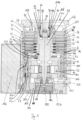
- the Fig.1 The vacuum pump shown comprises a pump inlet 70 surrounded by an inlet flange 68 and several pump stages for conveying the gas present at the pump inlet 70 through a pump channel 10 to a pump outlet (not shown), into which a Fig.1 shown outlet area 71.
- the outlet area 71 is the section of the pump channel 10 that is located at the downstream end of the inner Holweck stage.
- the vacuum pump comprises a Stator with a static housing 72 and a rotor arranged in the housing 72 with a rotor shaft 12 rotatably mounted about a rotation axis 14.
- the vacuum pump is designed as a turbomolecular pump and comprises a pump mechanism which is formed by several pump-effective turbomolecular pump stages connected in series with one another.
- the turbomolecular pump stages have several turbomolecular rotor disks 16 connected to the rotor shaft 12 and several turbomolecular stator disks 26 arranged in the axial direction between the rotor disks 16 and fixed in the housing 72.
- the stator disks 26 are held at a desired axial distance from one another by spacer rings 36.
- the rotor disks 16 and the stator disks 26 provide an axial pumping effect in a suction area 50 directed in the direction of the arrow 58, i.e. in the pumping direction.
- the pump channel 10 extends through the turbomolecular pump stages and further through a Holweck pump mechanism arranged downstream of the turbomolecular pump stages.
- the Holweck pump mechanism comprises Holweck pump stages arranged one inside the other in the radial direction and connected in series with one another for pumping purposes.
- the rotor-side part of the Holweck pump stages comprises a rotor hub 74 connected to the rotor shaft 12 and two cylinder-jacket-shaped Holweck rotor sleeves 76, 78 fastened to and carried by the rotor hub 74, which are oriented coaxially to the rotation axis 14 and nested one inside the other in the radial direction.
- two cylinder-jacket-shaped Holweck stator sleeves 80, 82 are provided, which are also oriented coaxially to the rotation axis 14 and nested one inside the other in the radial direction.
- the pumping surfaces of the Holweck pump stages are separated by the opposing surfaces forming a narrow radial Holweck gap.
- one of the pump-active surfaces is smooth - in this case that of the Holweck rotor sleeve 76 or 78 - and the opposite pump-active surface of the Holweck stator sleeve 80, 82 comprises a Holweck thread with grooves running helically around the rotation axis 14 in the axial direction, in which the gas is propelled and thus pumped by the rotation of the respective rotor sleeve 76, 78.
- a first Holweck gap 83a runs between the outer Holweck stator sleeve 80 and the outer Holweck rotor sleeve 76.
- a second Holweck gap 83b runs between the Holweck rotor sleeve 76 and the inner Holweck stator sleeve 82.
- a third Holweck gap 83c runs between the inner Holweck stator sleeve 82 and the inner Holweck rotor sleeve 78.
- the pump channel 10 opens into the outlet region 71, via which the gas conveyed from the inlet 70 is pumped into the outlet (not shown).
- a further gap 85a is provided, which opens into the outlet region 71 in shunt connection and connects the outlet region 71 to a labyrinth seal 130.
- the gap 85a is therefore not part of the pump channel 10.
- the gap 85a in which at least substantially no pumping function occurs during operation of the vacuum pump, is at least by a predetermined factor, e.g. 2 times, 3 times, 4 times, 5 times, 6 times, 7 times, 8 times, 9 times or 10 times, larger than each of the Holweck gaps 83a, 83b and 83c.
- the grooves essentially form the pump channel for the gas to be pumped.
- the Holweck pump stages provide a pumping effect, particularly due to the Holweck thread, in order to further convey the gas conveyed along the pump channel by the turbomolecular pump stages through the Holweck pump stages to the outlet.
- the rotatable bearing of the rotor shaft 12 is effected by a rolling bearing 84 in the area of the pump outlet and a permanent magnet bearing 86 in the area of the pump inlet 70.
- the permanent magnet bearing 86 comprises a rotor-side bearing half 88 and a stator-side bearing half 90, each of which comprises a ring stack of several permanent magnet rings 92, 94 stacked on top of one another in the axial direction.
- the magnet rings 92, 94 lie opposite one another, forming a radial bearing gap.
- the stator-side magnet rings 94 are carried by a stator-side carrier section that extends through the magnet rings 94 and is suspended from radial struts 108 of the housing 72.
- the stator-side magnet rings 94 are secured to the end of the magnet ring stack facing the inside of the pump by a compensating element 114 and a fastening ring 116.
- An emergency or safety bearing 98 is provided within the magnetic bearing 86, which is designed as an unlubricated roller bearing. During normal operation of the vacuum pump, the safety bearing 98 is in place. It only engages and rotates when there is an excessive radial deflection of the rotor relative to the stator in order to form a radial stop for the rotor, which prevents a collision of the rotor-side structures with the stator-side structures.
- a conical injection nut 100 with an outer diameter that increases towards the roller bearing 84 is provided on the rotor shaft 12.
- the injection nut 100 is in sliding contact with a scraper of a fluid reservoir, which comprises several absorbent disks 102 impregnated with a fluid, such as a lubricant.
- a fluid such as a lubricant.
- the fluid is transferred by capillary action from the fluid reservoir via the scraper to the rotating injection nut 100 and as a result of the Centrifugal force along the injection nut 100 in the direction of the increasing outer diameter to the roller bearing 84, where it fulfills a lubricating function, for example.
- the roller bearing 84 and the operating fluid reservoir are enclosed by a trough-shaped insert 124 and a cover element 126 of the vacuum pump.
- bearing for the rotor shaft 12 is also possible.
- a five-axis active magnetic bearing could be provided for the rotor shaft 12.
- the vacuum pump comprises a drive motor 104 designed as an electric motor for rotating the rotor, the rotor of which is formed by the rotor shaft 12.
- a control unit 106 controls the motor 104.
- Seals may be provided between individual components of the vacuum pump, some of which are designated by the reference numeral 107 for illustration purposes.
- the vacuum pump further comprises a sealing gas inlet 122 which is closed with a closure element 120 and which connects the bearing space provided in the vacuum pump for the rolling bearing 84 with the outside of the pump and via which a sealing gas can be supplied to the bearing space.
- a labyrinth seal 130 is formed in the area between the rotor hub 74 and a partition wall 128 through which the rotor shaft 12 extends, forming a radial gap.
- Such a labyrinth seal 130 is also referred to as a sealing gas labyrinth.
- the sealing gas labyrinth 130 is formed by a rotating surface 132 formed on the rotor hub 74 and a complementary fixed surface 134 formed on the partition wall 128.
- the surfaces 132 and 134 have interlocking, ring-shaped elevations, such as Fig.1 shows.
- the vacuum pump of the Fig.1 Five ring-shaped elevations are provided on each surface 132, 134, so that in this context one also speaks of a five-stage sealing gas labyrinth.
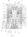
- the basic structure of the vacuum pump of the Fig.2 corresponds to the structure of the vacuum pump of the Fig.1
- the vacuum pump is Fig.2 further optimized with regard to reduced power consumption, in particular to keep the heating of the pump low during operation with air cooling, to reduce the power consumption of the vacuum pump and to enable higher gas loads with the same power consumption.
- the vacuum pump of the Fig.2 The inner Holweck rotor sleeve (see reference numeral 78 in Fig.1 ) is omitted, so that the vacuum pump of the Fig.2 only has two Holweck pump stages nested inside each other, which encompass the Holweck rotor sleeve 76.
- the Holweck stages By reducing the Holweck stages to two stages, for example, the gas friction can be reduced.
- the sealing gas labyrinth 130 is reduced to three stages by providing in the pump-active surface 134 on the side of the partition wall 128 instead of the five ring-shaped elevations (cf. Fig.1 ) only the three inner ring-shaped elevations are provided.
- the two outer labyrinth stages were omitted, since the relative speeds between the fixed partition 128 and the rotor hub 74 rotating during operation of the pump are the greatest and thus the gas friction losses are the highest.
- the gas friction can be reduced.
- the required power consumption of the electric motor 104 to achieve a certain final pressure can be reduced.
- the vacuum pump of the Fig.2 the electric motor 104 can have a package of electrical sheets coated with baking varnish and held together by baking varnish on both the stator side and the rotor side, so that the steel sheets of the respective package of steel sheets are only connected to one another by means of baking varnish and are not held together by welding or riveting.
- the rotor-side package of electrical sheets is in particular the iron return of the rotor of the electric motor 104.
- the electrical sheets are insulated from one another, which can reduce eddy current losses in the packages.
- each steel sheet of the package of steel sheets of the iron return of the rotor and/or the stator has a thickness of less than 0.4 mm, preferably less than 0.36 mm and particularly preferably a thickness of at least approximately 0.35 mm.
- the vacuum pump of the Fig.2 the remaining Holweck rotor sleeve 76 was positioned relative to the axial direction of the vacuum pump, for example to 46 mm, so that the remaining two Holweck pump stages result in a total pumping-active length of 92 mm.
- the short pumping-active length of the Holweck pump stages enables a further reduction in gas friction and thus in the required power consumption of the electric motor 104 to achieve a certain final pressure.
- the electric motor 104 was designed such that its maximum motor power is no more than 10 watts above the motor power required for the operating point and/or that it absorbs a drive voltage of 48 volts.
- the gaps through which the pump channel runs and which are located between a rotating and a stationary component of the vacuum pump, with the two components interacting to provide a pumping effect were designed in such a way that such gaps are at least a factor of about 5 smaller than those gaps in the vacuum pump in which no pumping effect occurs.
- All gaps in which no pumping effect occurs are in particular gaps through which the pump channel runs and/or gaps between a moving and a stationary component. However, they can also be gaps that are provided between two stationary components.
- both the Holweck gap 83a extending between the outer Holweck stator sleeve 80 and the outer Holweck rotor sleeve 76 and the Holweck gap 83b extending between the inner Holweck stator sleeve 82 and the outer Holweck rotor sleeve 76 were designed such that the gap 85 extending radially inside the Holweck stator sleeve 82 is larger by a factor of, e.g., 5 times, than the gap 83a and the gap 83b.
- the Holweck gaps 83a and 83b are designed such that at nominal speeds of the Holweck hub 74 they have a width of less than 0.3 mm. This leads to lower overflow losses in the Holweck pump stage and, in particular, to higher compression, which can improve the performance of the vacuum pump.
Landscapes
- Engineering & Computer Science (AREA)
- Mechanical Engineering (AREA)
- General Engineering & Computer Science (AREA)
- Non-Positive Displacement Air Blowers (AREA)
Description
- Die vorliegende Erfindung betrifft eine Vakuumpumpe, insbesondere Turbomolekularpumpe, mit wenigstens einem Pumpmechanismus zum Pumpen von Gas längs eines von einem Einlass zu einem Auslass der Vakuumpumpe verlaufenden Pumpkanals, wobei der Pumpkanal durch wenigstens einen ersten Spalt verläuft, in welchem beim Betrieb der Vakuumpumpe eine Pumpfunktion erfüllt wird, und wobei wenigstens ein zweiter Spalt vorgesehen ist, in welchem beim Betrieb der Vakuumpumpe keine Pumpfunktion erfüllt wird.
- Eine derartige Vakuumpumpe ist aus
EP 2 631 488 A2 bekannt. - Vakuumpumpen der eingangs genannten Art stellen üblicherweise eine hohe Kompression, einen hohen zulässigen Vorvakuumdruck und/oder kurze Hochlaufzeiten zur Minimierung von Prozess-Zykluszeiten bereit. Für einige Anwendungen ist es jedoch vorteilhaft, wenn eine Vakuumpumpe im Betrieb nur eine geringe Pumpenkörpertemperatur erreicht, hohe Gaslasten bewältigen kann, bei hohen Umgebungstemperaturen einsetzbar ist und/oder eine geringe Aufnahme an elektrischer Leistung, insbesondere bei Vorvakuumdrücken von 1 bis 10 mbar, aufweist.
- Der vorliegenden Erfindung liegt daher die Aufgabe zugrunde, eine verbesserte Vakuumpumpe bereitzustellen, die wenigstens einen der vorgenannten Vorteile bietet.
- Die Aufgabe wird durch eine Vakuumpumpe mit den Merkmalen des Anspruchs 1 gelöst.
- Der zweite Spalt, in dem während des Pumpenbetriebs keine Pumpfunktion bewirkt wird bzw. auftritt, ist somit im Vergleich zum ersten Spalt, in welchem beim Betrieb eine Pumpfunktion auftritt, bei der erfindungsgemäßen Vakuumpumpe verhältnismäßig groß ausgestaltet. Dadurch kann insbesondere die Gasreibung im Bereich des zweiten Spaltes gering gehalten werden. Im Vergleich zu einem kleiner ausgestalteten zweiten Spalt kann die erfindungsgemäße Pumpe somit einen bestimmten Enddruck unter Aufnahme einer geringeren elektrischen Leistung erreichen. Durch die reduzierte Leistungsaufnahme erwärmt sich die Vakuumpumpe im Betrieb weniger stark. Dadurch kann die Temperatur des Pumpenkörpers während des Betriebs der Vakuumpumpe niedrig gehalten werden, was bei manchen Anwendungen von Vorteil ist. Außerdem kann der erste Spalt, in dem während des Betriebs der Vakuumpumpe eine Pumpfunktion bewirkt wird und somit ein Pumpeffekt auftritt, derart klein ausgestaltet werden, dass eine bestimmungsgemäße Pumpfunktion, insbesondere eine ausreichend hohe Kompression bzw. ein ausreichend hohes Saugvermögen, durch die den ersten Spalt bildenden Bauteile bereitgestellt werden kann.
- Bei dem zweiten Spalt handelt es sich um einen Spalt, durch den der Pumpkanal verläuft. Dabei tritt im zweiten Spalt allerdings keine Pumpfunktion während des Betriebs der Vakuumpumpe auf. Indem der zweite Spalt verhältnismäßig groß im Vergleich zum ersten Spalt, in welchem beim Betrieb der Vakuumpumpe eine Pumpfunktion auftritt, ausgebildet ist, kann der Widerstand für das durch den zweiten Spalt zu fördernde Gas gering gehalten werden.
- Der zweite Spalt kann gemäß einem nicht erfindungsgemäßen Beispiel auch außerhalb des Pumpkanals liegen. Bei dem zweiten Spalt kann es sich beispielsweise um einen Spalt in einem Sperrgarlabyrinth handeln. Indem der zweite Spalt verhältnismäßig groß im Vergleich zum ersten Spalt ausgebildet wird, kann eine im zweiten Spalt auftretende Gasreibung gering gehalten werden. Dabei kann ein außerhalb des Pumpkanals vorgesehener zweiter Spalt insbesondere zwischen einem rotierenden und einem stehenden Bauteil angeordnet sein. Alternativ kann der zweite Spalt, insbesondere wenn er sich außerhalb des Pumpkanals befindet, zwischen zwei stehenden Bauteilen ausgebildet sein. Wenngleich der zweite Spalt nicht im Pumpkanal angeordnet sein kann, so kann zwischen dem zweiten Spalt und dem Pumpkanal eine gasleitende Verbindung bestehen, wie z.B. bei einem Sperrgaslabyrinth. Der zweite Spalt kann somit gewissermaßen in der Art eines Nebenschlusses an den Pumpkanal angeschlossen sein bzw. mit dem Pumpkanal in gasleitender Verbindung stehen.
- Bevorzugt bezieht sich der genannte Faktor, der das Größenverhältnis zwischen dem ersten und zweiten Spalt angibt, auf die Breite des ersten bzw. zweiten Spalts. Der zweite Spalt weist somit eine Breite auf, die größer ist als die Breite des ersten Spalts multipliziert mit dem Faktor. Dabei wird die Spaltbreite vorzugsweise senkrecht zur Förderrichtung des zu pumpenden Gases durch den Spalt gemessen.
- Bevorzugt ist mit dem Begriff "Spalt" nicht ein in Pumprichtung des zu fördernden Gases gesehen beliebig kurzer Freiraum bzw. eine beliebig kurze Lücke z.B. zwischen zwei Bauteilen der Vakuumpumpe gemeint, sondern ein jeweiliger Abschnitt, z.B. des Pumpkanals und/oder zwischen zwei Bauteilen, der sich, insbesondere mit zumindest im Wesentlichen gleichbleibender Breite, zumindest über eine vorgegebene Länge, z.B. von wenigstens 5 mm oder von wenigstens 10 mm oder von wenigstens 15 mm, erstreckt.
- Mit der Formulierung, dass im ersten Spalt eine Pumpfunktion erfüllt bzw. bewirkt wird, ist insbesondere gemeint, dass während des Pumpenbetriebs in dem Spalt ein Pumpeffekt bzw. eine Pumpwirkung auftritt. Das zu pumpende Gas wird somit aktiv durch den Spalt gefördert und strömt nicht nur längs des Pumpkanals vom Spalteingang zum Spaltausgang.
- Der erste Spalt ist zwischen einem rotierenden Bauteil und einem stehenden Bauteil der Vakuumpumpe vorgesehen, wobei die beiden Bauteile während des Pumpenbetriebs derart zusammenwirken, dass sie im ersten Spalt die Pumpfunktion bewirken. Durch das Zusammenspiel des rotierenden und des stehenden Bauteils wird somit im ersten Spalt die Pumpwirkung erzielt.
- Der zweite Spalt ist zwischen zwei Bauteilen der Vakuumpumpe vorgesehen, die im Betrieb der Pumpe nicht derart zusammenwirken, dass sie eine Pumpfunktion erfüllen. Es handelt sich bei den beiden Bauteilen, zwischen denen der zweite Spalt vorgesehen ist, um ein rotierendes und ein stehendes Bauteil. Die beiden Bauteile erfüllen dabei allerdings keine Pumpfunktion im Bereich des zweiten Spalts. Alternativ kann es sich gemäß einem nicht erfindungsgemäßen Beispiel bei den beiden Bauteilen auch um statische Bauteile handeln.
- Nach einer Ausgestaltung der Erfindung sind alle Spalte, in denen keine Pumpfunktion erfüllt wird, um zumindest den Faktor größer sind als diejenigen Spalte, durch die der Pumpkanal verläuft und in denen eine Pumpfunktion erfüllt wird. Dadurch kann die Gasreibung längs des Pumpkanals effektiv verringert und die Leistungsaufnahme der Vakuumpumpe zum Erreichen eines bestimmten Enddrucks reduziert werden, insbesondere wenn die Spalte, in denen keine Pumpfunktion auftritt, im Pumpkanal angeordnet sind bzw. der Pumpkanal durch diese Spalte verläuft.
- Der erste Spalt ist ein Holweckspalt, der zwischen einer pumpaktiven Oberfläche eines Holweck-Rotors und einer pumpaktiven Oberfläche eines Holweck-Stators ausgebildet ist.
- Bei dem zweiten Spalt handelt es sich beispielsweise um einen Spalt zwischen einer glatten Seite eines Holweck-Rotors, die bspw. die Rückseite zu einer pumpaktiven Oberfläche des Holweck-Rotors bildet, und einer gegenüberstehenden glatten Oberfläche eines stehenden Bauteils, so dass sich bei rotierendem Holweck-Rotor zwischen der glatten Rückseite des Holweck-Rotors und der glatten Oberfläche des stehenden Bauteils kein oder allenfalls nur ein geringer Pumpeffekt einstellt.
- Nach einer weiteren Ausgestaltung der Erfindung umfasst der Pumpmechanismus einen Holweck-Pumpmechanismus mit einem Holweck-Rotor und einem Holweck-Stator umfasst, wobei der erste Spalt ein Holweck-Spalt ist, der zwischen der Mantelfläche des Holweck-Stators und der Mantelfläche des Holweck-Rotors vorgesehen ist, und wobei der Holweck-Spalt, insbesondere bei Nenndrehzahlen des Holweck-Pumpmechanismus, eine Breite von weniger als 0,5 mm, bevorzugt von weniger als 0,3 mm, aufweist.
- Insbesondere aufgrund des engen Holweck-Spalts kann ein frühzeitiges Absperren des Holweck-Pumpmechanismus bei hohen Vorvakuumdrücken, die im Bereich des Auslasses auftreten können, erreicht werden. Außerdem können geringere Überströmverluste im Bereich des Holweck-Spalts realisiert werden, wodurch das Kompressionsvermögen des Holweck-Pumpmechanismus verbessert werden kann.
- Vorzugsweise kommt ein derart schmaler Holweck-Spalt bei einer Vakuumpumpe zum Einsatz, deren Einlass einen Einlassflansch mit einem Durchmesser von DN 100 oder DN 160 aufweist.
- Nach einer bevorzugten Weiterbildung der Erfindung umfasst der Pumpmechanismus einen Holweck-Pumpmechanismus mit nur einer einzigen Holweck-Stufe oder mit maximal zwei Holweck-Stufen.
- Dabei kann es vorgesehen sein, dass die Vakuumpumpe, insbesondere vom Bauraum her gesehen, für mehr als zwei, insbesondere ineinander geschachtelte, Holweck-Stufen ausgelegt ist, aber tatsächlich nur eine Holweck-Stufe oder maximal zwei Holweck-Stufen realisiert sind, während die übrigen Holweck-Stufen nicht realisiert sind, z.B. durch Auslassen der Holweckstufe oder durch Weglassen eines von zwei Holweck-Rotoren.
- Vorzugsweise weist der Pumpmechanismus einen Holweck-Pumpmechanismus auf, dessen pumpaktive Oberfläche, insbesondere längs der axialen Richtung der Pumpe gesehen, eine Gesamtlänge aufweist, die geringer als 120 mm, bevorzugt geringer als 95 mm ist. Dadurch kann die Gasreibung im Holweck-Pumpenmechanismus vermindert werden, wodurch eine geringere elektrische Leistungsaufnahme der Vakuumpumpe erforderlich ist.
- Nach einer Weiterbildung der Erfindung weist der Holweck-Pumpmechanismus wenigstens einen und bevorzugt genau einen Holweck-Rotor auf, dessen Länge in axialer Richtung der Pumpe gesehen maximal 60 mm, bevorzugt maximal 55 mm, weiter bevorzugt maximal 48 mm, beträgt. Der Holweck-Pumpmechanismus kann somit in axialer Richtung betrachtet verhältnismäßig kurz ausgestaltet sein, wodurch eine geringere Gasreibung im Holweck-Pumpmechanismus bewirkt wird. Dies wirkt sich vorteilhaft auf die erforderliche elektrische Leistungsaufnahme der Vakuumpumpe zum Erreichen eines bestimmten Enddrucks aus.
- Nach einer weiteren Ausgestaltung der Erfindung weist der Pumpmechanismus wenigstens eine turbomolekulare Pumpstufe mit mehreren an einer Rotorwelle befestigten Rotorscheiben und in axialer Richtung zwischen den Rotorscheiben drehfest angeordneten Statorscheiben auf, wobei sich der Pumpkanal durch die turbomolekulare Pumpstufe erstreckt, und wobei in der turbomolekularen Pumpstufe wenigstens eine Rotorscheibe und/oder wenigstens eine Statorscheibe weggelassen ist, so dass die Pumpstufe an der Stelle der weggelassenen Rotorscheibe bzw. Statorscheibe einen Freiraum aufweist.
- Die Vakuumpumpe bietet somit Bauraum für mehr Rotor- und/oder Statorscheiben als tatsächlich in der Vakuumpumpe verbaut sind und weist anstelle der weggelassenen Scheiben einen entsprechenden Freiraum auf. Durch das Weglassen der Rotor- und/oder Statorscheiben kann die Gasreibung in der turbomolekularen Pumpstufe verringert werden. Der ordnungsgemäße Betrieb der Vakuumpumpe kann somit unter geringerer Leistungsaufnahme erfolgen, wodurch eine übermäßige Erwärmung der Vakuumpumpe vermieden und der Stromverbrauch der Vakuumpumpe gesenkt werden kann.
- Vorzugsweise ist wenigstens ein Scheibenpaar, bestehend aus einer Rotorscheibe und der benachbarten, mit der Rotorscheibe zusammenwirkenden Statorscheibe, weggelassen. Insbesondere handelt es sich bei dem weggelassenen Scheibenpaar um das in Richtung Vorvakuum liegende äußerste Scheibenpaar der turbomolekularen Pumpstufe, da durch Weglassen dieses Scheibenpaares ein guter Kompromiss zwischen einer Reduzierung der Gasreibung einerseits und einer Verminderung des Saug- bzw. Kompressionsvermögens der turbomolekularen Pumpstufe andererseits erzielt werden kann.
- Bevorzugt weisen die Rotorscheiben und/oder die Statorscheiben wenigstens einer turbomolekularen Pumpstufe eine ballige Scheibengeometrie auf. Alternativ kann eine abgesetzte Scheibengeometrie vorgesehen sein.
- Nach einer Weiterbildung der Erfindung umfasst die Vakuumpumpe wenigstens eine und bevorzugt genau eine einzige turbomolekulare Pumpstufe, die mit maximal 6 Rotorscheiben ausgestattet ist, wobei ein am Einlass der Vakuumpumpe vorgesehener Flansch einen Flanschdurchmesser von DN 100 aufweist.
- Nach einer anderen Weiterbildung der Erfindung umfasst die Vakuumpumpe wenigstens eine und bevorzugt genau eine einzige turbomolekulare Pumpstufe, die mit maximal 4 Rotorscheiben ausgestattet ist, wobei ein am Einlass der Vakuumpumpe vorgesehener Flansch einen Flanschdurchmesser von DN 160 aufweist.
- Nach einer weiteren Ausgestaltung der Erfindung weist die Vakuumpumpe einen Elektromotor zum Antreiben des Pumpmechanismus auf, wobei der Elektromotor einen Stator und einen mit dem Stator zusammenwirkenden, um eine Drehachse drehbaren Rotor aufweist, wobei der Stator ein Paket von Stahlblechen und/oder der Eisenrückschluss des Rotors ein Paket von Stahlblechen aufweist, und wobei die Stahlbleche des Pakets von Stahlblechen des Eisenrückschlusses des Rotors und/oder des Stators mittels Backlack miteinander verbunden und nicht miteinander verschweißt oder vernietet sind.
- Das Paket von Stahlblechen des Rotors und/oder des Stators wird somit ausschließlich durch Backlack zusammengehalten, sodass - insbesondere weil auf Verschweißungen und Vernietungen verzichtet wird - während des Betriebs des Elektromotors in dem jeweiligen Stahlblechpaket Wirbelstromverluste minimiert werden können. Dadurch kann die Erwärmung des Elektromotors und damit einhergehend die Erwärmung der Vakuumpumpe während ihres Betriebs verringert werden. Außerdem kann die erforderliche elektrische Leistungsaufnahme des Elektromotors zum Erreichen eines bestimmten Enddrucks reduziert werden.
- Bei den Stahlblechen handelt es sich insbesondere um Eisenbleche oder um Elektrobleche.
- Nach einer Ausgestaltung der Erfindung weist jedes Stahlblech des Pakets von Stahlblechen des Rotors und/oder des Stators eine Dicke von weniger als 0,4 mm, vorzugsweise von weniger als 0,36 mm, auf. Mit derart dünn ausgestalteten Blechen können Wirbelstromverluste im Stahlblechpaket des Rotors und/oder des Stators besonders gering gehalten werden.
- Bevorzugt weist der Elektromotor eine maximale Motorleistung auf, die um einen vorgegebenen Wert, insbesondere um zumindest im Wesentlichen 10 Watt, über der für den bestimmungsgemäßen Betrieb der Vakuumpumpe vorgesehenen Motorleistung liegt. Der Elektromotor weist somit eine verhältnismäßig geringe Antriebsleistung auf, insbesondere im Vergleich zu nach dem Stand der Technik in Vakuumpumpen eingesetzten Elektromotoren, die für eine möglichst kurze Hochlaufzeit ausgelegt sind und somit temporär weit mehr als 10 Watt über der für den Betriebspunkt erforderlichen Motorleistung bereitstellen können.
- Die Reduzierung der maximalen Motorleistung auf den vorgegebenen Wert, wie z.B. 10 Watt, über der für den bestimmungsgemäßen Betrieb der Vakuumpumpe vorgesehenen Motorleistung weist insbesondere den Vorteil auf, dass der Elektromotor kompakt ausgebildet werden kann und während des Betriebs des Elektromotors auftretende Wirbelstromverluste reduziert werden können. Außerdem kann der Einsatz von Kupfer, das insbesondere auf der Seite des Rotors zur Bildung von elektrischen Wicklungen verwendet wird, reduziert werden.
- Der Elektromotor kann für eine Antriebsspannung von zumindest annähernd 48 Volt ausgelegt sein. Bei aus dem Stand der Technik bekannten Vakuumpumpen sind die Elektromotoren normalerweise für eine Antriebsspannung von 24 Volt ausgelegt, sodass bei der erfindungsgemäßen Variante des Elektromotors die Antriebsspannung auf zumindest annähernd 48 Volt gegenüber der normalen Antriebsspannung von 24 Volt verdoppelt ist. Bevorzugt ist dabei die maximale Antriebsspannung gleich der Sicherheitskleinspannung von 50 Volt im Gleisspannungsbetrieb (50 Volt DC). Die Verdoppelung der Antriebsspannung von 24 Volt auf 48 Volt führt bei gleicher Leistungsaufnahme zu einer Halbierung der durch den Elektromotor fließenden Ströme und damit auch zu einer Verringerung von Antriebsverlusten.
- Nach einer bevorzugten Weiterbildung der Erfindung weist die Vakuumpumpe ein Sperrgaslabyrinth mit maximal drei Labyrinthstufen auf. Die Vakuumpumpe kann dabei für mehr als drei Labyrinthstufen ausgelegt sein, wobei die Reduzierung auf maximal drei Labyrinthstufen dadurch erreicht wird, dass weitere Labyrinthstufen weggelassen und somit - trotz des dafür vorgesehenen Bauraums - nicht verbaut wurden. Zur Minimierung der Gasreibung werden dabei bevorzugt diejenigen Labyrinthstufen weggelassen, die den größten Durchmesser haben, da bei diesen die Relativgeschwindigkeiten zwischen dem Rotor und dem Stator des Sperrgaslabyrinths am größten und damit die Reibungsverluste am höchsten sind.
- Die Reduzierung der Labyrinthstufen kann insbesondere dadurch erreicht werden, dass das Sperrgaslabyrinth von einer rotierenden Oberfläche, beispielsweise der Oberfläche eines sich in radialer Richtung erstreckenden Teils der Nabe eines Holweck-Rotors, und einer feststehenden Oberfläche, beispielsweise der der Rotornabe gegenüberstehenden Oberfläche, gebildet wird, und dass die beiden Oberflächen ineinandergreifende, ringförmige Erhöhungen aufweisen, wobei eine der Oberflächen mehr Erhöhungen aufweist als die andere Oberfläche.
- Nach einer weiteren Ausgestaltung der Erfindung ist im Betrieb der Vakuumpumpe vorgesehen, dass ein geringer Sperrgasfluss, der insbesondere unterhalb einer vorgegebenen Schwelle liegt, insbesondere unter 15 sccm, durch das Sperrgaslabyrinth strömt. Dadurch kann eine Absenkung der Rotortemperatur erreicht und die im Betrieb der Pumpe auftretende Erwärmung reduziert werden.
- Nach einer weiteren Ausgestaltung der Erfindung kann anstelle eines Sperrgarlabyrinths eine Gaede- oder Siegbahnstufe eingesetzt werden.
- Vorteilhaft an Ausführungsformen einer erfindungsgemäßen Vakuumpumpe ist insbesondere, dass deren maximale Leistungsaufnahme gegenüber aus dem Stand der Technik bekannten Vakuumpumpen reduziert ist, insbesondere durch Maßnahmen, die zu einer Verringerung der Wirbelstromverluste im Elektromotor und der Gasreibung des durch die Vakuumpumpe geförderten Gases führen. Eine übermäßige Erwärmung der Vakuumpumpe während des Betriebs kann somit vermieden werden, so dass Ausführungsformen der erfindungsgemäßen Vakuumpumpe in Kombination mit einer Luftkühlung anstatt mit einer deutlich aufwändigeren Wasserkühlung verwendet werden können. Außerdem ist ein luftgekühlter Einsatz bei höheren Umgebungstemperaturen, von z.B. größer als 40° C, möglich. Ferner können höhere Gaslasten bei gleicher Leistungsaufnahme bewältigt werden.
- Nachfolgend werden nicht erfindungsgemäße Vakuumpumpen beispielhaft unter Bezugnahme auf die beigefügten Figuren beschrieben. Es zeigen, jeweils schematisch:
- Fig. 1
- eine Querschnittsansicht einer Variante einer Vakuumpumpe, und
- Fig. 2
- eine Querschnittsansicht einer weiteren Variante einer Vakuumpumpe.
- Die in
Fig. 1 gezeigte Vakuumpumpe umfasst einen von einem Einlassflansch 68 umgebenen Pumpeneinlass 70 sowie mehrere Pumpstufen zur Förderung des an dem Pumpeneinlass 70 anstehenden Gases durch einen Pumpkanal 10 zu einem nicht dargestellten Pumpenauslass, in welchen ein inFig. 1 gezeigter Auslassbereich 71 mündet. Bei dem Auslassbereich 71 handelt es sich bei dem dargestellten Beispiel um denjenigen Abschnitt des Pumpkanals 10, der am stromabwärtigen Ende der inneren Holweck-Stufe liegt. Die Vakuumpumpe umfasst einen Stator mit einem statischen Gehäuse 72 und einen in dem Gehäuse 72 angeordneten Rotor mit einer um eine Rotationsachse 14 drehbar gelagerten Rotorwelle 12. - Die Vakuumpumpe ist als Turbomolekularpumpe ausgebildet und umfasst einen Pumpmechanismus, der von mehreren pumpwirksamen miteinander in Serie geschalteten, turbomolekularen Pumpstufen gebildet wird. Die turbomolekularen Pumpstufen weisen mehrere mit der Rotorwelle 12 verbundene turbomolekulare Rotorscheiben 16 und mehrere in axialer Richtung zwischen den Rotorscheiben 16 angeordnete und in dem Gehäuse 72 festgelegte turbomolekulare Statorscheiben 26 auf. Die Statorscheiben 26 werden durch Distanzringe 36 in einem gewünschten axialen Abstand zueinander gehalten. Die Rotorscheiben 16 und die Statorscheiben 26 stellen in einem Schöpfbereich 50 eine in Richtung des Pfeils 58, also in Pumprichtung, gerichtete axiale Pumpwirkung bereit. Der Pumpkanal 10 erstreckt sich durch die turbomolekularen Pumpstufen und weiter durch einen den turbomolekularen Pumpstufen nachgeordneten Holweck-Pumpmechanismus hindurch.
- Der Holweck-Pumpmechanismus umfasst in radialer Richtung ineinander angeordnete und pumpwirksam miteinander in Serie geschaltete Holweck-Pumpstufen. Der rotorseitige Teil der Holweck-Pumpstufen umfasst eine mit der Rotorwelle 12 verbundene Rotornabe 74 und zwei an der Rotornabe 74 befestigte und von dieser getragene zylindermantelförmige Holweck-Rotorhülsen 76, 78, die koaxial zu der Rotationsachse 14 orientiert und in radialer Richtung ineinandergeschachtelt sind. Ferner sind zwei zylindermantelförmige Holweck-Statorhülsen 80, 82 vorgesehen, die ebenfalls koaxial zu der Rotationsachse 14 orientiert und in radialer Richtung ineinandergeschachtelt sind.
- Die pumpaktiven Oberflächen der Holweck-Pumpstufen sind durch die einander unter Ausbildung eines engen radialen Holweck-Spalts gegenüberliegenden radialen Mantelflächen einer Holweck-Rotorhülse 76, 78 und einer Holweck-Statorhülse 80, 82 gebildet. Dabei ist jeweils eine der pumpaktiven Oberflächen glatt ausgebildet - vorliegend diejenige der Holweck-Rotorhülse 76 bzw. 78 - und die gegenüberliegende pumpaktive Oberfläche der Holweck-Statorhülse 80, 82 umfasst ein Holweck-Gewinde mit schraubenlinienförmig um die Rotationsachse 14 herum in axialer Richtung verlaufenden Nuten, in denen durch die Rotation der jeweiligen Rotorhülse 76, 78 das Gas vorangetrieben und dadurch gepumpt wird.
- Wie
Fig. 1 zeigt, verläuft ein erster Holweck-Spalt 83a zwischen der äußeren Holweck-Statorhülse 80 und der äußeren Holweck-Rotorhülse 76. Ein zweiter Holweck-Spalt 83b verläuft zwischen der Holweck-Rotorhülse 76 und der inneren Holweck-Statorhülse 82. Ein dritter Holweck-Spalt 83c verläuft zwischen der inneren Holweck-Statorhülse 82 und der inneren Holweck-Rotorhülse 78. Am stromabwärtigen Ende des Holweck-Spalts 83c mündet der Pumpkanal 10 in den Auslassbereich 71, über den das vom Einlass 70 geförderte Gas in den Auslass (nicht gezeigt) gepumpt wird. Radial innerhalb der inneren Holweck-Rotorhülse 78 ist ein weiterer Spalt 85a vorgesehen, der im Nebenschluss in den Auslassbereich 71 mündet und den Auslassbereich 71 mit einer Labyrinthdichtung 130 verbindet. Der Spalt 85a ist somit nicht Teil des Pumpkanals 10. - Bei der dargestellten Variante ist der Spalt 85a, in welchem beim Betrieb der Vakuumpumpe zumindest im Wesentlichen keine Pumpfunktion auftritt, zumindest um einen vorgegebenen Faktor, z.B. 2-mal, 3-mal, 4-mal, 5-mal, 6-mal, 7-mal, 8-mal, 9-mal oder 1 0-mal, größer als jeder der Holweck-Spalte 83a, 83b und 83c.
- Im Bereich der jeweiligen Holweck-Pumpstufe bilden im Wesentlichen die Nuten den Pumpkanal für das zu pumpende Gas. Die Holweck-Pumpstufen stellen dabei, insbesondere aufgrund des Holweck-Gewindes, eine Pumpwirkung bereit, um das längs des Pumpkanals von den turbomolekularen Pumpstufen geförderte Gas weiter durch die Holweck-Pumpstufen hindurch zum Auslass zu fördern.
- Die drehbare Lagerung der Rotorwelle 12 wird durch ein Wälzlager 84 im Bereich des Pumpenauslasses und ein Permanentmagnetlager 86 im Bereich des Pumpeneinlasses 70 bewirkt.
- Das Permanentmagnetlager 86 umfasst eine rotorseitige Lagerhälfte 88 und eine statorseitige Lagerhälfte 90, welche jeweils einen Ringstapel aus mehreren in axialer Richtung aufeinandergestapelten permanentmagnetischen Ringen 92, 94 umfassen. Die Magnetringe 92, 94 liegen dabei unter Ausbildung eines radialen Lagerspalts einander gegenüber. Die statorseitigen Magnetringe 94 werden von einem statorseitigen Trägerabschnitt getragen, der sich durch die Magnetringe 94 hindurch erstreckt und an radialen Streben 108 des Gehäuses 72 aufgehängt ist. Die statorseitigen Magnetringe 94 sind am zum Pumpeninneren hingewandten Ende des Magnetringstapels durch ein Ausgleichselement 114 sowie einen Befestigungsring 116 festgelegt.
- Innerhalb des Magnetlagers 86 ist ein Not- bzw. Fanglager 98 vorgesehen, welches als ungeschmiertes Wälzlager ausgebildet ist. Im normalen Betrieb der Vakuumpumpe steht das Fanglager 98. Es gelangt erst bei einer übermäßigen radialen Auslenkung des Rotors gegenüber dem Stator in Eingriff und in Rotation, um einen radialen Anschlag für den Rotor zu bilden, der eine Kollision der rotorseitigen Strukturen mit den statorseitigen Strukturen verhindert.
- Im Bereich des Wälzlagers 84 ist an der Rotorwelle 12 eine konische Spritzmutter 100 mit einem zu dem Wälzlager 84 hin zunehmenden Außendurchmesser vorgesehen. Die Spritzmutter 100 steht mit einem Abstreifer eines Betriebsmittelspeichers in gleitendem Kontakt, der mehrere mit einem Betriebsmittel, wie zum Beispiel einem Schmiermittel, getränkte saugfähige Scheiben 102 umfasst. Im Betrieb wird das Betriebsmittel durch kapillare Wirkung von dem Betriebsmittelspeicher über den Abstreifer auf die rotierende Spritzmutter 100 übertragen und infolge der Zentrifugalkraft entlang der Spritzmutter 100 in Richtung des größer werdenden Außendurchmessers zu dem Wälzlager 84 hin gefördert, wo es zum Beispiel eine schmierende Funktion erfüllt. Das Wälzlager 84 und der Betriebsmittelspeicher sind durch einen wannenförmigen Einsatz 124 und ein Deckelelement 126 der Vakuumpumpe eingefasst.
- Es ist aber auch eine anders gestaltete Lagerung der Rotorwelle 12 möglich. Beispielsweise könnte eine Fünfachsig-Aktiv-Magnetlagerung für die Rotorwelle 12 vorgesehen sein.
- Die Vakuumpumpe umfasst einen als Elektromotor ausgestalteten Antriebsmotor 104 zum drehenden Antreiben des Rotors, dessen Läufer durch die Rotorwelle 12 gebildet ist. Eine Steuereinheit 106 steuert den Motor 104 an.
- Zwischen einzelnen Komponenten der Vakuumpumpe können Dichtungen vorgesehen sein, von denen zur Illustration einige Dichtungen mit dem Bezugszeichen 107 bezeichnet sind.
- Die Vakuumpumpe umfasst ferner einen mit einem Verschlusselement 120 verschlossenen Sperrgaseinlass 122, welcher den in der Vakuumpumpe vorgesehenen Lagerraum für das Wälzlager 84 mit dem Pumpenäußeren verbindet und über den dem Lagerraum ein Sperrgas zuführbar ist.
- Im Bereich zwischen der Rotornabe 74 und einer Trennwand 128, durch die sich die Rotorwelle 12 unter Ausbildung eines radialen Spalts hindurcherstreckt, ist eine Labyrinthdichtung 130 ausgebildet. Eine derartige Labyrinthdichtung 130 wird auch als Sperrgaslabyrinth bezeichnet. Das Sperrgaslabyrinth 130 wird von einer rotierenden Oberfläche 132, die an der Rotornabe 74 ausgebildet ist, und einer komplementären feststehenden Oberfläche 134, die an der Trennwand 128 ausgebildet ist, gebildet.
- Die Oberflächen 132 und 134 weisen ineinandergreifende, ringförmig ausgestaltete Erhöhungen auf, wie
Fig. 1 zeigt. Bei der Vakuumpumpe derFig. 1 sind auf jeder Oberfläche 132, 134 fünf ringförmige Erhöhungen vorgesehen, sodass in diesem Zusammenhang auch von einem fünfstufigen Sperrgaslabyrinth gesprochen wird. - Der Grundaufbau der Vakuumpumpe der
Fig. 2 entspricht dem Aufbau der Vakuumpumpe derFig. 1 . Allerdings ist die Vakuumpumpe derFig. 2 im Hinblick auf eine reduzierte Leistungsaufnahme noch weiter optimiert, insbesondere um die Erwärmung der Pumpe während des Betriebs bei Luftkühlung niedrig zu halten, um den Stromverbrauch der Vakuumpumpe zu senken und um höhere Gaslasten bei gleicher Leistungsaufnahme zu ermöglichen. - Dies wird insbesondere dadurch erreicht, dass bei der Vakuumpumpe der
Fig. 2 in der vom Pumpeneinlass 70 abgewandten turbomolekularen Pumpstufe das am weitesten entfernt vom Pumpeneinlass 70 liegende Paar bestehend aus einer Rotorscheibe 16 und einer Statorscheibe 26 weggelassen wurde, sodass an der Stelle der weggelassenen Scheiben ein Freiraum 136 gebildet ist. Durch das Weglassen des Scheibenpaares entfällt die an diesem Scheibenpaar auftretende Gasreibung aufgrund der Förderung des Gases längs des durch die Pumpstufe verlaufenden Pumpkanals 10, wodurch eine geringere Leistungsaufnahme des Elektromotors 104 erforderlich ist. - Bei der Vakuumpumpe der
Fig. 2 wurde die innere Holweck-Rotorhülse (vgl. das Bezugszeichen 78 inFig. 1 ) weggelassen, sodass die Vakuumpumpe derFig. 2 nur noch zwei ineinander geschachtelte, die Holweck-Rotorhülse 76 umfassende Holweck-Pumpstufen aufweist. Durch die Reduzierung der Holweckstufen auf z.B. zwei Stufen kann die Gasreibung reduziert werden. - Wie die
Fig. 2 außerdem zeigt, ist bei der Vakuumpumpe derFig. 2 das Sperrgaslabyrinth 130 auf drei Stufen reduziert, indem in der pumpaktiven Oberfläche 134 auf Seiten der Trennwand 128 anstelle der fünf ringförmigen Erhebungen (vgl.Fig. 1 ) nur noch die drei inneren ringförmigen Erhebungen vorgesehen sind. Es wurde somit zur Minimierung der Gasreibung im Sperrgaslabyrinth 130 auf die beiden äußeren Labyrinthstufen verzichtet, da bei diesen die Relativgeschwindigkeiten zwischen der feststehenden Trennwand 128 und der im Betrieb der Pumpe rotierenden Rotornabe 74 am größten und damit die Gasreibungsverluste am höchsten sind. Durch das Weglassen von Sperrgaslabyrinthstufen kann somit die Gasreibung reduziert werden. Außerdem lässt sich die erforderliche Leistungsaufnahme des Elektromotors 104 zum Erreichen eines bestimmten Enddrucks reduzieren. - Bei der Vakuumpumpe der
Fig. 2 kann der Elektromotor 104 sowohl statorseitig als auch rotorseitig ein Paket von mit Backlack überzogenen und durch Backlack zusammengehaltenen Elektroblechen aufweisen, sodass die Stahlbleche des jeweiligen Pakets von Stahlblechen nur mittels Backlack miteinander verbunden und nicht durch Verschweißen oder Vernieten zusammengehalten werden. Bei dem rotorseitigen Paket von Elektroblechen handelt es sich insbesondere um den Eisenrückschluss des Rotors des Elektromotors 104. Durch die Beschichtung der Elektrobleche mit Backlack sind die Elektrobleche gegeneinander isoliert, wodurch Wirbelstromverluste in den Paketen reduziert werden können. Eine weitere Reduzierung der Wirbelstromverluste wird dadurch erreicht, dass jedes Stahlblech des Pakets von Stahlblechen des Eisenrückschlusses des Rotors und/oder des Stators eine Dicke von weniger als 0,4 mm, vorzugsweise von weniger als 0,36 mm und besonders bevorzugt eine Dicke von zumindest annähernd 0,35 mm, aufweist. - Bei der Vakuumpumpe der
Fig. 2 wurde außerdem die verbleibende Holweck-Rotorhülse 76 bezogen auf die axiale Richtung der Vakuumpumpe, beispielsweise auf 46 mm, verkürzt, sodass sich insgesamt aufgrund der verbliebenen zwei Holweckpumpstufen eine pumpaktive Länge von 92 mm ergibt. Durch die kurze pumpaktive Länge der Holweckpumpstufen kann eine weitere Reduzierung der Gasreibung und damit der erforderlichen Leistungsaufnahme des Elektromotors 104 zum Erreichen eines bestimmten Enddrucks erreicht werden. - Ferner wurde der Elektromotor 104 so ausgelegt, dass seine maximale Motorleistung höchstens 10 Watt über der für den Betriebspunkt erforderlichen Motorleistung liegt und/oder dass er eine Antriebsspannung von 48 Volt aufnimmt.
- Bei der Vakuumpumpe der
Fig. 2 wurden außerdem diejenigen Spalte, durch die der Pumpkanal verläuft und die sich jeweils zwischen einem rotierenden und einem stehenden Bauteil der Vakuumpumpe befinden, wobei die beiden Bauteile derart zusammenwirken, dass sie eine Pumpwirkung bereitstellen, derart ausgelegt, dass derartige Spalte zumindest um einen Faktor, etwa 5-mal, kleiner sind als diejenigen Spalte der Vakuumpumpe, in denen kein Pumpeffekt auftritt. Bei sämtlichen Spalte, in denen kein Pumpeffekt auftritt, handelt es sich insbesondere um Spalte, durch die der Pumpkanal verläuft und/oder um Spalte zwischen einem beweglichen und einem stationären Bauteil. Es kann sich aber auch um Spalte handeln, die zwischen zwei jeweils stationären Bauteilen vorgesehen sind. - Beispielsweise wurde sowohl der zwischen der äußeren Holweck-Statorhülse 80 und der äußeren Holweck-Rotorhülse 76 verlaufende Holweck-Spalt 83a als auch der zwischen der inneren Holweck-Statorhülse 82 und der äußeren Holweck-Rotorhülse 76 verlaufende Holweckspalt 83b so ausgelegt, dass der sich radial innerhalb der Holweck-Statorhülse 82 erstreckende Spalt 85 um den Faktor, z.B. 5-mal, größer ist als der Spalt 83a und der Spalt 83b.
- Besonders vorteilhaft ist es außerdem, wenn die Holweck-Spalte 83a und 83b derart ausgelegt sind, dass sie bei Nenndrehzahlen der Holweck-Nabe 74 eine Breite von weniger als 0,3 mm aufweisen. Dies führt zu geringeren Überströmverlusten in der Holweck-Pumpstufe und insbesondere auch zu höherer Kompression, wodurch die Leistungsfähigkeit der Vakuumpumpe verbessert werden kann.
-
- 10
- Pumpkanal
- 12
- Rotorwelle
- 14
- Rotationsachse
- 16
- Rotorscheibe
- 26
- Statorscheibe
- 36
- Distanzring
- 50
- Schöpfbereich
- 58
- Pfeil
- 68
- Einlassflansch
- 70
- Pumpeneinlass
- 71
- Auslassbereich
- 72
- Gehäuse
- 74
- Rotornabe
- 76, 78
- Holweck-Rotorhülse
- 80, 82
- Holweck-Statorhülse
- 83a, 83b, 83c
- Holweck-Spalt
- 84
- Wälzlager
- 85
- Spalt
- 85a
- Spalt
- 86
- Permanentmagnetlager
- 88
- rotorseitige Lagerhälfte
- 90
- statorseitige Lagerhälfte
- 92, 94
- permanentmagnetischer Ring
- 98
- Fanglager
- 100
- Spritzmutter
- 102
- saugfähige Scheibe
- 104
- Antriebsmotor
- 106
- Steuereinheit
- 107
- Dichtung
- 108
- Strebe
- 114
- Ausgleichselement
- 116
- Befestigungsring
- 120
- Verschlusselement
- 122
- Sperrgaseinlass
- 124
- Einsatz
- 126
- Deckelelement
- 128
- Trennwand
- 130
- Labyrinthdichtung
- 132, 134
- pumpaktive Oberfläche
- 136
- Freiraum
Claims (9)
- Vakuumpumpe, insbesondere Turbomolekularpumpe, mitwenigstens einem Pumpmechanismus zum Pumpen von Gas längs eines von einem Einlass (70) zu einem Auslass der Vakuumpumpe verlaufenden Pumpkanals (10),wobei der Pumpkanal (10) durch wenigstens einen ersten Spalt (83a, 83b, 83c) verläuft, in welchem beim Betrieb der Vakuumpumpe eine Pumpfunktion erfüllt wird,wobei der erste Spalt (83a, 83b, 83c) ein Holweckspalt ist,wobei wenigstens ein zweiter Spalt (85, 85a) vorgesehen ist, in welchem beim Betrieb der Vakuumpumpe keine Pumpfunktion erfüllt wird, wobei der Pumpkanal (10) durch den zweiten Spalt verläuft,wobei der zweite Spalt (85, 85a) zumindest um einen Faktor, insbesondere 2-mal, 3-mal, 4-mal, 5-mal, 6-mal, 7-mal, 8-mal, 9-mal oder 10-mal, größer ist als der erste Spalt (83a, 83b, 83c),wobei der zweite Spalt (85, 85a) zwischen zwei Bauteilen (82, 128) der Vakuumpumpe vorgesehen ist, die beim Betrieb der Vakuumpumpe nicht derart zusammenwirken, dass sie eine Pumpfunktion bewirken,wobei es sich bei den beiden Bauteilen, zwischen denen der zweite Spalt (85, 85a) vorgesehen ist, um ein rotierendes Bauteil und ein stehendes Bauteil handelt,wobei der zweite Spalt (85, 85a) und der erste Spalt (83a, 83b, 83c) parallel zueinander und bezogen auf eine Rotationsachse (14) des rotierenden Bauteils konzentrisch ineinander liegend verlaufen, undwobei die Vakuumpumpe einen Sperrgaseinlass (122) umfasst.
- Vakuumpumpe nach Anspruch 1,
dadurch gekennzeichnet, dass
alle Spalte (85, 85a), in denen beim Betrieb der Vakuumpumpe keine Pumpfunktion erfüllt wird, um zumindest den Faktor größer sind als diejenigen Spalte (83a, 83b), durch die der Pumpkanal (10) verläuft und in denen beim Betrieb der Vakuumpumpe eine Pumpfunktion erfüllt wird, wobei, bevorzugt, es sich bei allen Spalte (85), in denen beim Betrieb keine Pumpfunktion erfüllt wird, um Spalte handelt, durch die der Pumpkanal (10) verläuft. - Vakuumpumpe nach Anspruch 1 oder 2,
dadurch gekennzeichnet, dassder Pumpmechanismus einen Holweck-Pumpmechanismus mit einem Holweck-Rotor (76) und einem Holweck-Stator (80, 82) umfasst, wobei der erste Spalt (83a, 83b, 83c) ein Holweck-Spalt ist, der zwischen einer Mantelfläche des Holweck-Stators (80, 82) und einer Mantelfläche des Holweck-Rotors (76) ausgebildet ist,der Holweck-Spalt (83a, 83b, 83c), insbesondere bei Nenndrehzahlen des Holweck-Pumpmechanismus, eine Breite von weniger als 0,5 mm, bevorzugt von weniger als 0,3 mm, aufweist. - Vakuumpumpe nach einem der vorhergehenden Ansprüche,
dadurch gekennzeichnet, dass
der Pumpmechanismus einen Holweck-Pumpmechanismus aufweist, dessen pumpaktive Oberfläche in axialer Richtung der Pumpe gesehen eine Gesamtlänge aufweist, die geringer als 120 mm, bevorzugt geringer als 95 mm, ist. - Vakuumpumpe nach einem der vorhergehenden Ansprüche,
dadurch gekennzeichnet, dass
der Pumpmechanismus einen Holweck-Pumpmechanismus mit nur einer einzigen Holweck-Stufe oder mit maximal zwei Holweck-Stufen umfasst. - Vakuumpumpe nach einem der vorhergehenden Ansprüche,
dadurch gekennzeichnet, dass
die Rotorscheiben (16) und/oder die Statorscheiben (26) wenigstens einer turbomolekularen Pumpstufe eine ballige Scheibengeometrie aufweisen. - Vakuumpumpe nach einem der vorhergehenden Ansprüche,
dadurch gekennzeichnet, dassdie Vakuumpumpe eine und bevorzugt genau eine turbomolekulare Pumpstufe mit maximal 6 Rotorscheiben (16) aufweist und ein am Einlass (70) der Vakuumpumpe vorgesehener Flansch einen Flanschdurchmesser von DN 100 aufweist, oderdass die Vakuumpumpe eine und bevorzugt genau eine turbomolekulare Pumpstufe mit maximal 4 Rotorscheiben (16) aufweist und ein am Einlass (70) der Vakuumpumpe vorgesehener Flansch einen Flanschdurchmesser von DN 160 aufweist. - Vakuumpumpe nach einem der vorhergehenden Ansprüche,
dadurch gekennzeichnet, dass
ein Sperrgaslabyrinth (130) mit einer maximalen Anzahl an Labyrinthstufen, insbesondere mit maximal drei Labyrinthstufen, vorgesehen ist. - Vakuumpumpe nach Anspruch 8,
dadurch gekennzeichnet, dass
das Sperrgaslabyrinth (130) eine rotierende Oberfläche (132) und eine feststehende Oberfläche (134) aufweist, wobei die beiden Oberflächen (132, 134) ineinandergreifende, ringförmige Erhöhungen aufweisen, wobei eine der Oberflächen (132) mehr Erhöhungen aufweist als die andere Oberfläche (134).
Applications Claiming Priority (1)
| Application Number | Priority Date | Filing Date | Title |
|---|---|---|---|
| DE102014118881.0A DE102014118881A1 (de) | 2014-12-17 | 2014-12-17 | Vakuumpumpe |
Publications (3)
| Publication Number | Publication Date |
|---|---|
| EP3034882A2 EP3034882A2 (de) | 2016-06-22 |
| EP3034882A3 EP3034882A3 (de) | 2016-10-26 |
| EP3034882B1 true EP3034882B1 (de) | 2024-08-14 |
Family
ID=54697495
Family Applications (1)
| Application Number | Title | Priority Date | Filing Date |
|---|---|---|---|
| EP15195879.0A Active EP3034882B1 (de) | 2014-12-17 | 2015-11-23 | Vakuumpumpe |
Country Status (3)
| Country | Link |
|---|---|
| EP (1) | EP3034882B1 (de) |
| JP (1) | JP2016114061A (de) |
| DE (1) | DE102014118881A1 (de) |
Cited By (1)
| Publication number | Priority date | Publication date | Assignee | Title |
|---|---|---|---|---|
| EP4549740A3 (de) * | 2025-03-19 | 2025-10-22 | Pfeiffer Vacuum Technology AG | Strömungstechnisch- und temperaturoptimierte vakuumpumpe |
Families Citing this family (3)
| Publication number | Priority date | Publication date | Assignee | Title |
|---|---|---|---|---|
| EP3473858B1 (de) * | 2017-10-17 | 2020-07-01 | Pfeiffer Vacuum Gmbh | Verfahren zur lebensdaueroptimierung von wälzlagern einer vakuumpumpe |
| GB2579028A (en) * | 2018-11-14 | 2020-06-10 | Edwards Ltd | Molecular drag stage |
| EP4644703A1 (de) * | 2025-08-27 | 2025-11-05 | Pfeiffer Vacuum Technology AG | Turbomolekularpumpe |
Citations (4)
| Publication number | Priority date | Publication date | Assignee | Title |
|---|---|---|---|---|
| DE2808125A1 (de) * | 1977-02-25 | 1978-08-31 | Ultra Centrifuge Nederland Nv | Molekularpumpe |
| JPH08144992A (ja) * | 1994-11-17 | 1996-06-04 | Shimadzu Corp | モレキュラドラッグポンプ |
| EP1039138A2 (de) * | 1999-03-24 | 2000-09-27 | Varian, Inc. | Vakuumpumpe mit Aussenläufermotor |
| US20050118013A1 (en) * | 2003-11-21 | 2005-06-02 | Downham Stephen E. | Vacuum pumping arrangement |
Family Cites Families (13)
| Publication number | Priority date | Publication date | Assignee | Title |
|---|---|---|---|---|
| JP2617290B2 (ja) * | 1984-05-29 | 1997-06-04 | 株式会社日立製作所 | 真空ポンプ |
| DE3627642C3 (de) * | 1985-08-14 | 1996-03-21 | Rikagaku Kenkyusho | Vakuumpumpe mit Gewindekanal |
| JPS6355396A (ja) * | 1986-08-21 | 1988-03-09 | Hitachi Ltd | タ−ボ真空ポンプ |
| US6302641B1 (en) * | 2000-01-07 | 2001-10-16 | Kashiyama Kougyou Industry Co., Ltd. | Multiple type vacuum pump |
| DE10020946A1 (de) * | 2000-04-28 | 2001-11-15 | Siemens Ag | Läufer für eine Induktionsmaschine mit hohen Drehzahlen |
| JP2002168192A (ja) * | 2000-12-01 | 2002-06-14 | Seiko Instruments Inc | 真空ポンプ |
| DE10337939A1 (de) * | 2003-08-18 | 2005-03-24 | Vorwerk & Co. Interholding Gmbh | Reluktanzmotor |
| WO2006111159A1 (de) * | 2005-04-22 | 2006-10-26 | Temic Automotive Electric Motors Gmbh | Stator / rotor blechpaket |
| DE102011114280A1 (de) * | 2011-09-26 | 2013-03-28 | Daimler Ag | Stator einer elektrischen Maschine |
| DE102012003680A1 (de) * | 2012-02-23 | 2013-08-29 | Pfeiffer Vacuum Gmbh | Vakuumpumpe |
| DE202013002969U1 (de) * | 2013-03-27 | 2014-06-30 | Oerlikon Leybold Vacuum Gmbh | Vakuumpumpe |
| DE102013214662A1 (de) * | 2013-07-26 | 2015-01-29 | Pfeiffer Vacuum Gmbh | Vakuumpumpe |
| DE102014113109A1 (de) * | 2014-09-11 | 2016-03-17 | Pfeiffer Vacuum Gmbh | Vakuumpumpe |
-
2014
- 2014-12-17 DE DE102014118881.0A patent/DE102014118881A1/de active Pending
-
2015
- 2015-11-23 EP EP15195879.0A patent/EP3034882B1/de active Active
- 2015-12-16 JP JP2015245410A patent/JP2016114061A/ja active Pending
Patent Citations (4)
| Publication number | Priority date | Publication date | Assignee | Title |
|---|---|---|---|---|
| DE2808125A1 (de) * | 1977-02-25 | 1978-08-31 | Ultra Centrifuge Nederland Nv | Molekularpumpe |
| JPH08144992A (ja) * | 1994-11-17 | 1996-06-04 | Shimadzu Corp | モレキュラドラッグポンプ |
| EP1039138A2 (de) * | 1999-03-24 | 2000-09-27 | Varian, Inc. | Vakuumpumpe mit Aussenläufermotor |
| US20050118013A1 (en) * | 2003-11-21 | 2005-06-02 | Downham Stephen E. | Vacuum pumping arrangement |
Cited By (1)
| Publication number | Priority date | Publication date | Assignee | Title |
|---|---|---|---|---|
| EP4549740A3 (de) * | 2025-03-19 | 2025-10-22 | Pfeiffer Vacuum Technology AG | Strömungstechnisch- und temperaturoptimierte vakuumpumpe |
Also Published As
| Publication number | Publication date |
|---|---|
| DE102014118881A1 (de) | 2016-06-23 |
| EP3034882A2 (de) | 2016-06-22 |
| EP3034882A3 (de) | 2016-10-26 |
| JP2016114061A (ja) | 2016-06-23 |
Similar Documents
| Publication | Publication Date | Title |
|---|---|---|
| EP2829734B1 (de) | Vakuumpumpe | |
| EP2826999B1 (de) | Vakuumpumpe | |
| EP3657021B1 (de) | Vakuumpumpe | |
| EP2933497B1 (de) | Vakuumpumpe | |
| EP3034882A2 (de) | Vakuumpumpe | |
| EP3845764A2 (de) | Vakuumpumpe und vakuumpumpensystem | |
| EP2863063B1 (de) | Vakuumpumpe | |
| EP3693610A1 (de) | Molekularvakuumpumpe | |
| EP3135932B1 (de) | Vakuumpumpe und permanentmagnetlager | |
| EP3318763B1 (de) | Vakuumdichtung, doppeldichtung, vakuumsystem und vakuumpumpe | |
| EP4194700B1 (de) | Vakuumpumpe mit einer holweck-pumpstufe mit veränderlicher holweck-geometrie | |
| EP2910791A1 (de) | Vakuumpumpe | |
| EP3926175A1 (de) | Vakuumpumpe mit wälzlager | |
| EP3088746B1 (de) | Vakuumpumpe | |
| EP4212730A1 (de) | Vakuumpumpe mit optimierter holweck-pumpstufe zur kompensation temperaturbedingter leistungseinbussen | |
| EP3196471B1 (de) | Vakuumpumpe | |
| EP4325061A1 (de) | Turbomolekularvakuumpumpe | |
| EP3650702B1 (de) | Verwendung eines synthetischen öls in einer vakuumpumpe und vakuumpumpe | |
| EP3096020B1 (de) | Vakuumpumpe | |
| EP4474654B1 (de) | Turbomolekularvakuumpumpe | |
| EP4155549B1 (de) | Vakuumpumpe mit verbessertem saugvermögen der holweck-pumpstufe | |
| EP4151860B1 (de) | Vakuumpumpe | |
| EP3135919B1 (de) | Vakuumpumpe | |
| EP4549740A2 (de) | Strömungstechnisch- und temperaturoptimierte vakuumpumpe | |
| EP4443007A1 (de) | Turbomolekularpumpe |
Legal Events
| Date | Code | Title | Description |
|---|---|---|---|
| PUAI | Public reference made under article 153(3) epc to a published international application that has entered the european phase |
Free format text: ORIGINAL CODE: 0009012 |
|
| AK | Designated contracting states |
Kind code of ref document: A2 Designated state(s): AL AT BE BG CH CY CZ DE DK EE ES FI FR GB GR HR HU IE IS IT LI LT LU LV MC MK MT NL NO PL PT RO RS SE SI SK SM TR |
|
| AX | Request for extension of the european patent |
Extension state: BA ME |
|
| PUAL | Search report despatched |
Free format text: ORIGINAL CODE: 0009013 |
|
| AK | Designated contracting states |
Kind code of ref document: A3 Designated state(s): AL AT BE BG CH CY CZ DE DK EE ES FI FR GB GR HR HU IE IS IT LI LT LU LV MC MK MT NL NO PL PT RO RS SE SI SK SM TR |
|
| AX | Request for extension of the european patent |
Extension state: BA ME |
|
| RIC1 | Information provided on ipc code assigned before grant |
Ipc: F04D 19/04 20060101AFI20160921BHEP Ipc: F04D 25/06 20060101ALI20160921BHEP |
|
| 17P | Request for examination filed |
Effective date: 20170425 |
|
| RBV | Designated contracting states (corrected) |
Designated state(s): AL AT BE BG CH CY CZ DE DK EE ES FI FR GB GR HR HU IE IS IT LI LT LU LV MC MK MT NL NO PL PT RO RS SE SI SK SM TR |
|
| STAA | Information on the status of an ep patent application or granted ep patent |
Free format text: STATUS: REQUEST FOR EXAMINATION WAS MADE |
|
| STAA | Information on the status of an ep patent application or granted ep patent |
Free format text: STATUS: EXAMINATION IS IN PROGRESS |
|
| 17Q | First examination report despatched |
Effective date: 20190408 |
|
| GRAP | Despatch of communication of intention to grant a patent |
Free format text: ORIGINAL CODE: EPIDOSNIGR1 |
|
| STAA | Information on the status of an ep patent application or granted ep patent |
Free format text: STATUS: GRANT OF PATENT IS INTENDED |
|
| INTG | Intention to grant announced |
Effective date: 20240515 |
|
| GRAS | Grant fee paid |
Free format text: ORIGINAL CODE: EPIDOSNIGR3 |
|
| GRAA | (expected) grant |
Free format text: ORIGINAL CODE: 0009210 |
|
| STAA | Information on the status of an ep patent application or granted ep patent |
Free format text: STATUS: THE PATENT HAS BEEN GRANTED |
|
| AK | Designated contracting states |
Kind code of ref document: B1 Designated state(s): AL AT BE BG CH CY CZ DE DK EE ES FI FR GB GR HR HU IE IS IT LI LT LU LV MC MK MT NL NO PL PT RO RS SE SI SK SM TR |
|
| REG | Reference to a national code |
Ref country code: GB Ref legal event code: FG4D Free format text: NOT ENGLISH |
|
| REG | Reference to a national code |
Ref country code: CH Ref legal event code: EP |
|
| REG | Reference to a national code |
Ref country code: DE Ref legal event code: R096 Ref document number: 502015016914 Country of ref document: DE |
|
| REG | Reference to a national code |
Ref country code: IE Ref legal event code: FG4D Free format text: LANGUAGE OF EP DOCUMENT: GERMAN |
|
| REG | Reference to a national code |
Ref country code: LT Ref legal event code: MG9D |
|
| REG | Reference to a national code |
Ref country code: NL Ref legal event code: MP Effective date: 20240814 |
|
| PG25 | Lapsed in a contracting state [announced via postgrant information from national office to epo] |
Ref country code: NO Free format text: LAPSE BECAUSE OF FAILURE TO SUBMIT A TRANSLATION OF THE DESCRIPTION OR TO PAY THE FEE WITHIN THE PRESCRIBED TIME-LIMIT Effective date: 20241114 |
|
| PG25 | Lapsed in a contracting state [announced via postgrant information from national office to epo] |
Ref country code: NL Free format text: LAPSE BECAUSE OF FAILURE TO SUBMIT A TRANSLATION OF THE DESCRIPTION OR TO PAY THE FEE WITHIN THE PRESCRIBED TIME-LIMIT Effective date: 20240814 Ref country code: FI Free format text: LAPSE BECAUSE OF FAILURE TO SUBMIT A TRANSLATION OF THE DESCRIPTION OR TO PAY THE FEE WITHIN THE PRESCRIBED TIME-LIMIT Effective date: 20240814 Ref country code: PT Free format text: LAPSE BECAUSE OF FAILURE TO SUBMIT A TRANSLATION OF THE DESCRIPTION OR TO PAY THE FEE WITHIN THE PRESCRIBED TIME-LIMIT Effective date: 20241216 Ref country code: PL Free format text: LAPSE BECAUSE OF FAILURE TO SUBMIT A TRANSLATION OF THE DESCRIPTION OR TO PAY THE FEE WITHIN THE PRESCRIBED TIME-LIMIT Effective date: 20240814 Ref country code: GR Free format text: LAPSE BECAUSE OF FAILURE TO SUBMIT A TRANSLATION OF THE DESCRIPTION OR TO PAY THE FEE WITHIN THE PRESCRIBED TIME-LIMIT Effective date: 20241115 |
|
| PGFP | Annual fee paid to national office [announced via postgrant information from national office to epo] |
Ref country code: GB Payment date: 20241120 Year of fee payment: 10 |
|
| PG25 | Lapsed in a contracting state [announced via postgrant information from national office to epo] |
Ref country code: BG Free format text: LAPSE BECAUSE OF FAILURE TO SUBMIT A TRANSLATION OF THE DESCRIPTION OR TO PAY THE FEE WITHIN THE PRESCRIBED TIME-LIMIT Effective date: 20240814 |
|
| PG25 | Lapsed in a contracting state [announced via postgrant information from national office to epo] |
Ref country code: LV Free format text: LAPSE BECAUSE OF FAILURE TO SUBMIT A TRANSLATION OF THE DESCRIPTION OR TO PAY THE FEE WITHIN THE PRESCRIBED TIME-LIMIT Effective date: 20240814 |
|
| PG25 | Lapsed in a contracting state [announced via postgrant information from national office to epo] |
Ref country code: IS Free format text: LAPSE BECAUSE OF FAILURE TO SUBMIT A TRANSLATION OF THE DESCRIPTION OR TO PAY THE FEE WITHIN THE PRESCRIBED TIME-LIMIT Effective date: 20241214 |
|
| PG25 | Lapsed in a contracting state [announced via postgrant information from national office to epo] |
Ref country code: HR Free format text: LAPSE BECAUSE OF FAILURE TO SUBMIT A TRANSLATION OF THE DESCRIPTION OR TO PAY THE FEE WITHIN THE PRESCRIBED TIME-LIMIT Effective date: 20240814 |
|
| PGFP | Annual fee paid to national office [announced via postgrant information from national office to epo] |
Ref country code: CZ Payment date: 20241118 Year of fee payment: 10 |
|
| PG25 | Lapsed in a contracting state [announced via postgrant information from national office to epo] |
Ref country code: RS Free format text: LAPSE BECAUSE OF FAILURE TO SUBMIT A TRANSLATION OF THE DESCRIPTION OR TO PAY THE FEE WITHIN THE PRESCRIBED TIME-LIMIT Effective date: 20241114 Ref country code: ES Free format text: LAPSE BECAUSE OF FAILURE TO SUBMIT A TRANSLATION OF THE DESCRIPTION OR TO PAY THE FEE WITHIN THE PRESCRIBED TIME-LIMIT Effective date: 20240814 |
|
| PGFP | Annual fee paid to national office [announced via postgrant information from national office to epo] |
Ref country code: IT Payment date: 20241129 Year of fee payment: 10 |
|
| PG25 | Lapsed in a contracting state [announced via postgrant information from national office to epo] |
Ref country code: RS Free format text: LAPSE BECAUSE OF FAILURE TO SUBMIT A TRANSLATION OF THE DESCRIPTION OR TO PAY THE FEE WITHIN THE PRESCRIBED TIME-LIMIT Effective date: 20241114 Ref country code: PT Free format text: LAPSE BECAUSE OF FAILURE TO SUBMIT A TRANSLATION OF THE DESCRIPTION OR TO PAY THE FEE WITHIN THE PRESCRIBED TIME-LIMIT Effective date: 20241216 Ref country code: PL Free format text: LAPSE BECAUSE OF FAILURE TO SUBMIT A TRANSLATION OF THE DESCRIPTION OR TO PAY THE FEE WITHIN THE PRESCRIBED TIME-LIMIT Effective date: 20240814 Ref country code: NO Free format text: LAPSE BECAUSE OF FAILURE TO SUBMIT A TRANSLATION OF THE DESCRIPTION OR TO PAY THE FEE WITHIN THE PRESCRIBED TIME-LIMIT Effective date: 20241114 Ref country code: NL Free format text: LAPSE BECAUSE OF FAILURE TO SUBMIT A TRANSLATION OF THE DESCRIPTION OR TO PAY THE FEE WITHIN THE PRESCRIBED TIME-LIMIT Effective date: 20240814 Ref country code: LV Free format text: LAPSE BECAUSE OF FAILURE TO SUBMIT A TRANSLATION OF THE DESCRIPTION OR TO PAY THE FEE WITHIN THE PRESCRIBED TIME-LIMIT Effective date: 20240814 Ref country code: IS Free format text: LAPSE BECAUSE OF FAILURE TO SUBMIT A TRANSLATION OF THE DESCRIPTION OR TO PAY THE FEE WITHIN THE PRESCRIBED TIME-LIMIT Effective date: 20241214 Ref country code: HR Free format text: LAPSE BECAUSE OF FAILURE TO SUBMIT A TRANSLATION OF THE DESCRIPTION OR TO PAY THE FEE WITHIN THE PRESCRIBED TIME-LIMIT Effective date: 20240814 Ref country code: GR Free format text: LAPSE BECAUSE OF FAILURE TO SUBMIT A TRANSLATION OF THE DESCRIPTION OR TO PAY THE FEE WITHIN THE PRESCRIBED TIME-LIMIT Effective date: 20241115 Ref country code: FI Free format text: LAPSE BECAUSE OF FAILURE TO SUBMIT A TRANSLATION OF THE DESCRIPTION OR TO PAY THE FEE WITHIN THE PRESCRIBED TIME-LIMIT Effective date: 20240814 Ref country code: ES Free format text: LAPSE BECAUSE OF FAILURE TO SUBMIT A TRANSLATION OF THE DESCRIPTION OR TO PAY THE FEE WITHIN THE PRESCRIBED TIME-LIMIT Effective date: 20240814 Ref country code: BG Free format text: LAPSE BECAUSE OF FAILURE TO SUBMIT A TRANSLATION OF THE DESCRIPTION OR TO PAY THE FEE WITHIN THE PRESCRIBED TIME-LIMIT Effective date: 20240814 |
|
| PGFP | Annual fee paid to national office [announced via postgrant information from national office to epo] |
Ref country code: DE Payment date: 20250128 Year of fee payment: 10 |
|
| PG25 | Lapsed in a contracting state [announced via postgrant information from national office to epo] |
Ref country code: SM Free format text: LAPSE BECAUSE OF FAILURE TO SUBMIT A TRANSLATION OF THE DESCRIPTION OR TO PAY THE FEE WITHIN THE PRESCRIBED TIME-LIMIT Effective date: 20240814 Ref country code: RO Free format text: LAPSE BECAUSE OF FAILURE TO SUBMIT A TRANSLATION OF THE DESCRIPTION OR TO PAY THE FEE WITHIN THE PRESCRIBED TIME-LIMIT Effective date: 20240814 Ref country code: DK Free format text: LAPSE BECAUSE OF FAILURE TO SUBMIT A TRANSLATION OF THE DESCRIPTION OR TO PAY THE FEE WITHIN THE PRESCRIBED TIME-LIMIT Effective date: 20240814 |
|
| PG25 | Lapsed in a contracting state [announced via postgrant information from national office to epo] |
Ref country code: EE Free format text: LAPSE BECAUSE OF FAILURE TO SUBMIT A TRANSLATION OF THE DESCRIPTION OR TO PAY THE FEE WITHIN THE PRESCRIBED TIME-LIMIT Effective date: 20240814 |
|
| PG25 | Lapsed in a contracting state [announced via postgrant information from national office to epo] |
Ref country code: SK Free format text: LAPSE BECAUSE OF FAILURE TO SUBMIT A TRANSLATION OF THE DESCRIPTION OR TO PAY THE FEE WITHIN THE PRESCRIBED TIME-LIMIT Effective date: 20240814 |
|
| REG | Reference to a national code |
Ref country code: DE Ref legal event code: R097 Ref document number: 502015016914 Country of ref document: DE |
|
| PLBE | No opposition filed within time limit |
Free format text: ORIGINAL CODE: 0009261 |
|
| STAA | Information on the status of an ep patent application or granted ep patent |
Free format text: STATUS: NO OPPOSITION FILED WITHIN TIME LIMIT |
|
| REG | Reference to a national code |
Ref country code: CH Ref legal event code: PL |
|
| PG25 | Lapsed in a contracting state [announced via postgrant information from national office to epo] |
Ref country code: MC Free format text: LAPSE BECAUSE OF FAILURE TO SUBMIT A TRANSLATION OF THE DESCRIPTION OR TO PAY THE FEE WITHIN THE PRESCRIBED TIME-LIMIT Effective date: 20240814 |
|
| PG25 | Lapsed in a contracting state [announced via postgrant information from national office to epo] |
Ref country code: LU Free format text: LAPSE BECAUSE OF NON-PAYMENT OF DUE FEES Effective date: 20241123 |
|
| REG | Reference to a national code |
Ref country code: CH Ref legal event code: PL |
|
| 26N | No opposition filed |
Effective date: 20250515 |
|
| PG25 | Lapsed in a contracting state [announced via postgrant information from national office to epo] |
Ref country code: CH Free format text: LAPSE BECAUSE OF NON-PAYMENT OF DUE FEES Effective date: 20241130 |
|
| REG | Reference to a national code |
Ref country code: BE Ref legal event code: MM Effective date: 20241130 |
|
| PG25 | Lapsed in a contracting state [announced via postgrant information from national office to epo] |
Ref country code: SE Free format text: LAPSE BECAUSE OF FAILURE TO SUBMIT A TRANSLATION OF THE DESCRIPTION OR TO PAY THE FEE WITHIN THE PRESCRIBED TIME-LIMIT Effective date: 20240814 |
|
| PG25 | Lapsed in a contracting state [announced via postgrant information from national office to epo] |
Ref country code: BE Free format text: LAPSE BECAUSE OF NON-PAYMENT OF DUE FEES Effective date: 20241130 |
|
| PG25 | Lapsed in a contracting state [announced via postgrant information from national office to epo] |
Ref country code: FR Free format text: LAPSE BECAUSE OF NON-PAYMENT OF DUE FEES Effective date: 20241130 |
|
| PG25 | Lapsed in a contracting state [announced via postgrant information from national office to epo] |
Ref country code: IE Free format text: LAPSE BECAUSE OF NON-PAYMENT OF DUE FEES Effective date: 20241123 |
|
| PG25 | Lapsed in a contracting state [announced via postgrant information from national office to epo] |
Ref country code: AT Free format text: LAPSE BECAUSE OF NON-PAYMENT OF DUE FEES Effective date: 20241123 |
|
| REG | Reference to a national code |
Ref country code: AT Ref legal event code: MM01 Ref document number: 1713530 Country of ref document: AT Kind code of ref document: T Effective date: 20241123 |
|
| PG25 | Lapsed in a contracting state [announced via postgrant information from national office to epo] |
Ref country code: HU Free format text: LAPSE BECAUSE OF FAILURE TO SUBMIT A TRANSLATION OF THE DESCRIPTION OR TO PAY THE FEE WITHIN THE PRESCRIBED TIME-LIMIT; INVALID AB INITIO Effective date: 20151123 |
|
| PG25 | Lapsed in a contracting state [announced via postgrant information from national office to epo] |
Ref country code: CY Free format text: LAPSE BECAUSE OF FAILURE TO SUBMIT A TRANSLATION OF THE DESCRIPTION OR TO PAY THE FEE WITHIN THE PRESCRIBED TIME-LIMIT; INVALID AB INITIO Effective date: 20151123 |