EP3034347B2 - Bodenbearbeitungsmaschine, insbesondere bodenverdichter - Google Patents
Bodenbearbeitungsmaschine, insbesondere bodenverdichter Download PDFInfo
- Publication number
- EP3034347B2 EP3034347B2 EP15199708.7A EP15199708A EP3034347B2 EP 3034347 B2 EP3034347 B2 EP 3034347B2 EP 15199708 A EP15199708 A EP 15199708A EP 3034347 B2 EP3034347 B2 EP 3034347B2
- Authority
- EP
- European Patent Office
- Prior art keywords
- tank
- machine direction
- soil
- additional material
- combustion engine
- Prior art date
- Legal status (The legal status is an assumption and is not a legal conclusion. Google has not performed a legal analysis and makes no representation as to the accuracy of the status listed.)
- Active
Links
Images


Classifications
-
- F—MECHANICAL ENGINEERING; LIGHTING; HEATING; WEAPONS; BLASTING
- F41—WEAPONS
- F41G—WEAPON SIGHTS; AIMING
- F41G1/00—Sighting devices
- F41G1/02—Foresights
- F41G1/033—Foresights adjustable
-
- B—PERFORMING OPERATIONS; TRANSPORTING
- B60—VEHICLES IN GENERAL
- B60K—ARRANGEMENT OR MOUNTING OF PROPULSION UNITS OR OF TRANSMISSIONS IN VEHICLES; ARRANGEMENT OR MOUNTING OF PLURAL DIVERSE PRIME-MOVERS IN VEHICLES; AUXILIARY DRIVES FOR VEHICLES; INSTRUMENTATION OR DASHBOARDS FOR VEHICLES; ARRANGEMENTS IN CONNECTION WITH COOLING, AIR INTAKE, GAS EXHAUST OR FUEL SUPPLY OF PROPULSION UNITS IN VEHICLES
- B60K5/00—Arrangement or mounting of internal-combustion or jet-propulsion units
-
- B—PERFORMING OPERATIONS; TRANSPORTING
- B60—VEHICLES IN GENERAL
- B60K—ARRANGEMENT OR MOUNTING OF PROPULSION UNITS OR OF TRANSMISSIONS IN VEHICLES; ARRANGEMENT OR MOUNTING OF PLURAL DIVERSE PRIME-MOVERS IN VEHICLES; AUXILIARY DRIVES FOR VEHICLES; INSTRUMENTATION OR DASHBOARDS FOR VEHICLES; ARRANGEMENTS IN CONNECTION WITH COOLING, AIR INTAKE, GAS EXHAUST OR FUEL SUPPLY OF PROPULSION UNITS IN VEHICLES
- B60K13/00—Arrangement in connection with combustion air intake or gas exhaust of propulsion units
- B60K13/04—Arrangement in connection with combustion air intake or gas exhaust of propulsion units concerning exhaust
-
- B—PERFORMING OPERATIONS; TRANSPORTING
- B60—VEHICLES IN GENERAL
- B60K—ARRANGEMENT OR MOUNTING OF PROPULSION UNITS OR OF TRANSMISSIONS IN VEHICLES; ARRANGEMENT OR MOUNTING OF PLURAL DIVERSE PRIME-MOVERS IN VEHICLES; AUXILIARY DRIVES FOR VEHICLES; INSTRUMENTATION OR DASHBOARDS FOR VEHICLES; ARRANGEMENTS IN CONNECTION WITH COOLING, AIR INTAKE, GAS EXHAUST OR FUEL SUPPLY OF PROPULSION UNITS IN VEHICLES
- B60K15/00—Arrangement in connection with fuel supply of combustion engines or other fuel consuming energy converters, e.g. fuel cells; Mounting or construction of fuel tanks
- B60K15/03—Fuel tanks
- B60K15/063—Arrangement of tanks
-
- B—PERFORMING OPERATIONS; TRANSPORTING
- B60—VEHICLES IN GENERAL
- B60R—VEHICLES, VEHICLE FITTINGS, OR VEHICLE PARTS, NOT OTHERWISE PROVIDED FOR
- B60R99/00—Subject matter not provided for in other groups of this subclass
-
- E—FIXED CONSTRUCTIONS
- E01—CONSTRUCTION OF ROADS, RAILWAYS, OR BRIDGES
- E01C—CONSTRUCTION OF, OR SURFACES FOR, ROADS, SPORTS GROUNDS, OR THE LIKE; MACHINES OR AUXILIARY TOOLS FOR CONSTRUCTION OR REPAIR
- E01C19/00—Machines, tools or auxiliary devices for preparing or distributing paving materials, for working the placed materials, or for forming, consolidating, or finishing the paving
- E01C19/22—Machines, tools or auxiliary devices for preparing or distributing paving materials, for working the placed materials, or for forming, consolidating, or finishing the paving for consolidating or finishing laid-down unset materials
- E01C19/23—Rollers therefor; Such rollers usable also for compacting soil
- E01C19/26—Rollers therefor; Such rollers usable also for compacting soil self-propelled or fitted to road vehicles
- E01C19/266—Rollers therefor; Such rollers usable also for compacting soil self-propelled or fitted to road vehicles fitted to vehicles, road-construction or earth-moving machinery, e.g. auxiliary roll readily movable to operative position ; provided with means for facilitating transport; Means for transporting rollers; Arrangements or attachments for converting vehicles into rollers, e.g. rolling sleeves for wheels
-
- E—FIXED CONSTRUCTIONS
- E01—CONSTRUCTION OF ROADS, RAILWAYS, OR BRIDGES
- E01C—CONSTRUCTION OF, OR SURFACES FOR, ROADS, SPORTS GROUNDS, OR THE LIKE; MACHINES OR AUXILIARY TOOLS FOR CONSTRUCTION OR REPAIR
- E01C19/00—Machines, tools or auxiliary devices for preparing or distributing paving materials, for working the placed materials, or for forming, consolidating, or finishing the paving
- E01C19/22—Machines, tools or auxiliary devices for preparing or distributing paving materials, for working the placed materials, or for forming, consolidating, or finishing the paving for consolidating or finishing laid-down unset materials
- E01C19/23—Rollers therefor; Such rollers usable also for compacting soil
- E01C19/28—Vibrated rollers or rollers subjected to impacts, e.g. hammering blows
-
- E—FIXED CONSTRUCTIONS
- E02—HYDRAULIC ENGINEERING; FOUNDATIONS; SOIL SHIFTING
- E02D—FOUNDATIONS; EXCAVATIONS; EMBANKMENTS; UNDERGROUND OR UNDERWATER STRUCTURES
- E02D3/00—Improving or preserving soil or rock, e.g. preserving permafrost soil
- E02D3/02—Improving by compacting
-
- E—FIXED CONSTRUCTIONS
- E02—HYDRAULIC ENGINEERING; FOUNDATIONS; SOIL SHIFTING
- E02D—FOUNDATIONS; EXCAVATIONS; EMBANKMENTS; UNDERGROUND OR UNDERWATER STRUCTURES
- E02D3/00—Improving or preserving soil or rock, e.g. preserving permafrost soil
- E02D3/02—Improving by compacting
- E02D3/026—Improving by compacting by rolling with rollers usable only for or specially adapted for soil compaction, e.g. sheepsfoot rollers
-
- E—FIXED CONSTRUCTIONS
- E02—HYDRAULIC ENGINEERING; FOUNDATIONS; SOIL SHIFTING
- E02F—DREDGING; SOIL-SHIFTING
- E02F9/00—Component parts of dredgers or soil-shifting machines, not restricted to one of the kinds covered by groups E02F3/00 - E02F7/00
- E02F9/08—Superstructures; Supports for superstructures
- E02F9/0858—Arrangement of component parts installed on superstructures not otherwise provided for, e.g. electric components, fenders, air-conditioning units
- E02F9/0883—Tanks, e.g. oil tank, urea tank, fuel tank
-
- B—PERFORMING OPERATIONS; TRANSPORTING
- B60—VEHICLES IN GENERAL
- B60K—ARRANGEMENT OR MOUNTING OF PROPULSION UNITS OR OF TRANSMISSIONS IN VEHICLES; ARRANGEMENT OR MOUNTING OF PLURAL DIVERSE PRIME-MOVERS IN VEHICLES; AUXILIARY DRIVES FOR VEHICLES; INSTRUMENTATION OR DASHBOARDS FOR VEHICLES; ARRANGEMENTS IN CONNECTION WITH COOLING, AIR INTAKE, GAS EXHAUST OR FUEL SUPPLY OF PROPULSION UNITS IN VEHICLES
- B60K15/00—Arrangement in connection with fuel supply of combustion engines or other fuel consuming energy converters, e.g. fuel cells; Mounting or construction of fuel tanks
- B60K15/03—Fuel tanks
- B60K15/063—Arrangement of tanks
- B60K2015/0636—Arrangement of tanks the fuel tank being part of the chassis or frame
-
- B—PERFORMING OPERATIONS; TRANSPORTING
- B60—VEHICLES IN GENERAL
- B60K—ARRANGEMENT OR MOUNTING OF PROPULSION UNITS OR OF TRANSMISSIONS IN VEHICLES; ARRANGEMENT OR MOUNTING OF PLURAL DIVERSE PRIME-MOVERS IN VEHICLES; AUXILIARY DRIVES FOR VEHICLES; INSTRUMENTATION OR DASHBOARDS FOR VEHICLES; ARRANGEMENTS IN CONNECTION WITH COOLING, AIR INTAKE, GAS EXHAUST OR FUEL SUPPLY OF PROPULSION UNITS IN VEHICLES
- B60K15/00—Arrangement in connection with fuel supply of combustion engines or other fuel consuming energy converters, e.g. fuel cells; Mounting or construction of fuel tanks
- B60K15/03—Fuel tanks
- B60K15/063—Arrangement of tanks
- B60K2015/0638—Arrangement of tanks the fuel tank is arranged in the rear of the vehicle
-
- B—PERFORMING OPERATIONS; TRANSPORTING
- B60—VEHICLES IN GENERAL
- B60Y—INDEXING SCHEME RELATING TO ASPECTS CROSS-CUTTING VEHICLE TECHNOLOGY
- B60Y2200/00—Type of vehicle
- B60Y2200/40—Special vehicles
- B60Y2200/41—Construction vehicles, e.g. graders, excavators
- B60Y2200/413—Compactors
Definitions
- the present invention relates to a soil cultivating machine, in particular a soil compactor, which can be used to carry out soil cultivating operations, such as for compacting asphalt material, gravel material or soil.
- Such a soil compactor is generally constructed with a rear carriage, on which at least one drive wheel is provided on each side of an internal combustion engine.
- a soil cultivation roller for example a compactor roller, can be rotated about a roller axis of rotation, which essentially extends in a transverse machine direction, on a front carriage that can be pivoted with respect to the rear carriage.
- an additive for example urea
- urea is added to the exhaust gases emitted by the internal combustion engine of the same, generally a diesel unit.
- chemical reactions can then take place with conversion of the additive, which lead to a reduced emission of nitrogen oxides.
- a chain-driven construction machine which has a diesel internal combustion engine as the drive unit.
- An additive tank is arranged in the area of this internal combustion engine.
- various measures can be taken to cool or to avoid excessive heating of the additive.
- the additive tank can be embedded in an insulating housing. It is also possible for cooling medium to flow around the additive tank.
- the generic US 2014/0290224 A1 discloses a soil cultivating machine designed as a wheel loader according to the preamble of claim 1.
- an additive tank is arranged immediately following a rear wheel of the soil cultivating machine in the machine longitudinal direction and essentially next to this rear wheel in the cross-machine direction.
- a filling opening of the additive tank is located on that side of the tillage machine on which this rear wheel is also provided.
- the EP 2 431 536 A1 discloses a soil cultivating machine designed as an excavator.
- An upper carriage carrying an excavator arm, a drive unit and a driver's cab is rotatably supported about a substantially horizontal axis on an undercarriage designed with crawler tracks.
- An additive tank with a filling opening that is exposed at the top is arranged on a side edge area of the upper carriage.
- the additive tank is arranged following a drive wheel in the machine longitudinal direction and essentially next to the drive wheel in a machine transverse direction.
- the additive tank When the additive tank is positioned in this way, it is positioned comparatively far away from the internal combustion engine and is protected against heat transfer at least in some areas by the drive wheel with respect to the internal combustion engine. Furthermore, when positioned in this way, the additive tank is located in an area which is essentially to the side of the rear end and is therefore easily accessible, in particular for filling the additive tank.
- a positioning is provided in which a filling opening of the additive tank and a filling opening of the fuel tank and a filling opening of the hydraulic fluid tank are arranged on the same side of the rear vehicle. This means that the filler openings for the fuel tank and the additive tank are easily accessible on the same side of the rear end.
- the additive tank is arranged directly following the drive wheel in the longitudinal direction of the machine.
- a compact design is thus obtained, in which, however, it is not excluded that a protective plate or the like covering the drive wheel is located between the drive wheel and the additive tank. According to the invention, however, there is no further tank in this area
- the additive tank is arranged in the longitudinal direction of the machine between the drive wheel and the hydraulic fluid tank, a compact design is made possible with easy access to the hydraulic fluid tank for refilling hydraulic fluid.
- the additive tank and the hydraulic fluid tank can be arranged essentially next to one another in the cross-machine direction, which enables easy access to these two tanks on the same side of the rear end.
- Efficient use of installation space can be achieved in a further development of the soil treatment machine in that the additive tank and/or the hydraulic fluid tank is arranged at least in some areas under the driver's cab.
- the fuel tank may be arranged downstream of the engine in the longitudinal machine direction and in a central portion of the rear body in the transverse direction.
- the additive tank and the fuel tank can be arranged so that they at least partially overlap in the longitudinal direction of the machine.
- a fuel filler neck of the fuel tank extends at least in regions between the additive tank and the drive wheel.
- a positioning can be achieved in which a filling opening of the additive tank and a filling opening of the fuel tank and/or a filling opening of the hydraulic fluid tank are arranged essentially one after the other in the machine longitudinal direction.
- a front carriage can be pivotably connected to the rear carriage, with a soil tillage roller on the front carriage being rotatable about a roller axis of rotation extending essentially in the transverse machine direction.
- the soil cultivating machine 10 designed as a soil compactor comprises a front carriage 12 and a rear carriage 14 pivotably connected thereto.
- Drive wheels 20 and a driver's cab 22 are provided on the rear vehicle 14 .
- the drive wheels 20 are arranged on both sides of an internal combustion engine of a drive system 24, which will be described below.
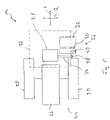
- the Figures 2 to 5 show the relative positioning of various system areas on the rear carriage 14 in relation to a machine longitudinal direction L and a machine transverse direction Q Fig.5 for example, the internal combustion engine 26 of the drive system 24, which is arranged essentially in a central area in the machine transverse direction Q.
- the internal combustion engine 26 supplies the energy required for the operation of the soil cultivation machine 10. This can either be stored using a generator arrangement in an energy store, from which motors to be operated electrically, for example for the travel drive, an unbalance drive or the like, are then fed.
- a hydraulic system can also be operated by the internal combustion engine 26 in order to feed hydraulic motors, for example for the traction drive or for operating various units of the soil treatment machine 10 .
- the drive wheels 20 are located on both sides of the internal combustion engine 26 arranged in a central area in the machine transverse direction Q.
- the driver's cab 22 is illustrated with a dashed line, which is offset in the machine longitudinal direction L with respect to the internal combustion engine 26, but can at least partially overlap with it.
- driver's cab 22 is essentially in front of internal combustion engine 26 or between internal combustion engine 26 and soil tillage roller 16.
- a fuel tank 28 for the fuel for example diesel fuel, which is to be supplied to the internal combustion engine 26 .
- the internal combustion engine 26 and the fuel tank 28 are thus located in the machine longitudinal direction L consecutively.
- the fuel tank 28 is positioned substantially centrally and below the operator's cab 22 .
- an additive tank 30 is arranged in the machine-length direction L to the in figure 5 drive wheel 20 positioned below and on the right in relation to a normal forward direction of travel. This is offset outwards in the cross-machine direction Q with respect to a central region and thus overlaps in the cross-machine direction Q with the drive wheel 20 positioned next to the additive tank 30.
- the additive tank 30 is arranged directly after the drive wheel 20. There is no other tank between these.
- the positioning of the additive tank 30 with respect to the fuel tank 28 is such that in the cross-machine direction Q the additive tank 30 follows the fuel tank 28, starting from the central region, and in the machine longitudinal direction L the additive tank 30 overlaps with the fuel tank 28, essentially arranged next to it is.
- a hydraulic fluid tank 32 is provided in the longitudinal machine direction L following the additive tank. This lies essentially next to the additive tank 30 in the machine transverse direction Q and essentially overlaps with it, so that the additive tank 30 lies in the machine longitudinal direction L essentially between the drive wheel 20 and the hydraulic fluid tank 32 .
- a fuel filler neck 34 of the fuel tank 28 is positioned such that it extends from the fuel tank 28, which is positioned substantially centrally in the cross-machine direction Q, to that side 36 of the rear structure 14 on which the additive tank 30 and the hydraulic fluid tank 32 are also positioned.
- the fuel filler neck 34 is thus located essentially between the additive tank 30 and the drive wheel 20 and, like the 2 This makes it clear that in the longitudinal direction L of the machine, areas overlap with the drive wheel 20 .
- a fuel filler opening 38 provided on this fuel filler neck 34 is positioned substantially adjacent to or close to an additive filler opening 40 of the additive tank 30 in the cross-machine direction Q.
- the fuel filler opening 38 and the additive filler opening 40 are therefore on the same side 36 of the rear vehicle 14 and are easily accessible for filling in the respective liquid substances.
- a filling opening of the hydraulic fluid tank 32 can also be arranged on this side 36 and in the machine longitudinal direction L following the other filling openings.
- the Figures 2 to 5 further show that not only is the centrally positioned fuel tank 28 substantially below the driver's cab 22, but that the driver's cab 22 in the longitudinal machine direction L and also the transverse machine direction Q essentially overlaps the additive tank 30 and also the hydraulic fluid tank 32.
- the driver's cab 22 and also the drive wheel 20 protect the additive tank 30 and the hydraulic fluid tank 32 against impact from above or from behind.
- a cover (not shown in the figures) can also be provided, which covers the additive tank 30, and possibly also the hydraulic fluid tank 32, in a box-like manner covered and can have a recess, for example in the area of the respective filling openings, or can be partially or completely removable.
- the relative positioning of the various tanks in relation to the drive assembly 26, in relation to the driver's cab 22 and also in relation to one of the drive wheels 20, as shown in the figures, makes it easy to access the various tanks for filling, if necessary also for checking the fill levels, with a compact design and efficient use of installation space , guaranteed.
- a protective effect is provided by surrounding in particular the additive tank 30 and the hydraulic fluid tank 32 with other system components of the rear vehicle.
- the additive tank 30 is located, partly also shielded by the fuel tank 28 and the drive wheel 20, comparatively close to the internal combustion engine 26, but is thermally well shielded from it. This also enables a comparatively short flow path for the additive between the additive tank 30 and an exhaust gas line system leading from the internal combustion engine 26 to the outside, for example in an area behind the driver's cab 22 .
Landscapes
- Engineering & Computer Science (AREA)
- Structural Engineering (AREA)
- Life Sciences & Earth Sciences (AREA)
- Civil Engineering (AREA)
- General Engineering & Computer Science (AREA)
- Mining & Mineral Resources (AREA)
- Mechanical Engineering (AREA)
- Chemical & Material Sciences (AREA)
- Transportation (AREA)
- Combustion & Propulsion (AREA)
- Environmental & Geological Engineering (AREA)
- Agronomy & Crop Science (AREA)
- Soil Sciences (AREA)
- General Life Sciences & Earth Sciences (AREA)
- Paleontology (AREA)
- Architecture (AREA)
- Sustainable Energy (AREA)
- Sustainable Development (AREA)
- Optics & Photonics (AREA)
- Physics & Mathematics (AREA)
- Cooling, Air Intake And Gas Exhaust, And Fuel Tank Arrangements In Propulsion Units (AREA)
- Road Paving Machines (AREA)
- Fertilizing (AREA)
Description
- Die vorliegende Erfindung betrifft eine Bodenbearbeitungsmaschine, insbesondere einen Bodenverdichter, der zur Durchführung von Bodenbearbeitungsvorgängen, wie z.B. zum Verdichten von Asphaltmaterial, Schottermaterial oder Erdreich eingesetzt werden kann.
- Ein derartiger Bodenverdichter ist im Allgemeinen mit einem Hinterwagen aufgebaut, an dem beidseits einer Brennkraftmaschine jeweils wenigstens ein Antriebsrad vorgesehen ist. An einem bezüglich des Hinterwagens schwenkbaren Vorderwagen ist eine Bodenbearbeitungswalze, beispielsweise Verdichterwalze, um eine Walzen-drehachse drehbar, welche sich im Wesentlichen in einer Maschinenquerrichtung erstreckt.
- Um die immer strenger werdenden Anforderungen hinsichtlich des Schadstoffausstoßes erfüllen zu können, wird bei derartigen Maschinen den aus der Brennkraftmaschine derselben, im Allgemeinen einem Dieselaggregat, ausgestoßenen Abgasen ein Zusatzstoff beigemengt, beispielsweise Harnstoff. In einer im Abgasströmungsweg vorgesehenen Katalysatoranordnung können dann unter Umsetzung des Zusatzstoffes chemische Reaktionen ablaufen, welche zu einem verminderten Stickoxidausstoß führen.
- Aus der
EP 2 754 870 A1 ist eine kettengetriebene Baumaschine bekannt, welche eine Diesel-Brennkraftmaschine als Antriebsaggregat aufweist. Im Bereich dieser Brennkraftmaschine ist ein Zusatzstofftank angeordnet. Um diesen nahe der Brennkraftmaschine positionierten Zusatzstofftank bzw. den darin enthaltenen Zusatzstoff vor Überhitzung und einer dadurch induzierten Zersetzung zu schützen, können verschiedene Maßnahmen zur Kühlung bzw. zum Vermeiden einer übermäßigen Erwärmung des Zusatzstoffs ergriffen werden. Beispielsweise kann der Zusatzstofftank in ein Isoliergehäuse eingebettet werden. Auch die Umströmung des Zusatzstofftanks mit Kühlmedium ist möglich. - Die gattungsgemässe
US 2014/0290224 A1 offenbart eine als Radlader ausgebildete Bodenbearbeitungsmaschine gemäß dem Oberbegriff des Anspruchs 1. Bei dieser bekannten Bodenbearbeitungsmaschine ist ein Zusatzstofftank in der Maschinenlängsrichtung unmittelbar folgend auf ein Hinterrad der Bodenbearbeitungsmaschine und in der Maschinenquerrichtung im Wesentlichen neben diesem Hinterrad angeordnet. Eine Einfüllöffnung des Zusatzstoffstanks liegt an derjenigen Seite der Bodenbearbeitungsmaschine, an welcher auch dieses Hinterrad vorgesehen. - Die
EP 2 431 536 A1 offenbart eine als Bagger ausgebildete Bodenbearbeitungsmaschine. Auf einem mit Kettenfahrwerken ausgebildeten Unterwagen ist ein einen Baggerarm, ein Antriebsaggregat und eine Führerkabine tragender Oberwagen um eine im Wesentlichen horizontale Achse drehbar getragen an einem Seitenrandbereich des Oberwagens ist ein Zusatzstofftank mit einer nach oben frei liegenden Einfüllöffnung angeordnet. - Es ist die Aufgabe der vorliegenden Erfindung, eine Bodenbearbeitungsmaschine, insbesondere einen Bodenverdichter, vorzusehen, welche bei optimierter Bauraumausnutzung eine eine übermäßige Erwärmung vermeidende Positionierung eines Zusatzstofftanks ermöglicht.
- Erfindungsgemäß wird diese Aufgabe gelöst durch eine Bodenbearbeitungsmaschine, insbesondere Bodenverdichter, gemäss den Merkmalen des Anspruchs 1 umfassend:
- einen Hinterwagen mit einer Brennkraftmaschine,
- beidseits der Brennkraftmaschine jeweils wenigstens eine Antriebsrad,
- eine in einer Maschinenlängsrichtung bezüglich der Brennkraftmaschine versetzt angeordnete Fahrerkabine,
- einen Kraftstofftank für der Brennkraftmaschine zuzuführenden Kraftstoff,
- einen Zusatzstofftank,
- einen Hydraulikflüssigkeitstank.
- Bei einer derart aufgebauten Bodenbearbeitungsmaschine ist erfindungsgemäß weiter vorgesehen, dass der Zusatzstofftank in der Maschinenlängsrichtung auf ein Antriebsrad folgend und in einer Maschinenquerrichtung im Wesentlichen neben dem Antriebsrad angeordnet ist.
- Bei derartiger Positionierung des Zusatzstofftanks ist dieser vergleichsweise weit weg von der Brennkraftmaschine positioniert und zumindest bereichsweise durch das Antriebsrad bezüglich der Brennkraftmaschine gegen Wärmeübertrag geschützt. Ferner liegt der Zusatzstofftank bei derartiger Positionierung in einem Bereich, der im Wesentlichen seitlich am Hinterwagen ist und somit insbesondere zum Befüllen des Zusatzstofftanks leicht zugänglich ist.
- Erfindungsgemäß ist eine Positionierung vorgesehen, bei welcher eine Einfüllöffnung des Zusatzstofftanks und eine Einfüllöffnung des Kraftstofftanks und eine Einfüllöffnung des Hydraulikflüssigkeitstanks an der selben Seite des Hinterwagens angeordnet sind. Somit sind die Einfüllöffnungen des Kraftstofftanks und des Zusatzstofftanks an der gleichen Seite des Hinterwagens gut zugänglich.
- Dabei kann beispielsweise vorgesehen sein, dass der Zusatzstofftank in der Maschinenlängsrichtung unmittelbar auf das Antriebsrad folgend angeordnet ist. Somit wird eine kompakte Bauart erhalten, bei welcher jedoch nicht ausgeschlossen ist, dass ein das Antriebsrad abdeckendes Schutzblech oder dgl. zwischen dem Antriebsrad und dem Zusatzstofftank liegt. Es liegt in diesem Bereich jedoch erfindungsgemäß kein weiterer Tank
- Da erfindungsgemäß der Zusatzstofftank in der Maschinenlängsrichtung zwischen dem Antriebsrad und dem Hydraulikflüssigkeitstank angeordnet ist, wird eine kompakte Bauart bei ebenfalls leichter Zugänglichkeit des Hydraulikflüssigkeitstanks zum Nachfüllen von Hydraulikflüssigkeit ermöglicht.
- Der Zusatzstofftank und der Hydraulikflüssigkeitstank können dabei in der Maschinenquerrichtung im Wesentlichen nebeneinanderliegend angeordnet sein, was die leichte Zugänglichkeit dieser beiden Tanks an der gleichen Seite des Hinterwagens ermöglicht.
- Eine effiziente Bauraumausnutzung kann bei einer Weiterbildung der Bodenbearbeitungsmaschine dadurch erreicht werden, dass der Zusatzstofftank oder/und der Hydraulikflüssigkeitstank wenigstens bereichsweise unter der Fahrerkabine angeordnet ist.
- Der Kraftstofftank kann in der Maschinenlängsrichtung auf die Brennkraftmaschine folgend und in der Maschinenquerrichtung in einem zentralen Bereich des Hinterwagens angeordnet sein. Dabei können der Zusatzstofftank und der Kraftstofftank sich in der Maschinenlängsrichtung wenigstens teilweise überlappend angeordnet sein.
- Insbesondere bei derartiger nahe beieinander liegender Positionierung des Zusatzstofftanks und des Kraftstofftanks kann weiter vorgesehen sein, dass ein Kraftstoffeinfüllstutzen des Kraftstofftanks sich wenigstens bereichsweise zwischen dem Zusatzstofftank und dem Antriebsrad erstreckt. Infolge dessen kann eine Positionierung erreicht werden, bei welcher eine Einfüllöffnung des Zusatzstofftanks und eine Einfüllöffnung des Kraftstofftanks oder/und eine Einfüllöffnung des Hydraulikflüssigkeitstanks in der Maschinenlängsrichtung im Wesentlichen aufeinander folgend angeordnet sind.
- Insbesondere beim Aufbau der Bodenbearbeitungsmaschine als Bodenverdichter kann ein Vorderwagen mit dem Hinterwagen schwenkbar verbunden sein, wobei am Vorderwagen eine Bodenbearbeitungswalze um eine im Wesentlichen in der Maschinenquerrichtung sich erstreckende Walzendrehachse drehbar ist.
- Die vorliegende Erfindung wird nachfolgend mit Bezug auf die beiliegenden Figuren detailliert beschrieben. Es zeigt:
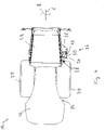
- Fig. 1
- eine Seitenansicht einer als Bodenverdichter ausgeführten Bodenbearbeitungsmaschine;
- Fig. 2
- eine Seitenansicht eines Hinterwagens;
- Fig. 3
- eine Frontansicht des Hinterwagens;
- Fig. 4
- eine Draufsicht auf den Hinterwagen;
- Fig. 5
- eine Prinzipdarstellung, welche die Relativlage verschiedener Systembereiche am Hinterwagen zeigt.
- Die als Bodenverdichter ausgeführte Bodenbearbeitungsmaschine 10 umfasst einen Vorderwagen 12 und einen mit diesem schwenkbar verbundenen Hinterwagen 14. Am Vorderwagen 12 ist eine Bodenbearbeitungswalze 16 zum Bearbeiten, beispielsweise Verdichten eines Bodens 18 um eine Walzendrehachse drehbar getragen. Am Hinterwagen 14 sind Antriebsräder 20 und eine Fahrerkabine 22 vorgesehen. Die Antriebsräder 20 sind beidseits einer nachfolgend noch beschriebenen Brennkraftmaschine eines Antriebssystems 24 angeordnet.
- Die
Fig. 2 bis 5 zeigen die Relativpositionierung verschiedener Systembereiche am Hinterwagen 14 bezogen auf eine Maschinenlängsrichtung L und eine Maschinenquerrichtung Q. So zeigt dieFig.5 beispielsweise die in der Maschinenquerrichtung Q im Wesentlichen in einem zentralen Bereich angeordnete Brennkraftmaschine 26 des Antriebssystems 24. Die Brennkraftmaschine 26 liefert die für den Betrieb der Bodenbearbeitungsmaschine 10 erforderliche Energie. Diese kann entweder unter Einsatz einer Generatoranordnung in einem Energiespeicher gespeichert werden, aus welchem dann elektrisch zu betreibende Motoren beispielsweise für den Fahrantrieb, einen Unwuchtantrieb oder dergleichen gespeist werden. Auch kann ein Hydrauliksystem durch die Brennkraftmaschine 26 betrieben werden, um Hydraulikmotoren, beispielsweise für den Fahrantrieb oder zum Betreiben verschiedener Aggregate der Bodenbearbeitungsmaschine 10, zu speisen. - In der Maschinenlängsrichtung L liegen beidseits der in einem zentralen Bereich in der Maschinenquerrichtung Q angeordneten Brennkraftmaschine 26 die Antriebsräder 20. In
Fig. 5 mit Strichlinie veranschaulicht ist die Fahrerkabine 22, die in der Maschinenlängsrichtung L bezüglich der Brennkraftmaschine 26 versetzt liegt, sich mit dieser aber zumindest teilweise überlappen kann. Bezogen auf eine im normalen Fahrbetrieb als Vorwärtsfahrtrichtung zu betrachtende Richtung, welche inFig. 1 eine Bewegungsrichtung nach links ist, liegt die Fahrerkabine 22 im Wesentlichen vor der Brennkraftmaschine 26 bzw. zwischen der Brennkraftmaschine 26 und der Bodenbearbeitungswalze 16. - Ebenfalls in einem zentralen Bereich in der Maschinenquerrichtung Q und in der Maschinenlängsrichtung L auf die Brennkraftmaschine 26 folgend liegt ein Kraftstofftank 28 für den Kraftstoff, also beispielsweise Dieselkraftstoff, welcher der Brennkraftmaschine 26 zuzuführen ist. Die Brennkraftmaschine 26 und der Kraftstofftank 28 liegen somit in der Maschinenlängsrichtung L aufeinander folgend. Der Kraftstofftank 28 ist im Wesentlichen zentral und unter der Fahrerkabine 22 positioniert.
- In der Maschinenlängsrichtung L auf das in
Fig. 5 unten und bezogen auf eine normale Vorwärtsfahrtrichtung rechts positionierte Antriebsrad 20 folgend ist ein Zusatzstofftank 30 angeordnet. Dieser liegt in der Maschinenquerrichtung Q bezüglich eines zentralen Bereichs nach außen versetzt und überlappt sich somit in der Maschinenquerrichtung Q mit dem neben dem Zusatzstofftank 30 positionierten Antriebsrad 20. Hier ist der Zusatzstofftank 30 unmittelbar auf das Antriebsrad 20 folgend angeordnet. Es liegt kein weiterer Tank zwischen diesen. Dabei ist die Positionierung des Zusatzstofftanks 30 bezüglich des Kraftstofftanks 28 so, dass in der Maschinenquerrichtung Q der Zusatzstofftank 30 ausgehend vom zentralen Bereich auf den Kraftstofftank 28 folgt und in der Maschinenlängsrichtung L der Zusatzstofftank 30 sich mit dem Kraftstofftank 28 überlappt, im Wesentlichen neben diesem angeordnet ist. - In der Maschinenlängsrichtung L auf den Zusatzstofftank folgend ist ein Hydraulikflüssigkeitstank 32 vorgesehen. Dieser liegt in der Maschinenquerrichtung Q im Wesentlichen neben dem Zusatzstofftank 30 und überlappt sich mit diesem im Wesentlichen, so dass der Zusatzstofftank 30 in der Maschinenlängsrichtung L im Wesentlichen zwischen dem Antriebsrad 20 und dem Hydraulikflüssigkeitstank 32 liegt.
- Ein Kraftstoffeinfüllstutzen 34 des Kraftstofftanks 28 ist so positioniert, dass er sich ausgehend von dem in der Maschinenquerrichtung Q im Wesentlichen zentral positionierten Kraftstofftank 28 zu derjenigen Seite 36 des Hinterwagens 14 erstreckt, an welcher auch der Zusatzstofftank 30 und der Hydraulikflüssigkeitstank 32 positioniert sind. Der Kraftstoffeinfüllstutzen 34 liegt somit im Wesentlichen zwischen dem Zusatzstofftank 30 und dem Antriebsrad 20 und kann, wie die
Fig. 2 dies verdeutlicht, in der Maschinenlängsrichtung L sich bereichsweise mit dem Antriebsrad 20 überlappen. Mit dieser Positionierung des Kraftstoffeinfüllstutzens 34 wird eine Anordnung geschaffen, bei welcher eine an diesem Kraftstoffeinfüllstutzen 34 vorgesehene Kraftstoffeinfüllöffnung 38 in der Maschinenquerrichtung Q im Wesentlichen neben einer Zusatzstoffeinfüllöffnung 40 des Zusatzstofftanks 30 bzw. nahe derselben positioniert ist. Die Kraftstoffeinfüllöffnung 38 und die Zusatzstoffeinfüllöffnung 40 liegen somit an der gleichen Seite 36 des Hinterwagens 14 und sind zum Einfüllen der jeweiligen flüssigen Stoffe gut zugänglich. Auch eine Einfüllöffnung des Hydraulikflüssigkeitstanks 32 kann an dieser Seite 36 und in der Maschinenlängsrichtung L auf die anderen Einfüllöffnungen folgend angeordnet sein. - Die
Fig. 2 bis 5 zeigen weiter, dass nicht nur der zentral positionierte Kraftstofftank 28 im Wesentlichen unter der Fahrerkabine 22 liegt, sondern dass die Fahrerkabine 22 in der Maschinenlängsrichtung L und auch der Maschinenquerrichtung Q den Zusatzstofftank 30 und auch den Hydraulikflüssigkeitstank 32 im Wesentlichen überlappt. Somit wird durch die Positionierung des Zusatzstofftanks 30 und des Hydraulikflüssigkeitstanks 32 in einem Bereich unter und sich überlappend mit der Fahrerkabine 22 der dort vorhandene Bauraum effizient genutzt. Gleichzeitig wird durch die Fahrerkabine 22 und auch das Antriebsrad 20 ein Schutz für den Zusatzstofftank 30 und den Hydraulikflüssigkeitstank 32 gegen Einwirkung von oben bzw. von hinten erreicht. Um diese Tanks, insbesondere den Zusatzstofftank, vor äußeren Einflüssen, beispielsweise auch vor übermäßiger Sonneneinstrahlung und damit übermäßiger Erwärmung schützen zu können, kann weiter eine in den Figuren nicht dargestellte Abdeckung vorgesehen sein, welche den Zusatzstofftank 30, ggf. auch den Hydraulikflüssigkeitstank 32, kastenartig überdeckt und beispielsweise im Bereich jeweiliger Einfüllöffnungen eine Aussparung aufweisen kann oder bereichsweise oder vollständig abnehmbar sein kann. - Durch die in den Figuren dargestellte Relativpositionierung der verschiedenen Tanks bezüglich des Antriebsaggregats 26, bezüglich der Fahrerkabine 22 und auch bezüglich eines der Antriebsräder 20 wird bei kompakter Ausgestaltung und effizienter Bauraumausnutzung einerseits eine leichte Zugänglichkeit der verschiedenen Tanks zum Befüllen, ggf. auch zum Überprüfen der Füllstände, gewährleistet. Gleichzeitig ist durch das Umgeben insbesondere des Zusatzstofftanks 30 und des Hydraulikflüssigkeitsktanks 32 mit anderen Systemkomponenten des Hinterwagens eines Schutzwirkung vorgesehen. Der Zusatzstofftank 30 liegt, teilweise auch abgeschirmt durch den Kraftstofftank 28 und das Antriebsrad 20, zwar vergleichsweise nahe an der Brennkraftmaschine 26, ist bezüglich dieser jedoch thermisch gut abgeschirmt. Dies ermöglicht auch einen vergleichsweise kurzen Strömungsweg für den Zusatzstoff zwischen dem Zusatzstofftank 30 und einem von der Brennkraftmaschine 26 beispielsweise in einem Bereich hinter der Fahrerkabine 22 nach außen führenden Abgasleitungssystem.
- Da die Einfüllöffnungen für den Kraftstofftank 28 und auch den Zusatzstofftank 30 in einem Bereich liegen, welche im Allgemeinen durch eine Abdeckhaube 42 für die Brennkraftmaschine 26 nicht überdeckt ist, ist es zum Befüllen dieser Tanks auch nicht erforderlich, diese Abdeckhaube 42 zu bewegen.
Claims (9)
- Bodenbearbeitungsmaschine, insbesondere Bodenverdichter, umfassend:- einen Hinterwagen (14) mit einer Brennkraftmaschine (26),- beidseits der Brennkraftmaschine (26) jeweils wenigstens ein Antriebsrad (20),- eine in einer Maschinenlängsrichtung (L) bezüglich der Brennkraftmaschine (26) versetzt angeordnete Fahrerkabine (22),- einen Kraftstofftank (28) für der Brennkraftmaschine (26) zuzuführenden Kraftstoff,- einen Zusatzstofftank (30),- einen Hydraulikflüssigkeitstank (32),wobei der Zusatzstofftank (30) in der Maschinenlängsrichtung (L) auf ein Antriebsrad (20) folgend und in einer Maschinenquerrichtung (Q) im Wesentlichen neben dem Antriebsrad (20) angeordnet ist,dadurch gekennzeichnet,dass der Zusatzstofftank (30) in der Maschinenlängsrichtung (L) zwischen dem Antriebsrad (20) und dem Hydraulikflüssigkeitstank (32) angeordnet ist, unddass eine Einfüllöffnung (40) des Zusatzstofftanks (30) und eine Einfüllöffnung (38) des Kraftstofftanks (28) und eine Einfüllöffnung des Hydraulikflüssigkeitstanks (32) an der selben Seite (36) des Hinterwagens (14) angeordnet sind.
- Bodenbearbeitungsmaschine nach Anspruch 1, dadurch gekennzeichnet, dass der Zusatzstofftank (30) in der Maschinenlängsrichtung (L) unmittelbar auf das Antriebsrad (20) folgend angeordnet ist.
- Bodenbearbeitungsmaschine nach Anspruch 1 oder 2, dadurch gekennzeichnet, dass der Zusatzstofftank (30) und der Hydraulikflüssigkeitstank in der Maschinenquerrichtung (Q) im Wesentlichen nebeneinander liegend angeordnet sind.
- Bodenbearbeitungsmaschine nach einem der Ansprüche 1 bis 3, dadurch gekennzeichnet, dass der Zusatzstofftank (30) oder/und der Hydraulikflüssigkeitstank (32) wenigstens bereichsweise unter der Fahrerkabine (22) angeordnet ist.
- Bodenbearbeitungsmaschine nach einem der Ansprüche 1 bis 4, dadurch gekennzeichnet, dass der Kraftstofftank (28) in der Maschinenlängsrichtung (L) auf die Brennkraftmaschine (26) folgend und in der Maschinenquerrichtung (Q) in einem zentralen Bereich des Hinterwagens (14) angeordnet ist.
- Bodenbearbeitungsmaschine nach einem der Ansprüche 1 bis 5, dadurch gekennzeichnet, dass der Zusatzstofftank (30) und der Kraftstofftank (28) sich in der Maschinenlängsrichtung (L) wenigstens teilweise überlappend angeordnet sind.
- Bodenbearbeitungsmaschine nach einem der Ansprüche 1 bis 5, dadurch gekennzeichnet, dass ein Kraftstoffeinfüllstutzen (34) des Kraftstofftanks (28) sich wenigstens bereichsweise zwischen dem Zusatzstofftank (30) und dem Antriebsrad (20) erstreckt.
- Bodenbearbeitungsmaschine nach einem der Ansprüche 1 bis 7, dadurch gekennzeichnet, dass eine Einfüllöffnung (40) des Zusatzstofftanks (30) und eine Einfüllöffnung (38) des Kraftstofftanks (28) oder/und eine Einfüllöffnung des Hydraulikflüssigkeitstanks (32) in der Maschinenlängsrichtung (L) im Wesentlichen aufeinanderfolgend angeordnet sind.
- Bodenbearbeitungsmaschine nach einem der Ansprüche 1 bis 8, dadurch gekennzeichnet, dass ein Vorderwagen (12) mit dem Hinterwagen (14) schwenkbar verbunden ist, wobei am Vorderwagen (12) eine Bodenbearbeitungswalze (16) um eine im Wesentlichen in Maschinenquerrichtung (Q) sich erstreckende Walzendrehachse drehbar ist.
Applications Claiming Priority (1)
| Application Number | Priority Date | Filing Date | Title |
|---|---|---|---|
| DE102014118995.7A DE102014118995A1 (de) | 2014-12-18 | 2014-12-18 | Bodenbearbeitungsmaschine, insbesondere Bodenverdichter |
Publications (3)
| Publication Number | Publication Date |
|---|---|
| EP3034347A1 EP3034347A1 (de) | 2016-06-22 |
| EP3034347B1 EP3034347B1 (de) | 2017-05-10 |
| EP3034347B2 true EP3034347B2 (de) | 2023-01-18 |
Family
ID=54936784
Family Applications (1)
| Application Number | Title | Priority Date | Filing Date |
|---|---|---|---|
| EP15199708.7A Active EP3034347B2 (de) | 2014-12-18 | 2015-12-14 | Bodenbearbeitungsmaschine, insbesondere bodenverdichter |
Country Status (3)
| Country | Link |
|---|---|
| US (1) | US10214087B2 (de) |
| EP (1) | EP3034347B2 (de) |
| DE (2) | DE102014118995A1 (de) |
Families Citing this family (9)
| Publication number | Priority date | Publication date | Assignee | Title |
|---|---|---|---|---|
| JP6615668B2 (ja) * | 2016-03-30 | 2019-12-04 | 住友建機株式会社 | アスファルトフィニッシャ |
| US10801179B2 (en) | 2017-12-15 | 2020-10-13 | Cnh Industrial America Llc | Hydraulic fluid storage tank including quick connect coupling |
| JP6708685B2 (ja) | 2018-03-23 | 2020-06-10 | 日立建機株式会社 | 作業車両のタンク |
| JP6752248B2 (ja) * | 2018-03-23 | 2020-09-09 | 日立建機株式会社 | 作業車両 |
| US11293155B2 (en) * | 2018-10-10 | 2022-04-05 | Maximum Density LLC | Landfill compactor |
| DE102019133272A1 (de) * | 2019-12-06 | 2021-06-10 | Hamm Ag | Tanksystem |
| CN112663423B (zh) * | 2020-12-17 | 2022-06-14 | 湖北交投建设集团有限公司 | 一种沥青路面高平整度施工方法 |
| US11891774B2 (en) * | 2021-03-26 | 2024-02-06 | Caterpillar Inc. | Structurally integrated fuel tank |
| DE102022113204A1 (de) * | 2022-05-25 | 2023-11-30 | Hamm Ag | Bodenbearbeitungswalze |
Citations (3)
| Publication number | Priority date | Publication date | Assignee | Title |
|---|---|---|---|---|
| EP1736350A2 (de) † | 2005-06-24 | 2006-12-27 | MAN Nutzfahrzeuge Aktiengesellschaft | Kraftfahrzeug mit einem Reduktionsmittelraum für eine Abgasreinigungsanlage |
| EP2479393A1 (de) † | 2009-09-17 | 2012-07-25 | Kobelco Construction Machinery Co. Ltd. | Baumaschine |
| DE102012112666B3 (de) † | 2012-12-19 | 2014-03-27 | Elkamet Kunststofftechnik Gmbh | Abdeckung mit Einfüllstutzen |
Family Cites Families (21)
| Publication number | Priority date | Publication date | Assignee | Title |
|---|---|---|---|---|
| CA2042890A1 (en) | 1991-05-17 | 1992-11-18 | Charles L. Poley | Soil compactor |
| DE29805539U1 (de) * | 1998-03-26 | 1998-06-18 | Vibromax Bodenverdichtungsmaschinen GmbH, 06466 Gatersleben | Bodenverdichtungsmaschine |
| JP2000192415A (ja) | 1998-12-24 | 2000-07-11 | Hitachi Constr Mach Co Ltd | ロードローラ |
| JP2002242121A (ja) | 2001-02-13 | 2002-08-28 | Sakai Heavy Ind Ltd | 転圧車両 |
| US7967099B2 (en) * | 2008-06-19 | 2011-06-28 | Caterpillar Paving Products Inc. | Method and arrangement of a plurality of propel pumps in a hydrostatically driven compactor |
| WO2011027765A1 (ja) * | 2009-09-02 | 2011-03-10 | 日立建機株式会社 | ホイール式作業車両 |
| JP5562777B2 (ja) * | 2010-09-16 | 2014-07-30 | 日立建機株式会社 | 建設機械 |
| JP5461453B2 (ja) | 2011-01-31 | 2014-04-02 | 日立建機株式会社 | 段差舗装用アタッチメント |
| DE102011005275A1 (de) * | 2011-03-09 | 2012-09-13 | Hamm Ag | Selbstfahrendes Baugerät, insbesondere Bodenverdichter |
| USD668269S1 (en) | 2011-04-28 | 2012-10-02 | Sakai Heavy Industries, Ltd. | Vibratory roller |
| DE102011085240A1 (de) | 2011-10-26 | 2013-05-02 | Hamm Ag | Selbstfahrender Bodenverdichter |
| US8695827B2 (en) | 2012-05-01 | 2014-04-15 | Deere & Company | Diesel exhaust fluid and fuel fill system |
| CA2779475C (en) * | 2012-05-29 | 2015-04-07 | Macdon Industries Ltd. | Windrower tractor with parallel heat exchangers for cooling of engine and associated fluids |
| JP5997507B2 (ja) | 2012-06-01 | 2016-09-28 | 日立建機株式会社 | 転圧機械 |
| JP2013249665A (ja) | 2012-06-01 | 2013-12-12 | Hitachi Constr Mach Co Ltd | 転圧機械 |
| JP5911392B2 (ja) * | 2012-07-20 | 2016-04-27 | 株式会社クボタ | 作業車 |
| PL2754870T3 (pl) * | 2013-01-11 | 2018-08-31 | Joseph Vögele AG | Układarka z układem zarządzania ciepłem |
| US9003779B2 (en) * | 2013-03-26 | 2015-04-14 | Komatsu Ltd. | Wheel loader |
| KR20200091944A (ko) * | 2013-04-26 | 2020-07-31 | 얀마 파워 테크놀로지 가부시키가이샤 | 작업 차량 |
| US20150022334A1 (en) * | 2013-07-19 | 2015-01-22 | Deere & Company | Progressive alert system for vehicle reservoir fluid fill level |
| JP2016098731A (ja) * | 2014-11-21 | 2016-05-30 | キャタピラー エス エー アール エル | 機体および作業機械 |
-
2014
- 2014-12-18 DE DE102014118995.7A patent/DE102014118995A1/de active Pending
- 2014-12-18 DE DE202014010518.9U patent/DE202014010518U1/de not_active Withdrawn - After Issue
-
2015
- 2015-12-14 EP EP15199708.7A patent/EP3034347B2/de active Active
- 2015-12-16 US US14/971,078 patent/US10214087B2/en active Active
Patent Citations (3)
| Publication number | Priority date | Publication date | Assignee | Title |
|---|---|---|---|---|
| EP1736350A2 (de) † | 2005-06-24 | 2006-12-27 | MAN Nutzfahrzeuge Aktiengesellschaft | Kraftfahrzeug mit einem Reduktionsmittelraum für eine Abgasreinigungsanlage |
| EP2479393A1 (de) † | 2009-09-17 | 2012-07-25 | Kobelco Construction Machinery Co. Ltd. | Baumaschine |
| DE102012112666B3 (de) † | 2012-12-19 | 2014-03-27 | Elkamet Kunststofftechnik Gmbh | Abdeckung mit Einfüllstutzen |
Non-Patent Citations (3)
| Title |
|---|
| Eidesstattliche Versicherung von Herrn Matthias Wolfram † |
| Gebrauchtmaschinenanzeige Walzenzug Hamm 3412, Baujahr 2013, auf machinerypark.com † |
| Wartungsanleitung Walzenzug Hamm 3412 P/HT/HT P † |
Also Published As
| Publication number | Publication date |
|---|---|
| US10214087B2 (en) | 2019-02-26 |
| US20160176278A1 (en) | 2016-06-23 |
| DE202014010518U1 (de) | 2015-11-09 |
| EP3034347B1 (de) | 2017-05-10 |
| DE102014118995A1 (de) | 2016-06-23 |
| EP3034347A1 (de) | 2016-06-22 |
Similar Documents
| Publication | Publication Date | Title |
|---|---|---|
| EP3034347B2 (de) | Bodenbearbeitungsmaschine, insbesondere bodenverdichter | |
| DE112013000147B4 (de) | Arbeitsfahrzeug | |
| EP2876209B1 (de) | Selbstfahrende Baumaschine | |
| DE112012000007B4 (de) | Baumaschine | |
| DE112013000191B4 (de) | Reduktionsmittelbehälter und Arbeitsfahrzeug | |
| DE112015000106T5 (de) | Hydraulikbagger | |
| DE112013000286T5 (de) | Motoreinheit und Baufahrzeug | |
| DE112012000301B4 (de) | Hydraulikbagger | |
| EP2241681A1 (de) | Bagger | |
| DE112012000378B4 (de) | Hydraulikbagger | |
| DE112015000922B4 (de) | Arbeitsfahrzeug | |
| DE202014010215U1 (de) | Kantenschneidsystem für einen Verdichter | |
| DE9308802U1 (de) | Straßenfertiger | |
| EP3945158B1 (de) | Schemelgelenkte tandemwalze und verfahren zum betrieb derartiger walzen | |
| DE112014000051B3 (de) | Arbeitsfahrzeug | |
| DE112013000260T5 (de) | Arbeitsfahrzeug | |
| DE2602898A1 (de) | Universal-arbeitsmaschine | |
| DE112015000025B4 (de) | Hydraulikbagger | |
| DE4213406C2 (de) | Baumaschine | |
| DE112015000230B4 (de) | Baumaschine | |
| DE112015001202B4 (de) | Arbeitsfahrzeug | |
| DE19839783B4 (de) | Steuerventilmechanismus für ein Arbeitsfahrzeug mit drehbarem Aufbau | |
| DE102016105888B4 (de) | Abgasnachbehandlungsanordnung, Motoranordnung und Arbeitsfahrzeug | |
| DE3827523A1 (de) | Stein-verlegemaschine | |
| DE102024118226A1 (de) | Mobile Arbeitsmaschine |
Legal Events
| Date | Code | Title | Description |
|---|---|---|---|
| PUAI | Public reference made under article 153(3) epc to a published international application that has entered the european phase |
Free format text: ORIGINAL CODE: 0009012 |
|
| 17P | Request for examination filed |
Effective date: 20151214 |
|
| AK | Designated contracting states |
Kind code of ref document: A1 Designated state(s): AL AT BE BG CH CY CZ DE DK EE ES FI FR GB GR HR HU IE IS IT LI LT LU LV MC MK MT NL NO PL PT RO RS SE SI SK SM TR |
|
| AX | Request for extension of the european patent |
Extension state: BA ME |
|
| GRAP | Despatch of communication of intention to grant a patent |
Free format text: ORIGINAL CODE: EPIDOSNIGR1 |
|
| RIC1 | Information provided on ipc code assigned before grant |
Ipc: E01C 19/28 20060101ALI20160929BHEP Ipc: B60K 15/063 20060101AFI20160929BHEP Ipc: E02F 9/08 20060101ALI20160929BHEP Ipc: E02D 3/026 20060101ALI20160929BHEP |
|
| INTG | Intention to grant announced |
Effective date: 20161027 |
|
| GRAJ | Information related to disapproval of communication of intention to grant by the applicant or resumption of examination proceedings by the epo deleted |
Free format text: ORIGINAL CODE: EPIDOSDIGR1 |
|
| STAA | Information on the status of an ep patent application or granted ep patent |
Free format text: STATUS: REQUEST FOR EXAMINATION WAS MADE |
|
| INTC | Intention to grant announced (deleted) | ||
| GRAS | Grant fee paid |
Free format text: ORIGINAL CODE: EPIDOSNIGR3 |
|
| STAA | Information on the status of an ep patent application or granted ep patent |
Free format text: STATUS: GRANT OF PATENT IS INTENDED |
|
| GRAP | Despatch of communication of intention to grant a patent |
Free format text: ORIGINAL CODE: EPIDOSNIGR1 |
|
| GRAA | (expected) grant |
Free format text: ORIGINAL CODE: 0009210 |
|
| STAA | Information on the status of an ep patent application or granted ep patent |
Free format text: STATUS: THE PATENT HAS BEEN GRANTED |
|
| INTG | Intention to grant announced |
Effective date: 20170316 |
|
| AK | Designated contracting states |
Kind code of ref document: B1 Designated state(s): AL AT BE BG CH CY CZ DE DK EE ES FI FR GB GR HR HU IE IS IT LI LT LU LV MC MK MT NL NO PL PT RO RS SE SI SK SM TR |
|
| REG | Reference to a national code |
Ref country code: GB Ref legal event code: FG4D Free format text: NOT ENGLISH |
|
| REG | Reference to a national code |
Ref country code: AT Ref legal event code: REF Ref document number: 891919 Country of ref document: AT Kind code of ref document: T Effective date: 20170515 Ref country code: CH Ref legal event code: EP |
|
| REG | Reference to a national code |
Ref country code: IE Ref legal event code: FG4D Free format text: LANGUAGE OF EP DOCUMENT: GERMAN |
|
| REG | Reference to a national code |
Ref country code: DE Ref legal event code: R096 Ref document number: 502015001036 Country of ref document: DE |
|
| REG | Reference to a national code |
Ref country code: SE Ref legal event code: TRGR |
|
| REG | Reference to a national code |
Ref country code: NL Ref legal event code: MP Effective date: 20170510 |
|
| REG | Reference to a national code |
Ref country code: LT Ref legal event code: MG4D |
|
| PG25 | Lapsed in a contracting state [announced via postgrant information from national office to epo] |
Ref country code: HR Free format text: LAPSE BECAUSE OF FAILURE TO SUBMIT A TRANSLATION OF THE DESCRIPTION OR TO PAY THE FEE WITHIN THE PRESCRIBED TIME-LIMIT Effective date: 20170510 Ref country code: GR Free format text: LAPSE BECAUSE OF FAILURE TO SUBMIT A TRANSLATION OF THE DESCRIPTION OR TO PAY THE FEE WITHIN THE PRESCRIBED TIME-LIMIT Effective date: 20170811 Ref country code: NO Free format text: LAPSE BECAUSE OF FAILURE TO SUBMIT A TRANSLATION OF THE DESCRIPTION OR TO PAY THE FEE WITHIN THE PRESCRIBED TIME-LIMIT Effective date: 20170810 Ref country code: LT Free format text: LAPSE BECAUSE OF FAILURE TO SUBMIT A TRANSLATION OF THE DESCRIPTION OR TO PAY THE FEE WITHIN THE PRESCRIBED TIME-LIMIT Effective date: 20170510 Ref country code: ES Free format text: LAPSE BECAUSE OF FAILURE TO SUBMIT A TRANSLATION OF THE DESCRIPTION OR TO PAY THE FEE WITHIN THE PRESCRIBED TIME-LIMIT Effective date: 20170510 Ref country code: FI Free format text: LAPSE BECAUSE OF FAILURE TO SUBMIT A TRANSLATION OF THE DESCRIPTION OR TO PAY THE FEE WITHIN THE PRESCRIBED TIME-LIMIT Effective date: 20170510 |
|
| PG25 | Lapsed in a contracting state [announced via postgrant information from national office to epo] |
Ref country code: IS Free format text: LAPSE BECAUSE OF FAILURE TO SUBMIT A TRANSLATION OF THE DESCRIPTION OR TO PAY THE FEE WITHIN THE PRESCRIBED TIME-LIMIT Effective date: 20170910 Ref country code: PL Free format text: LAPSE BECAUSE OF FAILURE TO SUBMIT A TRANSLATION OF THE DESCRIPTION OR TO PAY THE FEE WITHIN THE PRESCRIBED TIME-LIMIT Effective date: 20170510 Ref country code: BG Free format text: LAPSE BECAUSE OF FAILURE TO SUBMIT A TRANSLATION OF THE DESCRIPTION OR TO PAY THE FEE WITHIN THE PRESCRIBED TIME-LIMIT Effective date: 20170810 Ref country code: RS Free format text: LAPSE BECAUSE OF FAILURE TO SUBMIT A TRANSLATION OF THE DESCRIPTION OR TO PAY THE FEE WITHIN THE PRESCRIBED TIME-LIMIT Effective date: 20170510 Ref country code: NL Free format text: LAPSE BECAUSE OF FAILURE TO SUBMIT A TRANSLATION OF THE DESCRIPTION OR TO PAY THE FEE WITHIN THE PRESCRIBED TIME-LIMIT Effective date: 20170510 Ref country code: LV Free format text: LAPSE BECAUSE OF FAILURE TO SUBMIT A TRANSLATION OF THE DESCRIPTION OR TO PAY THE FEE WITHIN THE PRESCRIBED TIME-LIMIT Effective date: 20170510 |
|
| PG25 | Lapsed in a contracting state [announced via postgrant information from national office to epo] |
Ref country code: EE Free format text: LAPSE BECAUSE OF FAILURE TO SUBMIT A TRANSLATION OF THE DESCRIPTION OR TO PAY THE FEE WITHIN THE PRESCRIBED TIME-LIMIT Effective date: 20170510 Ref country code: DK Free format text: LAPSE BECAUSE OF FAILURE TO SUBMIT A TRANSLATION OF THE DESCRIPTION OR TO PAY THE FEE WITHIN THE PRESCRIBED TIME-LIMIT Effective date: 20170510 Ref country code: SK Free format text: LAPSE BECAUSE OF FAILURE TO SUBMIT A TRANSLATION OF THE DESCRIPTION OR TO PAY THE FEE WITHIN THE PRESCRIBED TIME-LIMIT Effective date: 20170510 Ref country code: RO Free format text: LAPSE BECAUSE OF FAILURE TO SUBMIT A TRANSLATION OF THE DESCRIPTION OR TO PAY THE FEE WITHIN THE PRESCRIBED TIME-LIMIT Effective date: 20170510 |
|
| REG | Reference to a national code |
Ref country code: DE Ref legal event code: R026 Ref document number: 502015001036 Country of ref document: DE |
|
| PLBI | Opposition filed |
Free format text: ORIGINAL CODE: 0009260 |
|
| PLAX | Notice of opposition and request to file observation + time limit sent |
Free format text: ORIGINAL CODE: EPIDOSNOBS2 |
|
| PG25 | Lapsed in a contracting state [announced via postgrant information from national office to epo] |
Ref country code: SM Free format text: LAPSE BECAUSE OF FAILURE TO SUBMIT A TRANSLATION OF THE DESCRIPTION OR TO PAY THE FEE WITHIN THE PRESCRIBED TIME-LIMIT Effective date: 20170510 Ref country code: IT Free format text: LAPSE BECAUSE OF FAILURE TO SUBMIT A TRANSLATION OF THE DESCRIPTION OR TO PAY THE FEE WITHIN THE PRESCRIBED TIME-LIMIT Effective date: 20170510 |
|
| 26 | Opposition filed |
Opponent name: BOMAG GMBH Effective date: 20180208 |
|
| PG25 | Lapsed in a contracting state [announced via postgrant information from national office to epo] |
Ref country code: SI Free format text: LAPSE BECAUSE OF FAILURE TO SUBMIT A TRANSLATION OF THE DESCRIPTION OR TO PAY THE FEE WITHIN THE PRESCRIBED TIME-LIMIT Effective date: 20170510 |
|
| PLBB | Reply of patent proprietor to notice(s) of opposition received |
Free format text: ORIGINAL CODE: EPIDOSNOBS3 |
|
| REG | Reference to a national code |
Ref country code: DE Ref legal event code: R082 Ref document number: 502015001036 Country of ref document: DE Representative=s name: RUTTENSPERGER LACHNIT TROSSIN GOMOLL PATENT- U, DE Ref country code: DE Ref legal event code: R082 Ref document number: 502015001036 Country of ref document: DE Representative=s name: RUTTENSPERGER LACHNIT TROSSIN GOMOLL, PATENT- , DE |
|
| REG | Reference to a national code |
Ref country code: IE Ref legal event code: MM4A |
|
| PG25 | Lapsed in a contracting state [announced via postgrant information from national office to epo] |
Ref country code: MT Free format text: LAPSE BECAUSE OF FAILURE TO SUBMIT A TRANSLATION OF THE DESCRIPTION OR TO PAY THE FEE WITHIN THE PRESCRIBED TIME-LIMIT Effective date: 20170510 Ref country code: LU Free format text: LAPSE BECAUSE OF NON-PAYMENT OF DUE FEES Effective date: 20171214 |
|
| REG | Reference to a national code |
Ref country code: FR Ref legal event code: ST Effective date: 20180831 |
|
| REG | Reference to a national code |
Ref country code: BE Ref legal event code: MM Effective date: 20171231 |
|
| PG25 | Lapsed in a contracting state [announced via postgrant information from national office to epo] |
Ref country code: FR Free format text: LAPSE BECAUSE OF NON-PAYMENT OF DUE FEES Effective date: 20180102 Ref country code: IE Free format text: LAPSE BECAUSE OF NON-PAYMENT OF DUE FEES Effective date: 20171214 |
|
| PG25 | Lapsed in a contracting state [announced via postgrant information from national office to epo] |
Ref country code: BE Free format text: LAPSE BECAUSE OF NON-PAYMENT OF DUE FEES Effective date: 20171231 |
|
| PG25 | Lapsed in a contracting state [announced via postgrant information from national office to epo] |
Ref country code: MC Free format text: LAPSE BECAUSE OF FAILURE TO SUBMIT A TRANSLATION OF THE DESCRIPTION OR TO PAY THE FEE WITHIN THE PRESCRIBED TIME-LIMIT Effective date: 20170510 Ref country code: HU Free format text: LAPSE BECAUSE OF FAILURE TO SUBMIT A TRANSLATION OF THE DESCRIPTION OR TO PAY THE FEE WITHIN THE PRESCRIBED TIME-LIMIT; INVALID AB INITIO Effective date: 20151214 |
|
| REG | Reference to a national code |
Ref country code: CH Ref legal event code: PL |
|
| PG25 | Lapsed in a contracting state [announced via postgrant information from national office to epo] |
Ref country code: CY Free format text: LAPSE BECAUSE OF FAILURE TO SUBMIT A TRANSLATION OF THE DESCRIPTION OR TO PAY THE FEE WITHIN THE PRESCRIBED TIME-LIMIT Effective date: 20170510 |
|
| PG25 | Lapsed in a contracting state [announced via postgrant information from national office to epo] |
Ref country code: MK Free format text: LAPSE BECAUSE OF FAILURE TO SUBMIT A TRANSLATION OF THE DESCRIPTION OR TO PAY THE FEE WITHIN THE PRESCRIBED TIME-LIMIT Effective date: 20170510 |
|
| PG25 | Lapsed in a contracting state [announced via postgrant information from national office to epo] |
Ref country code: CH Free format text: LAPSE BECAUSE OF NON-PAYMENT OF DUE FEES Effective date: 20181231 Ref country code: LI Free format text: LAPSE BECAUSE OF NON-PAYMENT OF DUE FEES Effective date: 20181231 |
|
| APBM | Appeal reference recorded |
Free format text: ORIGINAL CODE: EPIDOSNREFNO |
|
| APBP | Date of receipt of notice of appeal recorded |
Free format text: ORIGINAL CODE: EPIDOSNNOA2O |
|
| APAH | Appeal reference modified |
Free format text: ORIGINAL CODE: EPIDOSCREFNO |
|
| APBM | Appeal reference recorded |
Free format text: ORIGINAL CODE: EPIDOSNREFNO |
|
| APBP | Date of receipt of notice of appeal recorded |
Free format text: ORIGINAL CODE: EPIDOSNNOA2O |
|
| PG25 | Lapsed in a contracting state [announced via postgrant information from national office to epo] |
Ref country code: TR Free format text: LAPSE BECAUSE OF FAILURE TO SUBMIT A TRANSLATION OF THE DESCRIPTION OR TO PAY THE FEE WITHIN THE PRESCRIBED TIME-LIMIT Effective date: 20170510 |
|
| APBQ | Date of receipt of statement of grounds of appeal recorded |
Free format text: ORIGINAL CODE: EPIDOSNNOA3O |
|
| APBQ | Date of receipt of statement of grounds of appeal recorded |
Free format text: ORIGINAL CODE: EPIDOSNNOA3O |
|
| PG25 | Lapsed in a contracting state [announced via postgrant information from national office to epo] |
Ref country code: PT Free format text: LAPSE BECAUSE OF FAILURE TO SUBMIT A TRANSLATION OF THE DESCRIPTION OR TO PAY THE FEE WITHIN THE PRESCRIBED TIME-LIMIT Effective date: 20170510 |
|
| PG25 | Lapsed in a contracting state [announced via postgrant information from national office to epo] |
Ref country code: AL Free format text: LAPSE BECAUSE OF FAILURE TO SUBMIT A TRANSLATION OF THE DESCRIPTION OR TO PAY THE FEE WITHIN THE PRESCRIBED TIME-LIMIT Effective date: 20170510 |
|
| GBPC | Gb: european patent ceased through non-payment of renewal fee |
Effective date: 20191214 |
|
| PG25 | Lapsed in a contracting state [announced via postgrant information from national office to epo] |
Ref country code: GB Free format text: LAPSE BECAUSE OF NON-PAYMENT OF DUE FEES Effective date: 20191214 |
|
| REG | Reference to a national code |
Ref country code: AT Ref legal event code: MM01 Ref document number: 891919 Country of ref document: AT Kind code of ref document: T Effective date: 20201214 |
|
| PG25 | Lapsed in a contracting state [announced via postgrant information from national office to epo] |
Ref country code: AT Free format text: LAPSE BECAUSE OF NON-PAYMENT OF DUE FEES Effective date: 20201214 |
|
| APAN | Information on closure of appeal procedure modified |
Free format text: ORIGINAL CODE: EPIDOSCNOA9O |
|
| APBU | Appeal procedure closed |
Free format text: ORIGINAL CODE: EPIDOSNNOA9O |
|
| PUAH | Patent maintained in amended form |
Free format text: ORIGINAL CODE: 0009272 |
|
| STAA | Information on the status of an ep patent application or granted ep patent |
Free format text: STATUS: PATENT MAINTAINED AS AMENDED |
|
| 27A | Patent maintained in amended form |
Effective date: 20230118 |
|
| AK | Designated contracting states |
Kind code of ref document: B2 Designated state(s): AL AT BE BG CH CY CZ DE DK EE ES FI FR GB GR HR HU IE IS IT LI LT LU LV MC MK MT NL NO PL PT RO RS SE SI SK SM TR |
|
| REG | Reference to a national code |
Ref country code: DE Ref legal event code: R102 Ref document number: 502015001036 Country of ref document: DE |
|
| REG | Reference to a national code |
Ref country code: SE Ref legal event code: RPEO |
|
| PGFP | Annual fee paid to national office [announced via postgrant information from national office to epo] |
Ref country code: DE Payment date: 20251211 Year of fee payment: 11 |
|
| PGFP | Annual fee paid to national office [announced via postgrant information from national office to epo] |
Ref country code: SE Payment date: 20251219 Year of fee payment: 11 |
|
| PGFP | Annual fee paid to national office [announced via postgrant information from national office to epo] |
Ref country code: CZ Payment date: 20251210 Year of fee payment: 11 |