EP3029839B1 - Arithmetic logic device - Google Patents
Arithmetic logic device Download PDFInfo
- Publication number
- EP3029839B1 EP3029839B1 EP14831256.4A EP14831256A EP3029839B1 EP 3029839 B1 EP3029839 B1 EP 3029839B1 EP 14831256 A EP14831256 A EP 14831256A EP 3029839 B1 EP3029839 B1 EP 3029839B1
- Authority
- EP
- European Patent Office
- Prior art keywords
- bit
- output
- section
- memory device
- result
- Prior art date
- Legal status (The legal status is an assumption and is not a legal conclusion. Google has not performed a legal analysis and makes no representation as to the accuracy of the status listed.)
- Active
Links
Images


Classifications
-
- H—ELECTRICITY
- H03—ELECTRONIC CIRCUITRY
- H03K—PULSE TECHNIQUE
- H03K19/00—Logic circuits, i.e. having at least two inputs acting on one output; Inverting circuits
- H03K19/20—Logic circuits, i.e. having at least two inputs acting on one output; Inverting circuits characterised by logic function, e.g. AND, OR, NOR, NOT circuits
- H03K19/21—EXCLUSIVE-OR circuits, i.e. giving output if input signal exists at only one input; COINCIDENCE circuits, i.e. giving output only if all input signals are identical
-
- G—PHYSICS
- G06—COMPUTING; CALCULATING OR COUNTING
- G06F—ELECTRIC DIGITAL DATA PROCESSING
- G06F1/00—Details not covered by groups G06F3/00 - G06F13/00 and G06F21/00
- G06F1/02—Digital function generators
Definitions
- the present disclosure relates to a logic operation device that performs logical operations between bits included in input bit strings.
- Such error correction requires performing the exclusive-OR (XOR or EOR) operation between the bits that are inputted typically for parity check.
- Logic operation devices for performing the exclusive-OR operation on the data of long bit lengths have been formed traditionally by combining 2-input XOR circuits. For example, FIG. 11 shows a typical logic operation device that performs the exclusive-OR operation on 32-bit-long data.
- this logic operation device for performing the exclusive-OR operation on 32-bit-long data has four 8-input XOR circuits 100 and three 2-input XOR circuits 200. Each 8-input XOR circuit 100 has seven 2-input XOR circuits 200 inside.
- NPL 1 An example of the multiple-input (3-input) XOR gate is disclosed in NPL 1.
- US patent US 6 181 164 B1 also referred to as PL1 discloses a linear feedback shift register in a programmable gate array.
- a first lookup table is configured as a shift register having n selectable taps and a shift-input.
- a second lookup table is configured as a parity generator and has inputs coupled to the n selectable taps and an output coupled to the shift-input of the shift register.
- US patent application US 2003/0068038 A1 also referred to as PL2
- PL2 relates to a method and apparatus for encrypting data.
- look-up tables in the field programmable gate array are used to store preselected values for the substitution box used in many encryption/decryption schemes. Utilizing look-up tables in such a manner reduces the overall gate count in the FPGA device resulting in quicker speeds, lower power consumption, and the ability to reconfigure the device for different encryption/decryption implementations.
- An object of the disclosure is to provide a logic operation device that performs logic processing on multiple-bit data in a relatively short time on a relatively small circuit scale.
- a logic operation device comprising: a memory device configured to receive an input of a N-bit long bit string and to store a lookup table, N being an integer of at least 2, the lookup table storing multiple-bit long data in an address represented by the input bit string, and a bit representative of a result of a logical operation performed between the bits included in the input bit string being stored in a part of the multiple-bit long data; and an output means configured to access the memory device and outputs the bits included in the data stored at the address represented by the received bit string and an output means configured to access the memory device and outputs the bits included in the data stored at the address represented by the received bit string, characterized in that it further comprises:a time-shared extracting means configured to receive the input of a bit string M bits long, M being an integer larger than N, the time-shared extracting means extracting an N-bit string from the M-bit string to output the extracted N-bit string to the memory device on a time-
- the present disclosure achieves arithmetic processing in a relatively short time on a relatively small circuit scale.
- a logic operation device 1 includes at least one logic operation unit 10, as shown in FIG. 1 .
- the logic operation unit 10 is basically structured to include an input buffer section 11, a memory device 12, and an output section 13.
- the input buffer section 11 receives a bit string N bits long (N is an integer of at least 2) and supplies a signal represented by the bit string onto the address bus of the memory device 12. That is, the number N in this example also denotes the address bus width of the memory device 12.
- the memory device 12 is specifically a nonvolatile memory or a semiconductor memory such as a static random access memory (SRAM) having as many memory cells as 2N bits ⁇ L bits (L is an integer of at least 2).
- SRAM static random access memory
- the memory device 12 stores a lookup table in which multiple-bit data of which a part includes a bit representative of the result of a logical operation performed between the bits included in a bit string inputted through the input buffer section 11 is stored at an address represented by the inputted bit string.
- the output section 13 reads from the data in the memory device 12 the data stored at the address represented by the bit string outputted from the input buffer section 11.
- the output section 13 selectively outputs from the retrieved data the bit corresponding to the result of the above-mentioned logical operation.
- the MSB includes the result of the logical operation.
- the output section 13 thus reads from the data in the memory device the data stored at the address represented by the bit string outputted from the input buffer section 11, and outputs the MSB from the retrieved data.
- the memory device 12 stores a lookup table in which, at the address represented by the bit string input from the inputted buffer section 11, there is stored multiple-bit data of which one bit indicates the result of the logical operation performed between the bits included in the input bit string and of which another bit indicates the inverse of the logical operation result.
- the output section 13 receives the input of a 1-bit signal from the outside.
- the output section 13 reads from the data in the memory device 12 the data stored at the address represented by a bit string outputted from the input buffer section 11.
- the output section 13 selectively outputs from the retrieved data either the bit indicating the result of the logical operation or the bit indicating the inverse of the logical operation result.
- the output section 13 if the externally inputted 1-bit signal is "0,” the output section 13 reads from the data in the memory device the data stored at the address represented by the bit string outputted from the input buffer section 11, and outputs the MSB from the retrieved data.
- the output section 13 reads from the data in the memory device the data stored at the address represented by the bit string outputted from the input buffer section 11, and outputs the next MSB (the bit indicating the inverse of the logical operation result) from the retrieved data.
- the embodiment of the present disclosure is basically structured as described above, and operates as explained below in connection with following examples.
- One example includes multiple arithmetic logic units 10_1, 10_2, ⁇ , and 10_n.
- An output section 13_i of an i-th logic operation unit 10_i receives the bit output from an (i-1) -th logic operation unit 10_i-1 as input from the outside.
- the output section 13_1 of the first arithmetic logic unit 10_1 does not receive input from the outside (or, is assumed to receive a fixed "0, " for example, from the outside) ; the output section 13_1 outputs the bit indicating the result of the logical operation (MSB in the above example) from among the data stored in the memory device 12.
- the data D is outputted, in group of 8 bits (address bus width of the memory device 12) starting from the MSB (or the LSB), to the input buffer sections 11_1, 11_2, ⁇ , and 11_n of the arithmetic logic units 10_1, 10_2, ⁇ , and 10_n, respectively.
- the output section 13_1 of the logic operation unit 10_1 reads from the data in the memory device 12_1 the data stored at the address represented by 8-bit string (b1, b2, ⁇ , b8) inputted to the input buffer 11_1.
- the output section 13_1 then outputs the bit indicating the result of the logical operation (here, the bit represents the result of the exclusive-OR operation performed on the input 8-bit string) from the retrieved data .
- the output section 13_2 of the next arithmetic logic unit 10_2 reads from the data in the memory device 12_2 the data stored at the address represented by 8-bit string (b9, b10, ⁇ , b16) inputted to the input buffer 11_2.
- the output section 13_2 selectively outputs from the retrieved data either the bit indicating the result of the logical operation or the bit indicating the inverse of the logical operation result on the basis of the bit output from the output section 13_1 of the logic operation unit 10_1 of the immediately proceeding stage. Specifically, if the bit output from the output section 13_1 is "0,” the output section 13_2 outputs from the retrieved data the bit indicating the result of the logical operation. If the bit output from the output section 13_1 is "1," the output section 13_2 outputs the bit indicating the inverse of the logical operation result.
- the output section 13_i of the i-th logic operation unit 10_i reads from the data in the memory device 12_i the data stored at the address represented by 8-bit string (b8(i-1)+1, b8(i-1)+2, ⁇ , b8i) inputted to the input buffer 11_i.
- the output section 13_i selectively outputs from the retrieved data either the bit indicating the result of the logical operation or the bit indicating the inverse of the logical operation result on the basis of the bit output from the output section 13_i-1 of the upstream arithmetic logic unit 10_i-1.
- the output section 13_i-1 if the bit outputted from the output section 13_i-1 is "0, " the output section 13_i outputs the bit indicating the result of the logical operation from the retrieved data. If the bit output from the output section 13_i-1 is "1, " the output section 13_i outputs the bit indicating the inverse of the logical operation result from the retrieved data.
- the output section 13_n of the n-th logic operation unit 10_n reads from the data in the memory device 12_n the data stored at the address represented by 8-bit string (b8 (n-1) +1, b8 (n-1) +2, ⁇ , b8n) inputted to the input buffer 11_n.
- the output section 13_n selectively outputs from the retrieved data either the bit indicating the result of the logical operation or the bit indicating the inverse of the logical operation result on the basis of the bit outputted from the output section 13_n-1 of the upstream arithmetic logic unit 10_n-1.
- the output section 13_n outputs the bit indicating the result of the logical operation from the retrieved data. If the bit outputted from the output section 13_n-1 is "1, " the output section 13_n outputs the bit indicating the inverse of the logical operation result from the retrieved data .
- the output section 13_n of the n-th logic operation unit 10_n outputs the result of the logical operation (exclusive-OR operation in this example) performed on the bits included in the data D of 8 ⁇ n bits.
- a logic operation unit 1 according to the embodiment of the disclosure is structured to include, as shown in FIG. 5 , n three-state buffer sections 20, a memory device 12, a clock supply section 25, and an output unit 30.
- the output unit 30 includes an output section 31, a flip-flop circuit section 32, and a switch section 33.
- Each three-state buffer 21 has an input terminal X, an output terminal Y, and a gate terminal G. As long as the input to the gate terminal G remains "0,” the three-state buffer 21 holds the output terminal Y in a high-impedance state "Z" regardless of the input to the input terminal X.
- 8n three-state buffers 21 are divided into groups of eight, e.g., the first through the eighth three-state buffers 21_1 through 21_8 making up the first group, the ninth through the 16th three-state buffers 21-9 through 21_16 making up the second group, and so on.
- the gate terminals G of the three-state buffers 21 belonging to the same group are supplied with the same signal from the clock supply section 25. This signal will be discussed later in more detail.
- the bits in the data D that is 8xn bits long and subject to the logical operation are inputted successively starting from the MSB (or LSB) to the input terminal X_i of the i-th three-state buffer 21_i.
- the output terminal Y_i of the i-th three-state buffer 21_i is connected to the (i mod 8) -th pin on the address bus of the memory device 12.
- (i mod k) means the remainder left over when i is divided by k.
- the clock supply section 25 generates and outputs a clock signal CLK that rises and falls in a periodically repeated manner.
- the rising or falling timing of the sub clock signal ⁇ 1 is as follows .
- the sub clock signal cp0 is controlled to fall when the clock signal CLK rises immediately before the clock signal CLK falls for the (n/2+1)-th time, i.e., for the third time, after time t9.
- the clock supply section 25 supplies the sub clock signal ⁇ 1 to the first through the eighth three-state buffers 21_1 through 21_8, the sub clock signal ⁇ 2 to the ninth through the 16th three-state buffers 21_9 through 21_16, and so on, thus supplying the sub clock signal ⁇ ([(p-1)/8]+1) to each of the eight three-state buffers 21_p (p is an integer of at least 1).
- [*] means the largest integer not exceeding *.
- the three-state buffers 21 and the clock supply section 25 working as described above implement bit conversion or time-shared extracting means that receives the input of a bit string of M bits (M is an integer larger than N), extracts an N-bit string from the input M-bit string, and outputs the extracted N-bit string to the memory device 12 on a time-sharing basis.
- the output section 31 of the output unit 30 receives the input of a 1-bit signal from the flip-flop circuit section 32 and holds the received signal in a buffer (not shown) .
- the output section 31 reads from the data in the memory device 12 the data stored at the address represented by the bit string outputted from the three-state buffers 21.
- the output section 31 selectively outputs from the retrieved data either the bit indicating the result of the logical operation or the bit indicating the inverse of the logical operation result.
- the output section 31 if the bit held in the buffer is "0,” the output section 31 outputs the MSB (bit indicating the result of the logical operation) from the data read from the memory device 12 to the switch section 33. If the bit held in the buffer is "1,” the output section 31 outputs the next MSB (i.e., bit indicating the inverse of the logical operation result) from the data read from the memory device 12 to the switch action 33. The output section 31 continues the output until the clock signal CLK falls next time.
- the output section 31 further controls the switch section 33, as is discussed later. Specifically, at the time the sub clock signal ⁇ n (n is the number obtained by dividing the number of bits 8n subject to the logical operation by the address bus width 8 of the memory device 12) from the clock supply section 25 rises, the output section 31 sets the destination of the output from the switch section 33, to be explained later, to the outside. The next time the clock signal CLK from the clock supply section 25 rises, the output section 31 sets the the destination of the output from the switch section 33 to the flip-flop circuit section 32.
- the output section 31 holds the "0" bit in the buffer regardless of the output of the flip-flop circuit section 32. This operation is called the reset operation of the output section in the description that follows.
- the flip-flop circuit section 32 is structured to include, for example, a D-type flip-flop circuit. Specifically, a D terminal (input terminal) of the flip-flop circuit 24 receives the output from the output section 31. The C terminal (clock terminal) of the flip-flop circuit 24 receives the input of the clock signal CLK from the clock supply section 25. At the time the clock signal CLK rises, the flip-flop circuit section 32 holds the bit inputted to the D terminal (input terminal) and outputs a signal representative of that bit to an output terminal Q. This output is continued even when the clock signal CLK falls. The bit outputted from the output terminal Q is inputted to the output section 31 as the output from the flip-flop circuit section 32.
- the switch section 33 selectively outputs the 1-bit information from the output section 31 either to the flip-flop circuit section 32 or to the outside.
- the logic operation device 1 works as follows : With the reset operation performed (at time t0 in FIG. 6 ), the output section 31 holds the "0" bit in the buffer. The next time the clock signal CLK from the clock supply section 25 rises (at time t1 in FIG. 6 ), the three-state buffers 21_1 through 21_8 feed the input bits b1, b2, ⁇ , and b8 onto the address bus of the memory device 12.
- the output section 31 From the data in the memory device 12, the output section 31 reads the data stored at the address represented by the bit string outputted from the three-state buffers 21_1 through 21_8. At this moment, the buffer of the output section 31 holds the "0" bit, so that the output section 31 outputs from the data retrieved from the memory device 12 the MSB (bit indicating the result of the logical operation) as a first-time operation result R1.
- the output R1 is sent to the flip-flop circuit section 32 via the switch section 33 and is held in the flip-flop circuit section 32.
- the outputs from the three-state buffers 21_1 through 21_8 are in the high-impedance state.
- the output section 31 then receives the preceding operation result R1 from the flip-flop circuit 32 and holds it in the buffer.
- the three-state buffers 21_9 through 21_16 feed the input bits b9, b10, ⁇ , and b16 onto the address bus of the memory device 12.
- the output section 31 From the data in the memory device 12, the output section 31 reads the data stored at the address represented by the bit string composed of bits outputted from the three-state buffers 21_9 through 21_16. If the buffer holds a "0" bit (if the operation result R1 is “0"), the output section 31 outputs the MSB (bit indicating the result of the logical operation) as a second-time operation result R2, from among the data retrieved from the memory device 12. If the buffer holds a "1" bit (if the operation result R1 is "1”), the output section 31 outputs the next most significant bit (bit indicating the inverse of the logical operation result) as the second-time operation result R2, from among the data retrieved from the memory device 12. The output R2 is sent to the flip-flop circuit section 32 via the switch section 33 and is held in the flip-flop circuit section 32.
- the output section 31 sets the destination of the output from the switch section 33 to the outside. At this moment, the output section 31 reads the data stored at the address represented by the bit string composed of the bits outputted from three-state buffers 21_(8 ⁇ (n-1)+1) through 21_(8n) in the memory device 12. If the buffer holds the "0" bit (if the operation result Rn-1 is "0"), the output section 31 outputs the MSB (bit indicating the result of the logical operation) as the operation result R, from among the data retrieved from the memory device 12.
- the output section 31 If the buffer holds the "1" bit (if the operation result Rn-1 is "1"), the output section 31 outputs the next MSB (bit indicating the inverse of the logical operation result) as the operation result R, from among the data retrieved from the memory device 12. This output is fed to the outside via the switch section 33.
- the output section 31 performs the reset operation.
- the output section 31 sets the flip-flop circuit section 32 as the destination to which the output of the switch section 33 is directed.
- the output section 31 functions as the means to selectively output either the bit indicating the result of the logical operation performed between the bits retrieved by accessing the memory device using the previously outputted bits, or the bit indicating the inverse of the logical operation result.
- the output section 31 outputs as the operation result R the result of the logical operation (exclusive-OR operation in this example) performed on the bits included in the data D of 8 ⁇ n bits.
- An example of the output unit where the logical operation is performed on a time-sharing basis is not limited to that disclosed above. Since each address in the memory device 12 accommodates 8-bit data, there maybe provided alternatively another output device by making effective use of the 8-bit width, as explained below.
- the output unit 40 is structured to include four selector sections 41a, 41b, 41c, and 41d (number 4 represents half of the data bus width L of the memory device 12).
- combinations of the result of the logical operation based on the bit string a1, a2, ⁇ , and a8 with the bit indicating the inverse of the logical operation result are arranged repeatedly at locations each represented by an 8-bit address A (represented by the bit string a1, a2, ⁇ , and a8). That is, in this example, the result of the logical operation is stored in each odd-numbered bit position of the data stored at each address location, and the inverse of the logical operation result is stored in each even-numbered bit position of the data thus stored.
- the selector section 41a in the output unit 40 is connected with a signal line d1 representative of the MSB and with a signal line d2 representative of the next MSB, out of the signal lines making up the data bus of the memory device 12.
- the selector section 41a also receives an externally inputted 1-bit signal.
- the selector section 41a reads the data, stored at the address represented by the bit string output from the three-state buffers 21 from among the data in the memory device 12, and latches the retrieved data. Depending on whether the externally inputted 1-bit signal is "0" or "1, " the selector section 41a selectively latches from the retrieved data either the MSB (1 bit) indicating the result of the logical operation or the next MSB indicating the inverse of the logical operation result, and outputs the latched bit.
- the selector section 41a selectively latches the MSB (indicating the result of the logical operation, output through the signal line d1) from among the data retrieved from the memory device 12 and outputs the latched bit. If the externally inputted bit is "1,” the selector section 41a selectively latches the next MSB (outputted through the signal line d2, indicating the inverse of the logical operation result) from among the data retrieved from the memory device 12 and outputs the latched bit.
- the selector section 41b is connected with a signal line d3 nearer to the MSB and with a signal line d4 that is the next bit, the signal lines making up the data bus of the memory device 12.
- the selector section 41b also receives the 1-bit signal from the selector section 41a.
- the selector section 41b reads the data stored at the address represented by the bit string outputted from the three-state buffers 21 in the memory device 12, and latches the retrieved data. Depending on whether the 1-bit signal received from the selector section 41a is "0" or "1, " the selector section 41b selectively latches from the retrieved data either the MSB-side bit indicating the result of the logical operation or the next bit indicating the inverse of the logical operation result, and outputs the latched bit.
- the selector section 41b selectively latches the MSB-side bit (indicating the result of the logical operation, outputted through the signal line d3) from among the data retrieved from the memory device 12 and outputs the latched bit. If the bit received from the selector section 41a is "1, " the selector section 41b selectively latches from the data retrieved from the memory device 12 the bit through the signal line d4 next to the signal line d3 (the bit indicating the inverse of the logical operation result) and outputs the latched bit.
- the selector section 41c is connected with a signal line d5 nearer to the MSB and with a signal line d6 that is the next bit, out of the signal lines making up the data bus of the memory device 12.
- the selector section 41c also receives the 1-bit signal outputted from the selector section 41b.
- the selector section 41c reads the data stored at the address represented by the bit string outputted from the three-state buffers 21 in the memory device 12, and latches the retrieved data. If the bit received from the selector section 41b is "0,” the selector section 41c of this example selectively latches the MSB-side bit (indicating the result of the logical operation, output through the signal line d5) from among the data retrieved from the memory device 12, and outputs the latched bit.
- the selector section 41c selectively latches from the data retrieved from the memory device 12 the bit represented through the signal line d6 next to the signal line d5 (the bit indicating the inverse of the logical operation result), and outputs the latched bit.
- the selector section 41d is connected with a signal line d7 on the side of the MSB and with a signal line d8 that is the next bit, out of the signal lines making up the data bus of the memory device 12.
- the selector section 41d further receives the 1-bit signal from the selector section 41c.
- the selector section 41d reads the data stored at the address represented by the bit string outputted from the three-state buffers 21 in the memory device 12, and latches the retrieved data. If the bit received from the selector section 41c is "0, " the selector section 41d of this example selectively latches the MSB-side bit (indicating the result of the logical operation, outputted through the signal line d7) from among the data retrieved from the memory device 12, and outputs the latched bit.
- the selector section 41c selectively latches from among the data retrieved from the memory device 12 the bit represented through the signal line d8 next to the signal line d7 (the bit indicating the inverse of the logical operation result), and outputs the latched bit.
- the output of the selector section 41d is outputted to the outside.
- the i-th bit counted from the MSB (or LSB) is input successively to the i-th three-state buffer 21_i.
- the logic operation device 1 works as follows. After the output of the selector section 41d has been delivered(at time t0 in FIG. 6 ),and then when the next time the clock signal CLK and the sub clock signal ⁇ 1 from the clock supply section 25 rise (at time t1 in FIG. 6 ), the three-state buffers 21_1 through 21_8 feed the input bits b1, b2, ⁇ , and b8 onto the address bus of the memory device 12.
- the selector section 41a in the output unit 40 reads the data stored at the address represented by the bit string composed of the bits outputted respectively from the three-state buffers 21_1 through 21_8 in the memory device 12. It is assumed that a "0" signal is being inputted to the selector section 41a from the outside.
- the selector section 41a has a latch that latches the MSB (data outputted though the signal line d1 of the data bus, indicating the result of the logical operation) from among the data retrieved from the memory device 12 as an operation result R1, and outputs the latched result R1 at the time the sub clock signal ⁇ 1rises (at time t1 in FIG. 6 ).
- the output R1 is sent to the selector section 41b.
- the selector section 41b receives the output R1. Then when the clock signal CLK and the sub clock signal ⁇ 2 from the clock supply section 25 rise (at time t3 in FIG. 6 ), the three-state buffers 21_9 through 21_16 feed the input bits b9, b10, ⁇ , and b16 onto the address bus of the memory device 12.
- the selector section 41b reads the data stored at the address represented by the bit string composed of bits respectively outputted from the three-state buffers 21_9 through 21_16 in the memory device 12. If the bit received from the selector section 41a is "0" (i.e., if the operation result R1 is "0"), the selector section 41b latches the MSB-side bit (outputted through the signal line d3 of the data bus, indicating the result of the logical operation) as an operation result R2 at the time the sub clock signal ⁇ 2 rises (at time t3 in FIG. 6 ) from among the data retrieved from the memory device 12, and outputs the latched result R2.
- the selector section 41b latches from the data retrieved from the memory device 12 the bit outputted through the signal line d4 (i.e. the bit indicating the inverse of the logical operation result) as the operation result R2 at the time the sub clock signal ⁇ 2 rises (at time t3 in FIG. 6 ), and outputs the latched result R2.
- the output R2 is received by the selector section 41c.
- the subsequent selector sections 41c ⁇ operate in like manner.
- the three-state buffers 21_25 through 21_32 feed the inputted bits b25, b26, ⁇ , and b32 onto the address bus of the memory device 12.
- the selector section 41d latches the MSB-side bit (output though the signal line d7 of the data bus, indicating the result of the logical operation) of the data retrieved from the memory device 12 as the operation result R at the time the sub clock signal ⁇ 4 rises, and outputs the latched result R. If the bit input from the selector section 41c is "1" (if the operation result R3 is “1"), the selector section 41d latches from the data retrieved from the memory device 12 the output through the signal line d8 (i.e. the bit indicating the inverse of the logical operation result) as the operation result R at the time the sub clock signal ⁇ 4 rises, and outputs the latched result R.
- the signal line d8 i.e. the bit indicating the inverse of the logical operation result
- the output unit 40 of the embodiment functions as the means to selectively output either the bit indicating the result of the logical operation performed between the bits retrieved by accessing the memory device using the previously output bits, or the bit indicating the inverse of the logical operation result.
- the output section 31 or the output unit 40 is shown to switch between the output of either an odd-numbered bit or an even-numbered bit in the data retrieved from the memory device 12 using the output from the previous stage.
- this concept does not limit the scope of the present disclosure.
- an inverting (NOT) circuit 51 may be connected with a signal line d (on which is outputted the logical operation result using the bit string represented by the address input to the memory device 12) output from the memory device 12, so as to obtain the bit indicating the inverse of the logical operation result using the bit string represented by the address inputted to the memory device 12.
- the output section 31 or the output unit 40 selects either the output of the signal line d or that of the NOT circuit 51 (the output unit 40 latches the output) using the output from the previous stage, and outputs what is selected.
- the 1-bit output from each logic operation device 1 is input to the 8-input XOR circuit 100, the same as the one shown in FIG. 11 , whereby the exclusive-OR operation is performed on the bits to obtain one bit indicating the result of the exclusive-OR operation.
Description
- The present disclosure relates to a logic operation device that performs logical operations between bits included in input bit strings.
- Along with further advances and growth in information processing technology and information communication technology has come the need for processing more and more information faster than before. In recent years, for example, the process of error correction in information processing has been required to handle data of longer bit lengths than ever before.
- Such error correction requires performing the exclusive-OR (XOR or EOR) operation between the bits that are inputted typically for parity check. Logic operation devices for performing the exclusive-OR operation on the data of long bit lengths have been formed traditionally by combining 2-input XOR circuits. For example,
FIG. 11 shows a typical logic operation device that performs the exclusive-OR operation on 32-bit-long data. - As shown in
FIG. 11 , this logic operation device for performing the exclusive-OR operation on 32-bit-long data has four 8-input XOR circuits 100 and three 2-input XOR circuits 200. Each 8-input XOR circuit 100 has seven 2-input XOR circuits 200 inside. - An example of the multiple-input (3-input) XOR gate is disclosed in
NPL 1. - US patent
US 6 181 164 B1 , also referred to as PL1, discloses a linear feedback shift register in a programmable gate array. A first lookup table is configured as a shift register having n selectable taps and a shift-input. A second lookup table is configured as a parity generator and has inputs coupled to the n selectable taps and an output coupled to the shift-input of the shift register. - US patent application
US 2003/0068038 A1 , also referred to as PL2, relates to a method and apparatus for encrypting data. To improve data encryption and/or decryption, look-up tables in the field programmable gate array are used to store preselected values for the substitution box used in many encryption/decryption schemes. Utilizing look-up tables in such a manner reduces the overall gate count in the FPGA device resulting in quicker speeds, lower power consumption, and the ability to reconfigure the device for different encryption/decryption implementations. - [NPL 1]
inet: "74LVC1G386 3-input EXCLUSIVE-OR gate," [online], September 3, 2007, [searched on July 16, 2013], Internet <URL: http://www.jp.nxp.com/documents/data_sheet/74LVC1G386.pdf> -
- [PL1]
US 6 181 164 B1 - [PL2]
US 2003/0068038 A1 - However, in recent years, there has been a growing demand for processing multiple-bit data. Some combinations of 2-input XOR circuits can require an inordinately large scale of circuitry. Furthermore, implementing a multi-gate structure can lead to prolonging the time of logic processing.
- The present disclosure has been made in view of the above circumstances. An object of the disclosure is to provide a logic operation device that performs logic processing on multiple-bit data in a relatively short time on a relatively small circuit scale.
- The above problems are solved, according to an embodiment of the present disclosure, by providing a logic operation device comprising: a memory device configured to receive an input of a N-bit long bit string and to store a lookup table, N being an integer of at least 2, the lookup table storing multiple-bit long data in an address represented by the input bit string, and a bit representative of a result of a logical operation performed between the bits included in the input bit string being stored in a part of the multiple-bit long data; and an output means configured to access the memory device and outputs the bits included in the data stored at the address represented by the received bit string and an output means configured to access the memory device and outputs the bits included in the data stored at the address represented by the received bit string, characterized in that it further comprises:a time-shared extracting means configured to receive the input of a bit string M bits long, M being an integer larger than N, the time-shared extracting means extracting an N-bit string from the M-bit string to output the extracted N-bit string to the memory device on a time-sharing basis;wherein the output means is configured to output, at the time the N-bit string is output on a time-sharing basis, selectively either the bit indicating the result of the logical operation performed between the bits retrieved by accessing the memory device using the previously output bits, or a bit indicating an inverse of the logical operation result.
- The present disclosure achieves arithmetic processing in a relatively short time on a relatively small circuit scale.
-
- [
FIG. 1 ]
FIG. 1 is a block diagram showing a typical structure of a logic operation device as an embodiment of the present disclosure. - [
FIG. 2 ]
FIG. 2 is an explanatory diagram showing an example of the content of a lookup table as part of a logic operation device embodying the present disclosure. - [
FIG. 3 ]
FIG. 3 is an explanatory diagram showing another example of the content of the lookup table as part of a logic operation device embodying the present disclosure. - [
FIG. 4 ]
FIG. 4 is a block diagram showing a typical structure of a logic operation device as another embodiment of the present disclosure. - [
FIG. 5 ]
FIG. 5 is a block diagram showing a typical structure of a logic operation device as still another embodiment of the present disclosure. - [
FIG. 6 ]
FIG. 6 is a timing chart showing typical signals output by a clock supply section of a logic operation device embodying the present disclosure. - [
FIG. 7 ]
FIG. 7 is a block diagram showing a typical structure of a logic operation device as still another embodiment of the present disclosure. - [
FIG. 8 ]
FIG. 8 is an explanatory diagram showing still another example of the content of the lookup table as part of a logic operation device embodying the present disclosure. - [
FIG. 9 ]
FIG. 9 is an explanatory diagram showing a typical circuit in the output stage of a logic operation device embodying the present disclosure. - [
FIG. 10 ]
FIG. 10 is an explanatory diagram showing a device that performs a logical operation on bit strings each made up of more bits by use of a logic operation device embodying the present disclosure. - [
FIG. 11 ]
FIG. 11 is an explanatory diagram showing a logic operation device known in the art which performs the exclusive-OR operation ondata 32 bits long. - Some embodiments of the present disclosure are explained below with reference to the accompanying drawings. A
logic operation device 1 according to one embodiment of the present disclosure includes at least onelogic operation unit 10, as shown inFIG. 1 . Thelogic operation unit 10 is basically structured to include aninput buffer section 11, amemory device 12, and anoutput section 13. - The
input buffer section 11 receives a bit string N bits long (N is an integer of at least 2) and supplies a signal represented by the bit string onto the address bus of thememory device 12. That is, the number N in this example also denotes the address bus width of thememory device 12. - The
memory device 12 is specifically a nonvolatile memory or a semiconductor memory such as a static random access memory (SRAM) having as many memory cells as 2N bits × L bits (L is an integer of at least 2). Thememory device 12 stores a lookup table in which multiple-bit data of which a part includes a bit representative of the result of a logical operation performed between the bits included in a bit string inputted through theinput buffer section 11 is stored at an address represented by the inputted bit string. In the following examples, it is assumed for the purpose of explanation that each address location stores data of 8 (L=8) bits. - Specifically in the lookup table, as shown in
FIG. 2 , at the address represented by an 8-bit (N=8) string "00000000," there is stored data "0XXXXXXX" (X may be indeterminate) of which the most significant bit (MSB) is "0" indicating the result of the exclusive-OR operation performed on the bit string "00000000 . " At the address represented by a bit string "00000001," there is stored data "1XXXXXXX" (X may be indeterminate) of which the most significant bit (MSB) is "1" indicating the result of the exclusive-OR operation performed on the bit string "00000001." - The
output section 13 reads from the data in thememory device 12 the data stored at the address represented by the bit string outputted from theinput buffer section 11. Theoutput section 13 selectively outputs from the retrieved data the bit corresponding to the result of the above-mentioned logical operation. In the above example according to the embodiment, the MSB includes the result of the logical operation. Theoutput section 13 thus reads from the data in the memory device the data stored at the address represented by the bit string outputted from theinput buffer section 11, and outputs the MSB from the retrieved data. - According to the invention, the
memory device 12 stores a lookup table in which, at the address represented by the bit string input from the inputtedbuffer section 11, there is stored multiple-bit data of which one bit indicates the result of the logical operation performed between the bits included in the input bit string and of which another bit indicates the inverse of the logical operation result. - Specifically in the lookup table, as shown in
FIG. 3 , at the address represented by an 8-bit (N=8) string "00000000," there is stored data "01XXXXXX" (X may be indeterminate) of which the most significant bit (MSB) is "0" indicating the result of the exclusive-OR operation performed on the bit string "00000000" and of which the next most significant bit is "1" indicating the inverse of the logical operation result. At the address represented by a bit string "00000001," there is stored data "10XXXXXX" (X may be indeterminate) of which the most significant bit (MSB) is "1" indicating the result of the exclusive-OR operation performed on the bit string "00000001" and of which the next most significant bit is "0" indicating the inverse of the logical operation result. - In this example, the
output section 13 receives the input of a 1-bit signal from the outside. Theoutput section 13 reads from the data in thememory device 12 the data stored at the address represented by a bit string outputted from theinput buffer section 11. Depending on whether the externally input 1-bit signal is "0" or "1, " theoutput section 13 selectively outputs from the retrieved data either the bit indicating the result of the logical operation or the bit indicating the inverse of the logical operation result. In one example according to the embodiment, if the externally inputted 1-bit signal is "0," theoutput section 13 reads from the data in the memory device the data stored at the address represented by the bit string outputted from theinput buffer section 11, and outputs the MSB from the retrieved data. If the externally input 1-bit data is "1, " theoutput section 13 reads from the data in the memory device the data stored at the address represented by the bit string outputted from theinput buffer section 11, and outputs the next MSB (the bit indicating the inverse of the logical operation result) from the retrieved data. - The embodiment of the present disclosure is basically structured as described above, and operates as explained below in connection with following examples. One example, as shown in
FIG. 4 , includes multiple arithmetic logic units 10_1, 10_2, ···, and 10_n. An output section 13_i of an i-th logic operation unit 10_i receives the bit output from an (i-1) -th logic operation unit 10_i-1 as input from the outside. The output section 13_1 of the first arithmetic logic unit 10_1 does not receive input from the outside (or, is assumed to receive a fixed "0, " for example, from the outside) ; the output section 13_1 outputs the bit indicating the result of the logical operation (MSB in the above example) from among the data stored in thememory device 12. - Also in this example according to the present embodiment, what is received as input is data D that is 8×n bits long (i.e., address bus width of the
memory device 12 is multiplied by an integer n; the i-th bit in the data D is referred to as bi (i=1, 2, ···, 8n)) and subject to the exclusive-OR operation. The data D is outputted, in group of 8 bits (address bus width of the memory device 12) starting from the MSB (or the LSB), to the input buffer sections 11_1, 11_2, ···, and 11_n of the arithmetic logic units 10_1, 10_2, ···, and 10_n, respectively. - The output section 13_1 of the logic operation unit 10_1 reads from the data in the memory device 12_1 the data stored at the address represented by 8-bit string (b1, b2, ···, b8) inputted to the input buffer 11_1. The output section 13_1 then outputs the bit indicating the result of the logical operation (here, the bit represents the result of the exclusive-OR operation performed on the input 8-bit string) from the retrieved data .
- The output section 13_2 of the next arithmetic logic unit 10_2 reads from the data in the memory device 12_2 the data stored at the address represented by 8-bit string (b9, b10, ···, b16) inputted to the input buffer 11_2. The output section 13_2 selectively outputs from the retrieved data either the bit indicating the result of the logical operation or the bit indicating the inverse of the logical operation result on the basis of the bit output from the output section 13_1 of the logic operation unit 10_1 of the immediately proceeding stage. Specifically, if the bit output from the output section 13_1 is "0," the output section 13_2 outputs from the retrieved data the bit indicating the result of the logical operation. If the bit output from the output section 13_1 is "1," the output section 13_2 outputs the bit indicating the inverse of the logical operation result.
- Thereafter, the output section 13_i of the i-th logic operation unit 10_i reads from the data in the memory device 12_i the data stored at the address represented by 8-bit string (b8(i-1)+1, b8(i-1)+2, ···, b8i) inputted to the input buffer 11_i. The output section 13_i selectively outputs from the retrieved data either the bit indicating the result of the logical operation or the bit indicating the inverse of the logical operation result on the basis of the bit output from the output section 13_i-1 of the upstream arithmetic logic unit 10_i-1. Specifically, if the bit outputted from the output section 13_i-1 is "0, " the output section 13_i outputs the bit indicating the result of the logical operation from the retrieved data. If the bit output from the output section 13_i-1 is "1, " the output section 13_i outputs the bit indicating the inverse of the logical operation result from the retrieved data.
- Eventually, the output section 13_n of the n-th logic operation unit 10_n reads from the data in the memory device 12_n the data stored at the address represented by 8-bit string (b8 (n-1) +1, b8 (n-1) +2, ···, b8n) inputted to the input buffer 11_n. The output section 13_n selectively outputs from the retrieved data either the bit indicating the result of the logical operation or the bit indicating the inverse of the logical operation result on the basis of the bit outputted from the output section 13_n-1 of the upstream arithmetic logic unit 10_n-1. Specifically, if the bit output from the output section 13_n-1 is "0," the output section 13_n outputs the bit indicating the result of the logical operation from the retrieved data. If the bit outputted from the output section 13_n-1 is "1, " the output section 13_n outputs the bit indicating the inverse of the logical operation result from the retrieved data .
- In this manner, the output section 13_n of the n-th logic operation unit 10_n outputs the result of the logical operation (exclusive-OR operation in this example) performed on the bits included in the data D of 8×n bits.
- Although the above examples involve the use of multiple
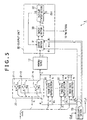
logic operation units 10, i.e., the use ofmemory devices 12 arranged inparallel, the embodiments of the present disclosure are not limited thereby. According to the invention, thememory device 12 is used on a time-sharing basis. Alogic operation unit 1 according to the embodiment of the disclosure is structured to include, as shown inFIG. 5 , n three-state buffer sections 20, amemory device 12, aclock supply section 25, and anoutput unit 30. Each three-state buffer section 20 includes N three-state buffers 21(N=8 in this example). Theoutput unit 30 includes anoutput section 31, a flip-flop circuit section 32, and aswitch section 33. The components already explained above in conjunction with the preceding examples are designated by the same reference characters, and their explanations are omitted hereunder where redundant. In this example, thememory device 12 is assumed to store the data shown inFIG. 3 . - Each three-
state buffer 21 has an input terminal X, an output terminal Y, and a gate terminal G. As long as the input to the gate terminal G remains "0," the three-state buffer 21 holds the output terminal Y in a high-impedance state "Z" regardless of the input to the input terminal X. The three-state buffer 21, if its output terminal Y is brought into the high-impedance state, is in an insulated (i.e., disconnected) state when viewed from the destination to which the output terminal Y is connected. - In the embodiment of the disclosure, 8n three-
state buffers 21 are divided into groups of eight, e.g., the first through the eighth three-state buffers 21_1 through 21_8 making up the first group, the ninth through the 16th three-state buffers 21-9 through 21_16 making up the second group, and so on. The gate terminals G of the three-state buffers 21 belonging to the same group are supplied with the same signal from theclock supply section 25. This signal will be discussed later in more detail. The bits in the data D that is 8xn bits long and subject to the logical operation are inputted successively starting from the MSB (or LSB) to the input terminal X_i of the i-th three-state buffer 21_i. - The output terminal Y_i of the i-th three-state buffer 21_i is connected to the (i mod 8) -th pin on the address bus of the
memory device 12. In this context, (i mod k) means the remainder left over when i is divided by k. - As shown in
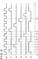
FIG. 6 , theclock supply section 25 generates and outputs a clock signal CLK that rises and falls in a periodically repeated manner. Theclock supply section 25 also generates n sub clock signals ϕi (i=1, 2, ···, n; n is the number given by dividing the number of bits 8n subject to the logical operation by the address bus width, i.e. 8, of the memory device 12).FIG. 6 shows sub clock signals ϕ1, ϕ2, ϕ3, and ϕ4 in effect when n=4, as well as a sub clock signal ϕ0. - The rising or falling timing of the sub clock signal ϕ1 is as follows . When the clock signal CLK rises for the j -th time after a given point in time (e.g., t2), the sub clock signal ϕi (i=(j mod n)+1) is caused to rise. When the clock signal CLK falls for the j-th time after t2, the sub clock signal ϕi (i=(j mod n)+1) is caused to fall. In this case, the sub clock signal ϕi (i≠(j mod n)+1) is held at the Low state.
- In
FIG. 6 (where n=4), for example, when the clock signal CLK rises (at t3) for the first time after the given point in time t2, the sub clock signal ϕ2 satisfying i=(1 mod 4)+1=2 rises. When the clock signal CLK falls (at t4) for the first time after the given time t2, the sub clock signal ϕ2 satisfying i=(1 mod 4)+1=2 falls. - The
clock supply section 25 also generates the sub clock signal ϕ0 as follows. If (j mod n)=0 is satisfied when the clock signal CLK rises for the j-th time after the given time, the sub clock signal cp0 rises. The sub clock signal cp0 falls by the time the clock signal CLK rises for the n-th time, such as when the clock signal CLK rises for the n/2-th time or falls for the (n-1)/2-th time. - Specifically, in the example of
FIG. 6 , after the given time t2 when the clock signal CLK rises for the fourth time (at t9) (4 mod 4)=0 is satisfied. At this moment, theclock supply section 25 performs control to cause the sub clock signal cp0 to rise. Thereafter (past t9), theclock supply section 25 performs control to let the sub clock signal cp0 fall by the time the clock signal CLK falls for the (n/2+1)-th time or the ((n-1)/2+1)-th time (at t14; it is assumed here that n/2+1=3rd time). In the example ofFIG. 6 , the sub clock signal cp0 is controlled to fall when the clock signal CLK rises immediately before the clock signal CLK falls for the (n/2+1)-th time, i.e., for the third time, after time t9. - The
clock supply section 25 supplies the sub clock signal ϕ1 to the first through the eighth three-state buffers 21_1 through 21_8, the sub clock signal ϕ2 to the ninth through the 16th three-state buffers 21_9 through 21_16, and so on, thus supplying the sub clock signal ϕ([(p-1)/8]+1) to each of the eight three-state buffers 21_p (p is an integer of at least 1). Here, [*] means the largest integer not exceeding *. - The three-
state buffers 21 and theclock supply section 25 working as described above implement bit conversion or time-shared extracting means that receives the input of a bit string of M bits (M is an integer larger than N), extracts an N-bit string from the input M-bit string, and outputs the extracted N-bit string to thememory device 12 on a time-sharing basis. - At the time the clock signal CLK from the
clock supply section 25 falls while the sub clock signal ϕn (n is the number obtained by dividing the number of bits 8n subject to the logical operation by theaddress bus width 8 of the memory device 12) does not fall, theoutput section 31 of theoutput unit 30 receives the input of a 1-bit signal from the flip-flop circuit section 32 and holds the received signal in a buffer (not shown) . The next time the clock signal CLK rises, theoutput section 31 reads from the data in thememory device 12 the data stored at the address represented by the bit string outputted from the three-state buffers 21. Depending on whether the 1-bit signal held in the buffer is "0" or "1," theoutput section 31 selectively outputs from the retrieved data either the bit indicating the result of the logical operation or the bit indicating the inverse of the logical operation result. - In one example according to the embodiment, if the bit held in the buffer is "0," the
output section 31 outputs the MSB (bit indicating the result of the logical operation) from the data read from thememory device 12 to theswitch section 33. If the bit held in the buffer is "1," theoutput section 31 outputs the next MSB (i.e., bit indicating the inverse of the logical operation result) from the data read from thememory device 12 to theswitch action 33. Theoutput section 31 continues the output until the clock signal CLK falls next time. - The
output section 31 further controls theswitch section 33, as is discussed later. Specifically, at the time the sub clock signal ϕn (n is the number obtained by dividing the number of bits 8n subject to the logical operation by theaddress bus width 8 of the memory device 12) from theclock supply section 25 rises, theoutput section 31 sets the destination of the output from theswitch section 33, to be explained later, to the outside. The next time the clock signal CLK from theclock supply section 25 rises, theoutput section 31 sets the the destination of the output from theswitch section 33 to the flip-flop circuit section 32. - Furthermore, at the time the sub clock signal ϕn from
clock supply section 25 falls, theoutput section 31 holds the "0" bit in the buffer regardless of the output of the flip-flop circuit section 32. This operation is called the reset operation of the output section in the description that follows. - The flip-
flop circuit section 32 is structured to include, for example, a D-type flip-flop circuit. Specifically, a D terminal (input terminal) of the flip-flop circuit 24 receives the output from theoutput section 31. The C terminal (clock terminal) of the flip-flop circuit 24 receives the input of the clock signal CLK from theclock supply section 25. At the time the clock signal CLK rises, the flip-flop circuit section 32 holds the bit inputted to the D terminal (input terminal) and outputs a signal representative of that bit to an output terminal Q. This output is continued even when the clock signal CLK falls. The bit outputted from the output terminal Q is inputted to theoutput section 31 as the output from the flip-flop circuit section 32. - Under control of the
output section 31, theswitch section 33 selectively outputs the 1-bit information from theoutput section 31 either to the flip-flop circuit section 32 or to the outside. - Explained below are the operation of a
logic operation device 1 according to one embodiment of the present disclosure. It is assumed here that what is received is the input of data D of M=N×n bits (address bus width N of thememory device 12 is multiplied by an integer n; the i-th bit in the data D is bi (i=1, 2, ···, N×n)) subject to the exclusive-OR operation as a logical operation, for example. The i-th bit starting from the MSB (or LSB) is inputted successively to the i-th three-state buffer 21_i. - The
logic operation device 1 works as follows : With the reset operation performed (at time t0 inFIG. 6 ), theoutput section 31 holds the "0" bit in the buffer. The next time the clock signal CLK from theclock supply section 25 rises (at time t1 inFIG. 6 ), the three-state buffers 21_1 through 21_8 feed the input bits b1, b2, ···, and b8 onto the address bus of thememory device 12. - From the data in the
memory device 12, theoutput section 31 reads the data stored at the address represented by the bit string outputted from the three-state buffers 21_1 through 21_8. At this moment, the buffer of theoutput section 31 holds the "0" bit, so that theoutput section 31 outputs from the data retrieved from thememory device 12 the MSB (bit indicating the result of the logical operation) as a first-time operation result R1. The output R1 is sent to the flip-flop circuit section 32 via theswitch section 33 and is held in the flip-flop circuit section 32. - Then, when the clock signal CLK from the
clock supply section 25 falls (at time t2 inFIG. 6 ), the outputs from the three-state buffers 21_1 through 21_8 are in the high-impedance state. Theoutput section 31 then receives the preceding operation result R1 from the flip-flop circuit 32 and holds it in the buffer. - When the clock signal CLK from the
clock supply section 25 rises (at time t3 inFIG. 6 ), the three-state buffers 21_9 through 21_16 feed the input bits b9, b10, ···, and b16 onto the address bus of thememory device 12. - From the data in the
memory device 12, theoutput section 31 reads the data stored at the address represented by the bit string composed of bits outputted from the three-state buffers 21_9 through 21_16. If the buffer holds a "0" bit (if the operation result R1 is "0"), theoutput section 31 outputs the MSB (bit indicating the result of the logical operation) as a second-time operation result R2, from among the data retrieved from thememory device 12. If the buffer holds a "1" bit (if the operation result R1 is "1"), theoutput section 31 outputs the next most significant bit (bit indicating the inverse of the logical operation result) as the second-time operation result R2, from among the data retrieved from thememory device 12. The output R2 is sent to the flip-flop circuit section 32 via theswitch section 33 and is held in the flip-flop circuit section 32. - Thereafter, similar processes are performed. At the time the sub clock signal ϕn from the
clock supply section 25 rises, theoutput section 31 sets the destination of the output from theswitch section 33 to the outside. At this moment, theoutput section 31 reads the data stored at the address represented by the bit string composed of the bits outputted from three-state buffers 21_(8×(n-1)+1) through 21_(8n) in thememory device 12. If the buffer holds the "0" bit (if the operation result Rn-1 is "0"), theoutput section 31 outputs the MSB (bit indicating the result of the logical operation) as the operation result R, from among the data retrieved from thememory device 12. If the buffer holds the "1" bit (if the operation result Rn-1 is "1"), theoutput section 31 outputs the next MSB (bit indicating the inverse of the logical operation result) as the operation result R, from among the data retrieved from thememory device 12. This output is fed to the outside via theswitch section 33. - Then, when the clock signal CLK falls, the
output section 31 performs the reset operation. When the clock signal CLK rises next, theoutput section 31 sets the flip-flop circuit section 32 as the destination to which the output of theswitch section 33 is directed. - According to the invention, every time the N-bit string is outputted on a time-sharing basis, the
output section 31 functions as the means to selectively output either the bit indicating the result of the logical operation performed between the bits retrieved by accessing the memory device using the previously outputted bits, or the bit indicating the inverse of the logical operation result. - The n-th time around, the
output section 31 outputs as the operation result R the result of the logical operation (exclusive-OR operation in this example) performed on the bits included in the data D of 8×n bits. - An example of the output unit where the logical operation is performed on a time-sharing basis is not limited to that disclosed above. Since each address in the
memory device 12 accommodates 8-bit data, there maybe provided alternatively another output device by making effective use of the 8-bit width, as explained below. - An
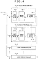
arithmetic logic unit 1 according to still another embodiment of the present disclosure is structured to include, as shown inFIG. 7 , 8×n (address bus width N=8 for the memory device 12) three-state buffers 21 (as in the example ofFIG. 5 , each three-state buffer section 20 is formed by a groups of 8 three-state buffers), amemory device 12, aclock supply section 25, and anoutput unit 40. Theoutput unit 40 is structured to include fourselector sections - In the
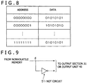
memory device 12, as shown inFIG. 8 , combinations of the result of the logical operation based on the bit string a1, a2, ···, and a8 with the bit indicating the inverse of the logical operation result are arranged repeatedly at locations each represented by an 8-bit address A (represented by the bit string a1, a2, ···, and a8). That is, in this example, the result of the logical operation is stored in each odd-numbered bit position of the data stored at each address location, and the inverse of the logical operation result is stored in each even-numbered bit position of the data thus stored. - The
selector section 41a in theoutput unit 40 is connected with a signal line d1 representative of the MSB and with a signal line d2 representative of the next MSB, out of the signal lines making up the data bus of thememory device 12. Theselector section 41a also receives an externally inputted 1-bit signal. - At the time the sub clock signal ϕ1 from the
clock supply section 25 rises, theselector section 41a reads the data, stored at the address represented by the bit string output from the three-state buffers 21 from among the data in thememory device 12, and latches the retrieved data. Depending on whether the externally inputted 1-bit signal is "0" or "1, " theselector section 41a selectively latches from the retrieved data either the MSB (1 bit) indicating the result of the logical operation or the next MSB indicating the inverse of the logical operation result, and outputs the latched bit. - In this example, if the externally inputted bit is "0," the
selector section 41a selectively latches the MSB (indicating the result of the logical operation, output through the signal line d1) from among the data retrieved from thememory device 12 and outputs the latched bit. If the externally inputted bit is "1," theselector section 41a selectively latches the next MSB (outputted through the signal line d2, indicating the inverse of the logical operation result) from among the data retrieved from thememory device 12 and outputs the latched bit. - The
selector section 41b is connected with a signal line d3 nearer to the MSB and with a signal line d4 that is the next bit, the signal lines making up the data bus of thememory device 12. Theselector section 41b also receives the 1-bit signal from theselector section 41a. - At the time the sub clock signal ϕ2 inputted from the
clock supply section 25 rises, theselector section 41b reads the data stored at the address represented by the bit string outputted from the three-state buffers 21 in thememory device 12, and latches the retrieved data. Depending on whether the 1-bit signal received from theselector section 41a is "0" or "1, " theselector section 41b selectively latches from the retrieved data either the MSB-side bit indicating the result of the logical operation or the next bit indicating the inverse of the logical operation result, and outputs the latched bit. - In this example, if the bit received from the
selector section 41a is "0," theselector section 41b selectively latches the MSB-side bit (indicating the result of the logical operation, outputted through the signal line d3) from among the data retrieved from thememory device 12 and outputs the latched bit. If the bit received from theselector section 41a is "1, " theselector section 41b selectively latches from the data retrieved from thememory device 12 the bit through the signal line d4 next to the signal line d3 (the bit indicating the inverse of the logical operation result) and outputs the latched bit. - The
selector section 41c is connected with a signal line d5 nearer to the MSB and with a signal line d6 that is the next bit, out of the signal lines making up the data bus of thememory device 12. Theselector section 41c also receives the 1-bit signal outputted from theselector section 41b. - At the time the sub clock signal ϕ3 from the
clock supply section 25 rises, theselector section 41c reads the data stored at the address represented by the bit string outputted from the three-state buffers 21 in thememory device 12, and latches the retrieved data. If the bit received from theselector section 41b is "0," theselector section 41c of this example selectively latches the MSB-side bit (indicating the result of the logical operation, output through the signal line d5) from among the data retrieved from thememory device 12, and outputs the latched bit. If the bit received from theselector section 41b is "1," theselector section 41c selectively latches from the data retrieved from thememory device 12 the bit represented through the signal line d6 next to the signal line d5 (the bit indicating the inverse of the logical operation result), and outputs the latched bit. - The
selector section 41d is connected with a signal line d7 on the side of the MSB and with a signal line d8 that is the next bit, out of the signal lines making up the data bus of thememory device 12. Theselector section 41d further receives the 1-bit signal from theselector section 41c. - At the time the sub clock signal ϕ4 from the
clock supply section 25 rises, theselector section 41d reads the data stored at the address represented by the bit string outputted from the three-state buffers 21 in thememory device 12, and latches the retrieved data. If the bit received from theselector section 41c is "0, " theselector section 41d of this example selectively latches the MSB-side bit (indicating the result of the logical operation, outputted through the signal line d7) from among the data retrieved from thememory device 12, and outputs the latched bit. If the bit received from theselector section 41b is "1," theselector section 41c selectively latches from among the data retrieved from thememory device 12 the bit represented through the signal line d8 next to the signal line d7 (the bit indicating the inverse of the logical operation result), and outputs the latched bit. The output of theselector section 41d is outputted to the outside. - The operation of the
logic operation device 1 according to the embodiment is explained below. It is assumed here that what is received is the input of data D of M (=N×n) bits (address bus width N of thememory device 12 is multiplied by an integer n; the i-th bit in the data D is referred to as bi (i=1, 2, ···, N×n)) subject to the exclusive-OR operation as the logical operation, for example. The i-th bit counted from the MSB (or LSB) is input successively to the i-th three-state buffer 21_i. - The
logic operation device 1 works as follows. After the output of theselector section 41d has been delivered(at time t0 inFIG. 6 ),and then when the next time the clock signal CLK and the sub clock signal ϕ1 from theclock supply section 25 rise (at time t1 inFIG. 6 ), the three-state buffers 21_1 through 21_8 feed the input bits b1, b2, ···, and b8 onto the address bus of thememory device 12. - At this moment, the
selector section 41a in theoutput unit 40 reads the data stored at the address represented by the bit string composed of the bits outputted respectively from the three-state buffers 21_1 through 21_8 in thememory device 12. It is assumed that a "0" signal is being inputted to theselector section 41a from the outside. Theselector section 41a has a latch that latches the MSB (data outputted though the signal line d1 of the data bus, indicating the result of the logical operation) from among the data retrieved from thememory device 12 as an operation result R1, and outputs the latched result R1 at the time the sub clock signal ϕ1rises (at time t1 inFIG. 6 ). The output R1 is sent to theselector section 41b. - The
selector section 41b receives the output R1. Then when the clock signal CLK and the sub clock signal ϕ2 from theclock supply section 25 rise (at time t3 inFIG. 6 ), the three-state buffers 21_9 through 21_16 feed the input bits b9, b10, ···, and b16 onto the address bus of thememory device 12. - The
selector section 41b reads the data stored at the address represented by the bit string composed of bits respectively outputted from the three-state buffers 21_9 through 21_16 in thememory device 12. If the bit received from theselector section 41a is "0" (i.e., if the operation result R1 is "0"), theselector section 41b latches the MSB-side bit (outputted through the signal line d3 of the data bus, indicating the result of the logical operation) as an operation result R2 at the time the sub clock signal ϕ2 rises (at time t3 inFIG. 6 ) from among the data retrieved from thememory device 12, and outputs the latched result R2. If the bit input from theselector section 41a is "1" (i.e., if the operation result R1 is "1"), theselector section 41b latches from the data retrieved from thememory device 12 the bit outputted through the signal line d4 (i.e. the bit indicating the inverse of the logical operation result) as the operation result R2 at the time the sub clock signal ϕ2 rises (at time t3 inFIG. 6 ), and outputs the latched result R2. The output R2 is received by theselector section 41c. - The
subsequent selector sections 41c··· operate in like manner. At the time the sub clock signal ϕ4 rises, the three-state buffers 21_25 through 21_32 feed the inputted bits b25, b26, ···, and b32 onto the address bus of thememory device 12. This causes theselector section 41d to read the data stored at the address represented by the bit string composed of the bits outputted respectively from the three-state buffers 21_25 through 21_32 in thememory device 12. - If the bit input from the
selector section 41c is "0" (i.e. , if the operation result R3 is "0"), theselector section 41d latches the MSB-side bit (output though the signal line d7 of the data bus, indicating the result of the logical operation) of the data retrieved from thememory device 12 as the operation result R at the time the sub clock signal ϕ4 rises, and outputs the latched result R. If the bit input from theselector section 41c is "1" (if the operation result R3 is "1"), theselector section 41d latches from the data retrieved from thememory device 12 the output through the signal line d8 (i.e. the bit indicating the inverse of the logical operation result) as the operation result R at the time the sub clock signal ϕ4 rises, and outputs the latched result R. - In the embodiment described above, when the N-bit string is output on a time-sharing basis, each selector section 41 in the
output unit 40 functions as the means to selectively output either the bit indicating the result of the logical operation performed between the bits retrieved by accessing the memory device using the previously output bits, or the bit indicating the inverse of the logical operation result. Every four cycles of this time-sharing, theoutput unit 40 outputs as the operation result R the result of the logical operation (exclusive-OR operation in this example) performed on each of the bits in the data D of 32 bits (=8×4). - In this manner, when the N-bit string is output on a time-sharing basis, the
output unit 40 of the embodiment functions as the means to selectively output either the bit indicating the result of the logical operation performed between the bits retrieved by accessing the memory device using the previously output bits, or the bit indicating the inverse of the logical operation result. - In the above description of the embodiments, where the lookup table in
FIG. 3 is used, theoutput section 31 or theoutput unit 40 is shown to switch between the output of either an odd-numbered bit or an even-numbered bit in the data retrieved from thememory device 12 using the output from the previous stage. However, this concept does not limit the scope of the present disclosure. For example, as shown inFIG. 9 , an inverting (NOT)circuit 51 may be connected with a signal line d (on which is outputted the logical operation result using the bit string represented by the address input to the memory device 12) output from thememory device 12, so as to obtain the bit indicating the inverse of the logical operation result using the bit string represented by the address inputted to thememory device 12. In this case, theoutput section 31 or theoutput unit 40 selects either the output of the signal line d or that of the NOT circuit 51 (theoutput unit 40 latches the output) using the output from the previous stage, and outputs what is selected. - In the
logic operation device 1 embodying the present disclosure as shown inFIG. 4 ,5 , or7 , what is received is the input of a bit string having the length of the address bus width N of the memory device multiplied by an integer n (e.g., 32 bits long if the address bus width is 8 bits and the integer n is 4), and the result of the logical operation performed on the input bit string is the output of a single bit. In that case, eight sucharithmetic logic devices 1 may be connected in parallel to have their outputs inputted to an 8-input logical operation circuit, whereby the logical operation on N×n×8 bits may be carried out. - Specifically,
FIG. 10 shows a setup having eightlogic operation devices 1 connected in parallel, eachlogic operation device 1 being the one illustrated inFIG. 4 ,5 , or7 and having the lookup table established in thememory device 12 in such a manner that given the input of a bit string of 32 bits (8 bits of the address bus width multiplied by n=4), the exclusive-OR operation is performed on the input bit string. - In the example of
FIG. 10 , the 1-bit output from eachlogic operation device 1 is input to the 8-input XOR circuit 100, the same as the one shown inFIG. 11 , whereby the exclusive-OR operation is performed on the bits to obtain one bit indicating the result of the exclusive-OR operation. According to this circuit structure, a circuit of relatively small scale still enables the exclusive-OR operation to be performed between the bits in the bit string of 256 bits (=8×4×8). - 1 Logic operation device, 10 logic operation unit, 11 Input buffer section, 12 Memory device, 13, 31 Output section, 20 Three-state buffer section, 21 Three-state buffer, 25 Clock supply section, 30, 40 Output unit, 32 Flip-flop circuit section, 33 Switch section, 41 Selector section, 51NOTcircuit, 1008-input XOR circuit, 200 2-input XOR circuit.
- In the drawings:
-
- 1: LOGIC OPERATION DEVICE
- 10: LOGIC OPERATION UNIT
- 11: INPUT BUFFER SECTION
- 12: MEMORY DEVICE
- 13: OUTPUT SECTION
- ADDRESS
DATA -
- 10-1 to 10-n: LOGIC OPERATION UNIT
- 11-1, 11-2: INPUT BUFFER SECTION
- 12-1, 12-2: MEMORY DEVICE
- 13-1, 13-2: OUTPUT SECTION
-
- 12: MEMORY DEVICE
- 20: THREE-STATE BUFFER SECTION
- 25: CLOCK SUPPLY SECTION
- 30: OUTPUT UNIT
- 31: OUTPUT SECTION
- 32: FLIP-FLOP CIRCUIT SECTION
- 33: SWITCH SECTION
- TO OUTSIDE
-
- 12: MEMORY DEVICE
- 20: THREE-STATE BUFFER SECTION
- 25: CLOCK SUPPLY SECTION
- 40: OUTPUT UNIT
- 41a to 41d: SELECTOR SECTION
-
- FROM NONVOLATILE MEMORY
- TO
OUTPUT SECTION 31 OROUTPUT UNIT 40 - 51: NOT CIRCUIT
- 100: 8-INPUT LOGICAL OPERATION CIRCUIT
OUTPUT
Claims (3)
- A logic operation device (1) comprising:a memory device (12) configured to receive an input of a N-bit long bit string and to store a lookup table, N being an integer of at least 2, the lookup table storing multiple-bit long data in an address represented by the input bit string, and a bit representative of a result of a logical operation performed between bits included in the input bit string being stored in a part of the multiple-bit long data; andan output means (30, 40) configured to access the memory device (12) and outputs the bits included in the data stored at the address represented by the received bit string, characterized in that it further comprises:a time-shared extracting means (21, 25) configured to receive the input of a bit string M bits long, M being an integer larger than N, the time-shared extracting means (21, 25) extracting an N-bit string from the M-bit string to output the extracted N-bit string to the memory device (12) on a time-sharing basis;wherein the output means (30, 40) is configured to output, at the time the N-bit string is output on a time-sharing basis, selectively either the bit indicating the result of the logical operation performed between the bits retrieved by accessing the memory device (12) using the previously output bits, or a bit indicating an inverse of the logical operation result.
- The logic operation device (1) according to claim 1,
characterized in that the data stored in the memory device (12) includes a bit indicating the result of the logical operation performed between the bits in the input bit string and a bit indicating an inverse of the logical operation result; and
the output means (30, 40) configured to selectively output either the bit indicating the result of the logical operation performed between the bits or the bit indicating the inverse of the logical operation result. - The logic operation device (1) according to claim 1 or claim 2,
characterized in that the result of the logical operation stored in the memory device (12) is the result of an exclusive-OR operation performed between the bits included in the input bit string.
Applications Claiming Priority (2)
| Application Number | Priority Date | Filing Date | Title |
|---|---|---|---|
| JP2013157090A JP6219631B2 (en) | 2013-07-29 | 2013-07-29 | Logic unit |
| PCT/JP2014/065245 WO2015015905A1 (en) | 2013-07-29 | 2014-06-09 | Arithmetic logic device |
Publications (3)
| Publication Number | Publication Date |
|---|---|
| EP3029839A1 EP3029839A1 (en) | 2016-06-08 |
| EP3029839A4 EP3029839A4 (en) | 2017-04-19 |
| EP3029839B1 true EP3029839B1 (en) | 2018-05-30 |
Family
ID=52431449
Family Applications (1)
| Application Number | Title | Priority Date | Filing Date |
|---|---|---|---|
| EP14831256.4A Active EP3029839B1 (en) | 2013-07-29 | 2014-06-09 | Arithmetic logic device |
Country Status (6)
| Country | Link |
|---|---|
| US (1) | US9866219B2 (en) |
| EP (1) | EP3029839B1 (en) |
| JP (1) | JP6219631B2 (en) |
| CN (1) | CN105432018B (en) |
| TW (1) | TWI562059B (en) |
| WO (1) | WO2015015905A1 (en) |
Families Citing this family (3)
| Publication number | Priority date | Publication date | Assignee | Title |
|---|---|---|---|---|
| US10990389B2 (en) | 2019-04-29 | 2021-04-27 | Micron Technology, Inc. | Bit string operations using a computing tile |
| US10778245B1 (en) * | 2019-08-20 | 2020-09-15 | Micron Technology, Inc. | Bit string conversion |
| US11227641B1 (en) * | 2020-07-21 | 2022-01-18 | Micron Technology, Inc. | Arithmetic operations in memory |
Family Cites Families (21)
| Publication number | Priority date | Publication date | Assignee | Title |
|---|---|---|---|---|
| JP2853154B2 (en) * | 1988-08-19 | 1999-02-03 | 富士ゼロックス株式会社 | Programmable fuzzy logic circuit |
| JPH0457112A (en) * | 1990-06-26 | 1992-02-24 | Mitsubishi Electric Corp | Arithmetic unit |
| US6049223A (en) * | 1995-03-22 | 2000-04-11 | Altera Corporation | Programmable logic array integrated circuit with general-purpose memory configurable as a random access or FIFO memory |
| US6487190B1 (en) * | 1996-06-27 | 2002-11-26 | Interdigital Technology Corporation | Efficient multichannel filtering for CDMA modems |
| JP3533825B2 (en) | 1996-04-26 | 2004-05-31 | 日本電信電話株式会社 | Logical operation unit and logical operation device |
| GB9900432D0 (en) * | 1999-01-08 | 1999-02-24 | Xilinx Inc | Linear feedback shift register in a progammable gate array |
| US6555398B1 (en) * | 1999-10-22 | 2003-04-29 | Magic Corporation | Software programmable multiple function integrated circuit module |
| US6463003B2 (en) * | 2000-06-07 | 2002-10-08 | Advanced Micro Devices, Inc. | Power saving scheme for burst mode implementation during reading of data from a memory device |
| US7111224B1 (en) * | 2001-02-28 | 2006-09-19 | Xilinx, Inc. | FPGA configuration memory with built-in error correction mechanism |
| US20030068038A1 (en) * | 2001-09-28 | 2003-04-10 | Bedros Hanounik | Method and apparatus for encrypting data |
| JP2003281516A (en) * | 2002-03-22 | 2003-10-03 | Canon Inc | Image processor and its method |
| US7157933B1 (en) * | 2004-02-14 | 2007-01-02 | Herman Schmit | Configurable circuits, IC's, and systems |
| US7330050B2 (en) * | 2004-11-08 | 2008-02-12 | Tabula, Inc. | Storage elements for a configurable IC and method and apparatus for accessing data stored in the storage elements |
| US7129864B2 (en) * | 2004-12-31 | 2006-10-31 | Intel Corporation | Fast compact decoder for huffman codes |
| JP2008527878A (en) * | 2005-01-14 | 2008-07-24 | エヌエックスピー ビー ヴィ | Channel coding |
| JP4827695B2 (en) * | 2006-11-13 | 2011-11-30 | パナソニック株式会社 | Wireless receiver |
| US7768430B1 (en) * | 2008-05-20 | 2010-08-03 | Altera Corporation | Look-up table based memory |
| US7663957B2 (en) * | 2008-05-27 | 2010-02-16 | Via Technologies, Inc. | Microprocessor with program-accessible re-writable non-volatile state embodied in blowable fuses of the microprocessor |
| JP5261738B2 (en) * | 2009-01-15 | 2013-08-14 | 国立大学法人広島大学 | Semiconductor device |
| US9747105B2 (en) * | 2009-12-17 | 2017-08-29 | Intel Corporation | Method and apparatus for performing a shift and exclusive or operation in a single instruction |
| CN104012000B (en) * | 2011-10-24 | 2017-03-08 | 天工方案公司 | Dual-mode power amplifier control interface |
-
2013
- 2013-07-29 JP JP2013157090A patent/JP6219631B2/en active Active
-
2014
- 2014-06-03 TW TW103119252A patent/TWI562059B/en active
- 2014-06-09 EP EP14831256.4A patent/EP3029839B1/en active Active
- 2014-06-09 US US14/908,339 patent/US9866219B2/en active Active
- 2014-06-09 WO PCT/JP2014/065245 patent/WO2015015905A1/en active Application Filing
- 2014-06-09 CN CN201480042802.7A patent/CN105432018B/en active Active
Non-Patent Citations (1)
| Title |
|---|
| None * |
Also Published As
| Publication number | Publication date |
|---|---|
| EP3029839A4 (en) | 2017-04-19 |
| JP2015026341A (en) | 2015-02-05 |
| US9866219B2 (en) | 2018-01-09 |
| CN105432018A (en) | 2016-03-23 |
| JP6219631B2 (en) | 2017-10-25 |
| EP3029839A1 (en) | 2016-06-08 |
| CN105432018B (en) | 2019-01-08 |
| TWI562059B (en) | 2016-12-11 |
| WO2015015905A1 (en) | 2015-02-05 |
| US20160211851A1 (en) | 2016-07-21 |
| TW201506779A (en) | 2015-02-16 |
Similar Documents
| Publication | Publication Date | Title |
|---|---|---|
| JP5141910B2 (en) | Encryption and decryption processing method and system for realizing SMS4 encryption algorithm | |
| CN202512559U (en) | Variable structure for random number generator | |
| JP3235534B2 (en) | Parallel-parallel converter, parallel-serial converter using the same, and serial-parallel converter | |
| US10419004B2 (en) | NVFF monotonic counter and method of implementing same | |
| EP3029839B1 (en) | Arithmetic logic device | |
| WO2012016588A1 (en) | Bit sequence generator | |
| US9166795B2 (en) | Device and method for forming a signature | |
| CN108521327B (en) | Power-off storage type SIMON encryption circuit | |
| CN112820225B (en) | Data cache circuit, display panel and display device | |
| JP2015026341A5 (en) | ||
| CN112821889B (en) | Output control circuit, data transmission method and electronic equipment | |
| RU154062U1 (en) | DEVICE FOR SEARCHING TRANSFERS | |
| US10170166B1 (en) | Data transmission apparatus for memory and data transmission method thereof | |
| JP2002111781A (en) | Memory for packet communication and data write/read method used for the same | |
| KR970049702A (en) | High speed barrel shifter | |
| JP2019149070A (en) | Serial interface circuit, semiconductor device, and serial-parallel conversion method | |
| US7847595B2 (en) | Input circuit and semiconductor integrated circuit comprising the input circuit | |
| JP2008193516A (en) | Random error signal generator | |
| JP3936476B2 (en) | Code generator | |
| KR930008038B1 (en) | Memory controller | |
| US8095848B1 (en) | Multi-byte cyclic redundancy check calculation circuit and method of operating the same | |
| JP4252406B2 (en) | Data converter | |
| JPH1195862A (en) | Pattern generation circuit | |
| CN110609672A (en) | True random number generating device and generating method thereof | |
| JP2005073146A (en) | Crc check circuit |
Legal Events
| Date | Code | Title | Description |
|---|---|---|---|
| PUAI | Public reference made under article 153(3) epc to a published international application that has entered the european phase |
Free format text: ORIGINAL CODE: 0009012 |
|
| 17P | Request for examination filed |
Effective date: 20160212 |
|
| AK | Designated contracting states |
Kind code of ref document: A1 Designated state(s): AL AT BE BG CH CY CZ DE DK EE ES FI FR GB GR HR HU IE IS IT LI LT LU LV MC MK MT NL NO PL PT RO RS SE SI SK SM TR |
|
| AX | Request for extension of the european patent |
Extension state: BA ME |
|
| DAX | Request for extension of the european patent (deleted) | ||
| A4 | Supplementary search report drawn up and despatched |
Effective date: 20170320 |
|
| RIC1 | Information provided on ipc code assigned before grant |
Ipc: H03K 19/21 20060101AFI20170314BHEP Ipc: G06F 1/02 20060101ALI20170314BHEP |
|
| GRAP | Despatch of communication of intention to grant a patent |
Free format text: ORIGINAL CODE: EPIDOSNIGR1 |
|
| INTG | Intention to grant announced |
Effective date: 20171206 |
|
| GRAS | Grant fee paid |
Free format text: ORIGINAL CODE: EPIDOSNIGR3 |
|
| GRAA | (expected) grant |
Free format text: ORIGINAL CODE: 0009210 |
|
| RAP1 | Party data changed (applicant data changed or rights of an application transferred) |
Owner name: MEISEI GAKUEN Owner name: BUFFALO INC. |
|
| AK | Designated contracting states |
Kind code of ref document: B1 Designated state(s): AL AT BE BG CH CY CZ DE DK EE ES FI FR GB GR HR HU IE IS IT LI LT LU LV MC MK MT NL NO PL PT RO RS SE SI SK SM TR |
|
| REG | Reference to a national code |
Ref country code: GB Ref legal event code: FG4D |
|
| REG | Reference to a national code |
Ref country code: CH Ref legal event code: EP |
|
| REG | Reference to a national code |
Ref country code: AT Ref legal event code: REF Ref document number: 1004649 Country of ref document: AT Kind code of ref document: T Effective date: 20180615 |
|
| REG | Reference to a national code |
Ref country code: IE Ref legal event code: FG4D |
|
| REG | Reference to a national code |
Ref country code: DE Ref legal event code: R096 Ref document number: 602014026457 Country of ref document: DE |
|
| REG | Reference to a national code |
Ref country code: NL Ref legal event code: MP Effective date: 20180530 |
|
| REG | Reference to a national code |
Ref country code: LT Ref legal event code: MG4D |
|
| PG25 | Lapsed in a contracting state [announced via postgrant information from national office to epo] |
Ref country code: FI Free format text: LAPSE BECAUSE OF FAILURE TO SUBMIT A TRANSLATION OF THE DESCRIPTION OR TO PAY THE FEE WITHIN THE PRESCRIBED TIME-LIMIT Effective date: 20180530 Ref country code: NO Free format text: LAPSE BECAUSE OF FAILURE TO SUBMIT A TRANSLATION OF THE DESCRIPTION OR TO PAY THE FEE WITHIN THE PRESCRIBED TIME-LIMIT Effective date: 20180830 Ref country code: BG Free format text: LAPSE BECAUSE OF FAILURE TO SUBMIT A TRANSLATION OF THE DESCRIPTION OR TO PAY THE FEE WITHIN THE PRESCRIBED TIME-LIMIT Effective date: 20180830 Ref country code: LT Free format text: LAPSE BECAUSE OF FAILURE TO SUBMIT A TRANSLATION OF THE DESCRIPTION OR TO PAY THE FEE WITHIN THE PRESCRIBED TIME-LIMIT Effective date: 20180530 Ref country code: CY Free format text: LAPSE BECAUSE OF FAILURE TO SUBMIT A TRANSLATION OF THE DESCRIPTION OR TO PAY THE FEE WITHIN THE PRESCRIBED TIME-LIMIT Effective date: 20180530 Ref country code: ES Free format text: LAPSE BECAUSE OF FAILURE TO SUBMIT A TRANSLATION OF THE DESCRIPTION OR TO PAY THE FEE WITHIN THE PRESCRIBED TIME-LIMIT Effective date: 20180530 Ref country code: SE Free format text: LAPSE BECAUSE OF FAILURE TO SUBMIT A TRANSLATION OF THE DESCRIPTION OR TO PAY THE FEE WITHIN THE PRESCRIBED TIME-LIMIT Effective date: 20180530 |
|
| PG25 | Lapsed in a contracting state [announced via postgrant information from national office to epo] |
Ref country code: RS Free format text: LAPSE BECAUSE OF FAILURE TO SUBMIT A TRANSLATION OF THE DESCRIPTION OR TO PAY THE FEE WITHIN THE PRESCRIBED TIME-LIMIT Effective date: 20180530 Ref country code: HR Free format text: LAPSE BECAUSE OF FAILURE TO SUBMIT A TRANSLATION OF THE DESCRIPTION OR TO PAY THE FEE WITHIN THE PRESCRIBED TIME-LIMIT Effective date: 20180530 Ref country code: GR Free format text: LAPSE BECAUSE OF FAILURE TO SUBMIT A TRANSLATION OF THE DESCRIPTION OR TO PAY THE FEE WITHIN THE PRESCRIBED TIME-LIMIT Effective date: 20180831 Ref country code: LV Free format text: LAPSE BECAUSE OF FAILURE TO SUBMIT A TRANSLATION OF THE DESCRIPTION OR TO PAY THE FEE WITHIN THE PRESCRIBED TIME-LIMIT Effective date: 20180530 |
|
| REG | Reference to a national code |
Ref country code: AT Ref legal event code: MK05 Ref document number: 1004649 Country of ref document: AT Kind code of ref document: T Effective date: 20180530 |
|
| PG25 | Lapsed in a contracting state [announced via postgrant information from national office to epo] |
Ref country code: NL Free format text: LAPSE BECAUSE OF FAILURE TO SUBMIT A TRANSLATION OF THE DESCRIPTION OR TO PAY THE FEE WITHIN THE PRESCRIBED TIME-LIMIT Effective date: 20180530 |
|
| PG25 | Lapsed in a contracting state [announced via postgrant information from national office to epo] |
Ref country code: PL Free format text: LAPSE BECAUSE OF FAILURE TO SUBMIT A TRANSLATION OF THE DESCRIPTION OR TO PAY THE FEE WITHIN THE PRESCRIBED TIME-LIMIT Effective date: 20180530 Ref country code: EE Free format text: LAPSE BECAUSE OF FAILURE TO SUBMIT A TRANSLATION OF THE DESCRIPTION OR TO PAY THE FEE WITHIN THE PRESCRIBED TIME-LIMIT Effective date: 20180530 Ref country code: AT Free format text: LAPSE BECAUSE OF FAILURE TO SUBMIT A TRANSLATION OF THE DESCRIPTION OR TO PAY THE FEE WITHIN THE PRESCRIBED TIME-LIMIT Effective date: 20180530 Ref country code: CZ Free format text: LAPSE BECAUSE OF FAILURE TO SUBMIT A TRANSLATION OF THE DESCRIPTION OR TO PAY THE FEE WITHIN THE PRESCRIBED TIME-LIMIT Effective date: 20180530 Ref country code: RO Free format text: LAPSE BECAUSE OF FAILURE TO SUBMIT A TRANSLATION OF THE DESCRIPTION OR TO PAY THE FEE WITHIN THE PRESCRIBED TIME-LIMIT Effective date: 20180530 Ref country code: SK Free format text: LAPSE BECAUSE OF FAILURE TO SUBMIT A TRANSLATION OF THE DESCRIPTION OR TO PAY THE FEE WITHIN THE PRESCRIBED TIME-LIMIT Effective date: 20180530 Ref country code: DK Free format text: LAPSE BECAUSE OF FAILURE TO SUBMIT A TRANSLATION OF THE DESCRIPTION OR TO PAY THE FEE WITHIN THE PRESCRIBED TIME-LIMIT Effective date: 20180530 |
|
| REG | Reference to a national code |
Ref country code: CH Ref legal event code: PL |
|
| PG25 | Lapsed in a contracting state [announced via postgrant information from national office to epo] |
Ref country code: SM Free format text: LAPSE BECAUSE OF FAILURE TO SUBMIT A TRANSLATION OF THE DESCRIPTION OR TO PAY THE FEE WITHIN THE PRESCRIBED TIME-LIMIT Effective date: 20180530 Ref country code: IT Free format text: LAPSE BECAUSE OF FAILURE TO SUBMIT A TRANSLATION OF THE DESCRIPTION OR TO PAY THE FEE WITHIN THE PRESCRIBED TIME-LIMIT Effective date: 20180530 |
|
| REG | Reference to a national code |
Ref country code: DE Ref legal event code: R097 Ref document number: 602014026457 Country of ref document: DE |
|
| REG | Reference to a national code |
Ref country code: BE Ref legal event code: MM Effective date: 20180630 |
|
| REG | Reference to a national code |
Ref country code: IE Ref legal event code: MM4A |
|
| PG25 | Lapsed in a contracting state [announced via postgrant information from national office to epo] |
Ref country code: LU Free format text: LAPSE BECAUSE OF NON-PAYMENT OF DUE FEES Effective date: 20180609 Ref country code: MC Free format text: LAPSE BECAUSE OF FAILURE TO SUBMIT A TRANSLATION OF THE DESCRIPTION OR TO PAY THE FEE WITHIN THE PRESCRIBED TIME-LIMIT Effective date: 20180530 |
|
| PLBE | No opposition filed within time limit |
Free format text: ORIGINAL CODE: 0009261 |
|
| STAA | Information on the status of an ep patent application or granted ep patent |
Free format text: STATUS: NO OPPOSITION FILED WITHIN TIME LIMIT |
|
| GBPC | Gb: european patent ceased through non-payment of renewal fee |
Effective date: 20180830 |
|
| PG25 | Lapsed in a contracting state [announced via postgrant information from national office to epo] |
Ref country code: CH Free format text: LAPSE BECAUSE OF NON-PAYMENT OF DUE FEES Effective date: 20180630 Ref country code: FR Free format text: LAPSE BECAUSE OF NON-PAYMENT OF DUE FEES Effective date: 20180730 Ref country code: LI Free format text: LAPSE BECAUSE OF NON-PAYMENT OF DUE FEES Effective date: 20180630 Ref country code: IE Free format text: LAPSE BECAUSE OF NON-PAYMENT OF DUE FEES Effective date: 20180609 |
|
| 26N | No opposition filed |
Effective date: 20190301 |
|
| PG25 | Lapsed in a contracting state [announced via postgrant information from national office to epo] |
Ref country code: BE Free format text: LAPSE BECAUSE OF NON-PAYMENT OF DUE FEES Effective date: 20180630 Ref country code: SI Free format text: LAPSE BECAUSE OF FAILURE TO SUBMIT A TRANSLATION OF THE DESCRIPTION OR TO PAY THE FEE WITHIN THE PRESCRIBED TIME-LIMIT Effective date: 20180530 |
|
| PG25 | Lapsed in a contracting state [announced via postgrant information from national office to epo] |
Ref country code: GB Free format text: LAPSE BECAUSE OF NON-PAYMENT OF DUE FEES Effective date: 20180830 |
|
| PG25 | Lapsed in a contracting state [announced via postgrant information from national office to epo] |
Ref country code: AL Free format text: LAPSE BECAUSE OF FAILURE TO SUBMIT A TRANSLATION OF THE DESCRIPTION OR TO PAY THE FEE WITHIN THE PRESCRIBED TIME-LIMIT Effective date: 20180530 |
|
| PG25 | Lapsed in a contracting state [announced via postgrant information from national office to epo] |
Ref country code: MT Free format text: LAPSE BECAUSE OF NON-PAYMENT OF DUE FEES Effective date: 20180609 |
|
| PG25 | Lapsed in a contracting state [announced via postgrant information from national office to epo] |
Ref country code: TR Free format text: LAPSE BECAUSE OF FAILURE TO SUBMIT A TRANSLATION OF THE DESCRIPTION OR TO PAY THE FEE WITHIN THE PRESCRIBED TIME-LIMIT Effective date: 20180530 |
|
| PG25 | Lapsed in a contracting state [announced via postgrant information from national office to epo] |
Ref country code: PT Free format text: LAPSE BECAUSE OF FAILURE TO SUBMIT A TRANSLATION OF THE DESCRIPTION OR TO PAY THE FEE WITHIN THE PRESCRIBED TIME-LIMIT Effective date: 20180530 |
|
| PG25 | Lapsed in a contracting state [announced via postgrant information from national office to epo] |
Ref country code: HU Free format text: LAPSE BECAUSE OF FAILURE TO SUBMIT A TRANSLATION OF THE DESCRIPTION OR TO PAY THE FEE WITHIN THE PRESCRIBED TIME-LIMIT; INVALID AB INITIO Effective date: 20140609 Ref country code: MK Free format text: LAPSE BECAUSE OF NON-PAYMENT OF DUE FEES Effective date: 20180530 |
|
| PG25 | Lapsed in a contracting state [announced via postgrant information from national office to epo] |
Ref country code: IS Free format text: LAPSE BECAUSE OF FAILURE TO SUBMIT A TRANSLATION OF THE DESCRIPTION OR TO PAY THE FEE WITHIN THE PRESCRIBED TIME-LIMIT Effective date: 20180930 |
|
| PGFP | Annual fee paid to national office [announced via postgrant information from national office to epo] |
Ref country code: DE Payment date: 20230502 Year of fee payment: 10 |