EP3029233A1 - Treibstangenschloss - Google Patents
Treibstangenschloss Download PDFInfo
- Publication number
- EP3029233A1 EP3029233A1 EP15174867.0A EP15174867A EP3029233A1 EP 3029233 A1 EP3029233 A1 EP 3029233A1 EP 15174867 A EP15174867 A EP 15174867A EP 3029233 A1 EP3029233 A1 EP 3029233A1
- Authority
- EP
- European Patent Office
- Prior art keywords
- drive
- espagnolette
- lock
- arc
- case
- Prior art date
- Legal status (The legal status is an assumption and is not a legal conclusion. Google has not performed a legal analysis and makes no representation as to the accuracy of the status listed.)
- Granted
Links
Images


Classifications
-
- E—FIXED CONSTRUCTIONS
- E05—LOCKS; KEYS; WINDOW OR DOOR FITTINGS; SAFES
- E05C—BOLTS OR FASTENING DEVICES FOR WINGS, SPECIALLY FOR DOORS OR WINDOWS
- E05C9/00—Arrangements of simultaneously actuated bolts or other securing devices at well-separated positions on the same wing
- E05C9/02—Arrangements of simultaneously actuated bolts or other securing devices at well-separated positions on the same wing with one sliding bar for fastening when moved in one direction and unfastening when moved in opposite direction; with two sliding bars moved in the same direction when fastening or unfastening
- E05C9/026—Arrangements of simultaneously actuated bolts or other securing devices at well-separated positions on the same wing with one sliding bar for fastening when moved in one direction and unfastening when moved in opposite direction; with two sliding bars moved in the same direction when fastening or unfastening comprising key-operated locks, e.g. a lock cylinder to drive auxiliary deadbolts or latch bolts
-
- E—FIXED CONSTRUCTIONS
- E05—LOCKS; KEYS; WINDOW OR DOOR FITTINGS; SAFES
- E05B—LOCKS; ACCESSORIES THEREFOR; HANDCUFFS
- E05B17/00—Accessories in connection with locks
- E05B17/04—Devices for coupling the turning cylinder of a single or a double cylinder lock with the bolt operating member
-
- E—FIXED CONSTRUCTIONS
- E05—LOCKS; KEYS; WINDOW OR DOOR FITTINGS; SAFES
- E05B—LOCKS; ACCESSORIES THEREFOR; HANDCUFFS
- E05B63/00—Locks or fastenings with special structural characteristics
- E05B63/0017—Locks with sliding bolt without provision for latching
- E05B63/0021—Locks with sliding bolt without provision for latching the bolt being shot over an increased length by a single turning operation of the key
-
- E—FIXED CONSTRUCTIONS
- E05—LOCKS; KEYS; WINDOW OR DOOR FITTINGS; SAFES
- E05C—BOLTS OR FASTENING DEVICES FOR WINGS, SPECIALLY FOR DOORS OR WINDOWS
- E05C7/00—Fastening devices specially adapted for two wings
- E05C7/04—Fastening devices specially adapted for two wings for wings which abut when closed
Definitions
- the invention relates to an espagnolette lock in particular for a two-leaf door with a locking device, with a retractable from a lock case latch and a resiliently biased from the lock case and retractable via a Fallengurzugshebel and a transversely movable to the movement of the bolt espagnolette slide of the locking device, with a in the Drive rod connecting slide arranged guide cam and with a coupled with the guide cam guide element of the bolt, with a drive arc having drive means of the locking device, wherein the drive sheet is slidably guided around a receptacle for a lock cylinder in a circular arc and is arranged to entrain him in the range of movement of a driver of the lock cylinder with a drive element coupled to the case retracting lever and drivable by the drive device.
- Such a lock is from the EP 1 743 994 A2 known.
- the drive device on two superimposed elbows as drive sheets.
- One of the elbows serves to transmit a bar lock movement to a slide coupled to the latch and the other of the elbows to transfer a latch return movement.
- the bow pieces have stop shoulders and counter stop shoulders whose distances are dimensioned for a rotational release for the lock cylinder.
- One of the elbows drivable auxiliary slide is coupled with a nut half.
- a disadvantage of the known lock is that the two curved pieces are expensive to assemble and require a high space.
- the invention is based on the problem of further developing an espagnolette lock of the type mentioned above so that it is as simple as possible and easy to assemble.
- the drive element and the drive arc of the driver of the lock cylinder are accessible. This is sufficient to drive the espagnolette slide and traps retraction a single drive arc.
- the espagnolette lock according to the invention has particularly few components to be mounted and is therefore particularly simple in design and easy to assemble.
- An influencing of the movements of the espagnolette and the drive element can be avoided according to an advantageous embodiment of the invention, when the drive arc is coupled exclusively to the espagnolette slide and when the drive element and the drive arc are guided in a sliding out of the case one above the other.
- the drive arc is coupled exclusively to the espagnolette slide and when the drive element and the drive arc are guided in a sliding out of the case one above the other.
- a return movement of the espagnolette by the return movement of the drive element is thus reliably avoided.
- the latch means can therefore remain in the unlocked position when the latch is extended by a spring force.
- the espagnolette lock according to another advantageous embodiment of the invention structurally particularly simple, by a parallel drive of the drive element for retracting the case and the drive arc for unlocking the locking device by driving the lock cylinder in a unlocking.
- a rotational direction of the lock cylinder is defined, in which the locking device and the drive element are driven in parallel.
- the structural complexity of the espagnolette lock can be kept particularly low according to another advantageous embodiment of the invention, when the connection sheet is connected via a pivot bearing with the espagnolette gate valve.
- the driving rod connection slide having a protruding mandrel as a bearing axis, so that the connection bow can be easily attached with a recess as a bearing bore.
- FIG. 1 shows a two-leaf door with a frame 1 and with the first wing 2 and a second wing 3.
- the wings 2, 3 can be locked via a schematically illustrated espagnolette lock 4 in the frame 1.
- the espagnolette lock 4 has a arranged in the first wing 2 lock case 5 and also arranged in the first wing 2 handle 6.
- the second wing 3 also has a handle 7 and a controllable by the handle 7 actuator 8.
- the actuator 8 is one the lock case 5 outstanding latch 9 opposite. Furthermore, a trap 10 projects out of the lock case 5.
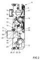
- FIG. 2 shows the arranged in the first wing 2 lock case 5 of the espagnolette lock 4 with a Locking device 11 and with adjacent region of the arranged in the second wing 3 actuator 8 FIG. 1 ,
- an espagnolette slide 12 is slidably guided.
- the latch 9 and the latch 10 are moved out of the lock case 5 and the espagnolette slide 12 is in a lower position. This characterizes the locking position of the espagnolette lock 4.
- the espagnolette 12 can be moved by means of a lock cylinder, of which only one cam 13 is shown for simplicity, and by turning a nut half 14 clockwise upwards.
- the bolt 9 is withdrawn into the lock case 5.
- the nut half 14 is connected via a coupling device 15 with a latch retracting lever 16.
- the case is biased by the force of a spring element 17 in the position shown from the lock case 5 out.
- the coupling of the movements of the bolt 9 with the espagnolette 12 has a arranged on the bolt 9 guide member 18 and disposed in the espagnolette 12 guide cam 19.
- the guide cam 19 has a direction of movement of the espagnolette 12 having guide portion 20 in which the guide member 18 of Riegel's 9 is held.
- the driver 13 of the lock cylinder drives a drive device 21 with a single drive arc 22 and a drive element 23 at.
- the drive arc 22 is coupled to the espagnolette 12, while the drive element 23 is supported on the latch retracting lever 16.
- the driver 13 facing stops 24, 25 of the drive element 23 and the drive arc 22 are sandwiched one above the other.
- the espagnolette 12 slides behind in the in FIG. 2 In this position, the latch 9 is supported by the espagnolette 12 and can not be pushed back. A protruding from the latch 9 control 28 is opposite to the operable by the handle 7 of the second wing 3 actuator 8.
- FIG. 3 shows that the connection sheet 22 is connected via a bearing 31 on the espagnolette 12 slide.
- a renewed driving of the drive means 21 by rotation of the driver 13 in a clockwise direction will cause only the case 10 is withdrawn, since the locking device 11 is already unlocked.
- the driver 13 pivoted counterclockwise the driver 13 comes against a second stop 29 of the drive arc 22.
- the locking device 11 in the in FIG. 2 shown locked position driven without the drive element 23 and thus the case 10 is driven.
- the second stop 29 has a distance from the first stop 24, which is required for pivoting the driver 13 in order to remove a key from the lock cylinder.
- FIG. 4 shows FIG. 4 in that the lock case 5 has a receptacle 30 for the use of a locking cylinder having the catch 13.
- the clockwise rotation of the follower indicates an unlocking direction while the counterclockwise turn indicates a locking direction of the follower.
- the components arranged in the lock case 5 are represented from one side, the intended inside of a room.
- the nut half to be arranged on the intended inside of a room has the function of the nut half 14 described above.
- the nut half to be arranged on the opposite side, the intended outside of the room is permanently coupled when using a doorknob on the outside of the door leaf, or it is used instead of two sandwiched one-half nut halves a one-piece nut.
Landscapes
- Engineering & Computer Science (AREA)
- Mechanical Engineering (AREA)
- Lock And Its Accessories (AREA)
Abstract
Description
- Die Erfindung betrifft ein Treibstangenschloss insbesondere für eine zweiflügelige Tür mit einer Riegeleinrichtung, mit einem aus einem Schlosskasten herausfahrbaren Riegel und einer federnd aus dem Schlosskasten vorgespannten und über einen Fallenrückzugshebel rückziehbaren Falle und einem quer zur Bewegung des Riegels verschieblichen Treibstangenanschlussschieber der Riegeleinrichtung, mit einer in dem Treibstangenanschlussschieber angeordneten Führungskurve und mit einem mit der Führungskurve gekoppelten Führungselement des Riegels, mit einer einen Antriebsbogen aufweisenden Antriebseinrichtung der Riegeleinrichtung, wobei der Antriebsbogen um eine Aufnahme für einen Schließzylinder in einem Kreisbogen verschieblich geführt ist und zu seiner Mitnahme im Bewegungsbereich eines Mitnehmers des Schließzylinders angeordnet ist, mit einem mit dem Fallenrückzugshebel gekoppelten und von der Antriebseinrichtung antreibbaren Antriebselement.
- Ein solches Schloss ist aus der
EP 1 743 994 A2 bekannt. Bei diesem Treibstangenschloss weist die Antriebseinrichtung zwei übereinander liegende Bogenstücke als Antriebsbögen auf. Das eine der Bogenstücke dient zur Übertragung einer Riegelvorschlussbewegung auf einen mit dem Riegel gekoppelten Schieber und das andere der Bogenstücke zur Übertragung einer Riegelrückschlussbewegung. Die Bogenstücke weisen Anschlagschultern und Gegenanschlagschultern auf, deren Abstände für einen Drehfreigang für den Schließzylinder bemessen sind. Ein von den Bogenstücken antreibbarer Hilfsschieber ist mit einer Nusshälfte gekoppelt. - Nachteilig bei dem bekannten Schloss ist, dass die beiden Bogenstücke aufwändig zu montieren sind und einen hohen Bauraum beanspruchen.
- Der Erfindung liegt das Problem zugrunde, ein Treibstangenschloss der eingangs genannten Art so weiter zu bilden, dass es möglichst einfach aufgebaut ist und einfach zu montieren ist.
- Dieses Problem wird erfindungsgemäß dadurch gelöst, dass das Antriebselement mit einem Anschlag sandwichartig über einem Anschlag des Antriebsbogens liegt und in den Bewegungsbereich des Mitnehmers des Schließzylinders eindringt, so dass beim Antrieb des Mitnehmers das Antriebselement und der Antriebsbogen antreibbar sind.
- Durch diese Gestaltung sind das Antriebselement und der Antriebsbogen von dem Mitnehmer des Schließzylinders zugänglich. Damit genügt zum Antrieb des Treibstangenanschlussschiebers und zum Fallenrückzug ein einziger Antriebsbogen. Hierdurch hat das erfindungsgemäße Treibstangenschloss besonders wenige zu montierende Bauteile und ist daher besonders einfach aufgebaut und lässt sich einfach montieren.
- Eine Beeinflussung der Bewegungen des Treibstangenanschlussschiebers und des Antriebselementes lässt sich gemäß einer vorteilhaften Weiterbildung der Erfindung vermeiden, wenn der Antriebsbogen ausschließlich mit dem Treibstangenanschlussschieber gekoppelt ist und wenn das Antriebselement und der Antriebsbogen bei einem Ausfahren der Falle sandwichartig übereinander gleitend geführt sind. Obwohl nur ein einzelner Antriebsbogen vorhanden ist und mit einer Schließbartbewegung Falle und Riegeleinrichtung angetrieben werden können, werden dank der Erfindung unerwünschte Beeinflussungen der Bewegungen der Bauteile vermieden. Eine Rückbewegung des Treibstangenanschlussschiebers durch die Rückbewegung des Antriebselementes wird damit zuverlässig vermieden. Die Riegeleinrichtung kann daher in der entriegelten Stellung verbleiben, wenn die Falle durch eine Federkraft ausgefahren wird.
- Das Treibstangenschloss gestaltet sich gemäß einer anderen vorteilhaften Weiterbildung der Erfindung konstruktiv besonders einfach, durch einen parallelen Antrieb des Antriebselementes zum Zurückziehen der Falle und des Antriebsbogens zum Entriegeln der Riegeleinrichtung durch Antrieb des Schließzylinders in eine Entriegelungsrichtung. Durch diese Gestaltung wird eine Drehrichtung des Schließzylinders definiert, in der die Riegelungseinrichtung und das Antriebselement parallel angetrieben werden.
- Zur weiteren Vereinfachung des konstruktiven Aufbaus des Treibstangenschlosses trägt es gemäß einer anderen vorteilhaften Weiterbildung bei durch ausschließlichen Antrieb des Antriebsbogens zum Verriegeln der Riegeleinrichtung durch Antrieb des Schließzylinders in eine Verriegelungsrichtung.
- Der bauliche Aufwand des Treibstangenschlosses lässt sich gemäß einer anderen vorteilhaften Weiterbildung der Erfindung besonders gering halten, wenn der Anschlussbogen über ein Drehlager mit dem Treibstangenanschlussschieber verbunden ist. Hierfür kann im einfachsten Fall der Treibstangenanschlussschieber einen hervorstehenden Dorn als Lagerachse aufweisen, so dass der Anschlussbogen mit einer Ausnehmung als Lagerbohrung einfach aufgesteckt werden kann.
- Die Erfindung lässt zahlreiche Ausführungsformen zu. Zur weiteren Verdeutlichung ihres Grundprinzips ist eine davon in der Zeichnung dargestellt und wird nachfolgend beschrieben. Diese zeigt in
- Fig. 1
- eine zweiflügelige Tür mit einem erfindungsgemäßen Treibstangenschloss,
- Fig. 2
- das Treibstangenschloss im verriegelten Zustand in einer vergrößerten Darstellung,
- Fig. 3
- einen vergrößerten Teilbereich des Treibstangenschlosses aus
Figur 2 beim Entriegeln, - Fig. 4
- einen vergrößerten Teilbereich des Treibstangenschlosses aus
Figur 2 im entriegelten Zustand nach einem federbetätigten Ausfahren einer Falle. -
Figur 1 zeigt eine zweiflügelige Tür mit einem Rahmen 1 und mit erstem Flügel 2 und mit einem zweiten Flügel 3. Die Flügel 2, 3 lassen sich über ein schematisch dargestelltes Treibstangenschloss 4 in dem Rahmen 1 verriegeln. Das Treibstangenschloss 4 hat einen in dem ersten Flügel 2 angeordneten Schlosskasten 5 und eine ebenfalls in dem ersten Flügel 2 angeordnete Handhabe 6. Der zweite Flügel 3 hat ebenfalls eine Handhabe 7 und eine von der Handhabe 7 ansteuerbare Betätigungseinrichtung 8. Die Betätigungseinrichtung 8 steht einem aus dem Schlosskasten 5 herausragenden Riegel 9 gegenüber. Weiterhin ragt aus dem Schlosskasten 5 eine Falle 10 heraus. -
Figur 2 zeigt den im ersten Flügel 2 angeordneten Schlosskasten 5 des Treibstangenschlosses 4 mit einer Riegeleinrichtung 11 und mit angrenzendem Bereich der im zweiten Flügel 3 angeordneten Betätigungseinrichtung 8 ausFigur 1 . In dem Schlosskasten 5 ist ein Treibstangenanschlussschieber 12 verschieblich geführt. Über den Treibstangenanschlussschieber 12 lassen sich weitere, nicht dargestellte Nebenschlösser außerhalb des dargestellten Schlosskastens 5 ansteuern. Der Riegel 9 und die Falle 10 sind aus dem Schlosskasten 5 herausgefahren und der Treibstangenanschlussschieber 12 befindet sich in einer unteren Position. Dies kennzeichnet die Verriegelungsstellung des Treibstangenschlosses 4. Der Treibstangenanschlussschieber 12 lässt sich mittels eines Schließzylinders, von dem vereinfachend nur ein Mitnehmer 13 dargestellt ist, und über ein Verdrehen einer Nusshälfte 14 im Uhrzeigersinn nach oben hin verschieben. Dabei wird auch der Riegel 9 in den Schlosskasten 5 zurückgezogen. Die Nusshälfte 14 ist über eine Koppeleinrichtung 15 mit einem Fallenrückzugshebel 16 verbunden. Die Falle ist mittels der Kraft eines Federelementes 17 in die dargestellte Lage aus dem Schlosskasten 5 heraus vorgespannt. Beim Antrieb des Fallenrückzugshebels 16 im Uhrzeigersinn wird die Falle 10 in den Schlosskasten 5 zurückgezogen und das Federelement 17 gespannt. Die Koppelung der Bewegungen des Riegels 9 mit dem Treibstangenanschlussschieber 12 hat ein auf dem Riegel 9 angeordnetes Führungselement 18 und eine in dem Treibstangenanschlussschieber 12 angeordnete Führungskurve 19. Die Führungskurve 19 hat einen in Bewegungsrichtung des Treibstangenanschlussschiebers 12 aufweisenden Führungsabschnitt 20, in der das Führungselement 18 des Riegels 9 gehalten ist. - Der Mitnehmer 13 des Schließzylinders treibt eine Antriebseinrichtung 21 mit einem einzigen Antriebsbogen 22 und einem Antriebselement 23 an. Der Antriebsbogen 22 ist mit dem Treibstangenanschlussschieber 12 gekoppelt, während sich das Antriebselement 23 an dem Fallenrückzugshebel 16 abstützt. Dem Mitnehmer 13 zugewandte Anschläge 24, 25 des Antriebselementes 23 und des Antriebsbogens 22 liegen sandwichartig übereinander.
- Der Treibstangenanschlussschieber 12 hintergreift in der in
Figur 2 dargestellten Stellung mit einem Vorsprung 26 eine Schulter 27 des Riegels 9. In dieser Stellung ist der Riegel 9 von dem Treibstangenanschlussschieber 12 abgestützt und kann nicht zurückgedrückt werden kann. Ein aus dem Riegel 9 hervor ragendes Steuerelement 28 steht der von der Handhabe 7 des zweiten Flügels 3 antreibbaren Betätigungseinrichtung 8 gegenüber. - Wenn man ausgehend von der Stellung aus
Figur 2 den Mitnehmer 13 im Uhrzeigersinn verdreht, gelangt man in die inFigur 3 dargestellte entriegelte Stellung des Treibstangenschlosses 4. Durch den Antrieb der Antriebseinrichtung 21 über den Mitnehmer 13 im Uhrzeigersinn wird zum einen der Antriebsbogen 22 verschwenkt und die Riegeleinrichtung 11 angesteuert. Durch die Ansteuerung der Riegeleinrichtung 11 wird der Treibstangenanschlussschieber 12 nach oben verschoben und damit der Riegel 9 in den Schlosskasten 5 zurückgezogen. Zum anderen wird bei der Verdrehung des Mitnehmers 13 im Uhrzeigersinn die Falle 10 in den Schlosskasten 5 zurückgezogen und dabei das Federelement 17 gespannt.Figur 3 zeigt zudem, dass der Anschlussbogen 22 über eine Lagerung 31 an dem Treibstangenanschlussschieber 12 angebunden ist. - Wenn man ausgehend von der entriegelten Stellung aus Figur 3 den Mitnehmer 13 geringfügig gegen den Uhrzeigersinn zurückdreht oder loslässt, drückt das Federelement 17 aus
Figur 2 die Falle 10 wieder aus dem Schlosskasten 5 heraus. Dabei wird der Fallenrückzugshebel 16 zurückgeschwenkt und treibt das Antriebselement 23 an, wie es inFigur 4 dargestellt ist. Der Treibstangenanschlussschieber 12 verbleibt jedoch in seiner Lage. Damit sind die Anschläge 24, 25 des Antriebsbogens 22 und des Antriebselementes 23 zueinander versetzt. - Ein erneutes Antreiben der Antriebseinrichtung 21 durch Drehung des Mitnehmers 13 im Uhrzeigersinn wird dazu führen, dass nur die Falle 10 zurückgezogen wird, da die Riegeleinrichtung 11 bereits entriegelt ist. Wird jedoch ausgehend von der Stellung aus
Figur 4 der Mitnehmer 13 gegen den Uhrzeigersinn verschwenkt, gelangt der Mitnehmer 13 gegen einen zweiten Anschlag 29 des Antriebsbogens 22. In diesem Fall wird die Riegeleinrichtung 11 in die inFigur 2 dargestellte verriegelte Stellung angetrieben, ohne dass das Antriebselement 23 und damit die Falle 10 angetrieben wird. Der zweite Anschlag 29 hat von dem ersten Anschlag 24 einen Abstand, welcher zum Verschwenken des Mitnehmers 13 erforderlich ist, um einen Schlüssel von dem Schließzylinder abzuziehen. Weiterhin zeigtFigur 4 , dass der Schlosskasten 5 eine Aufnahme 30 zum Einsatz eines den Mitnehmer 13 aufweisenden Schließzylinders hat. - Die Drehung des Mitnehmers im Uhrzeigersinn kennzeichnet damit eine Entriegelungsrichtung, während die Drehung gegen den Uhrzeigersinn eine Verriegelungsrichtung des Mitnehmers kennzeichnet.
- Die im Schlosskasten 5 angeordneten Bauteile sind von einer Seite, der vorgesehenen Innenseite eines Raums, dargestellt. In der Regel weisen solche Treibstangenschlösser 4 für Fluchttüren oder für Paniktüren zwei sandwichartig übereinander liegende Nusshälften auf. Die an der vorgesehenen Innenseite eines Raums anzuordnende Nusshälfte hat die Funktion wie die oben beschriebene Nusshälfte 14. Die an der gegenüberliegenden Seite, der vorgesehenen Außenseite des Raums, anzuordnende Nusshälfte ist, bei einer Verwendung eines Türknaufs an der Außenseite des Türflügels, permanent eingekoppelt oder es wird statt zweier sandwichartig übereinander liegender Nusshälften eine einteilige Nuss verwendet.
Claims (5)
- Treibstangenschloss (4) insbesondere für eine zweiflügelige Tür mit einer Riegeleinrichtung (11), mit einem aus einem Schlosskasten (5) herausfahrbaren Riegel (9) und einer federnd aus dem Schlosskasten (5) vorgespannten und über einen Fallenrückzugshebel (16) rückziehbaren Falle (10) und einem quer zur Bewegung des Riegels (9) verschieblichen Treibstangenanschlussschieber (12) der Riegeleinrichtung (11), mit einer in dem Treibstangenanschlussschieber (12) angeordneten Führungskurve (19) und mit einem mit der Führungskurve (19) gekoppelten Führungselement (18) des Riegels (9), mit einer einen Antriebsbogen (22) aufweisenden Antriebseinrichtung (21) der Riegeleinrichtung (11), wobei der Antriebsbogen (22) um eine Aufnahme (30) für einen Schließzylinder in einem Kreisbogen verschieblich geführt ist und zu seiner Mitnahme im Bewegungsbereich eines Mitnehmers (13) des Schließzylinders angeordnet ist, mit einem mit dem Fallenrückzugshebel (16) gekoppelten und von der Antriebseinrichtung (21) antreibbaren Antriebselement (23), dadurch gekennzeichnet, dass das Antriebselement (23) mit einem Anschlag (25) sandwichartig über einem Anschlag (24) des Antriebsbogens (22) liegt und in den Bewegungsbereich des Mitnehmers (13) des Schließzylinders eindringt, so dass beim Antrieb des Mitnehmers (13) das Antriebselement (23) und der Antriebsbogen (22) antreibbar sind.
- Treibstangenschloss nach Anspruch 1, dadurch gekennzeichnet, dass der Antriebsbogen (22) ausschließlich mit dem Treibstangenanschlussschieber (12) gekoppelt ist und dass das Antriebselement (23) und der Antriebsbogen (22) bei einem Ausfahren der Falle (10) sandwichartig übereinander gleitend geführt sind.
- Treibstangenschloss nach Anspruch 1 oder 2, gekennzeichnet durch einen parallelen Antrieb des Antriebselementes (23) zum Zurückziehen der Falle (10) und des Antriebsbogens (22) zum Entriegeln der Riegeleinrichtung (11) durch Antrieb des Schließzylinders in eine Entriegelungsrichtung.
- Treibstangenschloss nach einem der vorhergehenden Ansprüche, gekennzeichnet durch ausschließlichen Antrieb des Antriebsbogens (22) zum Verriegeln der Riegeleinrichtung (11) durch Antrieb des Schließzylinders in eine Verriegelungsrichtung.
- Treibstangenschloss nach einem der vorhergehenden Ansprüche, dadurch gekennzeichnet, dass der Anschlussbogen (22) über ein Drehlager (31) mit dem Treibstangenanschlussschieber (12) verbunden ist.
Priority Applications (1)
| Application Number | Priority Date | Filing Date | Title |
|---|---|---|---|
| PL15174867T PL3029233T3 (pl) | 2014-08-01 | 2015-07-01 | Zamek zasuwnicowy |
Applications Claiming Priority (1)
| Application Number | Priority Date | Filing Date | Title |
|---|---|---|---|
| DE102014215176.7A DE102014215176A1 (de) | 2014-08-01 | 2014-08-01 | Treibstangenschloss |
Publications (2)
| Publication Number | Publication Date |
|---|---|
| EP3029233A1 true EP3029233A1 (de) | 2016-06-08 |
| EP3029233B1 EP3029233B1 (de) | 2018-11-14 |
Family
ID=53514023
Family Applications (1)
| Application Number | Title | Priority Date | Filing Date |
|---|---|---|---|
| EP15174867.0A Active EP3029233B1 (de) | 2014-08-01 | 2015-07-01 | Treibstangenschloss |
Country Status (3)
| Country | Link |
|---|---|
| EP (1) | EP3029233B1 (de) |
| DE (1) | DE102014215176A1 (de) |
| PL (1) | PL3029233T3 (de) |
Families Citing this family (1)
| Publication number | Priority date | Publication date | Assignee | Title |
|---|---|---|---|---|
| DE102017222660A1 (de) * | 2017-12-13 | 2019-06-13 | Aug. Winkhaus Gmbh & Co. Kg | Schloss |
Citations (4)
| Publication number | Priority date | Publication date | Assignee | Title |
|---|---|---|---|---|
| EP0454959A2 (de) * | 1990-05-02 | 1991-11-06 | Carl Fuhr GmbH & Co. | Schliesszylinderbetätigbares Treibstangenschloss |
| DE29909660U1 (de) * | 1999-06-02 | 1999-08-05 | Gretsch-Unitas GmbH Baubeschläge, 71254 Ditzingen | Türverschluß |
| EP1743994A2 (de) | 2005-07-14 | 2007-01-17 | KFV Karl Fliether GmbH & Co. KG | Fluchttürschloss |
| DE202013000921U1 (de) * | 2013-01-30 | 2013-02-20 | Kfv Karl Fliether Gmbh & Co. Kg | Panikschloss |
-
2014
- 2014-08-01 DE DE102014215176.7A patent/DE102014215176A1/de not_active Withdrawn
-
2015
- 2015-07-01 PL PL15174867T patent/PL3029233T3/pl unknown
- 2015-07-01 EP EP15174867.0A patent/EP3029233B1/de active Active
Patent Citations (4)
| Publication number | Priority date | Publication date | Assignee | Title |
|---|---|---|---|---|
| EP0454959A2 (de) * | 1990-05-02 | 1991-11-06 | Carl Fuhr GmbH & Co. | Schliesszylinderbetätigbares Treibstangenschloss |
| DE29909660U1 (de) * | 1999-06-02 | 1999-08-05 | Gretsch-Unitas GmbH Baubeschläge, 71254 Ditzingen | Türverschluß |
| EP1743994A2 (de) | 2005-07-14 | 2007-01-17 | KFV Karl Fliether GmbH & Co. KG | Fluchttürschloss |
| DE202013000921U1 (de) * | 2013-01-30 | 2013-02-20 | Kfv Karl Fliether Gmbh & Co. Kg | Panikschloss |
Also Published As
| Publication number | Publication date |
|---|---|
| EP3029233B1 (de) | 2018-11-14 |
| DE102014215176A1 (de) | 2016-02-04 |
| PL3029233T3 (pl) | 2019-03-29 |
Similar Documents
| Publication | Publication Date | Title |
|---|---|---|
| DE202013000921U1 (de) | Panikschloss | |
| DE102016108706A1 (de) | Standflügelschloss mit Motorantrieb | |
| DE102012001787A1 (de) | Türöffner und Tür mit Türöffner | |
| EP2339096B1 (de) | Treibstangenschloss mit Panikfunktion und Mehrfachverriegelung | |
| EP2634330B1 (de) | Automatikschloss | |
| EP2980340B1 (de) | Treibstangenschloss | |
| EP3091151B1 (de) | Treibstangensperre für einen treibstangenbeschlag | |
| EP3144455B1 (de) | Verriegelungseinrichtung | |
| EP3018274B1 (de) | Gegenschloss eines treibstangenschlosses einer zweiflügeligen tür | |
| EP3029233B1 (de) | Treibstangenschloss | |
| DE202011103191U1 (de) | Selbstverriegelndes Schloss | |
| DE4431925C2 (de) | Schloß für Gefängnistüren | |
| EP2634333A2 (de) | Schloss | |
| EP2808468B1 (de) | Verriegelungseinheit für eine Schließanlage | |
| EP3498942B1 (de) | Schloss | |
| EP3655601B1 (de) | Schloss | |
| EP2708686B1 (de) | Panikschloss und Verfahren zum Betrieb eines Panikschlosses | |
| DE102015115830A1 (de) | Tageshebel | |
| EP2388420A2 (de) | Treibstangenbetätigbares Schloss mit mehreren Riegelgliedern | |
| EP2998494B1 (de) | Treibstangenschloss | |
| EP2634331B1 (de) | Automatikschloss | |
| EP3498943B1 (de) | Schloss | |
| EP2987929B1 (de) | Treibstangenschloss | |
| EP3315695A1 (de) | Schloss | |
| DE202012104831U1 (de) | Schloss für eine Tür oder ein Fenster |
Legal Events
| Date | Code | Title | Description |
|---|---|---|---|
| PUAI | Public reference made under article 153(3) epc to a published international application that has entered the european phase |
Free format text: ORIGINAL CODE: 0009012 |
|
| AK | Designated contracting states |
Kind code of ref document: A1 Designated state(s): AL AT BE BG CH CY CZ DE DK EE ES FI FR GB GR HR HU IE IS IT LI LT LU LV MC MK MT NL NO PL PT RO RS SE SI SK SM TR |
|
| AX | Request for extension of the european patent |
Extension state: BA ME |
|
| STAA | Information on the status of an ep patent application or granted ep patent |
Free format text: STATUS: REQUEST FOR EXAMINATION WAS MADE |
|
| 17P | Request for examination filed |
Effective date: 20161026 |
|
| RBV | Designated contracting states (corrected) |
Designated state(s): AL AT BE BG CH CY CZ DE DK EE ES FI FR GB GR HR HU IE IS IT LI LT LU LV MC MK MT NL NO PL PT RO RS SE SI SK SM TR |
|
| GRAP | Despatch of communication of intention to grant a patent |
Free format text: ORIGINAL CODE: EPIDOSNIGR1 |
|
| STAA | Information on the status of an ep patent application or granted ep patent |
Free format text: STATUS: GRANT OF PATENT IS INTENDED |
|
| RIC1 | Information provided on ipc code assigned before grant |
Ipc: E05C 9/02 20060101AFI20180612BHEP Ipc: E05B 17/04 20060101ALI20180612BHEP |
|
| INTG | Intention to grant announced |
Effective date: 20180702 |
|
| GRAS | Grant fee paid |
Free format text: ORIGINAL CODE: EPIDOSNIGR3 |
|
| GRAA | (expected) grant |
Free format text: ORIGINAL CODE: 0009210 |
|
| STAA | Information on the status of an ep patent application or granted ep patent |
Free format text: STATUS: THE PATENT HAS BEEN GRANTED |
|
| AK | Designated contracting states |
Kind code of ref document: B1 Designated state(s): AL AT BE BG CH CY CZ DE DK EE ES FI FR GB GR HR HU IE IS IT LI LT LU LV MC MK MT NL NO PL PT RO RS SE SI SK SM TR |
|
| REG | Reference to a national code |
Ref country code: CH Ref legal event code: EP Ref country code: AT Ref legal event code: REF Ref document number: 1065015 Country of ref document: AT Kind code of ref document: T Effective date: 20181115 |
|
| REG | Reference to a national code |
Ref country code: IE Ref legal event code: FG4D Free format text: LANGUAGE OF EP DOCUMENT: GERMAN |
|
| REG | Reference to a national code |
Ref country code: DE Ref legal event code: R096 Ref document number: 502015006835 Country of ref document: DE |
|
| REG | Reference to a national code |
Ref country code: NL Ref legal event code: FP |
|
| REG | Reference to a national code |
Ref country code: LT Ref legal event code: MG4D |
|
| PG25 | Lapsed in a contracting state [announced via postgrant information from national office to epo] |
Ref country code: HR Free format text: LAPSE BECAUSE OF FAILURE TO SUBMIT A TRANSLATION OF THE DESCRIPTION OR TO PAY THE FEE WITHIN THE PRESCRIBED TIME-LIMIT Effective date: 20181114 Ref country code: LT Free format text: LAPSE BECAUSE OF FAILURE TO SUBMIT A TRANSLATION OF THE DESCRIPTION OR TO PAY THE FEE WITHIN THE PRESCRIBED TIME-LIMIT Effective date: 20181114 Ref country code: LV Free format text: LAPSE BECAUSE OF FAILURE TO SUBMIT A TRANSLATION OF THE DESCRIPTION OR TO PAY THE FEE WITHIN THE PRESCRIBED TIME-LIMIT Effective date: 20181114 Ref country code: NO Free format text: LAPSE BECAUSE OF FAILURE TO SUBMIT A TRANSLATION OF THE DESCRIPTION OR TO PAY THE FEE WITHIN THE PRESCRIBED TIME-LIMIT Effective date: 20190214 Ref country code: ES Free format text: LAPSE BECAUSE OF FAILURE TO SUBMIT A TRANSLATION OF THE DESCRIPTION OR TO PAY THE FEE WITHIN THE PRESCRIBED TIME-LIMIT Effective date: 20181114 Ref country code: BG Free format text: LAPSE BECAUSE OF FAILURE TO SUBMIT A TRANSLATION OF THE DESCRIPTION OR TO PAY THE FEE WITHIN THE PRESCRIBED TIME-LIMIT Effective date: 20190214 Ref country code: IS Free format text: LAPSE BECAUSE OF FAILURE TO SUBMIT A TRANSLATION OF THE DESCRIPTION OR TO PAY THE FEE WITHIN THE PRESCRIBED TIME-LIMIT Effective date: 20190314 Ref country code: FI Free format text: LAPSE BECAUSE OF FAILURE TO SUBMIT A TRANSLATION OF THE DESCRIPTION OR TO PAY THE FEE WITHIN THE PRESCRIBED TIME-LIMIT Effective date: 20181114 |
|
| PG25 | Lapsed in a contracting state [announced via postgrant information from national office to epo] |
Ref country code: RS Free format text: LAPSE BECAUSE OF FAILURE TO SUBMIT A TRANSLATION OF THE DESCRIPTION OR TO PAY THE FEE WITHIN THE PRESCRIBED TIME-LIMIT Effective date: 20181114 Ref country code: GR Free format text: LAPSE BECAUSE OF FAILURE TO SUBMIT A TRANSLATION OF THE DESCRIPTION OR TO PAY THE FEE WITHIN THE PRESCRIBED TIME-LIMIT Effective date: 20190215 Ref country code: SE Free format text: LAPSE BECAUSE OF FAILURE TO SUBMIT A TRANSLATION OF THE DESCRIPTION OR TO PAY THE FEE WITHIN THE PRESCRIBED TIME-LIMIT Effective date: 20181114 Ref country code: AL Free format text: LAPSE BECAUSE OF FAILURE TO SUBMIT A TRANSLATION OF THE DESCRIPTION OR TO PAY THE FEE WITHIN THE PRESCRIBED TIME-LIMIT Effective date: 20181114 Ref country code: PT Free format text: LAPSE BECAUSE OF FAILURE TO SUBMIT A TRANSLATION OF THE DESCRIPTION OR TO PAY THE FEE WITHIN THE PRESCRIBED TIME-LIMIT Effective date: 20190314 |
|
| PG25 | Lapsed in a contracting state [announced via postgrant information from national office to epo] |
Ref country code: DK Free format text: LAPSE BECAUSE OF FAILURE TO SUBMIT A TRANSLATION OF THE DESCRIPTION OR TO PAY THE FEE WITHIN THE PRESCRIBED TIME-LIMIT Effective date: 20181114 Ref country code: IT Free format text: LAPSE BECAUSE OF FAILURE TO SUBMIT A TRANSLATION OF THE DESCRIPTION OR TO PAY THE FEE WITHIN THE PRESCRIBED TIME-LIMIT Effective date: 20181114 Ref country code: CZ Free format text: LAPSE BECAUSE OF FAILURE TO SUBMIT A TRANSLATION OF THE DESCRIPTION OR TO PAY THE FEE WITHIN THE PRESCRIBED TIME-LIMIT Effective date: 20181114 |
|
| REG | Reference to a national code |
Ref country code: DE Ref legal event code: R097 Ref document number: 502015006835 Country of ref document: DE |
|
| PG25 | Lapsed in a contracting state [announced via postgrant information from national office to epo] |
Ref country code: SK Free format text: LAPSE BECAUSE OF FAILURE TO SUBMIT A TRANSLATION OF THE DESCRIPTION OR TO PAY THE FEE WITHIN THE PRESCRIBED TIME-LIMIT Effective date: 20181114 Ref country code: SM Free format text: LAPSE BECAUSE OF FAILURE TO SUBMIT A TRANSLATION OF THE DESCRIPTION OR TO PAY THE FEE WITHIN THE PRESCRIBED TIME-LIMIT Effective date: 20181114 Ref country code: RO Free format text: LAPSE BECAUSE OF FAILURE TO SUBMIT A TRANSLATION OF THE DESCRIPTION OR TO PAY THE FEE WITHIN THE PRESCRIBED TIME-LIMIT Effective date: 20181114 Ref country code: EE Free format text: LAPSE BECAUSE OF FAILURE TO SUBMIT A TRANSLATION OF THE DESCRIPTION OR TO PAY THE FEE WITHIN THE PRESCRIBED TIME-LIMIT Effective date: 20181114 |
|
| PLBE | No opposition filed within time limit |
Free format text: ORIGINAL CODE: 0009261 |
|
| STAA | Information on the status of an ep patent application or granted ep patent |
Free format text: STATUS: NO OPPOSITION FILED WITHIN TIME LIMIT |
|
| 26N | No opposition filed |
Effective date: 20190815 |
|
| PG25 | Lapsed in a contracting state [announced via postgrant information from national office to epo] |
Ref country code: SI Free format text: LAPSE BECAUSE OF FAILURE TO SUBMIT A TRANSLATION OF THE DESCRIPTION OR TO PAY THE FEE WITHIN THE PRESCRIBED TIME-LIMIT Effective date: 20181114 |
|
| PG25 | Lapsed in a contracting state [announced via postgrant information from national office to epo] |
Ref country code: MC Free format text: LAPSE BECAUSE OF FAILURE TO SUBMIT A TRANSLATION OF THE DESCRIPTION OR TO PAY THE FEE WITHIN THE PRESCRIBED TIME-LIMIT Effective date: 20181114 |
|
| REG | Reference to a national code |
Ref country code: CH Ref legal event code: PL |
|
| PG25 | Lapsed in a contracting state [announced via postgrant information from national office to epo] |
Ref country code: TR Free format text: LAPSE BECAUSE OF FAILURE TO SUBMIT A TRANSLATION OF THE DESCRIPTION OR TO PAY THE FEE WITHIN THE PRESCRIBED TIME-LIMIT Effective date: 20181114 |
|
| REG | Reference to a national code |
Ref country code: BE Ref legal event code: MM Effective date: 20190731 |
|
| PG25 | Lapsed in a contracting state [announced via postgrant information from national office to epo] |
Ref country code: LI Free format text: LAPSE BECAUSE OF NON-PAYMENT OF DUE FEES Effective date: 20190731 Ref country code: CH Free format text: LAPSE BECAUSE OF NON-PAYMENT OF DUE FEES Effective date: 20190731 Ref country code: BE Free format text: LAPSE BECAUSE OF NON-PAYMENT OF DUE FEES Effective date: 20190731 Ref country code: LU Free format text: LAPSE BECAUSE OF NON-PAYMENT OF DUE FEES Effective date: 20190701 |
|
| PG25 | Lapsed in a contracting state [announced via postgrant information from national office to epo] |
Ref country code: IE Free format text: LAPSE BECAUSE OF NON-PAYMENT OF DUE FEES Effective date: 20190701 |
|
| PG25 | Lapsed in a contracting state [announced via postgrant information from national office to epo] |
Ref country code: CY Free format text: LAPSE BECAUSE OF FAILURE TO SUBMIT A TRANSLATION OF THE DESCRIPTION OR TO PAY THE FEE WITHIN THE PRESCRIBED TIME-LIMIT Effective date: 20181114 |
|
| PG25 | Lapsed in a contracting state [announced via postgrant information from national office to epo] |
Ref country code: MT Free format text: LAPSE BECAUSE OF FAILURE TO SUBMIT A TRANSLATION OF THE DESCRIPTION OR TO PAY THE FEE WITHIN THE PRESCRIBED TIME-LIMIT Effective date: 20181114 Ref country code: HU Free format text: LAPSE BECAUSE OF FAILURE TO SUBMIT A TRANSLATION OF THE DESCRIPTION OR TO PAY THE FEE WITHIN THE PRESCRIBED TIME-LIMIT; INVALID AB INITIO Effective date: 20150701 |
|
| PG25 | Lapsed in a contracting state [announced via postgrant information from national office to epo] |
Ref country code: MK Free format text: LAPSE BECAUSE OF FAILURE TO SUBMIT A TRANSLATION OF THE DESCRIPTION OR TO PAY THE FEE WITHIN THE PRESCRIBED TIME-LIMIT Effective date: 20181114 |
|
| P01 | Opt-out of the competence of the unified patent court (upc) registered |
Effective date: 20230512 |
|
| REG | Reference to a national code |
Ref country code: DE Ref legal event code: R081 Ref document number: 502015006835 Country of ref document: DE Owner name: AUG. WINKHAUS SE & CO. KG, DE Free format text: FORMER OWNER: AUG. WINKHAUS GMBH & CO. KG, 48291 TELGTE, DE Ref country code: DE Ref legal event code: R081 Ref document number: 502015006835 Country of ref document: DE Owner name: AUG. WINKHAUS SE, DE Free format text: FORMER OWNER: AUG. WINKHAUS GMBH & CO. KG, 48291 TELGTE, DE |
|
| PGFP | Annual fee paid to national office [announced via postgrant information from national office to epo] |
Ref country code: NL Payment date: 20250723 Year of fee payment: 11 |
|
| REG | Reference to a national code |
Ref country code: DE Ref legal event code: R081 Ref document number: 502015006835 Country of ref document: DE Owner name: AUG. WINKHAUS SE, DE Free format text: FORMER OWNER: AUG. WINKHAUS SE & CO. KG, 48291 TELGTE, DE |
|
| PGFP | Annual fee paid to national office [announced via postgrant information from national office to epo] |
Ref country code: DE Payment date: 20250722 Year of fee payment: 11 |
|
| PGFP | Annual fee paid to national office [announced via postgrant information from national office to epo] |
Ref country code: GB Payment date: 20250724 Year of fee payment: 11 |
|
| PGFP | Annual fee paid to national office [announced via postgrant information from national office to epo] |
Ref country code: AT Payment date: 20250721 Year of fee payment: 11 Ref country code: FR Payment date: 20250723 Year of fee payment: 11 |
|
| PGFP | Annual fee paid to national office [announced via postgrant information from national office to epo] |
Ref country code: PL Payment date: 20260622 Year of fee payment: 12 |