EP2987929B1 - Treibstangenschloss - Google Patents
Treibstangenschloss Download PDFInfo
- Publication number
- EP2987929B1 EP2987929B1 EP15174862.1A EP15174862A EP2987929B1 EP 2987929 B1 EP2987929 B1 EP 2987929B1 EP 15174862 A EP15174862 A EP 15174862A EP 2987929 B1 EP2987929 B1 EP 2987929B1
- Authority
- EP
- European Patent Office
- Prior art keywords
- espagnolette
- lock
- bolt
- connecting slide
- support
- Prior art date
- Legal status (The legal status is an assumption and is not a legal conclusion. Google has not performed a legal analysis and makes no representation as to the accuracy of the status listed.)
- Active
Links
- 230000000903 blocking effect Effects 0.000 description 7
- 238000005452 bending Methods 0.000 description 2
- 230000003313 weakening effect Effects 0.000 description 2
- 239000011324 bead Substances 0.000 description 1
- 230000008878 coupling Effects 0.000 description 1
- 238000010168 coupling process Methods 0.000 description 1
- 238000005859 coupling reaction Methods 0.000 description 1
- 230000000994 depressogenic effect Effects 0.000 description 1
- 238000006073 displacement reaction Methods 0.000 description 1
- 238000004519 manufacturing process Methods 0.000 description 1
- 239000002184 metal Substances 0.000 description 1
Images

Classifications
-
- E—FIXED CONSTRUCTIONS
- E05—LOCKS; KEYS; WINDOW OR DOOR FITTINGS; SAFES
- E05C—BOLTS OR FASTENING DEVICES FOR WINGS, SPECIALLY FOR DOORS OR WINDOWS
- E05C9/00—Arrangements of simultaneously actuated bolts or other securing devices at well-separated positions on the same wing
- E05C9/02—Arrangements of simultaneously actuated bolts or other securing devices at well-separated positions on the same wing with one sliding bar for fastening when moved in one direction and unfastening when moved in opposite direction; with two sliding bars moved in the same direction when fastening or unfastening
- E05C9/026—Arrangements of simultaneously actuated bolts or other securing devices at well-separated positions on the same wing with one sliding bar for fastening when moved in one direction and unfastening when moved in opposite direction; with two sliding bars moved in the same direction when fastening or unfastening comprising key-operated locks, e.g. a lock cylinder to drive auxiliary deadbolts or latch bolts
-
- E—FIXED CONSTRUCTIONS
- E05—LOCKS; KEYS; WINDOW OR DOOR FITTINGS; SAFES
- E05B—LOCKS; ACCESSORIES THEREFOR; HANDCUFFS
- E05B17/00—Accessories in connection with locks
- E05B17/20—Means independent of the locking mechanism for preventing unauthorised opening, e.g. for securing the bolt in the fastening position
Definitions
- the invention relates to an espagnolette lock in particular for a two-leaf door with a locking device, with a displaceable from a lock case bolt of the locking device, and with a transversely movable to the movement of the bolt espagnolette slide of the locking device, with a arranged in the espagnolette slide guide curve and one with the guide curve coupled guide element of the bolt, wherein in a blocking position of the locking device, the guide element is arranged in a direction of movement of the espagnolette slide guide portion of the guide curve, with a movable between the blocking position and a release position, arranged on the espagnolette slide projection of the locking device, wherein the projection in the blocking position the latch is supported on a shoulder and pushed out in the release position from the range of movement of the shoulder t, and with a control ramp disposed in the latch for moving the projection out of the range of motion of the shoulder.
- Such espagnolette lock is for example from the DE 20 2013 000 920 U1 known.
- the lock case with the locking device is arranged in a wing of the two-leaf door and can be controlled via the control ramp from a second wing.
- Such espagnolette locks are arranged in so-called escape doors or panic doors and can be unlocked from both wings via a handle.
- In blocking position of Locking device is supported by the bolt on the shoulder on the projection and on the guide member in the guide portion of the guide cam on the espagnolette slide.
- In a violent Entriegelungs In a violent Entriegelungs needle high forces are often introduced into the bar. This may cause the espagnolette slide to bend. Subsequently, the espagnolette lock is usually destroyed and can not be unlocked with a key or by hand.
- the invention is based on the problem of further developing an espagnolette lock of the type mentioned at the outset so that loads of the espagnolette gate valve are kept as low as possible in the event of an unlocking attempt.
- the espagnolette gate valve has a support that the support is supported in the blocking position against a stop of the lock case and is moved out of the range of movement of the bolt in the release position.
- the number of components of the espagnolette lock can be kept particularly low according to another advantageous embodiment of the invention, when the support of the Espagnolette is designed as a bend. Furthermore, the support thereby has a particularly high stability, since the espagnolette usually made of sheet metal connecting slide is stiffened by the angling. The bending is preferably carried out from the edge of the espagnolette slide, so that a weakening of the espagnolette by the generation of the bend is avoided. Such bends on sheets fulfill the function of stiffening beads.
- the stop of the lock case could be, for example, an angling of the lock case.
- the espagnolette slide is guided in a central region through the lock case, such an angling would lead to a weakening of the lock case.
- Bending moments in the introduction of forces from the espagnolette in the lock case can be kept particularly low according to another advantageous embodiment of the invention, when the stop element is arranged in a near the espagnolette lock bottom.
- the manufacturing cost of the espagnolette lock can be according to another advantageous embodiment of Keep the invention particularly low when the stop element is formed as in the lock bottom and / or in the lock cover of the lock case pressed or screwed pin.
- the dimensions of the espagnolette lock can be kept particularly low according to another advantageous embodiment of the invention, when the bolt is designed with its projecting into the lock case end tapered by a slope and when the support supports the bolt in the blocking position immediately adjacent to the slope.
- FIG. 1 shows a two-leaf door with a frame 1 and with the first wing 2 and a second wing 3.
- the wings 2, 3 can be a schematically represented Lock espagnolette lock 4 in the frame 1.
- the espagnolette lock 4 has a arranged in the first wing 2 lock case 5 and also arranged in the first wing 2 handle 6.
- the second wing 3 also has a handle 7 and a controllable from the handle 7 actuator 8.
- the actuator 8 is one the lock case 5 outstanding latch 9 opposite. Furthermore, a trap 10 projects out of the lock case 5.
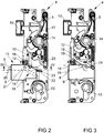
- FIG. 2 shows the arranged in the first wing 2 lock case 5 of the espagnolette lock 4 with a locking device 11 and with adjacent region of the arranged in the second wing 3 actuator 8 from FIG. 1 ,
- an espagnolette slide 12 is slidably guided.
- the latch 9 and the latch 10 are moved out of the lock case 5 and the espagnolette slide 12 is in a lower position.
- the espagnolette 12 can be moved by means of a lock cylinder, of which only one driver 13 is shown for simplicity, and by turning a nut 14 clockwise upwards. In this case, the bolt 9 is withdrawn into the lock case 5.
- the coupling of the movements of the bolt 9 with the espagnolette 12 has a guide element 15 arranged on the latch 9 and a guide cam 16 arranged in the espagnolette 12.
- the case 10 When driving the espagnolette 12 via the driver 13 of the lock cylinder also the case 10 is retracted into the lock case 5 via a change lever, not shown. Similarly, the case 10 via a latch retracting lever 17 in the Lock case 5 retracted when nut 14 is turned clockwise. The nut 14 is coupled to the handle 6 of the first wing 2, so that it is rotated clockwise when the handle 6 is depressed or pressed against the wing 2.
- the espagnolette 12 slides behind in the in FIG. 2 This indicates a blocking position in which the bolt 9 is supported by the espagnolette 12 and can not be pushed back from this position.
- a protruding from the latch 9 control element 20 is opposite to the operable by the handle 7 of the second wing 3 actuator 8.
- the guide element 15 is in a parallel to the espagnolette 12 arranged guide portion 21 of the guide cam 16. As a result, the return movement of the bolt 9 is also blocked.
- a support 22 is arranged, which supports the latch 9 and is itself supported by a stop 23 in the lock case 5.
- the support 22 supports the latch 9 near a slope 29 from.
- FIG. 3 illustrated unlocked position of the espagnolette lock 4.
- FIG. 3 shows FIG. 3 in that a control ramp 24 which is movable by the control element 20 is arranged behind the shoulder 19 of the bolt 9.
- the control ramp 24 presses from the position in FIG FIG. 2 the projection 18 from the range of movement of the shoulder 19 of the Tie 9 out.
- the projection 18 is located in the in FIG. 3 shown position in a release position in which the movement of the bolt 9 is released into the lock case 5 inside.
- the components arranged in the lock case 5 are represented from one side, the intended inside of a room.
- Such espagnolette locks 4 for escape doors or for panic doors on two sandwiched nut halves have the function of the nut 14 described above.
- the nut half to be arranged on the opposite side, the intended outside of the room, can be coupled in or, if a door knob is used, permanently coupled.
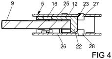
- FIG. 4 shows a sectional view of the espagnolette 4 from FIG. 2 In a sectional view along the line II - II.
- the lock case 5 has a the drive rod connecting slide 12 near the lock bottom 25 and a parallel thereto opposite the lock cover 26.
- the support 22 is formed as an angling of the espagnolette 12 and projects beyond the latch 9.
- the stop 23, are introduced via the forces of the latch 9 via the support 22 in the lock case 5, has a first, arranged in the lock bottom 25 stop element 27 and a second, arranged in the lock cover stop element 28.
- the stop elements 27, 28 are formed as screwed or pressed into the lock bottom 25 and the lock cover 26 pins. Furthermore, the stop elements 27, 28 at a distance from one another, so that the bolt 9 in the in FIG. 3 shown unlocked position between the stop elements 27, 28 can be moved through.
Landscapes
- Engineering & Computer Science (AREA)
- Mechanical Engineering (AREA)
- Lock And Its Accessories (AREA)
- Gates (AREA)
Description
- Die Erfindung betrifft ein Treibstangenschloss insbesondere für eine zweiflügelige Tür mit einer Riegeleinrichtung, mit einem aus einem Schlosskasten herausfahrbaren Riegel der Riegeleinrichtung, und mit einem quer zur Bewegung des Riegels verschieblichen Treibstangenanschlussschieber der Riegeleinrichtung, mit einer in dem Treibstangenanschlussschieber angeordneten Führungskurve und mit einem mit der Führungskurve gekoppelten Führungselement des Riegels, wobei in einer Blockierstellung der Riegeleinrichtung das Führungselement in einem in Bewegungsrichtung des Treibstangenanschlussschiebers angeordneten Führungsabschnitt der Führungskurve angeordnet ist, mit einem zwischen der Blockierstellung und einer Freigabestellung beweglichen, auf dem Treibstangenanschlussschieber angeordneten Vorsprung der Riegeleinrichtung, wobei der Vorsprung in der Blockierstellung den Riegel an einer Schulter abstützt und in der Freigabestellung aus dem Bewegungsbereich der Schulter herausgedrückt ist, und mit einer in dem Riegel angeordneten Steuerrampe zur Herausbewegung des Vorsprungs aus dem Bewegungsbereich der Schulter.
- Ein solches Treibstangenschloss ist beispielsweise aus der
DE 20 2013 000 920 U1 bekannt. Der Schlosskasten mit der Riegeleinrichtung wird in einem Flügel der zweiflügeligen Tür angeordnet und lässt sich über die Steuerrampe von einem zweiten Flügel aus ansteuern. Solche Treibstangenschlösser werden in so genannten Fluchttüren oder Paniktüren angeordnet und lassen sich von beiden Flügeln über eine Handhabe entriegeln. In Blockierstellung der Riegeleinrichtung stützt sich der Riegel über die Schulter an dem Vorsprung und über das Führungselement in dem Führungsabschnitt der Führungskurve an dem Treibstangenanschlussschieber ab. Bei einem gewaltsamen Entriegelungsversuch werden häufig hohe Kräfte in den Riegel eingeleitet. Dies kann dazu führen, dass der Treibstangenanschlussschieber verbogen wird. Anschließend ist das Treibstangenschloss meist zerstört und kann nicht mehr mit einem Schlüssel oder von Hand entriegelt werden. - Der Erfindung liegt das Problem zugrunde, ein Treibstangenschloss der eingangs genannten Art so weiter zu bilden, dass bei einem Entriegelungsversuch Belastungen des Treibstangenanschlussschiebers möglichst gering gehalten werden.
- Dieses Problem wird erfindungsgemäß dadurch gelöst, dass der Treibstangenanschlussschieber eine Stütze aufweist, dass die Stütze den in der Blockierstellung befindlichen Riegel gegenüber einem Anschlag des Schlosskastens abstützt und in der Freigabestellung aus dem Bewegungsbereich des Riegels herausbewegt ist.
- Durch diese Gestaltung werden auf den Riegel einwirkende Kräfte über die Stütze auf den Anschlag im Gehäuse übertragen. Damit werden Belastungen von dem Treibstangenanschlussschieber fern gehalten. Eine Verformung des Treibstangenanschlussschiebers bei einem unberechtigten Entriegelungsversuch wird dank der Erfindung zuverlässig verhindert. Das Treibstangenschloss hält hohen Kräften stand und lässt sich auch nach einem unberechtigten Entriegelungsversuch entriegeln und wieder verriegeln.
- Die Anzahl der Bauteile des Treibstangenschlosses lässt sich gemäß einer anderen vorteilhaften Weiterbildung der Erfindung besonders gering halten, wenn die Stütze des Treibstangenanschlussschiebers als Abwinklung ausgebildet ist. Weiterhin hat die Stütze hierdurch eine besonders hohe Stabilität, da der meist aus Blech gefertigte Treibstangenanschlussschieber durch die Abwinklung versteift ist. Die Abwinklung erfolgt vorzugsweise vom Rand des Treibstangenanschlussschiebers, so dass eine Schwächung des Treibstangenanschlussschiebers durch die Erzeugung der Abwinklung vermieden wird. Solche Abwinklungen an Blechen erfüllen die Funktion von Versteifungssicken.
- Der Anschlag des Schlosskastens könnte beispielsweise eine Abwinklung des Schlosskastens sein. Da der Treibstangenanschlussschieber jedoch in einem mittleren Bereich durch den Schlosskasten geführt ist, würde eine solche Abwinklung zu einer Schwächung des Schlosskastens führen. Zur weiteren Erhöhung der Stabilität des Treibstangenschlosses trägt es gemäß einer anderen vorteilhaften Weiterbildung der Erfindung bei, wenn der Anschlag des Schlosskastens ein in dem Schlosskasten befestigtes Anschlagelement ist.
- Biegemomente bei der Einleitung von Kräften von dem Treibstangenanschlussschieber in den Schlosskasten lassen sich gemäß einer anderen vorteilhaften Weiterbildung der Erfindung besonders gering halten, wenn das Anschlagelement in einem dem Treibstangenanschlussschieber nahen Schlossboden angeordnet ist.
- Besonders hohe Kräfte an dem Treibstangenanschlussschieber lassen sich gemäß einer anderen vorteilhaften Weiterbildung der Erfindung von dem Schlosskasten abstützen, wenn ein zweites Anschlagelement in einem dem Schlossboden gegenüberstehenden Schlossdeckel angeordnet ist.
- Die Fertigungskosten des Treibstangenschlosses lassen sich gemäß einer anderen vorteilhaften Weiterbildung der Erfindung besonders gering halten, wenn das Anschlagelement als in dem Schlossboden und/oder in dem Schlossdeckel des Schlosskastens eingepresster oder eingeschraubter Stift ausgebildet ist.
- Die Abmessungen des Treibstangenschlosses lassen sich gemäß einer anderen vorteilhaften Weiterbildung der Erfindung besonders gering halten, wenn der Riegel mit seinem in dem Schlosskasten hineinragenden Ende durch eine Schräge verjüngend gestaltet ist und wenn die Stütze den Riegel in Blockierstellung unmittelbar neben der Schräge abstützt.
- Die Erfindung lässt zahlreiche Ausführungsformen zu. Zur weiteren Verdeutlichung ihres Grundprinzips ist eine davon in der Zeichnung dargestellt und wird nachfolgend beschrieben. Diese zeigt in
- Fig. 1
- eine zweiflügelige Tür mit einem erfindungsgemäßen Treibstangenschloss,
- Fig. 2
- einen Teilbereich des Treibstangenschlosses im verriegelten Zustand in einer vergrößerten Darstellung,
- Fig. 3
- das Treibstangenschloss aus
Figur 2 im entriegelten Zustand, - Fig. 4
- vergrößert eine Schnittdarstellung durch das Treibstangenschloss aus
Figur 2 entlang der Linie IV-IV, -
Figur 1 zeigt eine zweiflügelige Tür mit einem Rahmen 1 und mit erstem Flügel 2 und mit einem zweiten Flügel 3. Die Flügel 2, 3 lassen sich über ein schematisch dargestelltes Treibstangenschloss 4 in dem Rahmen 1 verriegeln. Das Treibstangenschloss 4 hat einen in dem ersten Flügel 2 angeordneten Schlosskasten 5 und eine ebenfalls in dem ersten Flügel 2 angeordnete Handhabe 6. Der zweite Flügel 3 hat ebenfalls eine Handhabe 7 und eine von der Handhabe 7 ansteuerbare Betätigungseinrichtung 8. Die Betätigungseinrichtung 8 steht einem aus dem Schlosskasten 5 herausragenden Riegel 9 gegenüber. Weiterhin ragt aus dem Schlosskasten 5 eine Falle 10 heraus. -
Figur 2 zeigt den im ersten Flügel 2 angeordneten Schlosskasten 5 des Treibstangenschlosses 4 mit einer Riegeleinrichtung 11 und mit angrenzendem Bereich der im zweiten Flügel 3 angeordneten Betätigungseinrichtung 8 ausFigur 1 . In dem Schlosskasten 5 ist ein Treibstangenanschlussschieber 12 verschieblich geführt. Der Riegel 9 und die Falle 10 sind aus dem Schlosskasten 5 herausgefahren und der Treibstangenanschlussschieber 12 befindet sich in einer unteren Position. Dies kennzeichnet die Verriegelungsstellung des Treibstangenschlosses 4. Der Treibstangenanschlussschieber 12 lässt sich mittels eines Schließzylinders, von dem vereinfachend nur ein Mitnehmer 13 dargestellt ist, und über ein Verdrehen einer Nuss 14 im Uhrzeigersinn nach oben hin verschieben. Dabei wird auch der Riegel 9 in den Schlosskasten 5 zurückgezogen. Die Koppelung der Bewegungen des Riegels 9 mit dem Treibstangenanschlussschieber 12 hat ein auf dem Riegel 9 angeordnetes Führungselement 15 und eine in dem Treibstangenanschlussschieber 12 angeordnete Führungskurve 16. - Beim Antrieb des Treibstangenanschlussschiebers 12 über den Mitnehmer 13 des Schließzylinders wird zudem über einen nicht näher dargestellten Wechselhebel die Falle 10 in den Schlosskasten 5 zurückgezogen. Ebenso wird die Falle 10 über einen Fallenrückzugshebel 17 in den Schlosskasten 5 zurückgezogen, wenn die Nuss 14 im Uhrzeigersinn verdreht wird. Die Nuss 14 ist mit der Handhabe 6 des ersten Flügels 2 gekoppelt, so dass sie im Uhrzeigersinn verdreht wird, wenn die Handhabe 6 niedergedrückt oder gegen den Flügel 2 gedrückt wird.
- Der Treibstangenanschlussschieber 12 hintergreift in der in
Figur 2 dargestellten Stellung mit einem Vorsprung 18 eine Schulter 19 des Riegels 9. Dies kennzeichnet eine Blockierstellung, in der der Riegel 9 von dem Treibstangenanschlussschieber 12 abgestützt ist und aus dieser Stellung nicht zurückgedrückt werden kann. Ein aus dem Riegel 9 hervor ragendes Steuerelement 20 steht der von der Handhabe 7 des zweiten Flügels 3 antreibbaren Betätigungseinrichtung 8 gegenüber. Weiterhin befindet sich das Führungselement 15 in einem parallel zum Treibstangenanschlussschieber 12 angeordneten Führungsabschnitt 21 der Führungskurve 16. Hierdurch wird die Rückbewegung des Riegels 9 ebenfalls blockiert. Auf dem Treibstangenanschlussschieber 12 ist eine Stütze 22 angeordnet, welche den Riegel 9 abstützt und selbst über einen Anschlag 23 im Schlosskasten 5 abgestützt ist. Die Stütze 22 stützt den Riegel 9 nahe einer Schräge 29 ab. - Bei der Verschiebung des Treibstangenanschlussschiebers 12 in eine obere Position wird die Stütze 22 aus dem Bewegungsbereich des Riegels 9 herausbewegt und der Riegel 9 über die Steuerkurve 16 in den Schlosskasten 5 zurückgezogen. Dies kennzeichnet die in
Figur 3 dargestellte entriegelte Stellung des Treibstangenschlosses 4. Weiterhin zeigtFigur 3 , dass hinter der Schulter 19 des Riegels 9 eine von dem Steuerelement 20 bewegbare Steuerrampe 24 angeordnet ist. Beim Niederdrücken des Steuerelementes 20 mittels der Betätigungseinrichtung 8 drückt die Steuerrampe 24 ausgehend von der Stellung inFigur 2 den Vorsprung 18 aus dem Bewegungsbereich der Schulter 19 des Riegels 9 heraus. Der Vorsprung 18 befindet sich in der inFigur 3 dargestellten Stellung in einer Freigabestellung, in der die Bewegung des Riegels 9 in den Schlosskasten 5 hinein freigegeben ist. - Die im Schlosskasten 5 angeordneten Bauteile sind von einer Seite, der vorgesehenen Innenseite eines Raums, dargestellt. In der Regel weisen solche Treibstangenschlösser 4 für Fluchttüren oder für Paniktüren zwei sandwichartig übereinander liegende Nusshälften auf. Die an der vorgesehenen Innenseite eines Raums anzuordnende Nusshälfte hat die Funktion wie die oben beschriebene Nuss 14. Die an der gegenüberliegenden Seite, der vorgesehenen Außenseite des Raums, anzuordnende Nusshälfte ist einkoppelbar oder, bei Verwendung eines Türknaufs, permanent gekoppelt.
-
Figur 4 zeigt eine Schnittdarstellung des Treibstangenschlosses 4 ausFigur 2 in einer Schnittdarstellung entlang der Linie II - II. Hierbei ist zu erkennen, dass der Schlosskasten 5 einen dem Treibstangenanschlussschieber 12 nahen Schlossboden 25 und einen diesem parallel gegenüberstehenden Schlossdeckel 26 hat. Die Stütze 22 ist als Abwinklung des Treibstangenanschlussschiebers 12 ausgebildet und überragt den Riegel 9. Der Anschlag 23, über den Kräfte von dem Riegel 9 über die Stütze 22 in den Schlosskasten 5 eingeleitet werden, hat ein erstes, in dem Schlossboden 25 angeordnetes Anschlagelement 27 und ein zweites, in dem Schlossdeckel angeordnetes Anschlagelement 28. Die Anschlagelemente 27, 28 sind als in dem Schlossboden 25 und dem Schlossdeckel 26 eingeschraubte oder eingepresste Stifte ausgebildet. Weiterhin haben die Anschlagelemente 27, 28 einen Abstand zueinander, so dass der Riegel 9 in der inFigur 3 dargestellten entriegelten Stellung zwischen den Anschlagelementen 27, 28 hindurch bewegt werden kann.
Claims (7)
- Treibstangenschloss (4) insbesondere für eine zweiflügelige Tür mit einer Riegeleinrichtung (11), mit einem aus einem Schlosskasten (5) herausfahrbaren Riegel (9) der Riegeleinrichtung (11), und mit einem quer zur Bewegung des Riegels (9) verschieblichen Treibstangenanschlussschieber (12) der Riegeleinrichtung (11), mit einer in dem Treibstangenanschlussschieber (12) angeordneten Führungskurve (16) und mit einem mit der Führungskurve (16) gekoppelten Führungselement (15) des Riegels (9), wobei in einer Blockierstellung der Riegeleinrichtung das Führungselement (15) in einem in Bewegungsrichtung des Treibstangenanschlussschiebers (12) angeordneten Führungsabschnitt (15) der Führungskurve (16) angeordnet ist, mit einem zwischen der Blockierstellung und einer Freigabestellung beweglichen, auf dem Treibstangenanschlussschieber (12) angeordneten Vorsprung (18) der Riegeleinrichtung (11), wobei der Vorsprung (18) in der Blockierstellung den Riegel (9) an einer Schulter (19) abstützt und in der Freigabestellung aus dem Bewegungsbereich der Schulter (19) herausgedrückt ist, und mit einer in dem Riegel (9) angeordneten Steuerrampe (24) zur Herausbewegung des Vorsprungs (18) aus dem Bewegungsbereich der Schulter (19), dadurch gekennzeichnet, dass der Treibstangenanschlussschieber (12) eine Stütze (22) aufweist, dass die Stütze (22) den in der Blockierstellung befindlichen Riegel (9) gegenüber einem Anschlag (23) des Schlosskastens (5) abstützt und in der Freigabestellung aus dem Bewegungsbereich des Riegels (9) herausbewegt ist.
- Treibstangenschloss nach Anspruch 1, dadurch gekennzeichnet, dass die Stütze (22) des Treibstangenanschlussschiebers (12) als Abwinklung ausgebildet ist.
- Treibstangenschloss nach Anspruch 1 oder 2, dadurch gekennzeichnet, dass der Anschlag (23) des Schlosskastens (5) ein in dem Schlosskasten (5) befestigtes Anschlagelement (27, 28) ist.
- Treibstangenschloss nach Anspruch 3, dadurch gekennzeichnet, dass das Anschlagelement (27) in einem dem Treibstangenanschlussschieber (12) nahen Schlossboden (25) angeordnet ist.
- Treibstangenschloss nach Anspruch 4, dadurch gekennzeichnet, dass ein zweites Anschlagelement (28) in einem dem Schlossboden (25) gegenüberstehenden Schlossdeckel (26) angeordnet ist.
- Treibstangenschloss nach zumindest einem der Ansprüche 3 bis 5, dadurch gekennzeichnet, dass das Anschlagelement (27, 28) als in dem Schlossboden (25) und/oder in dem Schlossdeckel (26) des Schlosskastens (5) eingepresster oder eingeschraubter Stift ausgebildet ist.
- Treibstangenschloss nach zumindest einem der Ansprüche 1 bis 6, dadurch gekennzeichnet, dass der Riegel (9) mit seinem in dem Schlosskasten (5) hineinragenden Ende durch eine Schräge (29) verjüngend gestaltet ist und dass die Stütze den Riegel in Blockierstellung (22) unmittelbar neben der Schräge (29) abstützt.
Priority Applications (1)
| Application Number | Priority Date | Filing Date | Title |
|---|---|---|---|
| PL15174862T PL2987929T3 (pl) | 2014-08-01 | 2015-07-01 | Zamek baskwilowy |
Applications Claiming Priority (1)
| Application Number | Priority Date | Filing Date | Title |
|---|---|---|---|
| DE102014215175.9A DE102014215175A1 (de) | 2014-08-01 | 2014-08-01 | Treibstangenschloss |
Publications (2)
| Publication Number | Publication Date |
|---|---|
| EP2987929A1 EP2987929A1 (de) | 2016-02-24 |
| EP2987929B1 true EP2987929B1 (de) | 2017-06-21 |
Family
ID=53539508
Family Applications (1)
| Application Number | Title | Priority Date | Filing Date |
|---|---|---|---|
| EP15174862.1A Active EP2987929B1 (de) | 2014-08-01 | 2015-07-01 | Treibstangenschloss |
Country Status (4)
| Country | Link |
|---|---|
| EP (1) | EP2987929B1 (de) |
| DE (1) | DE102014215175A1 (de) |
| ES (1) | ES2637820T3 (de) |
| PL (1) | PL2987929T3 (de) |
Family Cites Families (3)
| Publication number | Priority date | Publication date | Assignee | Title |
|---|---|---|---|---|
| SG110175A1 (en) * | 2003-09-22 | 2005-04-28 | Lockwood Security Products Pty | A multipoint lock |
| DE202008008232U1 (de) * | 2008-06-19 | 2008-09-04 | GSG Baubeschläge GmbH Elsterwerda | Treibstangenschloss |
| DE202013000920U1 (de) | 2013-01-30 | 2013-02-26 | Kfv Karl Fliether Gmbh & Co. Kg | Panikschloss |
-
2014
- 2014-08-01 DE DE102014215175.9A patent/DE102014215175A1/de not_active Withdrawn
-
2015
- 2015-07-01 PL PL15174862T patent/PL2987929T3/pl unknown
- 2015-07-01 ES ES15174862.1T patent/ES2637820T3/es active Active
- 2015-07-01 EP EP15174862.1A patent/EP2987929B1/de active Active
Also Published As
| Publication number | Publication date |
|---|---|
| ES2637820T3 (es) | 2017-10-17 |
| PL2987929T3 (pl) | 2017-11-30 |
| DE102014215175A1 (de) | 2016-02-04 |
| EP2987929A1 (de) | 2016-02-24 |
Similar Documents
| Publication | Publication Date | Title |
|---|---|---|
| EP1908900A1 (de) | Schloss mit Schwenkauslöser | |
| EP2312103B1 (de) | Schließvorrichtung mit einem Schließblech zur Aufnahme eines Schließzapfens | |
| EP2980340B1 (de) | Treibstangenschloss | |
| EP3091151B1 (de) | Treibstangensperre für einen treibstangenbeschlag | |
| EP2339096B1 (de) | Treibstangenschloss mit Panikfunktion und Mehrfachverriegelung | |
| EP2312101A2 (de) | Treibstangenbeschlag für ein einen in einem Rahmen schwenkbaren Flügel aufweisendes Fenster | |
| EP2987929B1 (de) | Treibstangenschloss | |
| DE202005007311U1 (de) | Schloss mit einer mehrfach betätigbaren Schubstange | |
| DE102016207939B4 (de) | Schloss für einen schwenkbaren Flügel | |
| EP3018273B1 (de) | Zusatzverriegelung | |
| EP1867819A1 (de) | Verschluss für einen Treibstangenbeschlag und Treibstangenbeschlag mit einem solchen Verschluss | |
| AT519509A2 (de) | Türschloss | |
| EP3029233B1 (de) | Treibstangenschloss | |
| EP3018274B1 (de) | Gegenschloss eines treibstangenschlosses einer zweiflügeligen tür | |
| EP2963213A1 (de) | Schloss | |
| EP2615229A2 (de) | Schließanlage | |
| EP2998494B1 (de) | Treibstangenschloss | |
| DE102018203293A1 (de) | Schloss für einen Flügel | |
| EP2085543B1 (de) | Schloss | |
| EP3498943B1 (de) | Schloss | |
| EP2182149B1 (de) | Anzugseinrichtung für einen Treibstangenbeschlag | |
| EP3192950B1 (de) | Schloss | |
| EP3543437B1 (de) | Schlossanordnung mit einem schloss für eine gangflügeltür und einem gegenschloss für eine standflügeltür | |
| EP3018270B1 (de) | Schloss | |
| DE202012005382U1 (de) | Vorrichtung zur gesicherten Fallenfeststellung |
Legal Events
| Date | Code | Title | Description |
|---|---|---|---|
| PUAI | Public reference made under article 153(3) epc to a published international application that has entered the european phase |
Free format text: ORIGINAL CODE: 0009012 |
|
| AK | Designated contracting states |
Kind code of ref document: A1 Designated state(s): AL AT BE BG CH CY CZ DE DK EE ES FI FR GB GR HR HU IE IS IT LI LT LU LV MC MK MT NL NO PL PT RO RS SE SI SK SM TR |
|
| AX | Request for extension of the european patent |
Extension state: BA ME |
|
| 17P | Request for examination filed |
Effective date: 20160623 |
|
| RAX | Requested extension states of the european patent have changed |
Extension state: BA Payment date: 20160623 Extension state: ME Payment date: 20160623 |
|
| RBV | Designated contracting states (corrected) |
Designated state(s): AL AT BE BG CH CY CZ DE DK EE ES FI FR GB GR HR HU IE IS IT LI LT LU LV MC MK MT NL NO PL PT RO RS SE SI SK SM TR |
|
| GRAP | Despatch of communication of intention to grant a patent |
Free format text: ORIGINAL CODE: EPIDOSNIGR1 |
|
| INTG | Intention to grant announced |
Effective date: 20170201 |
|
| GRAS | Grant fee paid |
Free format text: ORIGINAL CODE: EPIDOSNIGR3 |
|
| GRAA | (expected) grant |
Free format text: ORIGINAL CODE: 0009210 |
|
| AK | Designated contracting states |
Kind code of ref document: B1 Designated state(s): AL AT BE BG CH CY CZ DE DK EE ES FI FR GB GR HR HU IE IS IT LI LT LU LV MC MK MT NL NO PL PT RO RS SE SI SK SM TR |
|
| AX | Request for extension of the european patent |
Extension state: BA ME |
|
| REG | Reference to a national code |
Ref country code: GB Ref legal event code: FG4D Free format text: NOT ENGLISH |
|
| REG | Reference to a national code |
Ref country code: CH Ref legal event code: EP |
|
| REG | Reference to a national code |
Ref country code: IE Ref legal event code: FG4D Free format text: LANGUAGE OF EP DOCUMENT: GERMAN |
|
| REG | Reference to a national code |
Ref country code: AT Ref legal event code: REF Ref document number: 903084 Country of ref document: AT Kind code of ref document: T Effective date: 20170715 |
|
| REG | Reference to a national code |
Ref country code: FR Ref legal event code: PLFP Year of fee payment: 3 |
|
| REG | Reference to a national code |
Ref country code: DE Ref legal event code: R096 Ref document number: 502015001256 Country of ref document: DE |
|
| REG | Reference to a national code |
Ref country code: NL Ref legal event code: FP |
|
| REG | Reference to a national code |
Ref country code: ES Ref legal event code: FG2A Ref document number: 2637820 Country of ref document: ES Kind code of ref document: T3 Effective date: 20171017 |
|
| PG25 | Lapsed in a contracting state [announced via postgrant information from national office to epo] |
Ref country code: HR Free format text: LAPSE BECAUSE OF FAILURE TO SUBMIT A TRANSLATION OF THE DESCRIPTION OR TO PAY THE FEE WITHIN THE PRESCRIBED TIME-LIMIT Effective date: 20170621 Ref country code: LT Free format text: LAPSE BECAUSE OF FAILURE TO SUBMIT A TRANSLATION OF THE DESCRIPTION OR TO PAY THE FEE WITHIN THE PRESCRIBED TIME-LIMIT Effective date: 20170621 Ref country code: GR Free format text: LAPSE BECAUSE OF FAILURE TO SUBMIT A TRANSLATION OF THE DESCRIPTION OR TO PAY THE FEE WITHIN THE PRESCRIBED TIME-LIMIT Effective date: 20170922 Ref country code: FI Free format text: LAPSE BECAUSE OF FAILURE TO SUBMIT A TRANSLATION OF THE DESCRIPTION OR TO PAY THE FEE WITHIN THE PRESCRIBED TIME-LIMIT Effective date: 20170621 Ref country code: NO Free format text: LAPSE BECAUSE OF FAILURE TO SUBMIT A TRANSLATION OF THE DESCRIPTION OR TO PAY THE FEE WITHIN THE PRESCRIBED TIME-LIMIT Effective date: 20170921 |
|
| REG | Reference to a national code |
Ref country code: LT Ref legal event code: MG4D |
|
| PG25 | Lapsed in a contracting state [announced via postgrant information from national office to epo] |
Ref country code: BG Free format text: LAPSE BECAUSE OF FAILURE TO SUBMIT A TRANSLATION OF THE DESCRIPTION OR TO PAY THE FEE WITHIN THE PRESCRIBED TIME-LIMIT Effective date: 20170921 Ref country code: LV Free format text: LAPSE BECAUSE OF FAILURE TO SUBMIT A TRANSLATION OF THE DESCRIPTION OR TO PAY THE FEE WITHIN THE PRESCRIBED TIME-LIMIT Effective date: 20170621 Ref country code: SE Free format text: LAPSE BECAUSE OF FAILURE TO SUBMIT A TRANSLATION OF THE DESCRIPTION OR TO PAY THE FEE WITHIN THE PRESCRIBED TIME-LIMIT Effective date: 20170621 Ref country code: RS Free format text: LAPSE BECAUSE OF FAILURE TO SUBMIT A TRANSLATION OF THE DESCRIPTION OR TO PAY THE FEE WITHIN THE PRESCRIBED TIME-LIMIT Effective date: 20170621 |
|
| PG25 | Lapsed in a contracting state [announced via postgrant information from national office to epo] |
Ref country code: CZ Free format text: LAPSE BECAUSE OF FAILURE TO SUBMIT A TRANSLATION OF THE DESCRIPTION OR TO PAY THE FEE WITHIN THE PRESCRIBED TIME-LIMIT Effective date: 20170621 Ref country code: SK Free format text: LAPSE BECAUSE OF FAILURE TO SUBMIT A TRANSLATION OF THE DESCRIPTION OR TO PAY THE FEE WITHIN THE PRESCRIBED TIME-LIMIT Effective date: 20170621 Ref country code: EE Free format text: LAPSE BECAUSE OF FAILURE TO SUBMIT A TRANSLATION OF THE DESCRIPTION OR TO PAY THE FEE WITHIN THE PRESCRIBED TIME-LIMIT Effective date: 20170621 Ref country code: RO Free format text: LAPSE BECAUSE OF FAILURE TO SUBMIT A TRANSLATION OF THE DESCRIPTION OR TO PAY THE FEE WITHIN THE PRESCRIBED TIME-LIMIT Effective date: 20170621 |
|
| PG25 | Lapsed in a contracting state [announced via postgrant information from national office to epo] |
Ref country code: SM Free format text: LAPSE BECAUSE OF FAILURE TO SUBMIT A TRANSLATION OF THE DESCRIPTION OR TO PAY THE FEE WITHIN THE PRESCRIBED TIME-LIMIT Effective date: 20170621 Ref country code: IS Free format text: LAPSE BECAUSE OF FAILURE TO SUBMIT A TRANSLATION OF THE DESCRIPTION OR TO PAY THE FEE WITHIN THE PRESCRIBED TIME-LIMIT Effective date: 20171021 |
|
| REG | Reference to a national code |
Ref country code: DE Ref legal event code: R097 Ref document number: 502015001256 Country of ref document: DE |
|
| PG25 | Lapsed in a contracting state [announced via postgrant information from national office to epo] |
Ref country code: MC Free format text: LAPSE BECAUSE OF FAILURE TO SUBMIT A TRANSLATION OF THE DESCRIPTION OR TO PAY THE FEE WITHIN THE PRESCRIBED TIME-LIMIT Effective date: 20170621 |
|
| REG | Reference to a national code |
Ref country code: IE Ref legal event code: MM4A |
|
| PLBE | No opposition filed within time limit |
Free format text: ORIGINAL CODE: 0009261 |
|
| STAA | Information on the status of an ep patent application or granted ep patent |
Free format text: STATUS: NO OPPOSITION FILED WITHIN TIME LIMIT |
|
| PG25 | Lapsed in a contracting state [announced via postgrant information from national office to epo] |
Ref country code: DK Free format text: LAPSE BECAUSE OF FAILURE TO SUBMIT A TRANSLATION OF THE DESCRIPTION OR TO PAY THE FEE WITHIN THE PRESCRIBED TIME-LIMIT Effective date: 20170621 Ref country code: IE Free format text: LAPSE BECAUSE OF NON-PAYMENT OF DUE FEES Effective date: 20170701 |
|
| 26N | No opposition filed |
Effective date: 20180322 |
|
| PG25 | Lapsed in a contracting state [announced via postgrant information from national office to epo] |
Ref country code: LU Free format text: LAPSE BECAUSE OF NON-PAYMENT OF DUE FEES Effective date: 20170701 |
|
| REG | Reference to a national code |
Ref country code: FR Ref legal event code: PLFP Year of fee payment: 4 |
|
| PG25 | Lapsed in a contracting state [announced via postgrant information from national office to epo] |
Ref country code: SI Free format text: LAPSE BECAUSE OF FAILURE TO SUBMIT A TRANSLATION OF THE DESCRIPTION OR TO PAY THE FEE WITHIN THE PRESCRIBED TIME-LIMIT Effective date: 20170621 |
|
| PG25 | Lapsed in a contracting state [announced via postgrant information from national office to epo] |
Ref country code: MT Free format text: LAPSE BECAUSE OF FAILURE TO SUBMIT A TRANSLATION OF THE DESCRIPTION OR TO PAY THE FEE WITHIN THE PRESCRIBED TIME-LIMIT Effective date: 20170621 |
|
| REG | Reference to a national code |
Ref country code: CH Ref legal event code: PL |
|
| PG25 | Lapsed in a contracting state [announced via postgrant information from national office to epo] |
Ref country code: CH Free format text: LAPSE BECAUSE OF NON-PAYMENT OF DUE FEES Effective date: 20180731 Ref country code: LI Free format text: LAPSE BECAUSE OF NON-PAYMENT OF DUE FEES Effective date: 20180731 |
|
| PG25 | Lapsed in a contracting state [announced via postgrant information from national office to epo] |
Ref country code: HU Free format text: LAPSE BECAUSE OF FAILURE TO SUBMIT A TRANSLATION OF THE DESCRIPTION OR TO PAY THE FEE WITHIN THE PRESCRIBED TIME-LIMIT; INVALID AB INITIO Effective date: 20150701 |
|
| PG25 | Lapsed in a contracting state [announced via postgrant information from national office to epo] |
Ref country code: CY Free format text: LAPSE BECAUSE OF FAILURE TO SUBMIT A TRANSLATION OF THE DESCRIPTION OR TO PAY THE FEE WITHIN THE PRESCRIBED TIME-LIMIT Effective date: 20170621 |
|
| PG25 | Lapsed in a contracting state [announced via postgrant information from national office to epo] |
Ref country code: MK Free format text: LAPSE BECAUSE OF FAILURE TO SUBMIT A TRANSLATION OF THE DESCRIPTION OR TO PAY THE FEE WITHIN THE PRESCRIBED TIME-LIMIT Effective date: 20170621 |
|
| PG25 | Lapsed in a contracting state [announced via postgrant information from national office to epo] |
Ref country code: PT Free format text: LAPSE BECAUSE OF FAILURE TO SUBMIT A TRANSLATION OF THE DESCRIPTION OR TO PAY THE FEE WITHIN THE PRESCRIBED TIME-LIMIT Effective date: 20170621 |
|
| PG25 | Lapsed in a contracting state [announced via postgrant information from national office to epo] |
Ref country code: AL Free format text: LAPSE BECAUSE OF FAILURE TO SUBMIT A TRANSLATION OF THE DESCRIPTION OR TO PAY THE FEE WITHIN THE PRESCRIBED TIME-LIMIT Effective date: 20170621 |
|
| P01 | Opt-out of the competence of the unified patent court (upc) registered |
Effective date: 20230512 |
|
| PGFP | Annual fee paid to national office [announced via postgrant information from national office to epo] |
Ref country code: TR Payment date: 20230621 Year of fee payment: 9 Ref country code: PL Payment date: 20230623 Year of fee payment: 9 Ref country code: NL Payment date: 20230720 Year of fee payment: 9 |
|
| PGFP | Annual fee paid to national office [announced via postgrant information from national office to epo] |
Ref country code: IT Payment date: 20230731 Year of fee payment: 9 Ref country code: GB Payment date: 20230724 Year of fee payment: 9 Ref country code: ES Payment date: 20230821 Year of fee payment: 9 Ref country code: AT Payment date: 20230718 Year of fee payment: 9 |
|
| PGFP | Annual fee paid to national office [announced via postgrant information from national office to epo] |
Ref country code: FR Payment date: 20230724 Year of fee payment: 9 Ref country code: DE Payment date: 20230720 Year of fee payment: 9 Ref country code: BE Payment date: 20230719 Year of fee payment: 9 |