EP3027392B1 - Verfahren zum formen eines körpers in einer form - Google Patents
Verfahren zum formen eines körpers in einer form Download PDFInfo
- Publication number
- EP3027392B1 EP3027392B1 EP14741321.5A EP14741321A EP3027392B1 EP 3027392 B1 EP3027392 B1 EP 3027392B1 EP 14741321 A EP14741321 A EP 14741321A EP 3027392 B1 EP3027392 B1 EP 3027392B1
- Authority
- EP
- European Patent Office
- Prior art keywords
- foil
- adhesive
- layers
- process according
- mold
- Prior art date
- Legal status (The legal status is an assumption and is not a legal conclusion. Google has not performed a legal analysis and makes no representation as to the accuracy of the status listed.)
- Active
Links
Images


Classifications
-
- B—PERFORMING OPERATIONS; TRANSPORTING
- B29—WORKING OF PLASTICS; WORKING OF SUBSTANCES IN A PLASTIC STATE IN GENERAL
- B29C—SHAPING OR JOINING OF PLASTICS; SHAPING OF MATERIAL IN A PLASTIC STATE, NOT OTHERWISE PROVIDED FOR; AFTER-TREATMENT OF THE SHAPED PRODUCTS, e.g. REPAIRING
- B29C33/00—Moulds or cores; Details thereof or accessories therefor
- B29C33/56—Coatings, e.g. enameled or galvanised; Releasing, lubricating or separating agents
- B29C33/60—Releasing, lubricating or separating agents
-
- B—PERFORMING OPERATIONS; TRANSPORTING
- B29—WORKING OF PLASTICS; WORKING OF SUBSTANCES IN A PLASTIC STATE IN GENERAL
- B29C—SHAPING OR JOINING OF PLASTICS; SHAPING OF MATERIAL IN A PLASTIC STATE, NOT OTHERWISE PROVIDED FOR; AFTER-TREATMENT OF THE SHAPED PRODUCTS, e.g. REPAIRING
- B29C33/00—Moulds or cores; Details thereof or accessories therefor
- B29C33/56—Coatings, e.g. enameled or galvanised; Releasing, lubricating or separating agents
- B29C33/58—Applying the releasing agents
-
- B—PERFORMING OPERATIONS; TRANSPORTING
- B29—WORKING OF PLASTICS; WORKING OF SUBSTANCES IN A PLASTIC STATE IN GENERAL
- B29C—SHAPING OR JOINING OF PLASTICS; SHAPING OF MATERIAL IN A PLASTIC STATE, NOT OTHERWISE PROVIDED FOR; AFTER-TREATMENT OF THE SHAPED PRODUCTS, e.g. REPAIRING
- B29C70/00—Shaping composites, i.e. plastics material comprising reinforcements, fillers or preformed parts, e.g. inserts
- B29C70/04—Shaping composites, i.e. plastics material comprising reinforcements, fillers or preformed parts, e.g. inserts comprising reinforcements only, e.g. self-reinforcing plastics
- B29C70/28—Shaping operations therefor
- B29C70/40—Shaping or impregnating by compression not applied
- B29C70/42—Shaping or impregnating by compression not applied for producing articles of definite length, i.e. discrete articles
- B29C70/44—Shaping or impregnating by compression not applied for producing articles of definite length, i.e. discrete articles using isostatic pressure, e.g. pressure difference-moulding, vacuum bag-moulding, autoclave-moulding or expanding rubber-moulding
- B29C70/443—Shaping or impregnating by compression not applied for producing articles of definite length, i.e. discrete articles using isostatic pressure, e.g. pressure difference-moulding, vacuum bag-moulding, autoclave-moulding or expanding rubber-moulding and impregnating by vacuum or injection
-
- B—PERFORMING OPERATIONS; TRANSPORTING
- B29—WORKING OF PLASTICS; WORKING OF SUBSTANCES IN A PLASTIC STATE IN GENERAL
- B29C—SHAPING OR JOINING OF PLASTICS; SHAPING OF MATERIAL IN A PLASTIC STATE, NOT OTHERWISE PROVIDED FOR; AFTER-TREATMENT OF THE SHAPED PRODUCTS, e.g. REPAIRING
- B29C70/00—Shaping composites, i.e. plastics material comprising reinforcements, fillers or preformed parts, e.g. inserts
- B29C70/04—Shaping composites, i.e. plastics material comprising reinforcements, fillers or preformed parts, e.g. inserts comprising reinforcements only, e.g. self-reinforcing plastics
- B29C70/28—Shaping operations therefor
- B29C70/40—Shaping or impregnating by compression not applied
- B29C70/42—Shaping or impregnating by compression not applied for producing articles of definite length, i.e. discrete articles
- B29C70/46—Shaping or impregnating by compression not applied for producing articles of definite length, i.e. discrete articles using matched moulds, e.g. for deforming sheet moulding compounds [SMC] or prepregs
- B29C70/48—Shaping or impregnating by compression not applied for producing articles of definite length, i.e. discrete articles using matched moulds, e.g. for deforming sheet moulding compounds [SMC] or prepregs and impregnating the reinforcements in the closed mould, e.g. resin transfer moulding [RTM], e.g. by vacuum
-
- B—PERFORMING OPERATIONS; TRANSPORTING
- B29—WORKING OF PLASTICS; WORKING OF SUBSTANCES IN A PLASTIC STATE IN GENERAL
- B29C—SHAPING OR JOINING OF PLASTICS; SHAPING OF MATERIAL IN A PLASTIC STATE, NOT OTHERWISE PROVIDED FOR; AFTER-TREATMENT OF THE SHAPED PRODUCTS, e.g. REPAIRING
- B29C70/00—Shaping composites, i.e. plastics material comprising reinforcements, fillers or preformed parts, e.g. inserts
- B29C70/04—Shaping composites, i.e. plastics material comprising reinforcements, fillers or preformed parts, e.g. inserts comprising reinforcements only, e.g. self-reinforcing plastics
- B29C70/28—Shaping operations therefor
- B29C70/54—Component parts, details or accessories; Auxiliary operations, e.g. feeding or storage of prepregs or SMC after impregnation or during ageing
-
- C—CHEMISTRY; METALLURGY
- C09—DYES; PAINTS; POLISHES; NATURAL RESINS; ADHESIVES; COMPOSITIONS NOT OTHERWISE PROVIDED FOR; APPLICATIONS OF MATERIALS NOT OTHERWISE PROVIDED FOR
- C09J—ADHESIVES; NON-MECHANICAL ASPECTS OF ADHESIVE PROCESSES IN GENERAL; ADHESIVE PROCESSES NOT PROVIDED FOR ELSEWHERE; USE OF MATERIALS AS ADHESIVES
- C09J7/00—Adhesives in the form of films or foils
- C09J7/20—Adhesives in the form of films or foils characterised by their carriers
- C09J7/22—Plastics; Metallised plastics
- C09J7/24—Plastics; Metallised plastics based on macromolecular compounds obtained by reactions involving only carbon-to-carbon unsaturated bonds
- C09J7/241—Polyolefin, e.g.rubber
- C09J7/243—Ethylene or propylene polymers
-
- B—PERFORMING OPERATIONS; TRANSPORTING
- B29—WORKING OF PLASTICS; WORKING OF SUBSTANCES IN A PLASTIC STATE IN GENERAL
- B29K—INDEXING SCHEME ASSOCIATED WITH SUBCLASSES B29B, B29C OR B29D, RELATING TO MOULDING MATERIALS OR TO MATERIALS FOR MOULDS, REINFORCEMENTS, FILLERS OR PREFORMED PARTS, e.g. INSERTS
- B29K2027/00—Use of polyvinylhalogenides or derivatives thereof as moulding material
- B29K2027/12—Use of polyvinylhalogenides or derivatives thereof as moulding material containing fluorine
-
- B—PERFORMING OPERATIONS; TRANSPORTING
- B29—WORKING OF PLASTICS; WORKING OF SUBSTANCES IN A PLASTIC STATE IN GENERAL
- B29K—INDEXING SCHEME ASSOCIATED WITH SUBCLASSES B29B, B29C OR B29D, RELATING TO MOULDING MATERIALS OR TO MATERIALS FOR MOULDS, REINFORCEMENTS, FILLERS OR PREFORMED PARTS, e.g. INSERTS
- B29K2027/00—Use of polyvinylhalogenides or derivatives thereof as moulding material
- B29K2027/12—Use of polyvinylhalogenides or derivatives thereof as moulding material containing fluorine
- B29K2027/18—PTFE, i.e. polytetrafluoroethylene, e.g. ePTFE, i.e. expanded polytetrafluoroethylene
-
- B—PERFORMING OPERATIONS; TRANSPORTING
- B29—WORKING OF PLASTICS; WORKING OF SUBSTANCES IN A PLASTIC STATE IN GENERAL
- B29K—INDEXING SCHEME ASSOCIATED WITH SUBCLASSES B29B, B29C OR B29D, RELATING TO MOULDING MATERIALS OR TO MATERIALS FOR MOULDS, REINFORCEMENTS, FILLERS OR PREFORMED PARTS, e.g. INSERTS
- B29K2105/00—Condition, form or state of moulded material or of the material to be shaped
- B29K2105/06—Condition, form or state of moulded material or of the material to be shaped containing reinforcements, fillers or inserts
- B29K2105/08—Condition, form or state of moulded material or of the material to be shaped containing reinforcements, fillers or inserts of continuous length, e.g. cords, rovings, mats, fabrics, strands or yarns
- B29K2105/0872—Prepregs
-
- B—PERFORMING OPERATIONS; TRANSPORTING
- B29—WORKING OF PLASTICS; WORKING OF SUBSTANCES IN A PLASTIC STATE IN GENERAL
- B29K—INDEXING SCHEME ASSOCIATED WITH SUBCLASSES B29B, B29C OR B29D, RELATING TO MOULDING MATERIALS OR TO MATERIALS FOR MOULDS, REINFORCEMENTS, FILLERS OR PREFORMED PARTS, e.g. INSERTS
- B29K2627/00—Use of polyvinylhalogenides or derivatives thereof for preformed parts, e.g. for inserts
- B29K2627/12—Use of polyvinylhalogenides or derivatives thereof for preformed parts, e.g. for inserts containing fluorine
-
- B—PERFORMING OPERATIONS; TRANSPORTING
- B29—WORKING OF PLASTICS; WORKING OF SUBSTANCES IN A PLASTIC STATE IN GENERAL
- B29K—INDEXING SCHEME ASSOCIATED WITH SUBCLASSES B29B, B29C OR B29D, RELATING TO MOULDING MATERIALS OR TO MATERIALS FOR MOULDS, REINFORCEMENTS, FILLERS OR PREFORMED PARTS, e.g. INSERTS
- B29K2627/00—Use of polyvinylhalogenides or derivatives thereof for preformed parts, e.g. for inserts
- B29K2627/12—Use of polyvinylhalogenides or derivatives thereof for preformed parts, e.g. for inserts containing fluorine
- B29K2627/16—PVDF, i.e. polyvinylidene fluoride
-
- B—PERFORMING OPERATIONS; TRANSPORTING
- B29—WORKING OF PLASTICS; WORKING OF SUBSTANCES IN A PLASTIC STATE IN GENERAL
- B29K—INDEXING SCHEME ASSOCIATED WITH SUBCLASSES B29B, B29C OR B29D, RELATING TO MOULDING MATERIALS OR TO MATERIALS FOR MOULDS, REINFORCEMENTS, FILLERS OR PREFORMED PARTS, e.g. INSERTS
- B29K2627/00—Use of polyvinylhalogenides or derivatives thereof for preformed parts, e.g. for inserts
- B29K2627/12—Use of polyvinylhalogenides or derivatives thereof for preformed parts, e.g. for inserts containing fluorine
- B29K2627/18—PTFE, i.e. polytetrafluoroethylene, e.g. ePTFE, i.e. expanded polytetrafluoroethylene
-
- B—PERFORMING OPERATIONS; TRANSPORTING
- B29—WORKING OF PLASTICS; WORKING OF SUBSTANCES IN A PLASTIC STATE IN GENERAL
- B29L—INDEXING SCHEME ASSOCIATED WITH SUBCLASS B29C, RELATING TO PARTICULAR ARTICLES
- B29L2007/00—Flat articles, e.g. films or sheets
- B29L2007/007—Narrow strips, e.g. ribbons, tapes, bands
-
- B—PERFORMING OPERATIONS; TRANSPORTING
- B32—LAYERED PRODUCTS
- B32B—LAYERED PRODUCTS, i.e. PRODUCTS BUILT-UP OF STRATA OF FLAT OR NON-FLAT, e.g. CELLULAR OR HONEYCOMB, FORM
- B32B2307/00—Properties of the layers or laminate
- B32B2307/40—Properties of the layers or laminate having particular optical properties
- B32B2307/402—Coloured
- B32B2307/4026—Coloured within the layer by addition of a colorant, e.g. pigments, dyes
-
- B—PERFORMING OPERATIONS; TRANSPORTING
- B32—LAYERED PRODUCTS
- B32B—LAYERED PRODUCTS, i.e. PRODUCTS BUILT-UP OF STRATA OF FLAT OR NON-FLAT, e.g. CELLULAR OR HONEYCOMB, FORM
- B32B2405/00—Adhesive articles, e.g. adhesive tapes
-
- B—PERFORMING OPERATIONS; TRANSPORTING
- B32—LAYERED PRODUCTS
- B32B—LAYERED PRODUCTS, i.e. PRODUCTS BUILT-UP OF STRATA OF FLAT OR NON-FLAT, e.g. CELLULAR OR HONEYCOMB, FORM
- B32B27/00—Layered products comprising a layer of synthetic resin
- B32B27/30—Layered products comprising a layer of synthetic resin comprising vinyl (co)polymers; comprising acrylic (co)polymers
- B32B27/304—Layered products comprising a layer of synthetic resin comprising vinyl (co)polymers; comprising acrylic (co)polymers comprising vinyl halide (co)polymers, e.g. PVC, PVDC, PVF, PVDF
-
- B—PERFORMING OPERATIONS; TRANSPORTING
- B32—LAYERED PRODUCTS
- B32B—LAYERED PRODUCTS, i.e. PRODUCTS BUILT-UP OF STRATA OF FLAT OR NON-FLAT, e.g. CELLULAR OR HONEYCOMB, FORM
- B32B27/00—Layered products comprising a layer of synthetic resin
- B32B27/32—Layered products comprising a layer of synthetic resin comprising polyolefins
- B32B27/322—Layered products comprising a layer of synthetic resin comprising polyolefins comprising halogenated polyolefins, e.g. PTFE
-
- C—CHEMISTRY; METALLURGY
- C09—DYES; PAINTS; POLISHES; NATURAL RESINS; ADHESIVES; COMPOSITIONS NOT OTHERWISE PROVIDED FOR; APPLICATIONS OF MATERIALS NOT OTHERWISE PROVIDED FOR
- C09J—ADHESIVES; NON-MECHANICAL ASPECTS OF ADHESIVE PROCESSES IN GENERAL; ADHESIVE PROCESSES NOT PROVIDED FOR ELSEWHERE; USE OF MATERIALS AS ADHESIVES
- C09J2203/00—Applications of adhesives in processes or use of adhesives in the form of films or foils
-
- C—CHEMISTRY; METALLURGY
- C09—DYES; PAINTS; POLISHES; NATURAL RESINS; ADHESIVES; COMPOSITIONS NOT OTHERWISE PROVIDED FOR; APPLICATIONS OF MATERIALS NOT OTHERWISE PROVIDED FOR
- C09J—ADHESIVES; NON-MECHANICAL ASPECTS OF ADHESIVE PROCESSES IN GENERAL; ADHESIVE PROCESSES NOT PROVIDED FOR ELSEWHERE; USE OF MATERIALS AS ADHESIVES
- C09J2301/00—Additional features of adhesives in the form of films or foils
- C09J2301/30—Additional features of adhesives in the form of films or foils characterized by the chemical, physicochemical or physical properties of the adhesive or the carrier
- C09J2301/302—Additional features of adhesives in the form of films or foils characterized by the chemical, physicochemical or physical properties of the adhesive or the carrier the adhesive being pressure-sensitive, i.e. tacky at temperatures inferior to 30°C
Definitions
- the present invention relates to a method according to claim 1 for molding a body in a mold in which a body is formed from a plurality of curable material layers, in particular a half-wing of a rotor, which is installed in a wind turbine.
- Resin Transfer Molding is a process for the production of thermosets and elastomers. In comparison to pressing, in this case the molding compound is injected by means of pistons from a mostly heated prechamber via distribution channels into the mold cavity, where it cures under heat and pressure.
- formaldehyde resins phenolic resins or aminoplasts
- reaction resins polyyesters such as PET or epoxy resins
- a preplasticized and metered molding compound in the prechamber.
- the tool is closed. Thereafter, the molding compound is injected into the tool and left in the tool for a certain time. In this so-called residence time, it comes to reacting or vulcanizing the molding material. It depends on various factors (resin type, filler, processing pressure and temperature).
- the dwell time has ended, the tool can be opened.
- the previously filled molding compound is now solid (cured) and is now referred to as a molded part. This can now be removed from the mold. Thereafter, the tool is cleaned and a new cycle can begin.
- the amount of molding compound needed during pressing and repressing should always be greater than the volume of the final molded part, so that the tool is completely filled. Thus, it is guaranteed that the molded part is completely formed and no air is injected.
- the remaining in the antechamber, remaining molding compound, also referred to as remaining cake, must be removed before the start of the new cycle and replaced with new molding material.
- the cavity (mold cavity) is usually additionally evacuated.
- Reaction resins resins are used which have a low viscosity. As a result, the flow resistance when flowing through the mold remains low and smaller pressure differences are necessary for filling.
- Reaction resins for RTM processes are offered as special injection resins, which consist of a resin and hardener component. Low-reactivity resin systems can be mixed before infusion. If highly reactive resin systems are to be used, resin and hardener can only be mixed directly in the infusion line or the mold. In this way, shorter cycle times are possible. Methods in which the injection resin components are mixed just prior to injection are known as Reaction Injection Molding (RIM).
- RIM Reaction Injection Molding
- glass fiber mats are used, which are introduced as sub-layers in a suitably shaped form. Subsequently, the layers are bonded with a resin and cured in the mold to give a fiber-reinforced polymer or a glass fiber reinforced plastic.
- the mold which is the negative and optionally also the positive impression of the part to be built, must be prepared with an anti-adhesive material which is applied to the mold before the layers are built up.
- release agents are often used as polyvinyl alcohol or silicone waxes.
- Release agents based on silane or siloxane are also known, for example the products from the Frekote series from Henkel.
- PTFE-coated glass fabric is used, which is applied in the form of an adhesive tape on the mold and replaces the release agent.
- the release agent must be applied in a uniform layer, and this layer must be absolutely smooth, so that the outer surface of the body is also smooth.
- liquid release agents are solvent-based and require a drying and curing time of 20 to 30 min.
- the application of the release agent also takes 20 to 30 min. Since, depending on the user, before each construction cycle is again equipped with release agent, this creates a total of 1.5 hours before each construction cycle.
- release agent is partially transferred to the component, which complicates a direct subsequent further processing, for example by painting.
- the release agent must first be removed, which also takes time.
- release effect of such release agents is not 100%. Due to the fact that the resin has direct contact with the mold, it deposits a small amount of resin at some points after every other demolding cycle. This effect adds up so much that, depending on the degree of severity, the mold must be sanded off and polished after 200 cycles, otherwise the accuracy of fit of the demolded components will no longer be met.
- Some of the release agents used are based on organic solvents, which evaporate on drying and pollute the ambient air. In certain cases, extra safety precautions must be taken to minimize the risk of fire or explosion.
- a less common alternative is to line the component mold with PTFE coated fabric tapes. These have to be replaced less often depending on the quality and offer a good release effect. This saves above all time, which can be used for further production cycles.
- a disadvantage is the application process of the tissue adhesive tape in the three-dimensional shape, because care must be taken that as few as possible irregularities such as air bubbles under the tape, overlapping tape edges or wrinkles are generated. This is hugely hindered by the stiffness and lack of flexibility of the PTFE treated glass cloth backing.
- a PTFE-coated fabric adhesive gradually loses its release effect, so that this must be replaced after, for example, 30 demolds.
- a mold for making a windmill blade in which a mold is lined with a layer of a non-stick liner.
- the liner may consist of a film containing fluoropolymers. This avoids that the liner adheres to the composite material of the wind turbine blade. If defects or holes occur in the liner, it is intended to provide portions of the liner self-adhesive, which can then be applied to the defects.
- the US 2004/115299 A1 discloses a reusable vacuum bag configured to apply at least one sealant bead, wherein the sealant bead provides a vacuum tight seal of the reusable vacuum bag with a mold during manufacture of a composite part on the mold, the reusable vacuum bag comprising at least one elastomeric layer of polymers.
- the elastomeric layer is sealable with the mold and has a circumferential sealing flange.
- a fluoroelastomer strip with polymers which extends substantially along the sealing flange.
- the polymers of the elastomeric layer crosslink at an elevated temperature to crosslink with the polymers of the fluoroelastomer strip to form a permanent bond between the sealing flange.
- the US 2004/0127121 A1 describes an adhesive tape with a backing having a release layer and a backing layer. There is also a scrim and pressure sensitive adhesive layer applied over the scrim and the substrate layer of the wearer.
- a scrim and pressure sensitive adhesive layer applied over the scrim and the substrate layer of the wearer.
- polymer in the release layer polytetrafluoroethylene can be used.
- the object of the present invention is to provide a method of forming a body of hardenable material layers in a mold that is optimized in its cycle steps by an improved adhesive tape that is inserted between the material layers and the mold.
- the invention relates to a method for molding a body in a mold according to claim 1.
- the inside of the mold is equipped with a release agent prior to the application of the adhesive tape.
- the curing of the material layers takes place under vacuum.
- fluorine polymers or fluorine-containing polymers both fluorine-containing polymers with exclusively carbon atoms and those with hetero atoms in the main chain are referred to.
- Representatives of the first group are homopolymers and copolymers of olefinically unsaturated fluorinated monomers.
- the most important representatives of the fluoropolymers with heteroatoms in the main chain are the polyfluorosiloxanes and polyfluoroalkoxyphosphazenes.
- the carrier film preferably contains at least 50% by weight, more preferably 75% by weight, particularly preferably 90% by weight, most preferably 95% by weight, of one or at least two fluoropolymers (in each case based on the total composition of the backing paper).
- the polymers forming the carrier film consist of at least 100% by weight of one or at least two fluoropolymers.
- the fluoropolymers may additionally optionally be added to the later described additives. The latter are - as I said - not mandatory, but can not be used.
- fluoropolymers are PTFE (polytetrafluoroethylene), ETFE (poly (ethylene-co-tetrafluoroethylene)), FEP (poly (tetrafluoroethylene-co-hexafluoropropylene)), PVDF (poly (1,1-difluoroethene)) or PFA (perfluoroalkoxy polymers ) or mixtures of two or more of said fluoropolymers.
- PTFE polytetrafluoroethylene
- ETFE poly (ethylene-co-tetrafluoroethylene)
- FEP poly (tetrafluoroethylene-co-hexafluoropropylene)
- PVDF poly (1,1-difluoroethene
- PFA perfluoroalkoxy polymers
- PTFE refers to fluoropolymers composed of tetrafluoroethene monomers.
- ETFE is a fluorinated copolymer consisting of the monomers chlorotrifluoroethylene or tetrafluoroethylene and ethylene.
- FEP also called fluorinated ethylene-propylene copolymer, denotes copolymers of tetrafluoroethene and hexafluoropropene.
- PVF is a polymer made of vinyl fluoride (polyvinyl fluoride).
- PCTFE is a polymer composed of chlorotrifluoroethylene (polychlorotrifluoroethylene).
- ECTFE is a copolymer consisting of ethylene and chlorotrifluoroethylene
- PVDF refers to fluoropolymers producible from 1,1-difluoroethene (vinylidene fluoride).
- the fluoropolymers can be mixed with other polymers, with good miscibility of the fluoropolymers must be given with the other polymers.
- Suitable polymers are olefinic polymers such as homo- or copolymers of olefins such as ethylene, propylene or butylene (the term copolymer is to be understood as meaning herein terpolymers), polypropylene homopolymers or polypropylene copolymers including the block (impact) and random polymers.
- polyesters such as in particular polyethylene terephthalate (PET), polyamides, polyurethanes, polyoxymethylene, polyvinyl chloride (PVC), polyethylene naphthalate (PEN), ethylene vinyl alcohol (EVOH), polyvinylidene chloride (PVDC), polyvinylidene fluoride (PVDF), Polyacrylonitrile (PAN), polycarbonate (PC), polyamide (PA), polyethersulfone (PES), polyimide (PI), polyarylene sulfides and / or polyarylene oxides.
- PET polyethylene terephthalate
- PVC polyvinyl chloride
- PEN polyethylene naphthalate
- EVOH ethylene vinyl alcohol
- PVDC polyvinylidene chloride
- PVDF polyvinylidene fluoride
- PAN Polyacrylonitrile
- PC polycarbonate
- PA polyamide
- PA polyethersulfone
- PI polyimide
- polyarylene sulfides and
- the polymers for forming the carrier film can be present in pure form or in blends with additives such as antioxidants, light stabilizers, antiblocking agents, lubricants and processing aids, fillers, dyes, pigments, blowing agents or nucleating agents.
- additives such as antioxidants, light stabilizers, antiblocking agents, lubricants and processing aids, fillers, dyes, pigments, blowing agents or nucleating agents.
- the film - with the exception of dyes - none of the above additives. Dyes are preferably used, but are not necessarily present.
- the carrier film consists of an at least two-layer laminate of two or more film layers.
- the multilayer carrier film preferably comprises up to ten film layers, in particular from two to five film layers.
- the outermost layer of film that is to say that which faces the material layers forming the body, is the carrier film containing one or at least two fluoropolymers. Between this carrier film and the adhesive, further film layers of any material may be present (for example polyethylene, polypropylene, polyester, PA, PVC and other films).
- the other film layers may also consist of the same or identical material as the outermost layer of film.
- the carrier film consists of at least two film layers, wherein the two outer film layers are colored differently, preferably from exactly two. This results in a simple, but clearly recognizable proof of wear. If the outermost layer of film is worn through in some places due to wear, shimmers in these places, the underneath, as mentioned differently colored film layer (of course, the colorations should be chosen so that a corresponding contrast arises). So when you see the bottom layer of film, it's an indication that it's time to replace the tape.
- the thickness of the carrier film is between 15 and 350 .mu.m, preferably between 30 and 200 .mu.m, more preferably between 50 and 150 .mu.m.
- the adhesive applied to the carrier film is a pressure-sensitive adhesive, that is to say an adhesive which, even under relatively weak pressure, permits a lasting connection with almost all adhesive reasons and can be removed again from the primer after use essentially without residue.
- a PSA is permanently tacky at room temperature, so it has a sufficiently low viscosity and high tack, so that it wets the surface of the respective Klebegrunds already at low pressure.
- the adhesiveness of the adhesive is based on its adhesive properties and the removability on their cohesive properties.
- the adhesive may be selected from the group of natural rubbers or synthetic rubbers or any blend of natural rubbers and / or Synthetic rubbers are selected, wherein the natural rubber or natural rubbers in principle from all available qualities such as crepe, RSS, ADS, TSR or CV types, depending on the required level of purity and viscosity, and the synthetic rubber or synthetic rubbers from the Group of random copolymerized styrene-butadiene rubbers (SBR), butadiene rubbers (BR), synthetic polyisoprenes (IR), butyl rubbers (IIR), halogenated butyl rubbers (XIIR), acrylate rubbers (ACM) , etylene-vinyl acetate copolymers (EVA) and polyurethanes and / or their blends can be selected.
- SBR random copolymerized styrene-butadiene rubbers
- BR butadiene rubbers
- IR butyl rubbers
- XIIR halogenated
- thermoplastic elastomers having a weight proportion of 10 to 50% by weight, based on the total elastomer content.
- SIS styrene-isoprene-styrene
- SBS styrene-butadiene-styrene
- Suitable elastomers for blending are also, for example, EPDM or EPM rubber, polyisobutylene, butyl rubber, ethylene-vinyl acetate, hydrogenated block copolymers of dienes (for example by hydrogenation of SBR, cSBR, BAN, NBR, SBS, SIS or IR, such polymers for example known as SEPS and SEBS) or acrylate copolymers such as ACM.
- SIS styrene-isoprene-styrene
- Crosslinking is advantageous for improving the redetachability of the adhesive tape after use and may be thermal or by exposure to UV light or electron beams.
- thermally induced chemical crosslinking all known thermally activatable chemical crosslinkers such as accelerated sulfur or sulfur donor systems, isocyanate systems, reactive melamine, formaldehyde and (optionally halogenated) phenol-formaldehyde resins or reactive phenolic resin or Diisocyanatvernetzungssysteme with the corresponding activators, epoxidized polyester - And acrylate resins and their combinations used.
- the crosslinkers are preferably activated at temperatures above 50 ° C, in particular at temperatures of 100 ° C to 160 ° C, most preferably at temperatures of 110 ° C to 140 ° C.
- the thermal excitation of the crosslinker can also be effected by IR radiation or high-energy alternating fields.
- Suitable adhesives are solvent-based, water-based or even as a hot-melt system.
- a composition based on acrylate hotmelt is also suitable, it being possible for it to have a K value of at least 20, in particular greater than 30, obtainable by concentrating a solution of such a composition into a system which can be processed as a hotmelt
- the concentration can take place in suitably equipped boilers or extruders, in particular in the concomitant degassing a vented extruder is preferred.
- self-adhesives used are copolymers of (meth) acrylic acid and their esters having 1 to 25 C atoms, maleic, fumaric and / or itaconic acid and / or their esters, substituted (meth) acrylamides, maleic anhydride and other vinyl compounds, such as vinyl esters, in particular vinyl acetate, vinyl alcohols and / or vinyl ethers used.
- the residual solvent content should be below 1% by weight.
- An adhesive which also shows to be suitable is a low molecular weight acrylate hot melt pressure-sensitive adhesive, such as that supplied by BASF under the name acResin UV or Acronal®, in particular Acronal® DS 3458 or AC Resin A 260UV.
- This adhesive with a low K value obtains its application-oriented properties through a final radiation-induced crosslinking.
- the self-adhesive composition used can be blended with one or more additives, such as tackifiers (resins), plasticizers, fillers, pigments, UV absorbers, light stabilizers, aging inhibitors, crosslinking agents, crosslinking promoters or elastomers.
- additives such as tackifiers (resins), plasticizers, fillers, pigments, UV absorbers, light stabilizers, aging inhibitors, crosslinking agents, crosslinking promoters or elastomers.
- Tackifiers are, for example, hydrocarbon resins (for example, unsaturated C 5 or C 7 monomers), terpene-phenolic resins, terpene resins from raw materials such as ⁇ - or ⁇ -pinene, aromatic resins such as cumarone-indene resins or resins of styrene or ⁇ -methylstyrene such as rosin and its derivatives such as disproportionated, dimerized or esterified resins, whereby glycols, glycerol or pentaerythritol can be used.
- Particularly suitable are age-stable resins without olefinic double bond such as hydrogenated resins.
- Suitable fillers and pigments are, for example, carbon black, titanium dioxide, calcium carbonate, zinc carbonate, zinc oxide, silicates or silicic acid.
- Suitable plasticizers are, for example, aliphatic, cycloaliphatic and aromatic mineral oils, di- or poly-esters of phthalic acid, trimellitic acid or adipic acid, liquid rubbers (for example nitrile or polyisoprene rubbers), liquid polymers of butene and / or isobutene, acrylic esters, polyvinyl ethers, liquid and soft resins based on the raw materials to adhesive resins, wool wax and other waxes or liquid silicones.
- liquid rubbers for example nitrile or polyisoprene rubbers
- liquid polymers of butene and / or isobutene acrylic esters
- polyvinyl ethers polyvinyl ethers
- liquid and soft resins based on the raw materials to adhesive resins, wool wax and other waxes or liquid silicones.
- Crosslinking agents are, for example, phenolic resins or halogenated phenolic resins, melamine and formaldehyde resins.
- Suitable crosslinking promoters are, for example, maleimides, allyl esters, such as triallyl cyanurate, polyfunctional esters of acrylic and methacrylic acid.
- the anchoring is usually so strong that such an adhesive tape can be easily unwound from a roll without the anchoring of the adhesive breaks and it comes to the so-called rewinding of the adhesive (the adhesive is then on the back of the carrier). Furthermore, it is expected of most pressure-sensitive adhesive tapes that they can be detached from the ground again, so that they can be resumed without leaving a trace. This means that the adhesive tape must not break adhesively between the carrier and the adhesive.
- the mass application of the adhesive to the carrier film is between 10 and 200 g / m 2 ; preferably between 20 and 100 g / m 2 , particularly preferably between 30 and 75 g / m 2 .
- fiber material such as GRP (glass fiber reinforced plastic), CFRP (carbon fiber reinforced plastic) or prepreg and so on
- GRP glass fiber reinforced plastic
- CFRP carbon fiber reinforced plastic
- Prepeg refers to a semi-finished product, consisting of continuous fibers and an uncured thermosetting plastic matrix, especially. used in lightweight construction.
- the continuous fibers can be in the form of a pure unidirectional layer, as a woven or laid fabric.
- the carrier material can be subjected to a corona treatment to increase the surface energy.
- an etching of the film is advantageous in order to be able to anchor the adhesive.
- adheresive tape encompasses all flat structures such as films or film sections expanded in two dimensions, tapes of extended length and limited width, strip sections and the like, and ultimately also diecuts or labels.
- the adhesive tape can be rolled up on itself in the form of a roll, that is to say in the form of an Archimedean spiral, and also produced with adhesive materials such as siliconized paper or siliconized film.
- a release material is preferably a non-fluffing material such as a plastic film or a well-glued, long-fiber paper.
- the adhesive tapes have in particular run lengths of 1000 to 30,000 m.
- the width of the rolls is usually 10, 15, 19, 25 and 30 mm.
- a film-like support which is wholly or at least 50% by weight fluorinated polymer does not exhibit the above-described disadvantages of fraying by glass fibers or fabrics.
- the stiffness of such an adhesive tape is much lower, and it adapts well to the shape.
- the carrier material shows a certain extensibility, which also helps in adapting to the shape.
- the adhesive tape according to Example 1 can be detached from the substrate almost without residue even after several demolding steps and has a good release effect over the entire time.
- Adhesive tapes are placed in a mold with a conventional release agent, for example Frekote NC 44 (a release agent containing a mixture of dibutyl ether and polydimethylsiloxane (PDMS), which is a mixture of fully methylated trimethylsiloxane-terminated linear siloxane polymers) or ME 143 glued to the Miller Stephenson (a solvent-based suspension of low molecular weight PTFE) mold.
- Frekote NC 44 a release agent containing a mixture of dibutyl ether and polydimethylsiloxane (PDMS), which is a mixture of fully methylated trimethylsiloxane-terminated linear siloxane polymers
- ME 143 a mixture of fully methylated trimethylsiloxane-terminated linear siloxane polymers
- Miller Stephenson a solvent-based suspension of low molecular weight PTFE
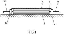
- FIG. 1 the arrangement of the individual layers is shown in the form in the lateral section, in the FIG. 2 from above.
- the mold 4 is coated with a very thin, few microns thick layer of a release agent 6, for example, a solvent-based suspension of low molecular weight PTFE, equipped, whose thickness in the FIG. 1 not shown in the right proportions.
- a release agent 6 for example, a solvent-based suspension of low molecular weight PTFE, equipped, whose thickness in the FIG. 1 not shown in the right proportions.
- the job is done with a rag. Thereafter, the suspension dries, resulting in a very thin film. Subsequently, the adhesive tape 1 is applied in a position on the inside of the mold 4.
- the individual adhesive tape strips 1, 2, 3 consist of a carrier film 10 to which an adhesive layer 11, in particular self-adhesive, is applied.
- the material layers 5 forming the body are distributed on the adhesive tape.
- a sealing film 21 is fixed over the material 5 with the aid of a second adhesive tape 24 so that a closed space results.
- the protective film 21 is shown only halfway.
- the protective film 21 is fixed on the mold 4 by the second adhesive tape 24.
- the air is removed.
- the resin is fed to the material layers 5 until they are soaked. There is the curing process.
- the sealing film 21 is removed and the finished molded article can be removed from the mold 4.
Landscapes
- Engineering & Computer Science (AREA)
- Mechanical Engineering (AREA)
- Chemical & Material Sciences (AREA)
- Composite Materials (AREA)
- Chemical Kinetics & Catalysis (AREA)
- Organic Chemistry (AREA)
- Laminated Bodies (AREA)
- Adhesive Tapes (AREA)
- Adhesives Or Adhesive Processes (AREA)
Description
- Die vorliegende Erfindung betrifft ein Verfahren gemäß Anspruch 1 zum Formen eines Körpers in einer Form, bei dem aus mehreren härtbaren Materialschichten ein Körper geformt wird, insbesondere ein Halbflügel eines Rotors, der in einer Windkraftanlage verbaut ist.
- Viele Bauteile, teilweise mit komplexen geometrischen Strukturen, werden hergestellt, indem aushärtbares Material wie zum Beispiel Epoxid- oder Polyesterharze in eine Form eingebracht wird, was anschließend ausgehärtet wird.
- Beispiele für solche Prozesse sind RTM (Resin Transfer Moulding) und VRTM (Vacuum-Assisted Resin Transfer Moulding). Das Resin Transfer Moulding ist ein Verfahren zur Herstellung von Formteilen aus Duroplasten und Elastomeren. Im Vergleich zum Pressen wird hierbei die Formmasse mittels Kolben von einer meist beheizten Vorkammer über Verteilerkanäle in das Formnest eingespritzt, worin sie unter Wärme und Druck aushärtet. Als Formmasse können Formaldehydharze (Phenolharze oder Aminoplaste) und Reaktionsharze (Polyester wie PET oder Epoxidharze) mit kleinen Füllstoffpartikeln und Elastomere verwendet werden.
- Zu Beginn eines Zyklus befindet sich eine vorplastifizierte und dosierte Formmasse in der Vorkammer. Zunächst wird das Werkzeug geschlossen. Danach wird die Formmasse ins Werkzeug eingespritzt und für eine bestimmte Zeit im Werkzeug belassen. Bei dieser sogenannten Verweilzeit kommt es zum Reagieren oder Vulkanisieren der Formmasse. Sie ist dabei von verschiedenen Faktoren abhängig (Harztyp, Füllstoff, Verarbeitungsdruck und -temperatur). Ist die Verweilzeit beendet, kann das Werkzeug geöffnet werden. Die zuvor eingefüllte Formmasse ist nun fest (ausgehärtet) und wird jetzt als Formteil bezeichnet. Dieses kann nun aus dem Werkzeug entformt werden. Danach erfolgt die Reinigung des Werkzeugs und ein neuer Zyklus kann beginnen.
- Die Menge der beim Einpressen und Nachpressen benötigen Formmasse sollte dabei immer größer als das Volumen des endgültigen Formteil sein, damit das Werkzeug vollständig befüllt wird. Somit wird garantiert, dass das Formteil vollständig ausgebildet ist und keine Luft eingepresst wird. Die dabei in der Vorkammer überschüssige, zurückgebliebene Formmasse, auch als Restkuchen bezeichnet, muss vor dem Beginn des neuen Zyklus entfernt werden und durch neue Formmasse ersetzt werden.
- Um Lufteinschlüsse zu vermeiden, wird meist zusätzlich die Kavität (Formhohlraum) evakuiert.
- Um auch lange Fasern oder Faserhalbzeuge (Prewovens/Preform) zu verarbeiten, werden diese zuvor in das Werkzeug eingelegt und mit der Formmasse umspritzt. Auch hier wird vorteilhafterweise meist zusätzlich die Kavität (Formhohlraum) evakuiert.
- Die "Prewovens-Verfahren" lassen sich nach Anzahl und Gestaltung der Harzangüsse einteilen. Im Folgenden wird der Eintrag des Harzes in das Faser-Halbzeug als Injektion bezeichnet, unabhängig davon auf welche Weise der Druckgradient erzeugt wird.
- Punktinjektion: Das Harz wird nur an einer Stelle in das Halbzeug injiziert. Beim Punktanguss kann die Fließfront Luft einschließen, was zu Fehlstellen führt.
- Mehrpunktinjektion: Durch mehrere Injektionsstellen kann die Form schneller mit Harz gefüllt werden. Der Einschluss von Luft kann durch geschickte Positionierung verhindert werden.
- Linien-Injektion: Bei der Linieninjektion wird nicht an einer punktförmigen Stelle injiziert sondern linienhaft am Rand der Form. Dies kann bei Bauteilen mit großer Streckung von Vorteil sein, da nur die kürzere Kantenlänge durchströmt werden muss.
- Fließkanal-Injektion: Das Harz wird durch einen breiten Kanal injiziert, der über oder unter dem Faser-Halbzeug liegt.
- Kaskaden-Injektion: Um den Druckgradienten gering zu halten, werden mehrere Injektionsstellen in Richtung der Fließfront angebracht. Es ist dazu jedoch notwendig, die Injektionsleitungen der Fließfront folgend zu öffnen und zu schließen.
- Als Formarten sind feste Formen, weiche Formen und Mischformen bekannt.
- Als Injektionsharze werden Harze verwendet, die eine niedrige Viskosität besitzen. Dadurch bleibt der Strömungswiderstand beim Durchströmen der Form gering und es sind kleinere Druckdifferenzen zum Füllen notwendig. Reaktionsharze für RTM-Verfahren werden als spezielle Injektionsharze angeboten, die aus einer Harz- und Härterkomponente bestehen. Niedrigreaktive Harzsysteme können bereits vor der Infusion gemischt werden. Sollen hochreaktive Harzsysteme verwendet werden, so können Harz und Härter erst unmittelbar in der Infusionsleitung beziehungsweise der Form gemischt werden. Auf diese Weise sind geringere Taktzeiten möglich. Verfahren, bei denen die Injektionsharz-Komponenten erst unmittelbar vor der Injektion gemischt werden, sind als RIM-Verfahren (Reaction Injection Moulding) bekannt.
- Weitere Details lassen sich dem Chemielexikon Römpp entnehmen, und zwar unter dem Stichwort "Spritzgießen" (2013 Georg Thieme Verlag, Dokumentkennung RD-19-03499, letzte Aktualisierung: Juli 2011).
- Zum Aufbau eines Körpers, beispielsweise dem (Halb-)Flügel eines Rotors, der in einer Windkraftanlage verbaut ist, werden Glasfasermatten verwendet, die als Teilschichten in eine geeignet gestaltete Form eingebracht werden. Anschließend werden die Schichten mit einem Harz verklebt und in der Form gehärtet, um ein faserverstärktes Polymer oder einen glasfaserverstärkten Kunststoff zu ergeben.
- Um ein einfaches und zerstörungsfreies Entformen zu gewährleisten, muss die Form, die den Negativ- und gegebenenfalls auch den Positivabdruck des zu bauenden Teils darstellt, mit einem anti-adhäsiven Material präpariert werden, das vor dem Aufbau der Schichten auf die Form aufgetragen wird.
- Dazu werden häufig Trennmittel eingesetzt wie Polyvinylalkohol oder Silikonwachse. Bekannt sind auch Trennmittel auf Silan- oder Siloxanbasis, beispielsweise die Produkte aus der Frekote-Serie der Firma Henkel. Des Weiteren wird PTFE-beschichtetes Glasgewebe eingesetzt, das in Form eines Klebebandes auf die Form aufgebracht wird und das Trennmittel ersetzt.
- Das Trennmittel ist in einer gleichmäßigen Schicht aufgebracht werden, und diese Schicht muss absolut glatt sein, damit die äußere Oberfläche des Körpers ebenfalls glatt ist.
- Die üblich eingesetzten flüssigen Trennmittel sind Lösungsmittel basiert und bedürfen einer Trocken- und Aushärtezeit von jeweils 20 bis 30 min. Die Applikation des Trennmittels dauert ebenfalls 20 bis 30 min.
Da je nach Anwender vor jedem Bauzyklus erneut mit Trennmittel ausgerüstet wird, entsteht dadurch insgesamt eine Totzeit von 1,5 h vor jedem Bauzyklus. - Als weiterer Nachteil ist zu nennen, dass die Trennmittel sich teilweise auf das Bauteil übertragen, was eine direkte anschließende Weiterverarbeitung zum Beispiel durch Lackieren erschwert. Das Trennmittel muss erst entfernt werden, was ebenfalls Zeit in Anspruch nimmt.
- Weiterhin ist bekannt, dass die Trennwirkung solcher Trennmittel nicht 100 %ig ist. Aufgrund der Tatsache, dass das Harz direkten Kontakt zur Form hat, lagert sich dadurch nach jedem weiteren Entformungszyklus an einigen Stellen eine geringe Menge Harz ab. Dieser Effekt summiert sich so stark, dass die Form je nach Schweregrad nach 200 Zyklen abgeschliffen und poliert werden muss, da sonst die Passgenauigkeit der entformten Bauteile nicht mehr gegeben ist.
- Einige der verwendeten Trennmittel basieren auf organischen Lösungsmitteln, welche beim Trocknen verdunsten und die Umgebungsluft belasten. In bestimmten Fällen müssen dafür extra Sicherheitsvorkehrungen getroffen werden, um die Brand- oder Explosionsgefahr zu minimieren.
- Eine wenig verbreitete Alternative besteht darin, die Bauteilform mit PTFE beschichteten Gewebeklebebändern auszukleiden. Diese müssen je nach Qualität weniger oft ausgetauscht werden und bieten eine gute Trennwirkung. Das spart vor allem Zeit, die für weitere Produktionszyklen genutzt werden kann.
- Nachteilig ist der Applikationsprozess des Gewebeklebebands in der dreidimensionalen Form, weil darauf geachtet werden muss, dass so wenig wie möglich Unregelmäßigkeiten wie Luftblasen unter dem Klebeband, überlappende Klebebandkanten oder Falten erzeugt werden.
Dies wird enorm erschwert durch die Steifigkeit und die fehlende Flexibilität des PTFE behandelten Glasgewebeträgers. - Bei der Herstellung eines PTFE beschichteten Gewebes wird üblicherweise ein sehr breiter Ballen auf der Ober- und der Unterseite mit PTFE benetzt und später in viele Rollen mit der gewünschten Breite aufgeschnitten. Dadurch ist an den Schnittkanten der Rollen kein PTFE. Dies wiederum hat zur Folge, dass sich das Gewebe und damit das Klebeband in der Form mit Flüssigharz vollsaugen und somit die Trennwirkung beziehungsweise die Zahl der Zyklen bis zum kompletten Austausch des Tapes reduziert wird.
- Es gibt große qualitative Unterschiede zwischen den PTFE-behandelten Glasgewebeträgern. Kaum zu verhindern sind sogenannte Mikrorisse in der PTFE-Schicht, in die Harz eindringen kann. Je nach Qualität treten diese Risse mehr oder weniger häufig auf. Diese fahren dazu, dass sich das Klebeband in der Mitte mit Harz vollsaugt, was wie im vorigen Absatz beschrieben, zu einer Reduktion der Lebenszeit führt.
- Weiterhin lässt sich nicht verhindern, dass das Glasfasergewebe (so wie jedes Gewebe) an den Schnittkanten ausfranzt und einzelne Fasern in die Form stehen. Wenn das Bauteil entformt wird, führt das dazu, dass die Faser und teilweise das Klebeband mit herausgerissen werden. Eine einmal herbeigeführte Verletzung dieser Art vergrößert sich entsprechend schnell, so dass die entstehende Lücke geflickt werden muss. Die neu entstandenen Kanten sind ebenfalls empfindlich, so dass dies ein sich selbstverschlechternden Prozess darstellt.
- Somit verliert auch ein mit PTFE beschichtetes Gewebeklebeband nach und nach seine Trennwirkung, so dass dieses nach zum Beispiel 30 Entformungen ausgetauscht werden muss.
- Aus der
US 2012/312469 A1 ist eine Form zur Herstellung eines Windradflügels bekannt, bei dem eine Form mit einer Lage eines nichtklebenden Liners ausgekleidet wird. Der Liner kann aus einer Folie bestehen, die Fluorpolymere enthält. Dadurch wird vermieden, dass der Liner am Verbundwerkstoff des Windradflügels anhaftet. Falls Fehlstellen oder Löcher in der Linerschicht auftreten, ist vorgesehen, Abschnitte des Liners selbstklebend auszurüsten, die dann auf die Fehlstellen aufgebracht werden können. - Die
US 2004/115299 A1 offenbart einen wiederverwendbaren Vakuumbeutel, der zum Aufbringen mindestens einer Dichtmittelraupe konfiguriert ist, wobei der Dichtmittelwulst während der Herstellung eines Verbundteils auf dem Formwerkzeug eine vakuumdichte Abdichtung des wiederverwendbaren Vakuumbeutels mit einem Formwerkzeug bereitstellt, wobei der wiederverwendbare Vakuumbeutel mindestens eine elastomere Schicht mit Polymeren umfasst. Die elastomere Schicht ist mit dem Formwerkzeug abdichtbar ist und weist einen umlaufenden Dichtungsflansch auf. - Des Weiteren ist ein Fluorelastomerstreifen mit Polymeren vorgesehen, der sich im Wesentlichen entlang des Dichtungsflansches erstreckt. Die Polymere der Elastomerschicht vernetzen bei einer erhöhten Temperatur mit den Polymeren des Fluorelastomerstreifens vernetzen, so dass eine dauerhafte Verbindung zwischen dem Dichtungsflansch gebildet wird.
- Die
US 2004/0127121 A1 beschreibt ein Klebeband mit einem Träger, der eine Releaseschicht und eine Trägerschicht aufweist. Des Weiteren sind ein Gitterstoff sowie eine druckempfindliche Klebeschicht vorhanden, die über dem Gitterstoff und der Substratschicht des Trägers aufgetragen ist. Als Polymer in der Releaseschicht kann Polytetrafluorethylen verwendet werden. - Aufgabe der vorliegenden Erfindung ist, ein Verfahren zum Formen eines Körpers aus aushärtbaren Materialschichten in einer Form anzugeben, das bezüglich seiner Zyklusschritte optimiert ist durch ein verbessertes Klebeband, das zwischen den Materialschichten und der Form eingesetzt wird.
- Gelöst wird diese Aufgabe durch ein Verfahren, wie es im Hauptanspruch niedergelegt, ist. Gegenstand der Unteransprüche sind vorteilhafte Weiterentwicklungen des Erfindungsgegenstandes.
- Demgemäß betrifft die Erfindung ein Verfahren zum Formen eines Körpers in einer Form gemäß Anspruch 1.
- Gemäß einer bevorzugten Variante des Verfahrens wird vor dem Aufbringen des Klebebands die Innenseite der Form mit einem Trennmittel ausgerüstet.
- Weiter vorzugsweise erfolgt das Aushärten der Materialschichten unter Vakuum.
- Die einzelnen Verfahrensschritte sind beispielsweise in der
EP 2 388 131 A1 umfassender erläutert. - Als Fluorpolymere oder fluorhaltige Polymere werden im Rahmen dieser Offenbarung sowie allgemein sowohl fluorhaltige Polymere mit ausschließlich Kohlenstoffatomen als auch solche mit Heteroatomen in der Hauptkette bezeichnet. Vertreter der ersten Gruppe sind Homo- und Copolymere olefinisch-ungesättigter fluorierter Monomeren.
- Die Einteilung der aus diesen Monomeren resultierenden Fluorpolymere erfolgt in die Kategorien Polytetrafluorethylen, Fluorthermoplaste, Fluorkautschuke und die daraus durch Vulkanisation gewonnenen Fluorelastomere. Wichtigste Vertreter der Fluorpolymere mit Heteroatomen in der Hauptkette sind die Polyfluorsiloxane und Polyfluoralkoxyphosphazene.
- Vorzugsweise enthält die Trägerfolie zu 50 Gew.-%, weiter vorzugsweise zu 75 Gew.-%, besonders vorzugsweise zu 90 Gew.-%, ganz besonders vorzugsweise zu 95 Gew.-% ein oder mindestens zwei Fluorpolymere (jeweils bezogen auf die Gesamtzusammensetzung der Trägerfolie).
- Weiter vorzugsweise bestehen die die Trägerfolie bildenden Polymere zu 100 Gew.-% aus einem oder mindestens zweien Fluorpolymeren. Den Fluorpolymeren können zusätzlich optional die später geschilderten Additive zugesetzt sein. Letztere sind - wie gesagt - nicht zwingend, sondern können auch nicht verwendet werden.
- Als Fluorpolymere sind insbesondere PTFE (Polytetrafluorethylen), ETFE (Poly(ethylen-co-tetrafluoroethylen)), FEP (Poly(tetrafluorethylen-co-hexafluorpropylen)), PVDF (Poly(1,1-difluorethen)) oder PFA (Perfluoralkoxy-Polymere) geeignet oder Gemische aus zwei oder mehreren der genannten Fluorpolymere.
- PTFE bezeichnet Fluorpolymere, die aus Tetrafluorethen-Monomeren zusammengesetzt sind.
- ETFE ist ein fluoriertes Copolymer bestehend aus den Monomeren Chlortrifluorethylen oder auch Tetrafluorethylen und Ethylen.
- FEP, auch fluoriertes Ethylen-Propylen-Copolymer genannt, bezeichnet Copolymere aus Tetrafluorethen und Hexafluorpropen.
- PVF ist ein aus Vinylfluorid hergestelltes Polymer (Polyvinylfluorid).
- PCTFE ist ein aus Chlortrifluorethylen aufgebautes Polymer (Polychlortrifluorethylen).
- ECTFE ist ein Copolymer bestehend aus Ethylen und Chlortrifluorethylen PVDF bezeichnet aus 1,1-Difluorethen (Vinylidenfluorid) herstellbare Fluorpolymere. PFA bezeichnet Copolymere mit Gruppierungen wie

- Die Fluorpolymere können mit weiteren Polymeren vermischt sein, wobei eine gute Mischbarkeit der Fluorpolymere mit den anderen Polymeren gegeben sein muss. Geeignete Polymere sind olefinische Polymere wie Homo- oder Copolymere von Olefinen wie Ethylen, Propylen oder Butylen (der Begriff Copolymer ist hier sinngemäß dahingehend zu verstehen, dass er Terpolymere mit einschließt), Polypropylenhomopolymere oder Polypropylencopolymere einschließlich der Block-(Impact-) und Randompolymere.
Weitere Polymere können allein oder in Mischung aus der Gruppe der Polyester wie insbesondere Polyethylenterephthalat (PET), Polyamide, Polyurethane, Polyoxymethylen, Polyvinylchlorid (PVC), Poylethylennaphtalat (PEN), Ethylenvinylalkohol (EVOH), Polyvinylidenchlorid (PVDC), Polyvinylidenfluorid (PVDF), Polyacrylnitril (PAN), Polycarbonat (PC), Polyamid (PA), Polyethersulfon (PES), Polyimid (PI), Polyarylensulfide und/oder Polyarylenoxide ausgewählt werden. - Die Polymere zur Bildung der Trägerfolie können in Reinform oder in Blends mit Additiven wie Antioxidantien, Lichtschutzmitteln, Antiblockmitteln, Gleit- und Verarbeitungshilfsmitteln, Füllstoffen, Farbstoffen, Pigmenten Treib- oder Nucleierungsmitteln vorliegen.
Vorzugsweise weist die Folie - mit Ausnahme von Farbstoffen - keines der genannten Additive auf. Farbstoffe werden bevorzugt eingesetzt, sind aber auch nicht zwingend vorhanden. - Die Trägerfolie besteht aus einem zumindest zweischichtigen Laminat aus zwei oder mehr Folienlagen. Bevorzugt besteht die mehrschichtige Trägerfolie aus bis zu zehn Folienlagen, insbesondere aus zwei bis fünf Folienlagen.
Die äußerste Folienlage, also die, die den den Körper bildende Materialschichten zugewandt ist, ist die ein oder mindestens zwei Fluorpolymere enthaltende Trägerfolie. Zwischen dieser Trägerfolie und der Klebemasse können weitere Folienlagen aus beliebigem Material vorhanden sein, (zum Beispiel aus Polyethylen, Polypropylen, Polyester, PA, PVC und andere Folien). Die weiteren Folienlagen können auch aus dem gleichen oder identischen Material bestehen wie die äußerste Folienlage. - Gemäß einer bevorzugten Ausführungsform der Erfindung besteht die Trägerfolie aus mindestens zwei Folienlagen, wobei die beiden äußeren Folienlagen unterschiedlich eingefärbt sind, vorzugsweise aus genau zwei.
Auf diese Weise entsteht ein einfacher, aber klar erkennbarer Verschleißnachweis. Wenn die äußerste Folienlage an einigen Stellen aufgrund des Verschleißes durchgescheuert ist, schimmert an diesen Stellen die darunter befindliche, wie erwähnt andersfarbige Folienlage durch (selbstverständlich sollten die Färbungen so gewählt werden, dass ein entsprechender Kontrast entsteht). Wenn also die untere Folienlage zu sehen ist, ist dies ein Anzeichen, dass es Zeit wird, das Klebeband auszutauschen. - Gemäß einer bevorzugten Ausführungsform liegt die Dicke der Trägerfolie zwischen 15 und 350 µm, vorzugsweise zwischen 30 und 200 µm, weiter vorzugsweise zwischen 50 und 150 µm.
- Vorzugsweise ist die auf der Trägerfolie aufgebrachte Klebemasse eine Haftklebemasse, also eine Klebemasse, die bereits unter relativ schwachem Andruck eine dauerhafte Verbindung mit fast allen Haftgründen erlaubt und nach Gebrauch im Wesentlichen rückstandsfrei vom Haftgrund wieder abgelöst werden kann. Eine Haftklebemasse wirkt bei Raumtemperatur permanent haftklebrig, weist also eine hinreichend geringe Viskosität und eine hohe Anfassklebrigkeit auf, so dass sie die Oberfläche des jeweiligen Klebegrunds bereits bei geringem Andruck benetzt. Die Verklebbarkeit der Klebemasse beruht auf ihren adhäsiven Eigenschaften und die Wiederablösbarkeit auf ihren kohäsiven Eigenschaften.
- Um aus dem Träger ein Klebeband herzustellen, kann auf alle bekannten Klebemassensysteme zurückgegriffen werden. Neben Natur- oder Synthesekautschuk basierten Klebemassen sind insbesondere Silikonklebemassen sowie Polyacrylatklebemassen, vorzugsweise eine niedermolekulare Acrylatschmelzhaftklebemasse, verwendbar.
- Bevorzugt werden Klebemassen, die auf Acrylat oder Silikon basieren.
- Die Klebemasse kann aus der Gruppe der Naturkautschuke oder der Synthesekautschuke oder aus einem beliebigen Blend aus Naturkautschuken und/oder Synthesekautschuken gewählt werden, wobei der Naturkautschuk oder die Naturkautschuke grundsätzlich aus allen erhältlichen Qualitäten wie zum Beispiel Crepe-, RSS-, ADS-, TSR- oder CV-Typen, je nach benötigtem Reinheits- und Viskositätsniveau, und der Synthesekautschuk oder die Synthesekautschuke aus der Gruppe der statistisch copolymerisierten Styrol-Butadien-Kautschuke (SBR), der Butadien-Kautschuke (BR), der synthetischen Polyisoprene (IR), der Butyl-Kautschuke (IIR), der halogenierten Butyl-Kautschuke (XIIR), der Acrylatkautschuke (ACM), der Etylen-Vinylacetat-Copolymeren (EVA) und der Polyurethane und/oder deren Blends gewählt werden können.
- Weiterhin vorzugsweise können den Kautschuken zur Verbesserung der Verarbeitbarkeit thermoplastische Elastomere mit einem Gewichtsanteil von 10 bis 50 Gew.-% zugesetzt werden, und zwar bezogen auf den Gesamtelastomeranteil.
Stellvertretend genannt seien an dieser Stelle vor allem die besonders verträglichen Styrol-Isopren-Styrol (SIS)- und Styrol-Butadien-Styrol (SBS)-Typen. Geeignete Elastomere zum Abmischen sind auch zum Beispiel EPDM- oder EPM-Kautschuk, Polyisobutylen, Butylkautschuk, Ethylen-Vinylacetat, hydrierte Blockcopolymere aus Dienen (zum Beispiel durch Hydrierung von SBR, cSBR, BAN, NBR, SBS, SIS oder IR, solche Polymere sind zum Beispiel als SEPS und SEBS bekannt) oder Acrylatcopolymere wie ACM.
Daneben hat sich ein 100%-System auf Styrol-Isopren-Styrol (SIS) als geeignet erwiesen. - Eine Vernetzung ist vorteilhaft für die Verbesserung der Wiederabziehbarkeit des Klebebandes nach der Anwendung und kann thermisch oder durch Bestrahlung mit UV-Licht oder Elektronenstrahlen erfolgen.
Zum Zwecke der thermisch induzierten chemischen Vernetzung sind alle vorbekannten thermisch aktivierbaren chemischen Vernetzer wie beschleunigte Schwefel- oder Schwefelspendersysteme, Isocyanatsysteme, reaktive Melamin-, Formaldehyd- und (optional halogenierter) Phenol-Formaldehydharze beziehungsweise reaktive Phenolharz- oder Diisocyanatvernetzungssysteme mit den entsprechenden Aktivatoren, epoxidierte Polyester- und Acrylat-Harze sowie deren Kombinationen einsetzbar.
Die Vernetzer werden vorzugsweise aktiviert bei Temperaturen über 50 °C, insbesondere bei Temperaturen von 100 °C bis 160 °C, ganz besonders bevorzugt bei Temperaturen von 110 °C bis 140 °C. - Die thermische Anregung der Vernetzer kann auch durch IR-Strahlen oder hochenergetische Wechselfelder erfolgen.
- Verwendbar sind Klebemassen auf Lösemittelbasis, auf wässriger Basis oder auch als Hotmeltsystem. Auch eine Masse auf Acrylathotmelt-Basis ist geeignet, wobei diese einen K-Wert von mindestens 20 aufweisen kann, insbesondere größer 30, erhältlich durch Aufkonzentrieren einer Lösung einer solchen Masse zu einem als Hotmelt verarbeitbaren System
- Das Aufkonzentrieren kann in entsprechend ausgerüsteten Kesseln oder Extrudern stattfinden, insbesondere beim damit einhergehenden Entgasen ist ein Entgasungsextruder bevorzugt.
- Eine derartige Klebemasse ist in der
DE 43 13 008 A1 dargelegt. Die Klebemasse auf Acrylathotmelt-Basis kann aber auch chemisch vernetzt sein. - In einer weiteren Ausführungsform werden als Selbstklebemassen Copolymerisate aus (Meth)acrylsäure und deren Estern mit 1 bis 25 C-Atomen, Malein-, Fumar- und/oder Itaconsäure und/oder deren Estern, substituierten (Meth)acrylamiden, Maleinsäureanhydrid und anderen Vinylverbindungen, wie Vinylestern, insbesondere Vinylacetat, Vinylalkoholen und/oder Vinylethern eingesetzt.
- Der Restlösungsmittel-Gehalt sollte unter 1 Gew.-% betragen.
- Eine Klebemasse, die sich ebenfalls als geeignet zeigt, ist eine niedermolekulare Acrylatschmelzhaftklebemasse, wie sie unter der Bezeichnung acResin UV oder Acronal®, insbesondere Acronal® DS 3458 oder AC Resin A 260UV, von der BASF geführt wird. Diese Klebemasse mit niedrigem K-Wert erhält ihre anwendungsgerechten Eigenschaften durch eine abschließende strahlenchemisch ausgelöste Vernetzung.
- Abschließend sei erwähnt, dass auch auf Polyurethan basierende Kleber geeignet sind.
- Zur Optimierung der Eigenschaften kann die zum Einsatz kommende Selbstklebemasse mit einem oder mehreren Additiven wie Klebrigmachern (Harzen), Weichmachern, Füllstoffen, Pigmenten, UV-Absorbern, Lichtschutz-, Alterungsschutz-, Vernetzungsmitteln, Vernetzungspromotoren oder Elastomeren abgemischt sein.
- Klebrigmacher sind beispielsweise Kohlenwasserstoffharze (zum Beispiel aus ungesättigten C5- oder C7-Monomeren), Terpenphenolharze, Terpenharze aus Rohstoffen wie α- oder ß-Pinen, aromatische Harze wie Cumaron-Inden-Harze oder Harze aus Styrol oder α-Methylstyrol wie Kolophonium und seine Folgeprodukte wie disproportionierte, dimerisierte oder veresterte Harze, wobei Glycole, Glycerin oder Pentaerythrit eingesetzt werden können. Besonders geeignet sind alterungsstabile Harze ohne olefinische Doppelbindung wie zum Beispiel hydrierte Harze.
Auf die Darstellung des Wissensstandes im "Handbook of Pressure Sensitive Adhesive Technology" von Donatas Satas (van Nostrand, 1989) sei ausdrücklich hingewiesen. - Geeignete Füllstoffe und Pigmente sind beispielsweise Ruß, Titandioxid, Calciumcarbonat, Zinkcarbonat, Zinkoxid, Silicate oder Kieselsäure.
- Geeignete Weichmacher sind beispielsweise aliphatische, cycloaliphatische und aromatische Mineralöle, Di- oder Poly-Ester der Phthalsäure, Trimellitsäure oder Adipinsäure, flüssige Kautschuke (zum Beispiel Nitril- oder Polyisoprenkautschuke), flüssige Polymerisate aus Buten und/oder Isobuten, Acrylsäureester, Polyvinylether, Flüssig- und Weichharze auf Basis der Rohstoffe zu Klebharze, Wollwachs und andere Wachse oder flüssige Silikone.
- Vernetzungsmittel sind beispielsweise Phenolharze oder halogenierte Phenolharze, Melamin- und Formaldehydharze. Geeignete Vernetzungspromotoren sind zum Beispiel Maleinimide, Allylester wie Triallylcyanurat, mehrfunktionelle Ester der Acryl- und Methacrylsäure.
- Die Verankerung ist üblicherweise so stark, dass ein solches Klebeband problemlos von einer Rolle abgewickelt werden kann, ohne dass die Verankerung der Klebemasse reißt und es zum so genannten Umspulen der Klebemasse kommt (die Klebemasse befindet sich dann auf der Rückseite des Trägers). Des Weiteren wird von den meisten Haftklebebändern erwartet, dass diese vom Untergrund wieder abgelöst werden können, also möglichst spurlos wieder aufgenommen werden können. Das heißt, das Klebeband darf nicht zwischen Träger und Klebemasse adhäsiv brechen.
- Gemäß einer bevorzugten Ausführungsform liegt der Masseauftrag der Klebemasse auf die Trägerfolie zwischen 10 und 200 g/m2; vorzugsweise zwischen 20 und 100 g/m2, besonders vorzugsweise zwischen 30 und 75 g/m2.
- Als Materialschichten zur Bildung des Formteils wird insbesondere Fasermaterial (wie zum Beispiel GFK (glasfaserverstärkter Kunststoff), CFK (kohlenstofffaserverstärkter Kunststoff) oder Prepreg und so weiter) verwendet.
- Prepeg bezeichnet ein Halbzeug, bestehend aus Endlosfasern und einer ungehärteten duroplastischen Kunststoffmatrix, das vor allem. im Leichtbau Verwendung findet. Die Endlosfasern können als reine unidirektionale Schicht, als Gewebe oder Gelege vorliegen.
- Zur Erhöhung der Adhäsion zwischen der Klebemasse und dem Trägermaterial oder zwischen Trennlack und Trägermaterial kann das Trägermaterial zur Erhöhung der Oberflächenenergie einer Coronabehandlung unterzogen werden.
- Vorteilhaft ist die Verwendung einer Primerschicht zwischen Trägerfolie und Klebmasse zur Verbesserung der Haftung der Klebmasse auf der Folie und somit der rückstandsfreien Wiederabziehbarkeit nach der Anwendung.
- Des Weiteren ist ein Ätzen der Folie vorteilhaft, um die Klebemasse verankern zu können.
- Beschreibungen der üblicherweise für Klebebänder verwendeten Klebmassen sowie Primern finden sich zum Beispiel im "Handbook of Pressure Sensitive Adhesive Technology" von Donatas Satas (van Nostrand, 1989).
- Der allgemeine Ausdruck "Klebeband" umfasst im Sinne dieser Offenbarung alle flächigen Gebilde wie in zwei Dimensionen ausgedehnte Folien oder Folienabschnitte, Bänder mit ausgedehnter Länge und begrenzter Breite, Bandabschnitte und dergleichen, letztlich auch Stanzlinge oder Etiketten.
- Das Klebeband kann sowohl in Form einer Rolle, also in Form einer archimedischen Spirale auf sich selbst aufgerollt, als auch klebmasseseitig eingedeckt mit Trennmaterialien wie silikonisiertem Papier oder silikonisierter Folie hergestellt werden. Als Trennmaterial eignet sich bevorzugt ein nicht-fusselndes Material wie eine Kunststofffolie oder ein gut verleimtes, langfaseriges Papier.
- Die Klebebänder weisen insbesondere Lauflängen von 1000 bis 30.000 m auf. Als Breite der Rollen werden üblicherweise 10, 15, 19, 25 und 30 mm gewählt.
- Ein folienartiger Träger, der vollständig oder zu mindestens 50 Gew.-% aus fluoriertem Polymer besteht zeigt nicht die oben beschriebenen Nachteile des Ausfransens durch Glasfasern oder Gewebe. Auch die Steifigkeit eines solchen Klebebands ist viel niedriger, und es passt sich deshalb gut an die Form an. Das Trägermaterial zeigt eine gewisse Dehnbarkeit, die zusätzlich bei der Anpassung an die Form hilft.
- Weiterhin ist die innere Festigkeit eines solchen Trägermaterials deutlich höher, so dass auch bei größeren auftretenden Kräften kein Abspalten von Tragerteilen zu beobachten ist.
- Im Folgenden wird die Erfindung anhand eines Beispiels näher erläutert, ohne auch hiermit dieselbe in irgendeiner Art und Weise einschränken zu wollen.
-
- 50 g/m2 Silikonklebemasse (Dow Corning® Q2-7406)
- 100 µm PTFE-Träger (NORTON® 124 Sintered Extruded PTFE Film)
- Aktivierung des Trägers (durch übliches Ätzverfahren)
-
- 50 g/m2 Silikonklebemasse (Dow Corning® Q2-7406)
- 150 µm PTFE-beschichtetes Glasgewebe (Träger)
- Aktivierung des Trägers (durch übliches Ätzverfahren)
- Das Klebeband gemäß Beispiel 1 lässt sich auch nach mehreren Entformungsschritten nahezu rückstandsfrei vom Untergrund ablösen und zeigte über die gesamte Zeit eine gute Trennwirkung.
- Im Fall des Gegenbeispiels beobachtet man beim Ablösen des Klebebands bereits nach dem ersten Zyklus Rückstände von Klebmasse auf der Form. Nach drei bis fünf Zyklen ist ein Spalten des Trägers in z-Richtung zu beobachten, das heißt, der Träger spaltet in sich, und es bleibt teilweise eine Schicht PTFE auf der Oberfläche zurück, die sich nur schwer entfernen lässt.
- Die Klebebänder werden dazu in eine mit einem üblichen Trennmittel, zum Beispiel Frekote NC 44 (ein Trennmittel enthaltend eine Mischung aus Dibutylether und Polydimethylsiloxan (PDMS), was ein Gemisch aus vollständig methylierten linearen Siloxan-Polymeren mit endständigen Trimethylsiloxat-Einheiten ist) oder ME 143 der Firma Miller Stephenson (ein lösungsmittelbasierte Suspension von niedermolekularem PTFE) ausgerüstete Form eingeklebt. Entsprechend der
Figur 1 werden mehrere Bauzyklen durchgeführt. Die Temperatur während des Aushärtens beträgt 80 bis 90 °C. Das Vakuum beträgt 0,1 bar. - Es werden bis zu zehn Bauzyklen simuliert.
- Im Folgenden soll das erfindungsgemäße, in dem Anspruch 1 definierte, Verfahren anhand mehrerer Figuren beispielhaft näher erläutert werden, ohne die Erfindung auf diese Ausführungsformen zu beschränken.
- Es zeigen:
- Figur 1
- die Anordnung der einzelnen Schichten in der Form im seitlichen Schnitt,
- Figur 2
- die Anordnung der einzelnen Schichten in der Form von oben und
- Figur 3
- einen vereinfachten Detailausschnitt der
Figur 1 . - In der
Figur 1 ist die Anordnung der einzelnen Schichten in der Form im seitlichen Schnitt dargestellt, in derFigur 2 von oben. - Die Form 4 wird mit einer sehr dünnen, wenige µm dicke Schicht eines Trennmittels 6, zum Beispiel einer lösungsmittelbasierten Suspension von niedermolekularem PTFE, ausgerüstet, deren Dicke in der
Figur 1 nicht im richtigen Verhältnis gezeigt ist. Der Auftrag erfolgt mit einem Lappen. Danach trocknet die Suspension, woraus ein sehr dünner Film resultiert. Anschließend wird das Klebeband 1 in einer Lage auf der Innenseite der Form 4 aufgebracht. - In der
Figur 3 ist gezeigt, dass die Kanten der einzelnen Streifen des Klebebands 1, 2 ,3 stoß an stoß liegen, also keine Zwischenräume aufweisen. Die einzelnen Klebebandstreifen 1, 2, 3 bestehen aus einer Trägerfolie 10, auf die eine Klebemassenschicht 11, insbesondere Selbstklebemasse, aufgebracht ist. - Nach dem Verkleben des Klebebands 1 werden die den Körper bildende Materialschichten 5 auf dem Klebeband verteilt.
- Anschließend wird eine Dichtfolie 21 so über dem Material 5 mit Hilfe eines zweiten Klebebands 24 fixiert, dass sich ein abgeschlossener Raum ergibt.
- In der
Figur 2 ist die Schutzfolie 21 nur zur Hälfte gezeigt. Die Schutzfolie 21 wird von dem zweiten Klebeband 24 auf der Form 4 fixiert. - Durch einen Abgang 22 wird die Luft entfernt. Über einen Zugang 23 wird das Harz den Materialschichten 5 zugeführt, bis diese getränkt sind.
Es erfolgt der Aushärtungsprozeß. - Wenn dieser abgeschlossen ist, wird die Dichtfolie 21 entfernt und der fertige Formkörper kann der Form 4 entnommen werden.
Claims (11)
- Verfahren zum Formen eines Körpers in einer Form (4), umfassend die folgenden Schritte:• Aufbringen eines Klebebands (1) auf der Innenseite einer Form (4), wobei die Kanten der einzelnen Streifen des Klebebands (1, 2 ,3) Stoß an Stoß liegen, also keine Zwischenräume aufweisen• Verteilen der den Körper bildende Materialschichten (5) auf dem Klebeband (1)• Aushärtung der Materialschichten (5)• Entfernen des Körpers aus der Form (4) wobei die einzelnen Klebebandstreifen (1, 2, 3) aus einer Trägerfolie (10) bestehen, auf die einseitig eine Klebemassenschicht (11), insbesondere Selbstklebemasse ausgebracht ist, und die Trägerfolie (10) ein oder mindestens zwei Fluorpolymere enthält, wobei die Trägerfolie (10) aus einem zumindest zweischichtigen Laminat aus zwei oder mehr Folienlagen besteht, wobei die äußerste Folienlage, also die Folienlage, die den den Körper bildenden Materialschichten zugewandt ist, die die ein oder mindestens zwei Fluorpolymere enthaltende Folienlage ist.
- Verfahren nach Anspruch 1,
dadurch gekennzeichnet, dass
die Trägerfolie (10) zu 50 Gew.-%, weiter vorzugsweise zu 75 Gew.-%, besonders vorzugsweise zu 90 Gew.-%, ganz besonders vorzugsweise zu 95 Gew.-% ein oder mindestens zwei Fluorpolymere, jeweils bezogen auf die Gesamtzusammensetzung der Trägerfolie, enthält oder die die Trägerfolie (10) bildenden Polymere zu 100 Gew.-% aus einem oder mindestens zweien Fluorpolymeren bestehen. - Verfahren nach den Ansprüchen 1 oder 2,
dadurch gekennzeichnet, dass
als Fluorpolymere PTFE (Polytetrafluorethylen), ETFE (Poly(ethylen-co-tetrafluoroethylen)), FEP (Poly(tetrafluorethylen-co-hexafluorpropylen)), PVF (Polyvinylfluorid), PCTFE (Polychlortrifluorethylen), ECTFE (Poly(ethylen-co-chlortrifluorethylen), PVDF (Poly(1,1-difluorethen)) oder PFA (Perfluoralkoxy-Polymere) oder Gemische aus zwei oder mehreren der genannten Fluorpolymere eingesetzt werden. - Verfahren nach zumindest einem der Ansprüche 1 bis 3,
dadurch gekennzeichnet, dass
die Fluorpolymere mit weiteren Polymeren vermischt sind wie olefinische Polymere wie Homo- oder Copolymere von Olefinen wie Ethylen, Propylen oder Butylen, Polyester wie insbesondere Polyethylenterephthalat (PET), Polyamide, Polyurethane, Polyoxymethylen, Polyvinylchlorid (PVC), Poylethylennaphtalat (PEN), Ethylenvinylalkohol (EVOH), Polyvinylidenchlorid (PVDC), Polyvinylidenfluorid (PVDF), Polyacrylnitril (PAN), Polycarbonat (PC), Polyamid (PA), Polyethersulfon (PES), Polyimid (PI), Polyarylensulfide und/oder Polyarylenoxide. - Verfahren nach zumindest einem der vorherigen Ansprüche,
dadurch gekennzeichnet, dass
die Dicke der Trägerfolie (10) zwischen 15 und 350 µm, vorzugsweise zwischen 30 und 200 µm, weiter vorzugsweise zwischen 50 und 150 µm liegt. - Verfahren nach zumindest einem der vorherigen Ansprüche,
dadurch gekennzeichnet, dass
die auf der Trägerfolie (10) aufgebrachte Klebemasse (11) eine Haftklebemasse, insbesondere auf Acrylat- oder Silikonbasis ist. - Verfahren nach zumindest einem der vorherigen Ansprüche,
dadurch gekennzeichnet, dass
die Trägerfolie (10) aus bis zu zehn Folienlagen, besonders vorzugsweise aus zwei bis fünf Folienlagen besteht. - Verfahren nach zumindest einem der vorherigen Ansprüche,
dadurch gekennzeichnet, dass
die Trägerfolie (10) aus mindestens zwei Folienlagen besteht, wobei die beiden äußeren Folienlagen unterschiedlich eingefärbt sind, vorzugsweise aus genau zwei. - Verfahren nach zumindest einem der vorherigen Ansprüche,
dadurch gekennzeichnet, dass
der Masseauftrag der Klebemasse (11) auf die Trägerfolie (10) zwischen 10 und 200 g/m2; vorzugsweise zwischen 20 und 100 g/m2, besonders vorzugsweise zwischen 30 und 75 g/m2 beträgt. - Verfahren nach zumindest einem der vorherigen Ansprüche,
dadurch gekennzeichnet, dass
vor dem Aufbringen des Klebebands (1) die Innenseite der Form (4) mit einem Trennmittel ausgerüstet wird. - Verfahren nach zumindest einem der vorherigen Ansprüche,
dadurch gekennzeichnet, dass
das Aushärten der Materialschichten (5) unter Vakuum stattfindet.
Applications Claiming Priority (3)
| Application Number | Priority Date | Filing Date | Title |
|---|---|---|---|
| DE102013215146 | 2013-08-01 | ||
| DE102013221847.8A DE102013221847A1 (de) | 2013-08-01 | 2013-10-28 | Verfahren zum Formen eines Körpers in einer Form |
| PCT/EP2014/065585 WO2015014646A1 (de) | 2013-08-01 | 2014-07-21 | Verfahren zum formen eines körpers in einer form |
Publications (2)
| Publication Number | Publication Date |
|---|---|
| EP3027392A1 EP3027392A1 (de) | 2016-06-08 |
| EP3027392B1 true EP3027392B1 (de) | 2019-03-13 |
Family
ID=52342021
Family Applications (1)
| Application Number | Title | Priority Date | Filing Date |
|---|---|---|---|
| EP14741321.5A Active EP3027392B1 (de) | 2013-08-01 | 2014-07-21 | Verfahren zum formen eines körpers in einer form |
Country Status (6)
| Country | Link |
|---|---|
| US (1) | US20160158971A1 (de) |
| EP (1) | EP3027392B1 (de) |
| CN (1) | CN105579222B (de) |
| DE (1) | DE102013221847A1 (de) |
| DK (1) | DK3027392T3 (de) |
| WO (1) | WO2015014646A1 (de) |
Families Citing this family (13)
| Publication number | Priority date | Publication date | Assignee | Title |
|---|---|---|---|---|
| DE102014215079A1 (de) * | 2014-07-31 | 2016-02-04 | Tesa Se | Verfahren zum Formen eines Körpers in einer Form |
| DE102015213507A1 (de) * | 2015-07-17 | 2017-01-19 | Tesa Se | Klebeband, das insbesondere in einem Verfahren zum Formen eines Körpers in einer Form eingesetzt werden kann |
| DE102015217310A1 (de) | 2015-09-10 | 2017-03-16 | Tesa Se | Verfahren zum Verbinden zweier faserverstärkter Kunststoffbauteile |
| DE102015217312A1 (de) | 2015-09-10 | 2017-03-16 | Tesa Se | Klebeband, das insbesondere in einem Verfahren zum Verbinden zweier faserverstärkter Kunststoffbauteile eingesetzt werden kann |
| CA2942015C (en) * | 2015-09-14 | 2019-01-15 | Bell Helicopter Textron Inc. | Method of forming pressure pad or other flexible element for use during cure of composite materials |
| DE102016202424A1 (de) * | 2016-02-17 | 2017-08-17 | Tesa Se | Verfahren zur Herstellung eines Klebebandes mittels Plasmalamination |
| DE102016202396A1 (de) * | 2016-02-17 | 2017-08-17 | Tesa Se | Verankerung von Silikonklebmassen auf Fluorpolymerfolien durch Coronabehandlung |
| CN109153197B (zh) * | 2016-05-27 | 2020-11-03 | Rimtec株式会社 | 复合材料成型体的制造方法 |
| CN107471503B (zh) * | 2016-06-08 | 2019-08-30 | 中材科技风电叶片股份有限公司 | 风电叶片模具表面的防护层施工方法 |
| CN110093114B (zh) * | 2018-01-30 | 2021-09-10 | 日东电工(上海松江)有限公司 | 一种复合材料成型用的防粘胶带及其制造方法和用途 |
| CN108410385A (zh) * | 2018-03-16 | 2018-08-17 | 佛山市利丰日用品有限公司 | 一种环保型装饰贴面材料及其制备方法 |
| CN113085221B (zh) * | 2021-03-29 | 2022-04-26 | 北京化工大学 | 一种连续纤维增强热塑性树脂真空袋压成型装置及方法 |
| CN116021798B (zh) * | 2023-01-28 | 2023-10-20 | 哈尔滨远驰航空装备有限公司 | 一种进气道用复合材料零吸胶成型方法 |
Citations (4)
| Publication number | Priority date | Publication date | Assignee | Title |
|---|---|---|---|---|
| DE69805535T2 (de) * | 1997-10-14 | 2003-01-09 | Minnesota Mining And Mfg. Co., St. Paul | Schutzschichten und beschichtungen |
| US20040115299A1 (en) * | 2002-12-11 | 2004-06-17 | John Potter | Seal-less reusable vacuum bag |
| US20040127121A1 (en) * | 2002-12-31 | 2004-07-01 | Schwab Jeffrey J. | Adhesive tape |
| US20100096772A1 (en) * | 2006-04-25 | 2010-04-22 | Asahi Glass Company, Limited | Release film for semiconductor resin molds |
Family Cites Families (24)
| Publication number | Priority date | Publication date | Assignee | Title |
|---|---|---|---|---|
| US2819180A (en) * | 1951-11-10 | 1958-01-07 | Koenig Claus | Self-adhesive tape |
| US2989419A (en) * | 1957-05-14 | 1961-06-20 | Johnson & Johnson | Improving the adhesive bond and delamination resistance of fluorocarbon backed adhesive tape |
| DE2320197C3 (de) * | 1973-04-19 | 1979-05-17 | Beiersdorf Ag, 2000 Hamburg | Verfahren zur Herstellung von bahnen- oder blattförmigen Materialien mit einem Träger mit Polyurethan-Selbstklebeschicht |
| DE3727926A1 (de) * | 1986-08-27 | 1988-03-10 | Dornier Gmbh | Verfahren zur herstellung von formteilen |
| DE3911386A1 (de) * | 1989-04-07 | 1990-10-25 | Weigel Angela | Verfahren zur herstellung von formteilen aus kunststoff |
| DE4313008C1 (de) | 1993-04-21 | 1994-11-10 | Beiersdorf Ag | Selbstklebemasse auf Acrylathotmelt-Basis, Verfahren zu deren Herstellung und deren Verwendung |
| WO1996028519A1 (en) * | 1995-03-15 | 1996-09-19 | Nitto Denko Corporation | Pressure-sensitive adhesive composition and pressure-sensitive adhesive sheets made therefrom, and sealants, reinforcing sheets and pressure-sensitive adhesive sheets for printing produced therefrom |
| WO2000018555A1 (en) * | 1998-10-01 | 2000-04-06 | Airtech International, Inc. | Method of molding or curing a resin material at high temperatures using a multilayer release film |
| JP4034478B2 (ja) * | 1999-07-02 | 2008-01-16 | スリーエム イノベイティブ プロパティズ カンパニー | 感圧接着シート及びその製造方法 |
| US7147818B1 (en) * | 2002-05-16 | 2006-12-12 | The United States Of America As Represented By The Secretary Of The Army | Process and apparatus for improved composite fiber volume fraction and dimensional stability by removal of accumulated excess resin using the vacuum assisted resin transfer molding (VARTM) process |
| DE10322830A1 (de) * | 2003-05-19 | 2004-12-09 | Tesa Ag | Verfahren zur kontinuierlichen Herstellung von Polymeren aus vinylischen Verbindungen durch Substanz-beziehungsweise Lösungsmittelpolymerisation |
| JP2006247893A (ja) * | 2005-03-08 | 2006-09-21 | Nissha Printing Co Ltd | 転写フィルム、加飾フィルムおよび加飾品の製造方法並びに加飾品 |
| JP5322373B2 (ja) * | 2006-04-17 | 2013-10-23 | 日東電工株式会社 | 粘着テープ又はシート用基材、反射性及び/又は遮光性を有する粘着テープ又はシート、および液晶表示装置 |
| DE102006043065B3 (de) * | 2006-09-14 | 2007-10-31 | Federal-Mogul Deva Gmbh | Kunststoffgleitschicht und Gleitelement mit einer solchen |
| DE102008004388A1 (de) * | 2008-01-14 | 2009-07-16 | Tesa Ag | Geschäumte, insbesondere druckempfindliche Klebemasse, Verfahren zur Herstellung sowie die Verwendung derselben |
| US20090273111A1 (en) * | 2008-04-30 | 2009-11-05 | Bha Group, Inc. | Method of making a wind turbine rotor blade |
| DE102008024551A1 (de) * | 2008-05-21 | 2009-11-26 | Tesa Se | Verfahren zur Verkapselung von optoelektronischen Bauteilen |
| US20120312469A1 (en) * | 2010-03-03 | 2012-12-13 | Siemens Aktiengesellschaft | Method and mould for moulding a wind turbine blade |
| JP5516015B2 (ja) * | 2010-04-22 | 2014-06-11 | 凸版印刷株式会社 | 表面保護フィルム |
| DK2388131T3 (en) | 2010-05-20 | 2016-12-19 | Siemens Ag | A method for forming a wind turbine blade using a release film and the film |
| DE102011112964A1 (de) * | 2011-09-15 | 2013-03-21 | Evonik Industries Ag | PV-PSA-Laminat durch PSA-Lamination auf einen Release-Film |
| CA2758622A1 (en) * | 2011-11-17 | 2013-05-17 | Allan R. MANNINEN | Coextruded laser weld enabled polymer film or filament and fabrics made therefrom |
| US20150035204A1 (en) * | 2013-08-01 | 2015-02-05 | Intertape Polymer Corp. | Silicone adhesive tapes and method of masking using same |
| DE102014215079A1 (de) * | 2014-07-31 | 2016-02-04 | Tesa Se | Verfahren zum Formen eines Körpers in einer Form |
-
2013
- 2013-10-28 DE DE102013221847.8A patent/DE102013221847A1/de not_active Withdrawn
-
2014
- 2014-07-21 DK DK14741321.5T patent/DK3027392T3/en active
- 2014-07-21 EP EP14741321.5A patent/EP3027392B1/de active Active
- 2014-07-21 CN CN201480043499.2A patent/CN105579222B/zh not_active Expired - Fee Related
- 2014-07-21 WO PCT/EP2014/065585 patent/WO2015014646A1/de not_active Ceased
- 2014-07-21 US US14/908,302 patent/US20160158971A1/en not_active Abandoned
Patent Citations (4)
| Publication number | Priority date | Publication date | Assignee | Title |
|---|---|---|---|---|
| DE69805535T2 (de) * | 1997-10-14 | 2003-01-09 | Minnesota Mining And Mfg. Co., St. Paul | Schutzschichten und beschichtungen |
| US20040115299A1 (en) * | 2002-12-11 | 2004-06-17 | John Potter | Seal-less reusable vacuum bag |
| US20040127121A1 (en) * | 2002-12-31 | 2004-07-01 | Schwab Jeffrey J. | Adhesive tape |
| US20100096772A1 (en) * | 2006-04-25 | 2010-04-22 | Asahi Glass Company, Limited | Release film for semiconductor resin molds |
Also Published As
| Publication number | Publication date |
|---|---|
| CN105579222A (zh) | 2016-05-11 |
| US20160158971A1 (en) | 2016-06-09 |
| CN105579222B (zh) | 2019-08-09 |
| DE102013221847A1 (de) | 2015-02-05 |
| WO2015014646A1 (de) | 2015-02-05 |
| DK3027392T3 (en) | 2019-04-29 |
| EP3027392A1 (de) | 2016-06-08 |
Similar Documents
| Publication | Publication Date | Title |
|---|---|---|
| EP3027392A1 (de) | Verfahren zum formen eines körpers in einer form | |
| EP3174681B1 (de) | Verfahren zum formen eines körpers in einer form | |
| DE102007010171A1 (de) | Hitze-aktiviert verklebendes Flächenelement | |
| WO2015024726A1 (de) | STANZLING INSBESONDERE ZUM DAUERHAFTEN VERSCHLIEßEN VON LÖCHERN | |
| EP3325567B1 (de) | Verwendung eines klebebands in einem verfahren zum formen eines körpers in einer form | |
| DE202012004946U1 (de) | Lichtabsorbierende hitzeaktivierbare Klebemasse und Klebeband enthaltend solche Klebemasse | |
| EP3585590B1 (de) | Verfahren zur herstellung von thermisch vernetzbaren polymeren in einem planetwalzenextruder | |
| EP3347425B1 (de) | Klebeband, das insbesondere in einem verfahren zum verbinden zweier faserverstärkter kunststoffbauteile eingesetzt werden kann | |
| CN108025513B (zh) | 用于接合两个经纤维增强的塑料组件的方法 | |
| EP1108695B1 (de) | Klebeband mit thermisch härtbarem Kleber zum Maskieren einer KTL-Grundierung | |
| US10272630B2 (en) | Apparatus for making preformed seals | |
| DE102015217312A1 (de) | Klebeband, das insbesondere in einem Verfahren zum Verbinden zweier faserverstärkter Kunststoffbauteile eingesetzt werden kann | |
| EP4479483A1 (de) | Verbundfolie für eine dauerhafte ausstattung von formen mit einer trennschicht | |
| EP3347424B1 (de) | Klebeband, das insbesondere in einem verfahren zum verbinden zweier faserverstärkter kunststoffbauteile eingesetzt werden kann | |
| EP3362246B1 (de) | Verfahren zum verbinden zweier bauteile unterschiedlicher materialien | |
| KR20160134352A (ko) | 피착물과의 이형성이 개선된 마스킹테이프 |
Legal Events
| Date | Code | Title | Description |
|---|---|---|---|
| PUAI | Public reference made under article 153(3) epc to a published international application that has entered the european phase |
Free format text: ORIGINAL CODE: 0009012 |
|
| 17P | Request for examination filed |
Effective date: 20160301 |
|
| AK | Designated contracting states |
Kind code of ref document: A1 Designated state(s): AL AT BE BG CH CY CZ DE DK EE ES FI FR GB GR HR HU IE IS IT LI LT LU LV MC MK MT NL NO PL PT RO RS SE SI SK SM TR |
|
| AX | Request for extension of the european patent |
Extension state: BA ME |
|
| DAX | Request for extension of the european patent (deleted) | ||
| STAA | Information on the status of an ep patent application or granted ep patent |
Free format text: STATUS: EXAMINATION IS IN PROGRESS |
|
| 17Q | First examination report despatched |
Effective date: 20180425 |
|
| GRAP | Despatch of communication of intention to grant a patent |
Free format text: ORIGINAL CODE: EPIDOSNIGR1 |
|
| STAA | Information on the status of an ep patent application or granted ep patent |
Free format text: STATUS: GRANT OF PATENT IS INTENDED |
|
| RIC1 | Information provided on ipc code assigned before grant |
Ipc: B29C 33/60 20060101ALI20180912BHEP Ipc: B29K 27/12 20060101ALI20180912BHEP Ipc: B29C 70/44 20060101AFI20180912BHEP Ipc: B29L 7/00 20060101ALI20180912BHEP Ipc: B29K 27/18 20060101ALI20180912BHEP Ipc: B29C 70/54 20060101ALI20180912BHEP |
|
| INTG | Intention to grant announced |
Effective date: 20181017 |
|
| GRAS | Grant fee paid |
Free format text: ORIGINAL CODE: EPIDOSNIGR3 |
|
| GRAA | (expected) grant |
Free format text: ORIGINAL CODE: 0009210 |
|
| STAA | Information on the status of an ep patent application or granted ep patent |
Free format text: STATUS: THE PATENT HAS BEEN GRANTED |
|
| AK | Designated contracting states |
Kind code of ref document: B1 Designated state(s): AL AT BE BG CH CY CZ DE DK EE ES FI FR GB GR HR HU IE IS IT LI LT LU LV MC MK MT NL NO PL PT RO RS SE SI SK SM TR |
|
| REG | Reference to a national code |
Ref country code: GB Ref legal event code: FG4D Free format text: NOT ENGLISH |
|
| REG | Reference to a national code |
Ref country code: AT Ref legal event code: REF Ref document number: 1107122 Country of ref document: AT Kind code of ref document: T Effective date: 20190315 Ref country code: CH Ref legal event code: EP |
|
| REG | Reference to a national code |
Ref country code: DE Ref legal event code: R096 Ref document number: 502014011133 Country of ref document: DE |
|
| REG | Reference to a national code |
Ref country code: IE Ref legal event code: FG4D Free format text: LANGUAGE OF EP DOCUMENT: GERMAN |
|
| REG | Reference to a national code |
Ref country code: DK Ref legal event code: T3 Effective date: 20190423 |
|
| REG | Reference to a national code |
Ref country code: NL Ref legal event code: FP |
|
| REG | Reference to a national code |
Ref country code: LT Ref legal event code: MG4D |
|
| PG25 | Lapsed in a contracting state [announced via postgrant information from national office to epo] |
Ref country code: LT Free format text: LAPSE BECAUSE OF FAILURE TO SUBMIT A TRANSLATION OF THE DESCRIPTION OR TO PAY THE FEE WITHIN THE PRESCRIBED TIME-LIMIT Effective date: 20190313 Ref country code: SE Free format text: LAPSE BECAUSE OF FAILURE TO SUBMIT A TRANSLATION OF THE DESCRIPTION OR TO PAY THE FEE WITHIN THE PRESCRIBED TIME-LIMIT Effective date: 20190313 Ref country code: FI Free format text: LAPSE BECAUSE OF FAILURE TO SUBMIT A TRANSLATION OF THE DESCRIPTION OR TO PAY THE FEE WITHIN THE PRESCRIBED TIME-LIMIT Effective date: 20190313 Ref country code: NO Free format text: LAPSE BECAUSE OF FAILURE TO SUBMIT A TRANSLATION OF THE DESCRIPTION OR TO PAY THE FEE WITHIN THE PRESCRIBED TIME-LIMIT Effective date: 20190613 |
|
| PG25 | Lapsed in a contracting state [announced via postgrant information from national office to epo] |
Ref country code: LV Free format text: LAPSE BECAUSE OF FAILURE TO SUBMIT A TRANSLATION OF THE DESCRIPTION OR TO PAY THE FEE WITHIN THE PRESCRIBED TIME-LIMIT Effective date: 20190313 Ref country code: GR Free format text: LAPSE BECAUSE OF FAILURE TO SUBMIT A TRANSLATION OF THE DESCRIPTION OR TO PAY THE FEE WITHIN THE PRESCRIBED TIME-LIMIT Effective date: 20190614 Ref country code: BG Free format text: LAPSE BECAUSE OF FAILURE TO SUBMIT A TRANSLATION OF THE DESCRIPTION OR TO PAY THE FEE WITHIN THE PRESCRIBED TIME-LIMIT Effective date: 20190613 Ref country code: RS Free format text: LAPSE BECAUSE OF FAILURE TO SUBMIT A TRANSLATION OF THE DESCRIPTION OR TO PAY THE FEE WITHIN THE PRESCRIBED TIME-LIMIT Effective date: 20190313 Ref country code: HR Free format text: LAPSE BECAUSE OF FAILURE TO SUBMIT A TRANSLATION OF THE DESCRIPTION OR TO PAY THE FEE WITHIN THE PRESCRIBED TIME-LIMIT Effective date: 20190313 |
|
| PG25 | Lapsed in a contracting state [announced via postgrant information from national office to epo] |
Ref country code: ES Free format text: LAPSE BECAUSE OF FAILURE TO SUBMIT A TRANSLATION OF THE DESCRIPTION OR TO PAY THE FEE WITHIN THE PRESCRIBED TIME-LIMIT Effective date: 20190313 Ref country code: CZ Free format text: LAPSE BECAUSE OF FAILURE TO SUBMIT A TRANSLATION OF THE DESCRIPTION OR TO PAY THE FEE WITHIN THE PRESCRIBED TIME-LIMIT Effective date: 20190313 Ref country code: RO Free format text: LAPSE BECAUSE OF FAILURE TO SUBMIT A TRANSLATION OF THE DESCRIPTION OR TO PAY THE FEE WITHIN THE PRESCRIBED TIME-LIMIT Effective date: 20190313 Ref country code: PT Free format text: LAPSE BECAUSE OF FAILURE TO SUBMIT A TRANSLATION OF THE DESCRIPTION OR TO PAY THE FEE WITHIN THE PRESCRIBED TIME-LIMIT Effective date: 20190713 Ref country code: AL Free format text: LAPSE BECAUSE OF FAILURE TO SUBMIT A TRANSLATION OF THE DESCRIPTION OR TO PAY THE FEE WITHIN THE PRESCRIBED TIME-LIMIT Effective date: 20190313 Ref country code: IT Free format text: LAPSE BECAUSE OF FAILURE TO SUBMIT A TRANSLATION OF THE DESCRIPTION OR TO PAY THE FEE WITHIN THE PRESCRIBED TIME-LIMIT Effective date: 20190313 Ref country code: SK Free format text: LAPSE BECAUSE OF FAILURE TO SUBMIT A TRANSLATION OF THE DESCRIPTION OR TO PAY THE FEE WITHIN THE PRESCRIBED TIME-LIMIT Effective date: 20190313 Ref country code: EE Free format text: LAPSE BECAUSE OF FAILURE TO SUBMIT A TRANSLATION OF THE DESCRIPTION OR TO PAY THE FEE WITHIN THE PRESCRIBED TIME-LIMIT Effective date: 20190313 |
|
| PG25 | Lapsed in a contracting state [announced via postgrant information from national office to epo] |
Ref country code: PL Free format text: LAPSE BECAUSE OF FAILURE TO SUBMIT A TRANSLATION OF THE DESCRIPTION OR TO PAY THE FEE WITHIN THE PRESCRIBED TIME-LIMIT Effective date: 20190313 Ref country code: SM Free format text: LAPSE BECAUSE OF FAILURE TO SUBMIT A TRANSLATION OF THE DESCRIPTION OR TO PAY THE FEE WITHIN THE PRESCRIBED TIME-LIMIT Effective date: 20190313 |
|
| REG | Reference to a national code |
Ref country code: DE Ref legal event code: R097 Ref document number: 502014011133 Country of ref document: DE |
|
| PG25 | Lapsed in a contracting state [announced via postgrant information from national office to epo] |
Ref country code: IS Free format text: LAPSE BECAUSE OF FAILURE TO SUBMIT A TRANSLATION OF THE DESCRIPTION OR TO PAY THE FEE WITHIN THE PRESCRIBED TIME-LIMIT Effective date: 20190713 |
|
| PLBE | No opposition filed within time limit |
Free format text: ORIGINAL CODE: 0009261 |
|
| STAA | Information on the status of an ep patent application or granted ep patent |
Free format text: STATUS: NO OPPOSITION FILED WITHIN TIME LIMIT |
|
| 26N | No opposition filed |
Effective date: 20191216 |
|
| PG25 | Lapsed in a contracting state [announced via postgrant information from national office to epo] |
Ref country code: SI Free format text: LAPSE BECAUSE OF FAILURE TO SUBMIT A TRANSLATION OF THE DESCRIPTION OR TO PAY THE FEE WITHIN THE PRESCRIBED TIME-LIMIT Effective date: 20190313 Ref country code: MC Free format text: LAPSE BECAUSE OF FAILURE TO SUBMIT A TRANSLATION OF THE DESCRIPTION OR TO PAY THE FEE WITHIN THE PRESCRIBED TIME-LIMIT Effective date: 20190313 |
|
| REG | Reference to a national code |
Ref country code: CH Ref legal event code: PL |
|
| GBPC | Gb: european patent ceased through non-payment of renewal fee |
Effective date: 20190721 |
|
| PG25 | Lapsed in a contracting state [announced via postgrant information from national office to epo] |
Ref country code: TR Free format text: LAPSE BECAUSE OF FAILURE TO SUBMIT A TRANSLATION OF THE DESCRIPTION OR TO PAY THE FEE WITHIN THE PRESCRIBED TIME-LIMIT Effective date: 20190313 |
|
| REG | Reference to a national code |
Ref country code: BE Ref legal event code: MM Effective date: 20190731 |
|
| PG25 | Lapsed in a contracting state [announced via postgrant information from national office to epo] |
Ref country code: GB Free format text: LAPSE BECAUSE OF NON-PAYMENT OF DUE FEES Effective date: 20190721 |
|
| PG25 | Lapsed in a contracting state [announced via postgrant information from national office to epo] |
Ref country code: BE Free format text: LAPSE BECAUSE OF NON-PAYMENT OF DUE FEES Effective date: 20190731 Ref country code: CH Free format text: LAPSE BECAUSE OF NON-PAYMENT OF DUE FEES Effective date: 20190731 Ref country code: LI Free format text: LAPSE BECAUSE OF NON-PAYMENT OF DUE FEES Effective date: 20190731 Ref country code: LU Free format text: LAPSE BECAUSE OF NON-PAYMENT OF DUE FEES Effective date: 20190721 |
|
| PG25 | Lapsed in a contracting state [announced via postgrant information from national office to epo] |
Ref country code: IE Free format text: LAPSE BECAUSE OF NON-PAYMENT OF DUE FEES Effective date: 20190721 |
|
| REG | Reference to a national code |
Ref country code: AT Ref legal event code: MM01 Ref document number: 1107122 Country of ref document: AT Kind code of ref document: T Effective date: 20190721 |
|
| PG25 | Lapsed in a contracting state [announced via postgrant information from national office to epo] |
Ref country code: AT Free format text: LAPSE BECAUSE OF NON-PAYMENT OF DUE FEES Effective date: 20190721 |
|
| PG25 | Lapsed in a contracting state [announced via postgrant information from national office to epo] |
Ref country code: CY Free format text: LAPSE BECAUSE OF FAILURE TO SUBMIT A TRANSLATION OF THE DESCRIPTION OR TO PAY THE FEE WITHIN THE PRESCRIBED TIME-LIMIT Effective date: 20190313 |
|
| PG25 | Lapsed in a contracting state [announced via postgrant information from national office to epo] |
Ref country code: HU Free format text: LAPSE BECAUSE OF FAILURE TO SUBMIT A TRANSLATION OF THE DESCRIPTION OR TO PAY THE FEE WITHIN THE PRESCRIBED TIME-LIMIT; INVALID AB INITIO Effective date: 20140721 Ref country code: MT Free format text: LAPSE BECAUSE OF FAILURE TO SUBMIT A TRANSLATION OF THE DESCRIPTION OR TO PAY THE FEE WITHIN THE PRESCRIBED TIME-LIMIT Effective date: 20190313 |
|
| PG25 | Lapsed in a contracting state [announced via postgrant information from national office to epo] |
Ref country code: MK Free format text: LAPSE BECAUSE OF FAILURE TO SUBMIT A TRANSLATION OF THE DESCRIPTION OR TO PAY THE FEE WITHIN THE PRESCRIBED TIME-LIMIT Effective date: 20190313 |
|
| PGFP | Annual fee paid to national office [announced via postgrant information from national office to epo] |
Ref country code: NL Payment date: 20220720 Year of fee payment: 9 |
|
| PGFP | Annual fee paid to national office [announced via postgrant information from national office to epo] |
Ref country code: DK Payment date: 20220725 Year of fee payment: 9 |
|
| PGFP | Annual fee paid to national office [announced via postgrant information from national office to epo] |
Ref country code: FR Payment date: 20220720 Year of fee payment: 9 |
|
| REG | Reference to a national code |
Ref country code: DK Ref legal event code: EBP Effective date: 20230731 |
|
| REG | Reference to a national code |
Ref country code: NL Ref legal event code: MM Effective date: 20230801 |
|
| PG25 | Lapsed in a contracting state [announced via postgrant information from national office to epo] |
Ref country code: NL Free format text: LAPSE BECAUSE OF NON-PAYMENT OF DUE FEES Effective date: 20230801 |
|
| PG25 | Lapsed in a contracting state [announced via postgrant information from national office to epo] |
Ref country code: NL Free format text: LAPSE BECAUSE OF NON-PAYMENT OF DUE FEES Effective date: 20230801 |
|
| PG25 | Lapsed in a contracting state [announced via postgrant information from national office to epo] |
Ref country code: FR Free format text: LAPSE BECAUSE OF NON-PAYMENT OF DUE FEES Effective date: 20230731 |
|
| PG25 | Lapsed in a contracting state [announced via postgrant information from national office to epo] |
Ref country code: DK Free format text: LAPSE BECAUSE OF NON-PAYMENT OF DUE FEES Effective date: 20230731 |
|
| PG25 | Lapsed in a contracting state [announced via postgrant information from national office to epo] |
Ref country code: DK Free format text: LAPSE BECAUSE OF NON-PAYMENT OF DUE FEES Effective date: 20230731 |
|
| PGFP | Annual fee paid to national office [announced via postgrant information from national office to epo] |
Ref country code: DE Payment date: 20250722 Year of fee payment: 12 |