EP3026293B2 - Federpaket - Google Patents
Federpaket Download PDFInfo
- Publication number
- EP3026293B2 EP3026293B2 EP15191815.8A EP15191815A EP3026293B2 EP 3026293 B2 EP3026293 B2 EP 3026293B2 EP 15191815 A EP15191815 A EP 15191815A EP 3026293 B2 EP3026293 B2 EP 3026293B2
- Authority
- EP
- European Patent Office
- Prior art keywords
- spring
- coil spring
- face
- radially
- coil
- Prior art date
- Legal status (The legal status is an assumption and is not a legal conclusion. Google has not performed a legal analysis and makes no representation as to the accuracy of the status listed.)
- Active
Links
- 238000004804 winding Methods 0.000 description 4
- 230000000712 assembly Effects 0.000 description 2
- 238000000429 assembly Methods 0.000 description 2
- 230000036316 preload Effects 0.000 description 2
- 238000007790 scraping Methods 0.000 description 2
- 229910000831 Steel Inorganic materials 0.000 description 1
- 238000005266 casting Methods 0.000 description 1
- 238000000641 cold extrusion Methods 0.000 description 1
- 230000006835 compression Effects 0.000 description 1
- 238000007906 compression Methods 0.000 description 1
- 230000007423 decrease Effects 0.000 description 1
- 230000001419 dependent effect Effects 0.000 description 1
- 238000003780 insertion Methods 0.000 description 1
- 230000037431 insertion Effects 0.000 description 1
- 238000004519 manufacturing process Methods 0.000 description 1
- 239000002184 metal Substances 0.000 description 1
- 238000000034 method Methods 0.000 description 1
- 230000002093 peripheral effect Effects 0.000 description 1
- 230000002028 premature Effects 0.000 description 1
- 230000000630 rising effect Effects 0.000 description 1
- 238000005245 sintering Methods 0.000 description 1
- 239000010959 steel Substances 0.000 description 1
Images


Classifications
-
- F—MECHANICAL ENGINEERING; LIGHTING; HEATING; WEAPONS; BLASTING
- F16—ENGINEERING ELEMENTS AND UNITS; GENERAL MEASURES FOR PRODUCING AND MAINTAINING EFFECTIVE FUNCTIONING OF MACHINES OR INSTALLATIONS; THERMAL INSULATION IN GENERAL
- F16F—SPRINGS; SHOCK-ABSORBERS; MEANS FOR DAMPING VIBRATION
- F16F15/00—Suppression of vibrations in systems; Means or arrangements for avoiding or reducing out-of-balance forces, e.g. due to motion
- F16F15/10—Suppression of vibrations in rotating systems by making use of members moving with the system
- F16F15/12—Suppression of vibrations in rotating systems by making use of members moving with the system using elastic members or friction-damping members, e.g. between a rotating shaft and a gyratory mass mounted thereon
- F16F15/121—Suppression of vibrations in rotating systems by making use of members moving with the system using elastic members or friction-damping members, e.g. between a rotating shaft and a gyratory mass mounted thereon using springs as elastic members, e.g. metallic springs
- F16F15/123—Wound springs
- F16F15/1232—Wound springs characterised by the spring mounting
- F16F15/12326—End-caps for springs
-
- F—MECHANICAL ENGINEERING; LIGHTING; HEATING; WEAPONS; BLASTING
- F16—ENGINEERING ELEMENTS AND UNITS; GENERAL MEASURES FOR PRODUCING AND MAINTAINING EFFECTIVE FUNCTIONING OF MACHINES OR INSTALLATIONS; THERMAL INSULATION IN GENERAL
- F16F—SPRINGS; SHOCK-ABSORBERS; MEANS FOR DAMPING VIBRATION
- F16F15/00—Suppression of vibrations in systems; Means or arrangements for avoiding or reducing out-of-balance forces, e.g. due to motion
- F16F15/10—Suppression of vibrations in rotating systems by making use of members moving with the system
- F16F15/12—Suppression of vibrations in rotating systems by making use of members moving with the system using elastic members or friction-damping members, e.g. between a rotating shaft and a gyratory mass mounted thereon
- F16F15/121—Suppression of vibrations in rotating systems by making use of members moving with the system using elastic members or friction-damping members, e.g. between a rotating shaft and a gyratory mass mounted thereon using springs as elastic members, e.g. metallic springs
- F16F15/123—Wound springs
- F16F15/1232—Wound springs characterised by the spring mounting
- F16F15/12346—Set of springs, e.g. springs within springs
Definitions
- the invention relates to a spring assembly according to the preamble of patent claim 1, as well as a torsion damper with such a spring assembly.
- a generic spring package is in the WO 2006 / 035 173 A1 shown.
- the spring assembly comprises two support elements and three coil springs arranged coaxially one inside the other.
- the coil springs each have different lengths, diameters and wire diameters.
- the support elements also form a disk section, a joint section and a step section, with the ends of the coil springs being arranged on a respective step of the step section.
- the arrangement of the coil springs on the support elements in the lateral direction is predetermined and restricted by intermediate surfaces, with the intermediate surfaces being arranged between the individual steps and generating the axial offset of the steps.
- the coil springs can therefore move laterally relative to the support element to a limited extent during operation, which increases the friction of the spring assembly and the wear of the spring assembly.
- a spring assembly with two coil springs is disclosed.
- a last turn of the inner coil spring engages in a circular recess in order to attach the support elements to the spring assembly.
- a radially inner end region of the outer coil spring is conical and rests exclusively on a conical section of the support element.
- the spring assembly therefore comprises at least one helical spring at the axial ends of which support elements, also called spring plates, are arranged.
- a disk section, a joint section, a step section and/or a guide section are preferably formed on the support element.
- the joint section, the disk section and the guide section can serve to control the spring assembly through spring windows of a torsion damper.
- the step section preferably serves to control the helical spring and can be designed as a control section for the helical spring.
- the helical spring is advantageously arranged on a step of the support element. A surface of the step formed in the lateral direction can serve as a contact surface for a control surface of the spring element.
- a surface formed in the axial direction can limit lateral mobility of the helical spring relative to the support element.
- the disk section in particular the part thereof opposite the control section, can also serve as a support section for a functional element, in particular for an input element and/or an output element of a torsion damper.
- a first centering surface is formed on the support element, in particular on the step of the step section, which corresponds to a second centering surface of the coil spring and cooperates to align, in particular to center, the coil spring on the spring assembly.
- the first centering surface is formed on a lateral end region of the contact surface, for example between the contact surface of the step and an intermediate surface.
- the first and second centering surfaces are conical.
- the intermediate surface forms the axial offset on the step section.
- the centering surfaces ensure a defined arrangement of the coil spring on the support elements of the spring assembly.
- distances between the spring elements can be reliably specified, even during operation, which can prevent wear caused by rubbing or scraping of the coils of the coil springs against each other.
- the second centering surface of the coil spring rests against the first centering surface of the step of the support element and the control surface of the coil spring and the associated contact surface of the step are at an axial distance.
- the second centering surface of the coil spring rests against the first centering surface of the step of the support element and/or the control surface of the coil spring and the associated contact surface of the step rest against one another.
- an axial force effectively acts on the axial ends of the spring assembly, in particular on the support elements, whereby the spring ends of the coil spring are pressed against the support element.
- the spring assembly In the tensioned state, the spring assembly is already compressed by a certain length compared to the relaxed state. This allows the axial distance between the control surface and the contact surface mentioned above to be reduced, in particular to disappear.
- the first centering surface and the second centering surface lie against one another. This enables optimal force introduction into the coil spring to be achieved.
- the coil spring is firmly aligned with the support element, in particular in the lateral and axial directions.
- an axial end turn of the helical spring is radially expanded or radially reduced relative to the other turns of the helical spring, in particular by deformation due to an effective force pre-tensioning the spring assembly.
- the end of the spring can expand radially or reduce or narrow radially due to the centering surfaces, in particular conical centering surfaces.
- This radial expansion or radial reduction essentially corresponds to a deformation of the coil spring due to the effective force acting.
- This can be limited to the end turns or the end turn of the spring element.
- the lateral fixing of the coil spring to the support element is thereby further improved.
- the lateral deformation of the coil spring depends on the design of the centering surfaces as well as the coil spring and the support element.
- the coil spring can also be designed in such a way that its end turn is already radially pre-expanded or radially pre-narrowed, in particular when there is no effective force.
- At least two helical springs are formed on the spring assembly, which are arranged radially or coaxially one inside the other, wherein the radially inner helical spring is arranged in a depression or recess of the support element.
- a longer spring travel can be achieved without changing the spring force of the spring assembly.
- a higher spring force can be achieved with the same spring travel. This is because when additional coil springs are used, the wire thickness of the individual coil springs can be reduced, which means that the individual coils only come into contact with one another over longer spring travels and the coil spring goes into block.
- a compact arrangement is possible due to the radial and/or coaxial arrangement of the coil springs inside one another.
- a radially inner coil spring can be arranged in a recess or a cutout on the support element, in particular on the step section. are designed to be particularly long, which provides a long spring travel and thus a large spring volume for the inner coil spring.
- the recess is advantageously formed centrally or centered on the step region of the support element.
- the step section can form several steps arranged radially to one another, with the innermost step preferably being formed by the recess.
- This recess is particularly advantageous when using three spring elements, since the inner coil spring can be made longer than at least one other coil spring.
- torsional rigidity can be reduced by about 10%.
- the radially innermost coil spring is the same length or longer than another coil spring in the spring assembly.
- the torsional stiffness of a torsional damper with such a spring package can be further reduced by a long radially inner coil spring.
- the radially innermost coil spring which can be arranged in the recess, is advantageously designed to be the same length or longer than the radially outermost coil spring.
- the spring length it is usual for the spring length to shorten from the radially outer coil springs to the radially inner coil springs.
- the recess makes it possible to design inner coil springs to be relatively long.
- an intermediate surface which is arranged between two contact surfaces and forms an axial offset of the steps, is conical.
- the conical design of the intermediate surface means that friction between the coil spring and the intermediate surface can be further reduced or even prevented. Such friction occurs particularly when the freedom of movement of the spring assembly, in particular of the support elements, is restricted. An angle of the conical intermediate surface is therefore advantageously in Connection with the restriction of the freedom of movement of the support elements. This is explained in more detail in the figure description.
- a torsion damper according to the features of patent claims 8-7 is further proposed, which comprises a spring assembly according to at least one of the above embodiments or according to one of claims 1 to 6.
- the torsion damper is advantageously used in a clutch disc and can be designed according to the known designs.
- the torsion damper advantageously comprises a disc-shaped input element and a disc-shaped output element, which are arranged so as to be rotatable relative to one another about an axis of rotation.
- the input element and the output element are advantageously operatively connected to one another via at least one spring assembly, wherein the spring assembly is advantageously arranged in spring windows of the input element and the output element.
- the spring assembly is preferably designed according to at least one of the previous designs.
- Torsion damper characterized in that the spring assembly is preloaded and arranged in spring windows of the input element and the output element.
- the coil springs By pre-tensioning the spring assembly, for example by 1 to 5 mm of spring travel, the coil springs are centered and firmly arranged on the spring assembly. This defined arrangement of the coil springs among each other and in relation to the support element is therefore also given at a 0° relative angle of rotation between the input element and the output element. In addition, the spring assembly remains firmly in its defined position when the relative angle of rotation exceeds 0°, whereby in particular, the arrangement of the coil springs among each other is permanently fixed and remains unchanged.
- radially inner winding portions are more strongly tensioned than radially outer winding portions of the helical spring.
- a radially inner region of an end turn of the coil spring can be in contact with the support element, with a radially outer portion of the end turn of the coil spring being axially spaced from the support element, in particular the control surface of the coil spring being spaced from the contact surface of the support element.
- Radially inner and outer regions refer to the dimensions of the torsion damper and not to that of the spring assembly itself. Due to the preload of the radially inner turn portions, the coil springs are firmly positioned on the spring assembly and also aligned with one another. In addition, a very flat, slowly rising characteristic curve is achieved at small relative angles of rotation of the torsion damper.
- the radially inner turn portions of the coil springs are effective, the effective radius of action of which forms a small distance from the axis of rotation of the torsion damper.
- the radially outer turn portions can be considered to be at least partially relieved.
- Such control of the coil springs can be achieved, for example, by a specific design of the spring windows of the torsion damper and the support element, which is explained in more detail in the description of the figures.
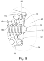
- a spring assembly 10 which comprises two support elements 12 and three coil springs 14. However, only one of the support elements 12 is shown here.
- the coil springs 14 are arranged coaxially or radially within one another as an outer or first coil spring 14a, as a middle or second coil spring 14b and as an inner or third coil spring 14c.
- the coil springs 14 are arranged with their axial end turns on the support elements 12.
- the support element 12 forms a joint section 16, a disc section 18, a step section 20 and a guide section 22.
- steps 24 are formed on the step section 20 of the support element 12.
- a first step 24a is arranged radially on the outside, a second step 24b in the middle and a third step 24c radially on the inside of the support element 12.
- the radial arrangement of the steps 24 corresponds to the radial arrangement of the coil springs 14.
- the first coil spring 14a is assigned to the first step 24a, the second coil spring 14b to the second step 24b and the third coil spring 14c to the third step 24c.
- the steps 24 have contact surfaces 26 which are assigned to control surfaces 28 of the coil springs 14. It can be seen that the steps 24 of the step section 20 and the associated surfaces and configurations are essentially circular, annular or cylindrical.
- intermediate surfaces 30 are formed on the step section 20, which are arranged radially between two contact surfaces 26 each.
- a first intermediate surface 30a is formed between the first contact surface 26a and the second contact surface 26b, the first intermediate surface 30a being assigned to the first coil springs 14a.
- the second and third intermediate surfaces 30b, 30c are both arranged between the second contact surface 26b and the third contact surface 26c.
- the second intermediate surface 30b is assigned to the second coil spring 14b, whereas the third intermediate surface 30c is assigned to the third coil spring 14c.
- the intermediate surfaces 30 simplify the assembly of the spring package and can serve, among other things, to guide the coil springs, in particular when the support elements 12 tilt against each other. This will be explained in more detail below.
- An intermediate surface 30 is advantageously designed axially to be approximately half as long as the wire thickness or winding thickness of the associated helical spring 14.
- the intermediate surfaces 30 can, however, also be designed to be correspondingly longer or shorter.
- the inner intermediate surface 30c is designed to be correspondingly longer due to the step shape, the intermediate surface 30b and the recess 32.
- the intermediate surfaces 30 are also conical. This reduces rubbing or scraping of the coil springs 14 on the intermediate surfaces 30. Contact can even be avoided if necessary. This reduces wear. Such rubbing can occur, for example, when the support elements 12 tilt relative to one another.
- the intermediate surfaces 30 are here tapered by a Angle ⁇ is conical with respect to an axial direction A of the spring assembly 10.
- the axial direction A is parallel to a central axis M of the spring assembly, which extends along the axial direction of the coil springs 14 or from one of the support elements 12 to the other support element 12.
- the central axis M runs centrally or coaxially with the spring assembly 10, in particular coaxially with the coil springs 14.
- the radius of the intermediate surfaces 30 increases or decreases along the central axis of the spring assembly 10, starting from the corresponding support element 12, advantageously continuously, linearly or in another way.
- the intermediate surfaces 30 are inclined or tilted in particular with respect to the central axis M of the support element 12.
- the aforementioned tilting of the support elements 12 with respect to one another can be desired in certain operating states of the torsion damper 40, whereby the angle ⁇ can depend on this. This is explained in more detail below.
- these can be designed as beehive springs.
- the turns that are arranged outside the recess can be expanded radially compared to the turns inside the recess, in particular the end turns.
- the end turns of the coil spring can have a smaller diameter than the remaining turns.
- the steps 24 are formed axially offset from one another on the support element 12, with the second step 24b being arranged higher than the step 24a.
- the support element 12 is axially thicker.
- the third step 24c is, however, recessed compared to the second step 24b.
- a depression 32 or a cutout 32 is formed in particular on the support element 12. This allows the inner coil spring 14c to be made as long as possible.
- the inner coil spring 14c is longer than the middle coil spring 14b and longer than the outer coil spring 14a. This achieves a large spring volume for the inner coil spring 14c.
- the inner coil spring 14c can, however, also be the same length or shorter than the outer coil spring 14a.
- First centering surfaces 34 are also formed on the step section 18 of the support element 12, which interact with second centering surfaces 36 of the coil springs 14.
- the centering surfaces 34, 36 are designed as bevels.
- the first centering surfaces 34 and the second centering surfaces 36 correspond to one another in order to achieve alignment or centering of the coil springs 14 on the support element 12.
- the centering surfaces 34, 36 are conical.
- the second centering surfaces 36 are formed on the coil springs 14 radially inward or radially outward at the ends of the windings.
- the first centering surfaces 34 are arranged on the support element 12 between a contact surface 26 and an intermediate surface 30 or also radially inward or radially outward on a step 24.
- first centering surface 34 of the support element 12 is advantageously the same length or longer than the second centering surface 36 of the coil spring 14.
- the lateral extent of the first centering surface 34 can typically correspond to 10% to 40% of the wire diameter of the coil spring 14.
- the first and second centering surfaces 34 and 36 can be designed such that when the respective coil spring 14 rests against the respective step 24 without force, there is contact between the first and the second centering surface 34, 36.
- the end turn of the respective coil spring 14 can expand or contract radially in order to obtain a contact between the intermediate surfaces 34, 36 as well as the contact surface 24 and the control surface 26. This ensures centering and alignment of the Coil springs 14 on the support element 12 are further improved. It is also possible in principle for the end turns of the coil springs 14 to be radially constricted or radially expanded without preload.
- the first and second centering surfaces 34, 36 can in principle also be implemented on only a partial number of corresponding coil springs 14 and steps 24. Such centering is particularly advantageous on the inner coil spring 14c. This avoids in particular contact between the inner coil spring 14c and the associated inner intermediate surface 30c.
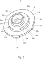
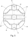
- the support element 12 is again more precisely in the Fig. 3 - 5 shown.
- the support element 12 is preferably designed as a metal part or a steel part and is advantageously manufactured by a cold extrusion process, although other manufacturing methods such as sintering or casting are also conceivable.
- the joint section 16 is essentially designed by semicircular elevations 16 on the support element 12.
- the joint section 16 is divided into several areas by the guide section 22 or the guide sections 22. Each of these areas of the joint section 16 can be assigned to a joint receptacle of an input element or an output element of a torsion damper and can be arranged rotatably on it. Further details on this can be found below.
- the guide section 22 is formed by two elevations 22 on the support element.
- the guide section 22 advantageously engages between the input elements and output elements of a torsion damper.
- the spring assembly is arranged on the torsion damper in a captive manner, particularly when the spring assembly is arranged on the torsion damper in a pre-tensioned manner.
- the guide section reinforces the support element 12. Further details on this will be given below.
- the lateral extension of the guide section 22 and the joint section 16 are formed perpendicular to each other on the surface of the disc section 20.
- disc surfaces 62 are formed on the support element 12, which are arranged next to or between the elevations 16, 22 of the joint section 16 and the guide section 22 on the rear side of the step section 20.
- the disc surfaces 62 are essentially on one plane. Further details on the function of the disc surface 62 are given in the further description.
- the spring package 10 is further into the Fig. 6 - 9 in conjunction with a torsional damper 40 of a clutch disc 38. It should be noted that in the Fig. 8 and Fig. 9 the centering surfaces 34, 36 are not shown. The Fig. 6 - 9 and the further explanations apply in particular to spring assemblies whose support elements 12 have centering surfaces 34, 36.
- the clutch disc 38 has friction linings 42 which are attached to an input element 46 of the torsion damper 40 via lining springs 44.
- the input element 46 is also operatively connected via spring assemblies 10 to two output elements 48 located on either side.
- the output elements 48 are operatively connected to a hub 52 of the clutch disc 38 via a pre-damper 50.
- the following explanations relate mainly to the arrangement and design of the spring assembly 10 on the torsion damper 40 and to its functionality.
- flats 66 are arranged on the support element 10, in particular on the disk section 18.
- the two flats 66 are opposite each other, which enables a directed insertion of the spring assembly 10 into the spring window of a torsion damper.
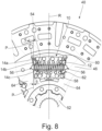
- the Fig. 8 shows the torsion damper 40 in radial section.
- the spring assembly 10 arranged in a spring window 54 of the input element 46 is shown.
- the arrangement of the spring assembly 10 in the corresponding spring windows 54 of the output elements 48 essentially corresponds to the following explanations.
- the spring assembly is pre-tensioned in the spring window 54. Typical pre-tension lengths of the coil springs 14 can be between 1 and 5 mm.
- the spring windows 54 have joint receptacles 56 on their peripheral window surfaces, on which the support elements 12 of the respective spring assembly 10 are arranged.
- the joint section 16 of the respective support element 12 engages in these joint receptacles 56.
- the support element 12 is arranged essentially via the joint section 16 in a form-fitting manner on the spring window 54 and can rotate via the joint section about a pivot point of the joint receptacle 56.
- a rotation of the support element 12 on the spring window 54 is limited by an inner or first window surface 58 and an outer or second window surface 60 of the input element 46 as well as a disk surface 62 of the support element 12.
- the arrangement of the support element on the spring windows 54 is Fig. 8 shown enlarged.
- the first or inner window surface 58 is tilted by an angle ⁇ relative to a line P, parallel, whereby the line P runs parallel to a radial line R, radial.
- the radial line R runs centrally through the corresponding spring window 54.
- This web 64 determines a distance between two adjacent spring windows 54. The widening therefore increases the stability and resistance of the input element 46 and the output elements 48.
- an advantageous control of the spring assembly can be achieved.
- the radially inner areas of the spring ends of the coil springs 14 are in contact with the support elements 12, whereas radially outer areas of the spring ends of the coil spring 14 are axially spaced from the support elements 12.
- radially inner areas of the control surfaces 28 are in contact with their corresponding areas of the contact surfaces 26 in contact, while radially outer regions of the control surfaces 28 are spaced apart from their corresponding regions of the contact surfaces 26 in the circumferential direction.
- the coil springs 14 are more strongly compressed or stressed in the radially inner region of the torsion damper 40 than in the radially outer region of the torsion damper 40.
- a characteristic curve of the torsion damper 40 is very soft at small relative angles of rotation between the input element 46 and the output elements 48. This offers advantages in decoupling torsional vibrations, among other things.
- the spring ends rest completely on the support elements 12, whereby the spring elements 14 are evenly loaded.
- a typical value for the angle ⁇ can be between 1° - 5°.
- the angle ⁇ is advantageously at least the same size or larger than the angle ⁇ .
- the design of the inner window surfaces 58 limits the freedom of movement of the spring assembly 10, in particular of the support elements 12. This can result in the support elements 12 tilting relative to one another.
- a spring assembly 10 can also be installed in the torsion damper 40 in a pre-stressed manner, wherein the spring assembly 10 can be pre-stressed by approximately 1 - 5 mm along a radially inner region of the turns of the outer coil spring 14a.
- the pane surfaces 62 of the support elements 12 can lift off the first window surfaces 58. This can happen, for example, at a relative angle of rotation that is twice as large as the angle ⁇ .
- the support elements can now rotate via their joint sections 16 in the joint receptacles 56, whereby this depends, among other things, on the relative angle of rotation between the input element 46 and the output elements 48.
- the second or outer window surface 60 is tilted by an angle ⁇ relative to a parallel P.
- the second window surface 60 can serve as a stop for the pane surface 62.
- the angle ⁇ is chosen to be large enough that the window surface 62 does not come into contact with the second window surface 60.
- the radially outer coil portions of the coil springs 14 on the torsion damper 40 would be subjected to unevenly greater stress than the radially inner coil portions at maximum compression, which could significantly increase wear.
- the coil spring 14 could bend in such a way that its middle spring coils are pressed radially inwards or bulge radially inwards. The increased wear caused by this could lead to premature breakage of the coil springs 14 and failure of the torsion damper 40.
- the angle ⁇ may typically correspond to 6° - 14°, wherein the angle ⁇ is conveniently greater than half the maximum possible relative angle of rotation between the input element 46 and the output elements 48.
- a maximum relative angle of rotation between the input element 46 and the output elements 48 may typically be between 12° - 28°.
- the torsion damper 40 and the spring assembly 10, in particular their dimensions, are preferably coordinated with one another in such a way that an intermediate surface 30 of the spring assembly at a relative angle of rotation of 0° is longer in the circumferential direction than a radially outer region of the end turn of a coil spring 14 can lift off from the respective contact surface 26.
- the coil springs are thereby securely attached to the torsion damper.
- the coil springs 14 are nevertheless firmly clamped to the spring assembly 10 in a defined position, regardless of this structural design.
- the number of coil springs and steps is chosen here as an example and can have two or more coil springs and steps.
- this design variant with three coil springs and three steps, with the inner step being formed by a recess, is particularly advantageous.
Landscapes
- Engineering & Computer Science (AREA)
- General Engineering & Computer Science (AREA)
- Physics & Mathematics (AREA)
- Acoustics & Sound (AREA)
- Aviation & Aerospace Engineering (AREA)
- Mechanical Engineering (AREA)
- Mechanical Operated Clutches (AREA)
Description
- Die Erfindung betrifft ein Federpaket gemäß dem Oberbegriff des Patentanspruchs 1, sowie einen Torsionsdämpfer mit einem derartigen Federpaket.
- Ein gattungsgemäßes Federpaket ist in der
WO 2006 / 035 173 A1 gezeigt. Dabei umfasst das Federpaket zwei Abstützelemente sowie drei koaxial ineinander angeordnete Schraubenfedern. Die Schraubenfedern weisen hierbei jeweils unterschiedliche Längen, Durchmesser und Drahtdurchmesser auf. Die Abstützelemente bilden weiterhin einen Scheibenabschnitt, einen Gelenkabschnitt sowie einen Stufenabschnitt aus, wobei die Enden der Schraubenfedern an einer jeweiligen Stufe des Stufenabschnitts angeordnet sind. Die Anordnung der Schraubenfedern an den Abstützelementen in lateraler Richtung ist dabei durch Zwischenflächen vorgegeben und eingeschränkt, wobei die Zwischenflächen zwischen den einzelnen Stufen angeordnet sind und den axialen Versatz der Stufen erzeugen. Die Schraubenfedern können sich daher im Betrieb in beschränktem Umfang lateral gegenüber dem Abstützelement bewegen, wodurch die Reibung des Federpakets sowie der Verschleiß des Federpakets erhöht ist. - Zudem ist in der
DE 10 2008 054 190 A1 ein Federpaket mit zwei Schraubenfedern offenbart. Dabei greift eine letzte Windung der inneren Schraubenfeder in eine kreisförmig umlaufende Aussparung ein, um die Abstützelemente an dem Federpaket zu befestigen. Zudem ist ein radial innerer Endbereich der äußeren Schraubenfeder konisch ausgebildet, der ausschließlich an einem konischen Abschnitt des Abstützelements anliegt. - Es ist von dem Stand der Technik ausgehend Aufgabe ein Federpaket bereitzustellen, bei dem die Positionierung der Schraubenfedern an den Abstützelementen verbessert ist und die Reibung des Federpaket sowie der Verschleiß verringert ist.
- Diese Aufgabe wird durch ein Federpaket mit den Merkmalen des Patentanspruchs 1 gelöst. In den abhängigen Ansprüchen sind vorteilhafte Ausführungen der Erfindung beschrieben.
- Das Federpaket umfasst daher zumindest eine Schraubenfeder an deren axialen Enden Abstützelemente, auch Federteller genannt, angeordnet sind. An dem Abstützelement sind dabei vorzugsweise ein Scheibenabschnitt, ein Gelenkabschnitt, ein Stufenabschnitt und / oder ein Führungsabschnitt ausgebildet. Der Gelenkabschnitt, der Scheibenabschnitt und der Führungsabschnitt können dabei der Ansteuerung des Federpakets durch Federfenster eines Torsionsdämpfers dienen. Der Stufenabschnitt dient vorzugsweise der Ansteuerung der Schraubenfeder und kann als Ansteuerabschnitt für die Schraubenfeder ausgebildet sein. Dabei ist die Schraubenfeder günstigerweise an einer Stufe des Abstützelements angeordnet. Dabei kann eine in lateraler Richtung ausgebildete Fläche der Stufe als Anlagefläche für eine Ansteuerfläche des Federelements dienen. Zudem kann eine in axialer Richtung ausgebildete Fläche eine laterale Beweglichkeit der Schraubenfeder gegenüber dem Abstützelement begrenzen. Der Scheibenabschnitt, insbesondere der dem Ansteuerabschnitt gegenüberliegende Anteil davon, kann zudem als Abstützabschnitt für ein Funktionselement, insbesondere für ein Eingangselement und / oder ein Ausgangselement eines Torsionsdämpfers, dienen.
- An dem Abstützelement, insbesondere an der Stufe des Stufenabschnitts, ist eine erste Zentrierfläche ausgebildet, die mit einer zweiten Zentrierfläche der Schraubenfeder korrespondiert und zusammenwirkt, um die Schraubenfeder an dem Federpaket auszurichten, insbesondere zu zentrieren. Die erste Zentrierfläche ist dabei an einem lateralen Endbereich der Anlagefläche ausgebildet, beispielsweise zwischen der Anlagefläche der Stufe und einer Zwischenfläche.
- Im Vergleich mit den bekannten Ausführungen kann eine unerwünschte Beweglichkeit der Schraubenfeder gegenüber dem Abstützelement verringert oder auch vermieden werden. Eine laterale Ausrichtung der Schraubenfeder an dem Abstützelement kann hierdurch weiter verbessert werden. Die erste und die zweite Zentrierfläche sind dabei konisch ausgebildet. Die Zwischenfläche bildet hierbei den axialen Versatz an dem Stufenabschnitt aus.
- Die Zentrierflächen sorgen dabei für eine definierte Anordnung der Schraubenfeder an den Abstützelementen des Federpakets. Insbesondere bei Verwendung mehrerer Schraubenfedern können Abstände zwischen den Federelementen, auch während des Betriebs, sicher vorgegeben werden, wodurch insbesondere Verschleiß durch Reiben oder Schaben der Windungen der Schraubenfedern aneinander vermieden werden kann.
- Erfindungsgemäß liegt in entspanntem Zustand des Federpakets die zweite Zentrierfläche der Schraubenfeder an der ersten Zentrierfläche der Stufe des Abstützelements an und die Ansteuerfläche der Schraubenfeder und die zugehörige Anlagefläche der Stufe weisen einen axialen Abstand auf.
- Die Ausrichtung der Schraubenfeder an dem Abstützelement durch die Zentrierflächen ist hierdurch sichergestellt. In entspanntem Zustand liegen die Schraubenfeder und das Abstützelement kraftfrei, also ohne vorspannende Kräfte, aneinander an.
- Günstigerweise liegt in gespanntem Zustand des Federpakets die zweite Zentrierfläche der Schraubenfeder an der ersten Zentrierfläche der Stufe des Abstützelements an und / oder die Ansteuerfläche der Schraubenfeder und die zugehörige Anlagefläche der Stufe liegen aneinander an.
- In gespanntem Zustand wirkt effektiv eine axiale Kraft auf die axialen Enden des Federpakets, insbesondere auf die Abstützelemente, wodurch die Federenden der Schraubenfeder an das Abstützelement gedrückt werden. In gespanntem Zustand ist das Federpaket gegenüber dem entspannten Zustand bereits um eine bestimmte Länge komprimiert. Hierdurch kann der bereits oben erwähnte axiale Abstand zwischen der Ansteuerfläche und der Anlagefläche verringert werden, insbesondere verschwinden. Zudem liegen die erste Zentrierfläche und die zweite Zentrierfläche aneinander an. Hierdurch kann eine optimale Krafteinleitung in die Schraubenfeder erreicht werden. Zudem ist die Schraubenfeder fest an dem Abstützelement ausgerichtet, insbesondere in lateraler und in axialer Richtung.
- Mit Vorteil ist in gespanntem Zustand des Federpakets eine axiale Endwindung der Schraubenfeder radial gegenüber den anderen Windungen der Schraubenfeder radial aufgeweitet oder radial verringert, insbesondere durch Verformung aufgrund einer, das Federpaket, vorspannenden effektiven Kraft.
- Da die Schraubenfeder mit einer Axialkraft gegenüber dem Abstützelement beaufschlagt wird, kann sich das Federende aufgrund der Zentrierflächen, insbesondere konischer Zentrierflächen, radial aufweiten oder radial verringern oder einengen. Dieses radiale aufweiten oder radiale verringern entspricht im Wesentlichen einer Verformung der Schraubenfeder aufgrund der wirkenden effektiven Kraft. Dies kann sich auf die Endwindungen oder die Endwindung des Federelements beschränken. Die laterale Festlegung der Schraubenfeder an dem Abstützelement wird hierdurch nochmals verbessert. Die laterale Verformung der Schraubenfeder ist dabei abhängig von der Ausführung der Zentrierflächen sowie der Schraubenfeder und dem Abstützelement. Die Schraubenfeder kann zudem auch derart ausgebildet sein, dass deren Endwindung bereits radial voraufgeweitet oder radial voreingeengt ist, insbesondere bei einer nicht vorhandenen effektiven Kraft.
- In einer Ausführungsvariante sind an dem Federpaket zumindest zwei Schraubenfedern ausgebildet, die radial oder koaxial ineinander angeordnet, wobei die radial innere Schraubenfeder in einer Vertiefung oder Ausnehmung des Abstützelements angeordnet ist.
- Durch die Verwendung mehrerer Schraubenfedern an einem Federpaket kann bei unveränderter Federkraft des Federpakets ein längerer Federweg erreicht werden. Alternativ kann bei gleichem Federweg eine höhere Federkraft erreicht werden. Dies ist dadurch begründet, dass bei Verwendung zusätzlicher Schraubenfedern die Drahtstärke der einzelnen Schraubenfedern verringert werden kann, wodurch sich die einzelnen Windungen erst bei längeren Federwegen aneinander anlegen und die Schraubenfeder auf Block geht. Durch die radiale und / oder koaxiale Anordnung der Schraubenfedern ineinander ist eine kompakte Anordnung möglich. Zudem kann eine radial innere Schraubenfeder durch die Anordnung in einer Vertiefung oder einer Ausnehmung an dem Abstützelement, insbesondere an dem Stufenabschnitt, besonders lang ausgebildet werden, wodurch für die innere Schraubenfeder ein langer Federweg und damit auch ein großes Federvolumen bereitgestellt wird.
- Die Vertiefung ist günstigerweise mittig oder zentriert an dem Stufenbereich des Abstützelements ausgebildet. Der Stufenabschnitt kann dabei mehrere radial zueinander angeordnete Stufen ausbilden, wobei vorzugsweise die innerste Stufe durch die Vertiefung ausgebildet ist. Diese Vertiefung ist besonders bei Verwendung von drei Federelementen von Vorteil, da die innere Schraubenfeder länger ausgebildet werden kann als zumindest eine weitere Schraubenfeder. Bei Verwendung eines derartigen Federpakets mit drei Schraubenfedern in einem Torsionsdämpfer kann eine Verdrehsteifigkeit um etwa 10% verringert werden.
- Mit besonderem Vorteil ist die radial innerste Schraubenfeder gleich lang oder länger als eine weitere Schraubenfeder des Federpakets ausgebildet.
- Wie bereits oben erwähnt, kann durch eine lang ausgebildete radial innere Schraubenfeder eine Verdrehsteifigkeit eines Torsionsdämpfer mit einem solchen Federpaket weiter verringert werden. Die radial innerste Schraubenfeder, die in der Vertiefung angeordnet sein kann, ist dabei günstigerweise gleich lang oder länger ausgebildet als die radial äußerste Schraubenfeder. Bei der Verwendung des Stufenabschnitts an dem Abstützelement zur Ansteuerung der Schraubenfedern ist es üblich, dass sich die Federlänge von den radial außenliegenden Schraubenfedern zu den radial innenliegenden Schraubenfedern verkürzt. Die Vertiefung ermöglicht es allerdings innere Schraubenfedern relativ lang auszubilden.
- In einer Ausführungsvariante ist eine Zwischenfläche, die zwischen zwei Anlageflächen angeordnet ist und einen axialen Versatz der Stufen ausbildet, konisch ausgebildet.
- Durch die konische Ausführung der Zwischenfläche kann ein Reiben der Schraubenfeder an der Zwischenfläche nochmals weiter reduziert oder sogar verhindert werden. Derartiges Reiben entsteht insbesondere dann, wenn eine Bewegungsfreiheit des Federpakets, insbesondere der Abstützelemente eingeschränkt ist. Ein Winkel der konisch ausgeführten Zwischenfläche steht daher günstigerweise in Zusammenhang mit der Einschränkung der Bewegungsfreiheit der Abstützelemente. Dies wird in der Figurenbeschreibung nochmals ausführlicher erläutert.
- Es wird weiter ein Torsionsdämpfer gemäß den Merkmalen des Patentanspruchs 8-7 vorgeschlagen, der ein Federpaket nach zumindest einer der obigen Ausführungen oder nach einem der Ansprüche 1 bis 6 umfasst.
- Der Torsionsdämpfer wird günstigerweise in einer Kupplungsscheibe verwendet und kann entsprechend den bekannten Ausführungen ausgebildet sein. Dabei umfasst der Torsionsdämpfer günstigerweise ein scheibenförmiges Eingangselement und ein scheibenförmiges Ausgangselement, die drehbar zueinander um eine Rotationsachse angeordnet sind. Das Eingangselement und das Ausgangselement sind dabei günstigerweise über zumindest ein Federpaket miteinander wirkverbunden, wobei das Federpaket günstigerweise in Federfenstern des Eingangselements und des Ausgangselements angeordnet ist. Das Federpaket ist dabei mit Vorzug gemäß zumindest einer der vorigen Ausführungen ausgebildet.
- Wie bereits erwähnt, kann hierdurch der Verschleiß der Federpakete verringert werden und die Effizienz verbessert werden. Zudem kann durch die Verringerung der Verdrehsteifigkeit des Torsionsdämpfers entweder ein größeres Motormoment übertragen oder eine Drehentkopplung zwischen einem Motor und einem Antriebsstrang verbessert werden.
- Torsionsdämpfer nach Anspruch 8, dadurch gekennzeichnet, dass das Federpaket vorgespannt in Federfenstern des Eingangselement und des Ausgangselements angeordnet ist.
- Durch die Vorspannung des Federpakets, beispielsweise um 1 bis 5 mm Federweg, sind die Schraubenfedern zentriert und fest an dem Federpaket angeordnet. Diese definierte Anordnung der Schraubenfedern untereinander und gegenüber dem Abstützelement ist daher auch bei 0° Relativdrehwinkel zwischen dem Eingangselement und dem Ausgangselement gegeben. Zudem bleibt das Federpaket bei einem Überdrehen von 0° Relativdrehwinkel fest in seiner definierten Position, wobei insbesondere die Anordnung der Schraubenfedern untereinander dauerhaft festgelegt ist und unverändert bleibt.
- In einer weiteren vorteilhaften Ausführungsvariante sind bis zum Erreichen eines definierten Relativdrehwinkels zwischen dem Eingangselement und dem Ausgangselement radial innenliegende Windungsanteile stärker gespannt als radial außenliegende Windungsanteile der Schraubenfeder.
- Dabei kann ein radial innenliegender Bereich einer Endwindung der Schraubenfeder an dem Abstützelement in Anlagekontakt anliegen, wobei ein radial außenliegender Anteil der Endwindung der Schraubenfeder von dem Abstützelement axial beabstandet ist, insbesondere die Ansteuerfläche der Schraubenfeder von der Anlagefläche des Abstützelements beabstandet ist. Radial innen- und außenliegende Bereiche beziehen sich hierbei auf die Ausdehnungen des Torsionsdämpfers und nicht auf die des Federpakets selbst. Durch die Vorspannung der radial innenliegenden Windungsanteile sind die Schraubenfedern fest an dem Federpaket positioniert und ebenso gegeneinander ausgerichtet. Zudem wird bei geringen Relativdrehwinkeln des Torsionsdämpfers eine sehr flache, langsam ansteigende Kennlinie erreicht. Dabei wirken zunächst nur die radial innenliegenden Windungsanteile der Schraubenfedern, deren effektiver Wirkradius einen geringen Abstand zur Drehachse des Torsionsdämpfers bildet. Die radial außenliegenden Windungsanteile können als zumindest teilweise entlastet betrachtet werden. Mit steigendem Relativdrehwinkel des Torsionsdämpfers legen sich die Endwindungen der Schraubenfedern, insbesondere deren radial außenliegenden Bereiche der Windungsenden, an den Abstützelementen an, wodurch die Schraubenfedern gleichmäßig belastet sind. Dabei verschiebt sich der effektiver Wirkradius des Federpakets radial nach außen.
- Eine derartige Ansteuerung der Schraubenfedern kann beispielsweise durch eine bestimmte Ausbildung der Federfenster des Torsionsdämpfers und des Abstützelements erreicht werden, welche in der Figurenbeschreibung ausführlicher erläutert wird.
- Es wird daher vorgeschlagen, dass bis zum Erreichen eines definierten Relativdrehwinkels zwischen dem Eingangselement und dem Ausgangselement radial innenliegende Bereiche der Ansteuerfläche der Schraubenfeder und der Anlagefläche des Abstützelements in Anlagekontakt stehen und radial außenliegende Bereiche der Ansteuerfläche der Feder und der Anlagefläche des Abstützelements voneinander beabstandet sind.
- Hierzu können die zuvor erläuterten Ausführungen herangezogen werden.
- Das erfindungsgemäße Federpaket und der erfindungsgemäße Torsionsdämpfer werden im Folgenden anhand der beigefügten Figuren beispielhaft erläutert. Hierbei zeigen:
- Fig. 1
- ein Federpaket mit Schraubenfedern und einem Abstützelement;
- Fig. 2
- ein vergrößerte Teilansicht des Federpakets aus
Fig. 1 ; - Fig. 3
- eine perspektivische Ansicht des Abstützelements aus
Fig. 1 ; - Fig. 4
- eine weitere perspektivische Ansicht des Abstützelements aus
Fig. 1 ; - Fig. 5
- eine weitere Ansicht des Abstützelements aus
Fig. 1 ; - Fig. 6
- eine Teildarstellung einer Kupplungsscheibe mit einem Torsionsdämp-fer und Federpaketen;
- Fig. 7
- eine Schnittansicht der Kupplungsscheibe aus
Fig. 6 ; - Fig. 8
- eine Schnittansicht des Torsionsdämpfer aus
Fig. 6 ; - Fig. 9
- einen vergrößerten Ausschnitt des Torsionsdämpfers aus
Fig. 8 . - In den
Fig. 1 und Fig. 2 ist ein Federpaket 10 dargestellt, welches zwei Abstützelemente 12 sowie drei Schraubenfedern 14 umfasst. Hierbei ist jedoch nur eines der Abstützelemente 12 dargestellt. Die Schraubenfedern 14 sind dabei koaxial bzw. radial ineinander als äußere oder erste Schraubenfeder 14a, als mittlere oder zweite Schraubenfeder 14b und als innere oder dritte Schraubenfeder 14c angeordnet. Dabei sind die Schraubenfedern 14 mit deren axialen Endwindungen an den Abstützelementen 12 angeordnet. - Das Abstützelement 12 bildet hierbei einen Gelenkabschnitt 16, einen Scheibenabschnitt 18, einen Stufenabschnitt 20 und einen Führungsabschnitt 22 aus. Dabei sind an dem Stufenabschnitt 20 des Abstützelements 12 mehrere Stufen 24 ausgeführt. Eine erste Stufe 24a ist dabei radial außen, eine zweite Stufe 24b in der Mitte und eine dritte Stufe 24c radial innen an dem Abstützelement 12 angeordnet. Die radiale Anordnung der Stufen 24 entspricht hierbei der radialen Anordnung der Schraubenfedern 14. Dabei ist die erste Schraubenfeder 14a der ersten Stufe 24a, die zweite Schraubenfeder 14b der zweiten Stufe 24b und die dritte Schraubenfeder 14c der dritten Stufe 24c zugeordnet. Die Stufen 24 weisen hierbei Anlageflächen 26 auf, die Ansteuerflächen 28 der Schraubenfedern 14 zugeordnet sind. Man erkennt, dass die Stufen 24 des Stufenabschnitts 20 sowie die zugehörigen Flächen und Ausgestaltungen im Wesentlichen kreisförmig, ringförmig oder zylinderförmig ausgebildet sind.
- Zum Erhalt eines axialen Versatzes der Anlageflächen 26 sind an dem Stufenabschnitt 20 Zwischenflächen 30 ausgebildet, die radial zwischen je zwei Anlageflächen 26 angeordnet sind. Eine erste Zwischenfläche 30a ist dabei zwischen der ersten Anlagefläche 26a und der zweiten Anlagefläche 26b ausgebildet, wobei die erste Zwischenfläche 30a der ersten Schraubenfedern 14a zugeordnet ist. Die zweite und die dritte Zwischenfläche 30b, 30c sind beide zwischen der zweiten Anlagefläche 26b und der dritten Anlagefläche 26c angeordnet. Dabei ist die zweite Zwischenfläche 30b der zweiten Schraubenfeder 14b zugewiesen, wohingegen die dritte Zwischenfläche 30c der dritten Schraubenfeder 14c zugewiesen ist. Die Zwischenflächen 30 vereinfachen den Zusammenbau des Federpakets und können unter anderem der Führung der Schraubenfedern dienen, insbesondere wenn die Abstützelemente 12 gegeneinander verkippen. Dies wird im Folgenden noch ausführlicher ausgeführt. Eine Zwischenfläche 30 ist axial günstigerweise in etwa halb so lang ausgebildet wie die Drahtdicke oder auch Windungsdicke der zugehörigen Schraubenfeder 14. Die Zwischenflächen 30 können allerdings auch entsprechend länger oder kürzer ausgebildet sein. Die innere Zwischenfläche 30c ist, bedingt durch die Stufenform, die Zwischenfläche 30b und die Vertiefung 32, entsprechend länger ausgeführt.
- Die Zwischenflächen 30 sind hierbei zudem konisch ausgebildet. Dies verringert ein Reiben oder ein Schaben der Schraubenfedern 14 an den Zwischenflächen 30. Gegebenenfalls kann sogar ein Kontakt vermieden werden. Ein Verschleiß wird hierdurch reduziert. Ein derartiges Reiben kann beispielsweise bei Verkippen der Abstützelemente 12 zueinander auftreten. Die Zwischenflächen 30 sind hier um einen Winkel α gegenüber einer Axialrichtung A des Federpakets 10 konisch ausgeführt. Die Axialrichtung A ist dabei parallel zu einer Mittelachse M des Federpakets, die sich entlang der einer Axialrichtung der Schraubenfedern 14 oder von einem der Abstützelemente 12 zu dem anderen Abstützelement 12 erstreckt. Dabei verläuft die Mittelachse M mittig an oder koaxial zu dem Federpaket 10, insbesondere koaxial zu den Schraubenfedern 14. Der Radius der Zwischenflächen 30 nimmt entlang der Mittelachse des Federpakets 10, ausgehend von dem entsprechenden Abstützelement 12, ab oder zu, günstigerweise kontinuierlich, linear oder auf andere Art und Weise. Die Zwischenflächen 30 sind dabei insbesondere gegenüber der Mittelachse M des Abstützelements 12 geneigt oder gekippt. Das erwähnte Verkippen der Abstützelemente 12 zueinander kann bei bestimmten Betriebszuständen des Torsionsdämpfers 40 gewünscht sein, wobei der Winkel α hiervon abhängen kann. Dies wird im Folgenden noch ausführlicher erläutert.
- Um ein Federvolumen der inneren Schraubenfedern 14c weiter zu vergrößern, kann diese als Bienenkorbfeder ausgeführt sein. Hierbei können die Windungen, die außerhalb der Vertiefung angeordnet sind, radial gegenüber den Windungen innerhalb der Vertiefung, insbesondere den Endwindungen, aufgeweitet sein. Insbesondere können die Endwindungen der Schraubenfeder einen kleineren Durchmesser aufweisen als die restlichen Windungen.
- Die Stufen 24 sind an dem Abstützelement 12 axial versetzt zueinander ausgebildet, wobei die zweite Stufe 24b gegenüber der Stufe 24a erhöht angeordnet ist. In dem Bereich der zweiten Stufe 24b ist das Abstützelement 12 axial dicker ausgeführt. Die Dritte Stufe 24c ist gegenüber der zweiten Stufe 24b jedoch vertieft ausgebildet. Dafür ist an dem Abstützelement 12 insbesondere eine Vertiefung 32 oder eine Ausnehmung 32 ausgeführt. Hierdurch kann die innere Schraubenfeder 14c möglichst lang ausgebildet werden. Dabei ist die innere Schraubenfeder 14c länger als die mittlere Schraubenfeder 14b ausgeführt und länger als die äußere Schraubenfeder 14a. Dadurch wird für die innere Schraubenfeder 14c ein großes Federvolumen erreicht. Die innere Schraubenfeder 14c kann allerdings auch gleich lang oder kürzer als die äußere Schraubenfeder 14a ausgeführt sein.
- An dem Stufenabschnitt 18 des Abstützelements 12 sind zudem erste Zentrierflächen 34 ausgebildet, die mit zweiten Zentrierflächen 36 der Schraubenfedern 14 zusammenwirken. Die Zentrierflächen 34, 36 sind dabei als Fasen ausgeführt. Die ersten Zentrierflächen 34 und die zweiten Zentrierflächen 36 korrespondieren miteinander, um eine Ausrichtung oder auch Zentrierung der Schraubenfedern 14 an dem Abstützelement 12 zu erreichen. Dabei sind die Zentrierflächen 34, 36 konisch ausgeführt. An den Schraubenfedern 14 sind die zweiten Zentrierflächen 36 radial innen oder radial außen an den Windungsenden ausgebildet. Die ersten Zentrierflächen 34 sind an dem Abstützelement 12 jeweils zwischen einer Anlagefläche 26 und einer Zwischenfläche 30 angeordnet oder auch radial innen oder radial außen an einer Stufe 24.
- Zudem sind der Winkel sowie die Länge der konisch ausgeführten ersten und zweiten Zentrierflächen 34, 36 aufeinander abgestimmt. Hierbei ist die erste Zentrierfläche 34 des Abstützelements 12 günstigerweise gleich lang oder länger als die zweite Zentrierfläche 36 der Schraubenfeder 14. Dabei kann die laterale Ausdehnung der ersten Zentrierfläche 34 typischerweise 10% bis 40% des Drahtdurchmessers der Schraubenfeder 14 entsprechen.
- Die ersten und zweiten Zentrierflächen 34 und 36 können dabei derart ausgebildet sein, dass bei kraftloser Anlage der jeweiligen Schraubenfeder 14 an der jeweiligen Stufe 24 ein Anlagekontakt zwischen der ersten und der zweiten Zentrierfläche 34, 36 besteht.
- Bei kraftloser Anlage der Schraubenfedern 14 an der jeweiligen Stufe 24 stehen die erste Zentrierfläche 34 und die zweite Zentrierfläche 36 in Anlagekontakt und die jeweilige Anlagefläche 26 weist einen axialen Abstand zu der Ansteuerfläche 26 aufweist. Dies ist in der
Fig. 2 dargestellt. Durch Vorspannen oder komprimieren des Federpakets 10 kann sich die Endwindung der jeweiligen Schraubenfeder 14 radial aufweiten oder radial einengen um einen Anlagekontakt der Zwischenflächen 34, 36 sowie der Anlagefläche 24 und der Ansteuerfläche 26 zu erhalten. Hierdurch wird eine Zentrierung und Ausrichtung der Schraubenfedern 14 an dem Abstützelement 12 nochmals verbessert. Es ist grundsätzlich auch möglich, dass die Endwindungen der Schraubenfedern 14 ohne Vorspannung bereits radial eingeengt oder radial aufgeweitet ausgeführt sind. - Die ersten und zweiten Zentrierflächen 34, 36 können grundsätzlich auch nur an einer Teilanzahl korrespondierender Schraubenfedern 14 und Stufen 24 ausgeführt werden. Dabei ist eine derartige Zentrierung besonders an der inneren Schraubenfeder 14c mit Vorteilen verbunden. Hierdurch wird insbesondere ein Kontakt zwischen der inneren Schraubenfeder 14c und der zugehörigen inneren Zwischenfläche 30c vermieden.
- Das Abstützelement 12 ist nochmals genauer in den
Fig. 3 - 5 dargestellt. Das Abstützelement 12 ist dabei vorzugsweise als Metallteil oder auch Stahlteil ausgebildet und günstigerweise durch ein kaltfließpressendes Verfahren hergestellt, wobei auch andere Herstellungsmethoden wie beispielsweise sintern oder auch Guss denkbar sind. Man erkennt, dass der Gelenkabschnitt 16 im Wesentlichen durch halbkreisförmige Erhöhungen 16 an dem Abstützelement 12 ausgeführt ist. Dabei ist der Gelenkabschnitt 16 durch den Führungsabschnitt 22 oder auch die Führungsabschnitte 22 in mehrere Bereiche unterteilt. Jeder dieser Bereiche des Gelenkabschnitts 16 kann einer Gelenkaufnahme eines Eingangselements oder eines Ausgangselements eines Torsionsdämpfers zugeordnet und drehbar an diesem angeordnet sein. Weitere Ausführungen hierzu sind im Folgenden zu finden. - Der Führungsabschnitt 22 wird hierbei durch zwei Erhöhungen 22 an dem Abstützelement gebildet. Der Führungsabschnitt 22 greift günstigerweise zwischen den Eingangselementen und Ausgangselementen eines Torsionsdämpfer ein. Hierdurch ist das Federpaket verliersicher an dem Torsionsdämpfer angeordnet, insbesondere wenn das Federpaket vorgespannt an dem Torsionsdämpfer angeordnet ist. Zudem verstärkt der Führungsabschnitt das Abstützelement 12. Ausführungen hierzu werden im Weiteren gemacht.
- Die laterale Ausdehnung von Führungsabschnitt 22 und Gelenkabschnitt 16 zueinander sind an der Oberfläche des Scheibenabschnitts 20 senkrecht zueinander ausgebildet.
- An dem Abstützelement 12 sind zudem Scheibenflächen 62 ausgebildet, die neben oder zwischen den Erhöhungen 16, 22 des Gelenkabschnitts 16 und des Führungsabschnitts 22 rückseitig des Stufenabschnitts 20 angeordnet sind. Die Scheibenflächen 62 liegen hierbei im Wesentlichen auf einer Ebene. Weitere Ausführungen zur Funktion der Scheibenfläche 62 werden in der weiteren Beschreibung gegeben.
- Das Federpaket 10 ist weiter in den
Fig. 6 - 9 in Verbindung mit einem Torsionsdämpfer 40 einer Kupplungsscheibe 38 gezeigt. Es ist zu beachten, dass in derFig. 8 undFig. 9 die Zentrierflächen 34, 36 nicht dargestellt sind. DieFig. 6 - 9 und die weiteren Ausführungen gelten allerdings im Besonderen auch für Federpakete, deren Abstützelemente 12 Zentrierflächen 34, 36 aufweisen. Dabei weist die Kupplungsscheibe 38 Reibbeläge 42 auf, die über Belagfedern 44 an einem Eingangselement 46 des Torsionsdämpfers 40 befestigt sind. Das Eingangselement 46 ist weiter über Federpakete 10 mit zwei beidseitig dazu befindlichen Ausgangselementen 48 wirkverbunden. Dabei sind die Ausgangselemente 48 über einen Vordämpfer 50 mit einer Nabe 52 der Kupplungsscheibe 38 wirkverbunden. Die folgenden Ausführungen beziehen sich hauptsächlich auf die Anordnung und Ausführung des Federpakets 10 an dem Torsionsdämpfer 40 sowie auf dessen Funktionsweise. - Es ist zu beachten, dass sich die räumlichen Beziehungen, wie radial, lateral, in Umfangsrichtung usw. im Folgenden nicht mehr auf das Federpaket 10 beziehen, sondern nunmehr auf den Torsionsdämpfer 38.
- Zudem sind an dem Abstützelement 10, insbesondere an dem Scheibenabschnitt 18, Abflachungen 66 angeordnet. Dabei liegen sich die beiden Abflachen 66 gegenüber, wodurch ein gerichtetes Einsetzen des Federpakets 10 in die Federfenster eines Torsionsdämpfers ermöglicht wird.
- Die
Fig. 8 zeigt den Torsionsdämpfer 40 im Radialschnitt. Dabei ist unter anderem das in einem Federfenster 54 des Eingangselements 46 angeordnete Federpaket 10 dargestellt. Die Anordnung des Federpakets 10 in den entsprechenden Federfenstern 54 der Ausgangselemente 48 stimmt mit den nachfolgenden Ausführungen im Wesentlichen übereinstimmen. Das Federpaket ist dabei vorgespannt in dem Federfenster 54 angeordnet. Typische Vorspannlängen der Schraubenfedern 14 können zwischen 1 bis 5 mm liegen. - Dabei weisen die Federfenster 54 an deren umfangseitigen Fensterflächen, an denen die Abstützelemente 12 des jeweiligen Federpakets 10 angeordnet ist, Gelenkaufnahmen 56 auf. In diese Gelenkaufnahmen 56 greift der Gelenkabschnitt 16 des jeweiligen Abstützelements 12 ein. Das Abstützelement 12 ist dabei im Wesentlichen über den Gelenkabschnitt 16 formschlüssig an dem Federfester 54 angeordnet und kann sich über den Gelenkabschnitt um einen Drehpunkt der Gelenkaufnahme 56 drehen. Ein Verdrehen des Abstützelements 12 an dem Federfenster 54 ist hierbei über eine innere oder erste Fensterfläche 58 und eine äußere oder zweite Fensterfläche 60 des Eingangselements 46 sowie eine Scheibenfläche 62 des Abstützelements 12 begrenzt. In der
Fig. 9 ist die Anordnung des Abstützelements an den Federfenstern 54 ausFig. 8 vergrößert dargestellt. - Die erste oder auch innere Fensterfläche 58 ist gegenüber einer Linie P, Parallele, um einen Winkel β verkippt, wobei die Linie P parallel zu einer radial verlaufenden Line R, Radiale, verläuft. Die radiale Linie R verläuft hierbei mittig durch das entsprechende Federfenster 54. Hierdurch ist ein Steg 64 des Eingangselements 46 verbreitert. Dieser Steg 64 bestimmt einen Abstand zwischen zwei benachbarten Federfenstern 54. Die Verbreiterung erhöht daher die Stabilität und Widerstandsfähigkeit des Eingangselements 46 und der Ausgangselemente 48. Zudem kann eine vorteilhafte Ansteuerung des Federpakets erreicht werden. In der
Fig. 8 erkennt man, dass die radial innenliegende Bereiche der Federenden der Schraubenfedern 14 mit den Abstützelementen 12 in Anlagekontakt stehen, wohingegen radial außenliegende Bereiche der Federenden der Schraubenfeder 14 axial beabstandet zu den Abstützelementen 12 sind. Mit anderen Worten sind radial innenliegende Bereiche der Ansteuerflächen 28 zu deren korrespondierenden Bereichen der Anlageflächen 26 in Anlagekontakt, während radial außenliegende Bereiche der Ansteuerflächen 28 mit deren korrespondieren Bereichen der Anlageflächen 26 in Umfangsrichtung einen Abstand aufweisen. Zudem sind die Schraubenfedern 14 in dem radial inneren Bereich des Torsionsdämpfers 40 stärker komprimiert oder beansprucht als in dem radial äußeren Bereich des Torsionsdämpfers 40. - Hierdurch ist eine Kennlinie des Torsionsdämpfers 40 bei geringen Relativdrehwinkeln zwischen dem Eingangselement 46 und den Ausgangselementen 48 sehr weich. Dies bietet unter anderem Vorteile bei der Entkopplung von Drehschwingungen. Mit steigendem Relativdrehwinkel, insbesondere ab doppeltem Winkel β, legen sich die Federenden vollständig an den Abstützelementen 12 an, wodurch die Federelemente 14 gleichmäßig belastet werden. Ein typischer Wert für den Winkel β kann zwischen 1° - 5° liegen. Mit Vorteil ist der Winkel α zumindest gleich groß oder größer als der Winkel β ausgebildet. Durch die Ausbildung der inneren Fensterflächen 58 ist die Bewegungsfreiheit des Federpakets 10, insbesondere der Abstützelemente 12, eingeschränkt. Hierdurch kann sich ein Verkippen der Abstützelemente 12 zueinander ergeben.
- Bei einer derartigen Ausführung der Federfenster 54 kann ein Federpaket 10 ebenfalls vorgespannt in den Torsionsdämpfer 40 eingebaut werden, wobei hier das Federpaket 10 entlang einem radial inneren Bereich der Windungen äußeren Schraubenfeder 14a um etwa 1 - 5 mm vorgespannt sein kann.
- Mit steigendem Vedrehwinkel können sich die Scheibenflächen 62 der Abstützelemente 12 von den ersten Fensterflächen 58 abheben. Dies kann beispielsweise bei einem Relativdrehwinkel geschehen, der doppelt so groß ist wie der Winkel β. Die Abstützelemente können sich nun über deren Gelenkabschnitte 16 in den Gelenkaufnahmen 56 drehen, wobei dies unter anderem von dem Relativdrehwinkel zwischen Eingangselement 46 und den Ausgangselementen 48 abhängt.
- Die zweite oder auch äußere Fensterfläche 60 ist gegenüber einer Parallele P um einen Winkel ϕ verkippt. Dabei kann die zweite Fensterfläche 60 als Anschlag für die Scheibenfläche 62 dienen. Günstigerweise ist der Winkel ϕ derart groß gewählt, dass die Scheibenfläche 62 nicht in Anlagekontakt mit der zweiten Fensterfläche 60 kommt. Bei einem derartigen Anlagekontakt würden die an dem Torsionsdämpfer 40 radial außenliegenden Windungsanteile der Schraubenfedern 14 bei maximaler Kompression ungleichmäßig stärker belastet werden als die radial innenliegenden Windungsanteile, wodurch ein Verschleiß wesentlich erhöht sein kann. Zudem könnte die Schraubenfeder 14 sich derart verbiegen, dass deren mittlere Federwindungen nach radial innen gedrückt werden bzw. nach radial innen bauchen. Durch den hierdurch erhöhten Verschleiß kann es zu einem frühen Bruch der Schraubenfedern 14 und zu einem Ausfall des Torsionsdämpfers 40 kommen.
- Der Winkel ϕ kann typischerweise 6° - 14° entsprechen, wobei der Winkel ϕ günstigerweise größer ist als die Hälfte des maximal möglichen Relativdrehwinkels zwischen dem Eingangselement 46 und den Ausgangselementen 48. Ein maximaler Relativdrehwinkel zwischen dem Eingangselement 46 und den Ausgangselementen 48 kann typischerweise zwischen 12° - 28° liegen.
- Der Torsionsdämpfer 40 und das Federpaket 10, insbesondere deren Abmessungen, sind dabei vorzugsweise derart aufeinander abgestimmt, dass eine Zwischenfläche 30 des Federpakets bei 0° Relativdrehwinkel in Umfangsrichtung länger ausgeführt ist, als sich ein radial außenliegender Bereich der Endwindung einer Schraubenfeder 14 von der jeweiligen Anlagefläche 26 abheben kann. Die Schraubenfedern sind hierdurch verliersicher an dem Torsionsdämpfer festgelegt. Bei 0° Relativdrehwinkel des Torsionsdämpfers 40 sind die Schraubenfedern 14 unabhängig von dieser konstruktiven Ausführung dennoch fest und mit definierter Position an dem Federpaket 10 eingespannt.
- Die Anzahl der Schraubenfedern und der Stufen ist hier beispielhaft gewählt und kann zwei oder mehr Schraubenfedern und Stufen aufweisen. Diese Ausführungsvariante mit drei Schraubenfedern und drei Stufen, wobei die innere Stufe durch eine Vertiefung ausgebildet ist, ist jedoch besonders vorteilhaft.
-
- 10
- Federpaket
- 12
- Abstützelement
- 14
- Schraubenfeder
- 14a
- äußere / erste Schraubenfeder
- 14b
- mittlere / zweite Schraubenfeder
- 14c
- innere / dritte Schraubenfeder
- 16
- Gelenkabschnitt
- 18
- Scheibenabschnitt
- 20
- Stufenabschnitt
- 22
- Führungsabschnitt
- 24
- Stufe
- 24a
- äußere / erste Stufe
- 24b
- mittlere / zweite Stufe
- 24c
- innere / dritte Stufe
- 26
- Anlagefläche
- 26a
- äußere / erste Anlagefläche
- 26b
- mittlere / zweite Anlagefläche
- 26c
- innere / dritte Anlagefläche
- 28
- Ansteuerfläche
- 28a
- äußere / erste Ansteuerfläche
- 28b
- mittlere / zweite Ansteuerfläche
- 28c
- innere / dritte Ansteuerfläche
- 30,a,b,c
- Zwischenfläche
- 32
- Vertiefung / Ausnehmung
- 34,a,b,c
- erste Zentrierfläche
- 36,a,b,c,
- zweite Zentrierfläche
- 38
- Kupplungsscheibe
- 40
- Torsionsdämpfer
- 42
- Reibbelag
- 44
- Belagfeder
- 46
- Eingangselement
- 48
- Ausgangselement
- 50
- Vordämpfer
- 52
- Nabe
- 54
- Federfenster
- 56
- Gelenkaufnahme
- 58
- innere / erste Fensterfläche
- 60
- äußere / zweite Fensterfläche
- 62
- Scheibenfläche
- 64
- Steg
- 66
- Abflachung
- α
- Winkel
- β
- Winkel
- ϕ
- Winkel
- A
- Axialrichtung
- M
- Mittelachse
- R
- Radiale, Linie
- P
- Parallele, Linie
Claims (10)
- Federpaket (10) für einen Torsionsdämpfer (40) einer Kupplungsscheibe (38), umfassend- eine Schraubenfeder (14),- ein Abstützelement (12), an dem ein Scheibenabschnitt (18) und ein Stufenabschnitt (20) ausgebildet ist,- wobei an dem Stufenabschnitt (20) eine Stufe (24) zur Ansteuerung der Schraubenfeder (14) ausgebildet ist undwobei eine Ansteuerfläche (28) der Schraubenfeder (14) einer Anlagefläche (26) der Stufe (24) des Abstützelements (12) zugeordnet ist,- wobei an der Stufe (24) des Stufenabschnitts (20) eine erste Zentrierfläche (34) ausgebildet ist, welche mit einer zweiten Zentrierfläche (36) der Schraubenfeder (14) zur Zentrierung der Schraubenfeder (14) korrespondiert, wobei die erste Zentrierfläche (34) an einem lateralen Endbereich der Anlagefläche (26) ausgebildet istdadurch gekennzeichnet, die erste und die zweite Zentrierfläche konisch ausgebildet sind und wobei in entspanntem Zustand des Federpakets (10) die zweite Zentrierfläche (36) der Schraubenfeder (14) an der ersten Zentrierfläche (34) der Stufe (24) des Abstützelements (12) anliegt und die Ansteuerfläche (28) der Schraubenfeder (14) und die zugehörige Anlagefläche (26) der Stufe (24) einen axialen Abstand aufweisen.
- Federpaket (10) nach Anspruch 1, dadurch gekennzeichnet, dass in gespanntem Zustand des Federpakets (10) die zweite Zentrierfläche (36) der Schraubenfeder (14) an der ersten Zentrierfläche (34) der Stufe (24) des Abstützelements (12) anliegt und / oder die Ansteuerfläche (28) der Schraubenfeder (14) und die zugehörige Anlagefläche (26) der Stufe (24) aneinander anliegen.
- Federpaket (10) nach einem der Ansprüche 1 oder 2, dadurch gekennzeichnet, dass in gespanntem Zustand des Federpakets (10) eine axiale Endwindung der Schraubenfeder (14) radial gegenüber den anderen Windungen der Schraubenfeder (14) radial aufgeweitet oder radial verringert ist.
- Federpaket (10) nach einem der Ansprüche 1 bis 43, dadurch gekennzeichnet, dass an dem Federpaket (10) zumindest zwei Schraubenfedern (14) ausgebildet sind, die radial ineinander angeordnet sind, wobei die radial innere Schraubenfeder (14) in einer Vertiefung (32) des Abstützelements (12) angeordnet sind.
- Federpaket (10) nach einem der Ansprüche 4, dadurch gekennzeichnet, dass die radial innere Schraubenfeder (14) gleich lang oder länger ausgebildet ist als eine weitere Schraubenfeder (14) des Federpakets (10).
- Federpaket (10) nach einem der Ansprüche 4 bis 5, dadurch gekennzeichnet, dass eine Zwischenfläche (30), die zwischen zwei Anlageflächen (26) angeordnet ist und einen axialen Versatz der Stufen (24) ausbildet, konisch ausgebildet ist.
- Torsionsdämpfer (40) für eine Kupplungsscheibe (38), umfassend- ein Eingangselement (46),- ein Ausgangselement (48),- wobei das Eingangselement (46) und das Ausgangselement (48) um eine Rotationsachse drehbar zueinander angeordnet sind und- wobei das Eingangselement (46) und das Ausgangselement (48) über ein Federpaket (10) miteinander wirkverbunden sind,dadurch gekennzeichnet, dass das Federpaket (10) gemäß einem der Ansprüche 1 bis 6 ausgebildet ist.
- Torsionsdämpfer (40) nach Anspruch 7, dadurch gekennzeichnet, dass das Federpaket (10) vorgespannt in Federfenstern (54) des Eingangselements (46) und des Ausgangselements (48) angeordnet ist.
- Torsionsdämpfer (40) nach Anspruch 7 oder 8, dadurch gekennzeichnet, dass bis zum Erreichen eines definierten Relativdrehwinkels zwischen dem Eingangselement (46) und dem Ausgangselement (48) an dem Torsionsdämpfer (38) radial innenliegende Windungsanteile stärker gespannt sind als radial außenliegend Windungsanteile der Schraubenfeder (14).
- Torsionsdämpfer (40) nach einem der Ansprüche 7 bis 9, dadurch gekennzeichnet, dass bis zum Erreichen eines definierten Relativdrehwinkels zwischen dem Eingangselement (46) und dem Ausgangselement (48) radial innenliegende Bereiche der Ansteuerfläche (28) der Schraubenfeder (14) und der Anlagefläche (26) des Abstützelements (12) in Anlagekontakt stehen und radial außenliegende Bereiche der Ansteuerfläche (28) der Schraubenfeder (14) und der Anlagefläche (26) des Abstützelements (12) voneinander beabstandet sind.
Applications Claiming Priority (1)
| Application Number | Priority Date | Filing Date | Title |
|---|---|---|---|
| DE102014224436.6A DE102014224436A1 (de) | 2014-11-28 | 2014-11-28 | Federpaket |
Publications (3)
| Publication Number | Publication Date |
|---|---|
| EP3026293A1 EP3026293A1 (de) | 2016-06-01 |
| EP3026293B1 EP3026293B1 (de) | 2019-04-24 |
| EP3026293B2 true EP3026293B2 (de) | 2024-10-09 |
Family
ID=54365044
Family Applications (1)
| Application Number | Title | Priority Date | Filing Date |
|---|---|---|---|
| EP15191815.8A Active EP3026293B2 (de) | 2014-11-28 | 2015-10-28 | Federpaket |
Country Status (2)
| Country | Link |
|---|---|
| EP (1) | EP3026293B2 (de) |
| DE (1) | DE102014224436A1 (de) |
Families Citing this family (9)
| Publication number | Priority date | Publication date | Assignee | Title |
|---|---|---|---|---|
| DE102017215081A1 (de) * | 2017-08-29 | 2019-02-28 | Zf Friedrichshafen Ag | Dämpfungsvorrichtung zur Dämpfung von Schwingungen |
| DE102018201536A1 (de) * | 2018-02-01 | 2019-08-01 | Zf Friedrichshafen Ag | Torsionsdämpfer für eine Kupplungsscheibe |
| FR3079580B1 (fr) * | 2018-03-30 | 2020-09-18 | Valeo Embrayages | Dispositif d'amortissement de torsion avec siege de ressorts a guidage axial |
| FR3084711B1 (fr) * | 2018-08-03 | 2020-09-11 | Valeo Embrayages | Agencement de ressorts et dispositif de transmission de couple |
| DE102019204374A1 (de) * | 2019-03-28 | 2020-10-01 | Zf Friedrichshafen Ag | Fliehkraftausgleichselement zur Ansteuerung von Torsionsfedern in einer Kupplungsscheibe |
| DE102019209997A1 (de) * | 2019-07-08 | 2021-01-14 | Zf Friedrichshafen Ag | Torsionsschwingungsdämpfer |
| FR3099530B1 (fr) * | 2019-08-02 | 2021-07-23 | Valeo Embrayages | Dispositif d’amortissement vibratoire comprenant un siege avec des moyens de retenue |
| FR3107741B1 (fr) | 2020-02-28 | 2022-06-03 | Valeo Embrayages | Dispositif amortisseur de torsion et procédé de fabrication d’un amortisseur de torsion |
| DE102023206308A1 (de) * | 2023-07-04 | 2025-01-09 | Zf Friedrichshafen Ag | Torsionsdämpfer und Landmaschine |
Family Cites Families (15)
| Publication number | Priority date | Publication date | Assignee | Title |
|---|---|---|---|---|
| DE730205C (de) | 1938-12-25 | 1943-01-08 | Saurer Ag Adolph | Federnde Kupplung |
| DE3528662C2 (de) | 1985-08-09 | 1994-12-08 | Fichtel & Sachs Ag | Torsionsschwingungsdämpfer mit konzentrisch angeordneten Federn |
| DE69207826T2 (de) | 1991-07-10 | 1996-05-30 | Borg Warner Automotive | Torsionsschwingungsdämpfer |
| DE4416012C2 (de) * | 1993-05-21 | 1997-11-27 | Gkn Automotive Ag | Kupplungsscheibe |
| DE4416102C2 (de) | 1994-04-19 | 1997-04-10 | Bellheimer Metallwerk Gmbh | Hochregal |
| JPH094663A (ja) | 1995-06-22 | 1997-01-07 | Unisia Jecs Corp | ばね組立体及びその製造方法 |
| JP3732042B2 (ja) * | 1999-06-14 | 2006-01-05 | 株式会社エクセディ | ダンパー機構及びダンパーディスク組立体 |
| DE50211959D1 (de) * | 2002-04-12 | 2008-05-08 | Borgwarner Inc | Torsionsschwingungsdämpfer sowie Versteifungselement für einen solchen |
| FR2875882B1 (fr) | 2004-09-30 | 2006-11-24 | Valeo Embrayages | Siege a pivot deporte et amortisseur de torsion l'incluant |
| FR2885194B1 (fr) | 2005-04-28 | 2011-04-08 | Valeo Embrayages | Double volant amortisseur pour moteur a combustion interne |
| DE102006052853A1 (de) * | 2006-11-09 | 2008-05-15 | Zf Friedrichshafen Ag | Torsionsschwingungsdämpferanordnung |
| DE102008059263A1 (de) | 2007-12-19 | 2009-06-25 | Luk Lamellen Und Kupplungsbau Beteiligungs Kg | Drehschwingungsdämpfer |
| DE102008054190B4 (de) * | 2008-10-31 | 2021-02-04 | Oskar Schwenk Gmbh & Co Kg | Schraubenfederanordnung |
| JP5625676B2 (ja) * | 2010-09-24 | 2014-11-19 | アイシン精機株式会社 | トルク変動吸収装置 |
| FR2996616B1 (fr) | 2012-10-04 | 2014-10-31 | Valeo Embrayages | Dispositif d'amortissement de torsion a ressorts et sieges basculants |
-
2014
- 2014-11-28 DE DE102014224436.6A patent/DE102014224436A1/de active Pending
-
2015
- 2015-10-28 EP EP15191815.8A patent/EP3026293B2/de active Active
Also Published As
| Publication number | Publication date |
|---|---|
| EP3026293A1 (de) | 2016-06-01 |
| EP3026293B1 (de) | 2019-04-24 |
| DE102014224436A1 (de) | 2016-06-02 |
Similar Documents
| Publication | Publication Date | Title |
|---|---|---|
| EP3026293B2 (de) | Federpaket | |
| EP3853490B1 (de) | Wellenanordnung | |
| EP2861889B1 (de) | Fliehkraftpendeleinrichtung mit einer pendelrolle | |
| EP1998071B1 (de) | Dämpfventil für einen Schwingungsdämpfer | |
| DE102016222247A1 (de) | Fliehkraftpendeleinrichtung | |
| WO2001004507A1 (de) | Torsionsfeder, drehschwingungsdämpfer sowie anordnung mit einer torsionsfeder | |
| DE102012221863B4 (de) | Kupplungsscheibe | |
| DE102010036169B4 (de) | Kupplungsscheibe | |
| DE102015222660A1 (de) | Federpaket | |
| DE102013208270A1 (de) | Feder und System | |
| DE102018131322A1 (de) | Mehrflanschtorsionsschwingungsdämpfer mit zumindest zwei gleichteilig ausgebildeten Nabenflanschen und einem Drehmomentbegrenzer | |
| WO2010048912A1 (de) | Vorrichtung zur dämpfung von schwingungen | |
| EP3325836B2 (de) | Lamellenanordnung für eine mehrscheibenkupplung | |
| DE102013226024A1 (de) | Drehmomentübertragungsvorrichtung | |
| DE102017119079A1 (de) | Doppelschlingfeder, Rotationseinrichtung und zu aktuierendes System | |
| EP1414690B1 (de) | Einrichtung zum verriegeln der endlagen von beweglichen weichenteilen | |
| EP3321538A1 (de) | Torsionsschwingungsdämpfer | |
| EP1650467A1 (de) | Schwingungsdämpfer | |
| EP1698798A1 (de) | Torsionsschwingungsdämpfer | |
| WO2018086653A1 (de) | Doppelschlingfeder, rotationseinrichtung und zu aktuierendes system | |
| DE102016214711A1 (de) | Doppelschlingfeder, Rotationseinrichtung und zu aktuierendes System | |
| DE10059258A1 (de) | Kupplungsscheibenanordnung | |
| DE102017107209B4 (de) | Reiblamelle aus mehreren miteinander verbundenen Segmenten | |
| DE102019216146A1 (de) | Torsionsschwingungsdämpfer und Kupplungsscheibe | |
| DE202019106788U1 (de) | Rutschkupplung mit Mehrflanschtorsionsschwingungsdämpfer für Antriebsstrang eines Kraftfahrzeugs |
Legal Events
| Date | Code | Title | Description |
|---|---|---|---|
| PUAI | Public reference made under article 153(3) epc to a published international application that has entered the european phase |
Free format text: ORIGINAL CODE: 0009012 |
|
| AK | Designated contracting states |
Kind code of ref document: A1 Designated state(s): AL AT BE BG CH CY CZ DE DK EE ES FI FR GB GR HR HU IE IS IT LI LT LU LV MC MK MT NL NO PL PT RO RS SE SI SK SM TR |
|
| AX | Request for extension of the european patent |
Extension state: BA ME |
|
| STAA | Information on the status of an ep patent application or granted ep patent |
Free format text: STATUS: REQUEST FOR EXAMINATION WAS MADE |
|
| 17P | Request for examination filed |
Effective date: 20161118 |
|
| GRAP | Despatch of communication of intention to grant a patent |
Free format text: ORIGINAL CODE: EPIDOSNIGR1 |
|
| STAA | Information on the status of an ep patent application or granted ep patent |
Free format text: STATUS: GRANT OF PATENT IS INTENDED |
|
| INTG | Intention to grant announced |
Effective date: 20181115 |
|
| GRAS | Grant fee paid |
Free format text: ORIGINAL CODE: EPIDOSNIGR3 |
|
| GRAA | (expected) grant |
Free format text: ORIGINAL CODE: 0009210 |
|
| STAA | Information on the status of an ep patent application or granted ep patent |
Free format text: STATUS: THE PATENT HAS BEEN GRANTED |
|
| AK | Designated contracting states |
Kind code of ref document: B1 Designated state(s): AL AT BE BG CH CY CZ DE DK EE ES FI FR GB GR HR HU IE IS IT LI LT LU LV MC MK MT NL NO PL PT RO RS SE SI SK SM TR |
|
| REG | Reference to a national code |
Ref country code: GB Ref legal event code: FG4D Free format text: NOT ENGLISH |
|
| REG | Reference to a national code |
Ref country code: CH Ref legal event code: EP |
|
| REG | Reference to a national code |
Ref country code: AT Ref legal event code: REF Ref document number: 1124513 Country of ref document: AT Kind code of ref document: T Effective date: 20190515 Ref country code: IE Ref legal event code: FG4D Free format text: LANGUAGE OF EP DOCUMENT: GERMAN |
|
| REG | Reference to a national code |
Ref country code: DE Ref legal event code: R096 Ref document number: 502015008784 Country of ref document: DE |
|
| REG | Reference to a national code |
Ref country code: NL Ref legal event code: MP Effective date: 20190424 |
|
| REG | Reference to a national code |
Ref country code: LT Ref legal event code: MG4D |
|
| PG25 | Lapsed in a contracting state [announced via postgrant information from national office to epo] |
Ref country code: NL Free format text: LAPSE BECAUSE OF FAILURE TO SUBMIT A TRANSLATION OF THE DESCRIPTION OR TO PAY THE FEE WITHIN THE PRESCRIBED TIME-LIMIT Effective date: 20190424 |
|
| PG25 | Lapsed in a contracting state [announced via postgrant information from national office to epo] |
Ref country code: SE Free format text: LAPSE BECAUSE OF FAILURE TO SUBMIT A TRANSLATION OF THE DESCRIPTION OR TO PAY THE FEE WITHIN THE PRESCRIBED TIME-LIMIT Effective date: 20190424 Ref country code: HR Free format text: LAPSE BECAUSE OF FAILURE TO SUBMIT A TRANSLATION OF THE DESCRIPTION OR TO PAY THE FEE WITHIN THE PRESCRIBED TIME-LIMIT Effective date: 20190424 Ref country code: ES Free format text: LAPSE BECAUSE OF FAILURE TO SUBMIT A TRANSLATION OF THE DESCRIPTION OR TO PAY THE FEE WITHIN THE PRESCRIBED TIME-LIMIT Effective date: 20190424 Ref country code: LT Free format text: LAPSE BECAUSE OF FAILURE TO SUBMIT A TRANSLATION OF THE DESCRIPTION OR TO PAY THE FEE WITHIN THE PRESCRIBED TIME-LIMIT Effective date: 20190424 Ref country code: AL Free format text: LAPSE BECAUSE OF FAILURE TO SUBMIT A TRANSLATION OF THE DESCRIPTION OR TO PAY THE FEE WITHIN THE PRESCRIBED TIME-LIMIT Effective date: 20190424 Ref country code: PT Free format text: LAPSE BECAUSE OF FAILURE TO SUBMIT A TRANSLATION OF THE DESCRIPTION OR TO PAY THE FEE WITHIN THE PRESCRIBED TIME-LIMIT Effective date: 20190824 Ref country code: FI Free format text: LAPSE BECAUSE OF FAILURE TO SUBMIT A TRANSLATION OF THE DESCRIPTION OR TO PAY THE FEE WITHIN THE PRESCRIBED TIME-LIMIT Effective date: 20190424 Ref country code: NO Free format text: LAPSE BECAUSE OF FAILURE TO SUBMIT A TRANSLATION OF THE DESCRIPTION OR TO PAY THE FEE WITHIN THE PRESCRIBED TIME-LIMIT Effective date: 20190724 |
|
| PG25 | Lapsed in a contracting state [announced via postgrant information from national office to epo] |
Ref country code: GR Free format text: LAPSE BECAUSE OF FAILURE TO SUBMIT A TRANSLATION OF THE DESCRIPTION OR TO PAY THE FEE WITHIN THE PRESCRIBED TIME-LIMIT Effective date: 20190725 Ref country code: BG Free format text: LAPSE BECAUSE OF FAILURE TO SUBMIT A TRANSLATION OF THE DESCRIPTION OR TO PAY THE FEE WITHIN THE PRESCRIBED TIME-LIMIT Effective date: 20190724 Ref country code: PL Free format text: LAPSE BECAUSE OF FAILURE TO SUBMIT A TRANSLATION OF THE DESCRIPTION OR TO PAY THE FEE WITHIN THE PRESCRIBED TIME-LIMIT Effective date: 20190424 Ref country code: LV Free format text: LAPSE BECAUSE OF FAILURE TO SUBMIT A TRANSLATION OF THE DESCRIPTION OR TO PAY THE FEE WITHIN THE PRESCRIBED TIME-LIMIT Effective date: 20190424 Ref country code: RS Free format text: LAPSE BECAUSE OF FAILURE TO SUBMIT A TRANSLATION OF THE DESCRIPTION OR TO PAY THE FEE WITHIN THE PRESCRIBED TIME-LIMIT Effective date: 20190424 |
|
| PG25 | Lapsed in a contracting state [announced via postgrant information from national office to epo] |
Ref country code: IS Free format text: LAPSE BECAUSE OF FAILURE TO SUBMIT A TRANSLATION OF THE DESCRIPTION OR TO PAY THE FEE WITHIN THE PRESCRIBED TIME-LIMIT Effective date: 20190824 |
|
| REG | Reference to a national code |
Ref country code: DE Ref legal event code: R026 Ref document number: 502015008784 Country of ref document: DE |
|
| PG25 | Lapsed in a contracting state [announced via postgrant information from national office to epo] |
Ref country code: EE Free format text: LAPSE BECAUSE OF FAILURE TO SUBMIT A TRANSLATION OF THE DESCRIPTION OR TO PAY THE FEE WITHIN THE PRESCRIBED TIME-LIMIT Effective date: 20190424 Ref country code: CZ Free format text: LAPSE BECAUSE OF FAILURE TO SUBMIT A TRANSLATION OF THE DESCRIPTION OR TO PAY THE FEE WITHIN THE PRESCRIBED TIME-LIMIT Effective date: 20190424 Ref country code: RO Free format text: LAPSE BECAUSE OF FAILURE TO SUBMIT A TRANSLATION OF THE DESCRIPTION OR TO PAY THE FEE WITHIN THE PRESCRIBED TIME-LIMIT Effective date: 20190424 Ref country code: SK Free format text: LAPSE BECAUSE OF FAILURE TO SUBMIT A TRANSLATION OF THE DESCRIPTION OR TO PAY THE FEE WITHIN THE PRESCRIBED TIME-LIMIT Effective date: 20190424 Ref country code: DK Free format text: LAPSE BECAUSE OF FAILURE TO SUBMIT A TRANSLATION OF THE DESCRIPTION OR TO PAY THE FEE WITHIN THE PRESCRIBED TIME-LIMIT Effective date: 20190424 |
|
| PLBI | Opposition filed |
Free format text: ORIGINAL CODE: 0009260 |
|
| PLAX | Notice of opposition and request to file observation + time limit sent |
Free format text: ORIGINAL CODE: EPIDOSNOBS2 |
|
| PG25 | Lapsed in a contracting state [announced via postgrant information from national office to epo] |
Ref country code: SM Free format text: LAPSE BECAUSE OF FAILURE TO SUBMIT A TRANSLATION OF THE DESCRIPTION OR TO PAY THE FEE WITHIN THE PRESCRIBED TIME-LIMIT Effective date: 20190424 Ref country code: IT Free format text: LAPSE BECAUSE OF FAILURE TO SUBMIT A TRANSLATION OF THE DESCRIPTION OR TO PAY THE FEE WITHIN THE PRESCRIBED TIME-LIMIT Effective date: 20190424 |
|
| 26 | Opposition filed |
Opponent name: VALEO EMBRAYAGES Effective date: 20200123 |
|
| PG25 | Lapsed in a contracting state [announced via postgrant information from national office to epo] |
Ref country code: TR Free format text: LAPSE BECAUSE OF FAILURE TO SUBMIT A TRANSLATION OF THE DESCRIPTION OR TO PAY THE FEE WITHIN THE PRESCRIBED TIME-LIMIT Effective date: 20190424 |
|
| PG25 | Lapsed in a contracting state [announced via postgrant information from national office to epo] |
Ref country code: MC Free format text: LAPSE BECAUSE OF FAILURE TO SUBMIT A TRANSLATION OF THE DESCRIPTION OR TO PAY THE FEE WITHIN THE PRESCRIBED TIME-LIMIT Effective date: 20190424 Ref country code: SI Free format text: LAPSE BECAUSE OF FAILURE TO SUBMIT A TRANSLATION OF THE DESCRIPTION OR TO PAY THE FEE WITHIN THE PRESCRIBED TIME-LIMIT Effective date: 20190424 |
|
| REG | Reference to a national code |
Ref country code: CH Ref legal event code: PL |
|
| PLBB | Reply of patent proprietor to notice(s) of opposition received |
Free format text: ORIGINAL CODE: EPIDOSNOBS3 |
|
| PG25 | Lapsed in a contracting state [announced via postgrant information from national office to epo] |
Ref country code: CH Free format text: LAPSE BECAUSE OF NON-PAYMENT OF DUE FEES Effective date: 20191031 Ref country code: LI Free format text: LAPSE BECAUSE OF NON-PAYMENT OF DUE FEES Effective date: 20191031 Ref country code: LU Free format text: LAPSE BECAUSE OF NON-PAYMENT OF DUE FEES Effective date: 20191028 |
|
| REG | Reference to a national code |
Ref country code: BE Ref legal event code: MM Effective date: 20191031 |
|
| PG25 | Lapsed in a contracting state [announced via postgrant information from national office to epo] |
Ref country code: BE Free format text: LAPSE BECAUSE OF NON-PAYMENT OF DUE FEES Effective date: 20191031 |
|
| GBPC | Gb: european patent ceased through non-payment of renewal fee |
Effective date: 20191028 |
|
| PG25 | Lapsed in a contracting state [announced via postgrant information from national office to epo] |
Ref country code: GB Free format text: LAPSE BECAUSE OF NON-PAYMENT OF DUE FEES Effective date: 20191028 Ref country code: IE Free format text: LAPSE BECAUSE OF NON-PAYMENT OF DUE FEES Effective date: 20191028 |
|
| PG25 | Lapsed in a contracting state [announced via postgrant information from national office to epo] |
Ref country code: CY Free format text: LAPSE BECAUSE OF FAILURE TO SUBMIT A TRANSLATION OF THE DESCRIPTION OR TO PAY THE FEE WITHIN THE PRESCRIBED TIME-LIMIT Effective date: 20190424 |
|
| PG25 | Lapsed in a contracting state [announced via postgrant information from national office to epo] |
Ref country code: HU Free format text: LAPSE BECAUSE OF FAILURE TO SUBMIT A TRANSLATION OF THE DESCRIPTION OR TO PAY THE FEE WITHIN THE PRESCRIBED TIME-LIMIT; INVALID AB INITIO Effective date: 20151028 Ref country code: MT Free format text: LAPSE BECAUSE OF FAILURE TO SUBMIT A TRANSLATION OF THE DESCRIPTION OR TO PAY THE FEE WITHIN THE PRESCRIBED TIME-LIMIT Effective date: 20190424 |
|
| PLAB | Opposition data, opponent's data or that of the opponent's representative modified |
Free format text: ORIGINAL CODE: 0009299OPPO |
|
| R26 | Opposition filed (corrected) |
Opponent name: VALEO EMBRAYAGES Effective date: 20200123 |
|
| REG | Reference to a national code |
Ref country code: AT Ref legal event code: MM01 Ref document number: 1124513 Country of ref document: AT Kind code of ref document: T Effective date: 20201028 |
|
| APAH | Appeal reference modified |
Free format text: ORIGINAL CODE: EPIDOSCREFNO |
|
| APBM | Appeal reference recorded |
Free format text: ORIGINAL CODE: EPIDOSNREFNO |
|
| APBP | Date of receipt of notice of appeal recorded |
Free format text: ORIGINAL CODE: EPIDOSNNOA2O |
|
| PG25 | Lapsed in a contracting state [announced via postgrant information from national office to epo] |
Ref country code: AT Free format text: LAPSE BECAUSE OF NON-PAYMENT OF DUE FEES Effective date: 20201028 |
|
| APBQ | Date of receipt of statement of grounds of appeal recorded |
Free format text: ORIGINAL CODE: EPIDOSNNOA3O |
|
| PG25 | Lapsed in a contracting state [announced via postgrant information from national office to epo] |
Ref country code: MK Free format text: LAPSE BECAUSE OF FAILURE TO SUBMIT A TRANSLATION OF THE DESCRIPTION OR TO PAY THE FEE WITHIN THE PRESCRIBED TIME-LIMIT Effective date: 20190424 |
|
| P01 | Opt-out of the competence of the unified patent court (upc) registered |
Effective date: 20230528 |
|
| APBU | Appeal procedure closed |
Free format text: ORIGINAL CODE: EPIDOSNNOA9O |
|
| PUAH | Patent maintained in amended form |
Free format text: ORIGINAL CODE: 0009272 |
|
| STAA | Information on the status of an ep patent application or granted ep patent |
Free format text: STATUS: PATENT MAINTAINED AS AMENDED |
|
| 27A | Patent maintained in amended form |
Effective date: 20241009 |
|
| AK | Designated contracting states |
Kind code of ref document: B2 Designated state(s): AL AT BE BG CH CY CZ DE DK EE ES FI FR GB GR HR HU IE IS IT LI LT LU LV MC MK MT NL NO PL PT RO RS SE SI SK SM TR |
|
| REG | Reference to a national code |
Ref country code: DE Ref legal event code: R102 Ref document number: 502015008784 Country of ref document: DE |
|
| PGFP | Annual fee paid to national office [announced via postgrant information from national office to epo] |
Ref country code: FR Payment date: 20240909 Year of fee payment: 10 |
|
| PGFP | Annual fee paid to national office [announced via postgrant information from national office to epo] |
Ref country code: DE Payment date: 20240904 Year of fee payment: 10 |