EP3026176B2 - Weichenbestandteil, Weiche und Fertigungsverfahren für einen Weichenbestandteil mit Heizeinrichtung - Google Patents
Weichenbestandteil, Weiche und Fertigungsverfahren für einen Weichenbestandteil mit Heizeinrichtung Download PDFInfo
- Publication number
- EP3026176B2 EP3026176B2 EP14195531.0A EP14195531A EP3026176B2 EP 3026176 B2 EP3026176 B2 EP 3026176B2 EP 14195531 A EP14195531 A EP 14195531A EP 3026176 B2 EP3026176 B2 EP 3026176B2
- Authority
- EP
- European Patent Office
- Prior art keywords
- cavity
- shift element
- accordance
- shift
- contact
- Prior art date
- Legal status (The legal status is an assumption and is not a legal conclusion. Google has not performed a legal analysis and makes no representation as to the accuracy of the status listed.)
- Active
Links
Images
Classifications
-
- E—FIXED CONSTRUCTIONS
- E01—CONSTRUCTION OF ROADS, RAILWAYS, OR BRIDGES
- E01B—PERMANENT WAY; PERMANENT-WAY TOOLS; MACHINES FOR MAKING RAILWAYS OF ALL KINDS
- E01B7/00—Switches; Crossings
- E01B7/24—Heating of switches
-
- E—FIXED CONSTRUCTIONS
- E01—CONSTRUCTION OF ROADS, RAILWAYS, OR BRIDGES
- E01B—PERMANENT WAY; PERMANENT-WAY TOOLS; MACHINES FOR MAKING RAILWAYS OF ALL KINDS
- E01B7/00—Switches; Crossings
- E01B7/02—Tongues; Associated constructions
Definitions
- the invention relates to a switch component designed as a guide device, for example a tongue device, a frog or the like, having an upper part and a lower part, wherein the upper part and the lower part abut one another with at least one contact surface and wherein the upper part and the lower part are connected to one another.
- a switch component can DE 101 24 624 A1 which describes a so-called sandwich construction.
- the WO 2013/120487 A1 further describes a switch component according to the preamble of claim 1.
- the invention relates to a manufacturing method for a switch component with a heating device.
- a track system with a tongue device wherein a block extends over the entire length of the tongue device, from which a tongue bed is machined.
- the block is connected to supports and is supported by the supports on a base plate.
- a heater such as a heating rod, is provided in an interior formed by the supports, the base plate, and the underside of the block.
- guiding parts or guide devices are understood to mean elongated switch components, such as switch tongues or the like, which have a longitudinal direction consistent with the train's direction of travel.
- the invention also concerns heating a significant area of a switch component in this direction of travel. Consequently, a switch component of this type must also have a certain dimension along this direction of travel.
- Heat exchanger units according to EP 2 142 704 B1 are supported at the support points on the switch with deformable elements 15.
- the object of the present invention is to develop a cost-effective manufacturing process that provides for the most direct heating possible of leading switch components.
- At least one inner cavity is formed between the upper part and the lower part, which cavity has at least one outwardly open connection opening.
- the invention therefore utilizes the horizontally divided construction of switch components with guiding properties, which construction also includes at least the sandwich construction according to DE 10 124 624 in order to create and utilize at least one space for a heating device in the parting surface available for machining.
- the invention generally relates to horizontally divided switch components, including those which, by their very design, have cavities extending in the longitudinal direction. Following the idea of the invention, existing cavities inside the switch components can also be integrated into a heating network. This offers a variety of possibilities for production. The known limit of, for example, bores has thus been overcome.
- the switch component according to the invention is not limited to a division into two component layers arranged vertically one above the other.
- the invention expressly comprises a plate drawn in as a horizontal layer, which is advantageously drawn in as a heat exchanger plate, as a lower or a middle part.
- Material combinations that have proven advantageous during the invention The following have proven effective: high-strength steel for the upper, leading parts and structural steel for the lower heating area.
- the material combination with welding allows for the control or limitation of deformation due to heating.
- the outer surfaces of the switch component are at least thermally insulated.
- the thermal insulation function is taken into account when designing a vibration protection device.
- a manufacturing method comprises at least the following method steps: providing an upper and a lower part of a railway switch component with contact surfaces that can be turned towards one another and connected to one another, in particular in preparation for production according to the sandwich method, providing the at least one cavity in at least one of the contact surfaces or between contact surface regions with at least one connection opening to the outside, which leads out of the region of the contact surfaces, in order to integrate the cavity into a heating system or to provide a heating system with, for example, an inlet and outlet, access to the switch component.
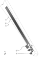
- FIG. 1 to 4 an embodiment of a switch component according to the invention is shown, here designed as a tongue device 5.
- the tongue device 5 has an upper part 1 and a lower part 2.
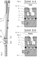
- the sections of the Figures 3 and 4 provide an insight into the vertical division into upper 1 and lower part 2.
- Figure 1 shows in perspective only the lower part with its contact surfaces 3 facing upwards.
- the upper and lower parts are in contact with each other with the contact surfaces 3. From the side, you can see in the sections of the Figures 3 and 4 that the upper part and the lower part are welded together 4.
- an inner cavity 10 is formed, in this case milled, below the tongue 6, approximately following the tongue 6 of the tongue device 5.
- the cavity 10 has two outwardly open connecting openings 12.1, 12.2.
- the connecting openings 12.1, 12.2 conduct heating medium into a supply line 11 and a return line 13 of a heating system.
- a geothermal system or a pipe connected to a solar collector can be considered as a heating system.
- the upper part 1 and the lower part 2 can be connected to one another in a generally form-fitting, material-fitting or force-fitting manner as an alternative to welding.
- the cavity 10 has two spaces formed in the lower part 2 and connected by a connecting line 20 external to the switch.
- upper parts can be designed with cavities that are integrated into a heating system.
- the cavity can also be designed in both parts according to the invention.
- a further part can also be incorporated into the vertical distribution for heating, essentially a heating layer as an intermediate layer, which is not shown anywhere.
- the cavity 10 is in the Figure 1
- the lower part 2 shown is designed as upwardly open recesses extending as a long groove along the switch component in the direction of travel. Alternatively or additionally, cavities can be designed as short grooves transverse to the switch component. According to the invention, the contact surface 3 adjoins the edge or edges of these recesses.
- the cavity 10 is depicted as a semi-tubular channel.
- the cavity 10 is milled into the lower part 2 of the switch component with a semicircular cross-section. This offers manufacturing and flow-related advantages.
- the rounded groove at the bottom prevents edges and dead spaces, particularly in deflection or curved areas. Further machining of the upper part 1 is not necessary.
- the cavity 10 is a type of heating loop that directly carries a heatable fluid medium.
- the welds 4 provide sufficient sealing.
- seals are provided in the contact surface adjacent to the cavity.
- a manufacturing method according to the invention can be understood for the switch component 5 shown in the figures. Parts 1 and 2 are prepared for welding 4. Whether parts 1 and 2 have already been completely finished or not is irrelevant here.
- the cavity 10 is first milled outwards between the contact surface regions 3 with the two connecting openings 12.
Landscapes
- Engineering & Computer Science (AREA)
- Mechanical Engineering (AREA)
- Architecture (AREA)
- Civil Engineering (AREA)
- Structural Engineering (AREA)
- Manufacture Of Switches (AREA)
- Resistance Heating (AREA)
- Mounting, Exchange, And Manufacturing Of Dies (AREA)
- Details Of Garments (AREA)
- General Induction Heating (AREA)
- Measuring Pulse, Heart Rate, Blood Pressure Or Blood Flow (AREA)
- Train Traffic Observation, Control, And Security (AREA)
Description
- Die Erfindung betrifft einen als Führungseinrichtung ausgeführten Weichenbestandteil, beispielsweise eine Zungenvorrichtung, ein Herzstück oder dergleichen, mit einem oberen Teil und einem unteren Teil, wobei der obere Teil und der untere Teil mit zumindest einer Kontaktfläche aneinander anliegen und wobei der obere Teil und der untere Teil miteinander verbunden sind. Ein solcher Weichenbestandteil kann der
DE 101 24 624 A1 entnommen werden, welche eine sogenannte Sandwich-Bauweise beschreibt. DieWO 2013/120487 A1 beschreibt weiter einen Weichenbestandteil gemäß dem Oberbegriff des Anspruchs 1. Ferner betrifft die Erfindung ein Fertigungsverfahren für einen Weichenbestandteil mit Heizeinrichtung. - Weiterer Stand der Technik beschäftigt sich mit Wärmeübertragereinheiten zur Beheizung von Anlagen und Flächen, mit sogenannten Weichenheizungen, beispielsweise die
EP 2 142 704 B1 . Demgemäß sind zur Wärmeübertragung auf ein zu beheizendes Bauteil Minikanäle in flächenhafter Anordnung in dem Bauteil angeordnet sind. Die Lehre derEP 2 142 704 B1 sucht offensichtlich nach einer Lösung für ein direktes Beheizen von Weichenbestandteilen, allerdings von nicht führenden Weichenbestandteilen. Gleitstühle sind als Anwendungsfall genannt. Gleitstühle führen nicht den Zug sondern allenfalls Teile einer Weiche. DieEP 2 142 704 B1 konzentriert sich ferner auf Sonderbauteile, welche in Schwellenfächer einzusetzen sind. Damit ist mithin immer eine indirekte Beheizung führender Teile vorgeschlagen, keine direkte Beheizung. - Aus
WO 2011/141 550 A1 ist eine Oberbauvorrichtung mit einer Zungenvorrichtung bekannt, wobei sich über die gesamte Länge der Zungenvorrichtung ein Block erstreckt, aus dem ein Zungenbett herausgearbeitet ist. Der Block ist mit Stützen verbunden und über die Stützen auf einer Grundplatte aufgeständert. In einem von den Stützen, der Grundplatte und der Unterseite des Blockes gebildeten Innenraum ist eine Heizung wie ein Heizstab vorgesehen. - Unter führenden Teilen oder Führungseinrichtung versteht diese Beschreibung langgestreckte Weichenteile, wie Zungenvorrichtungen oder dergleichen, welche eine Längsrichtung übereinstimmend mit der Fahrtrichtung des Zuges haben. Es geht der Erfindung auch um ein Beheizen eines in dieser Fahrtrichtung gesehen erheblichen Bereichs eines Weichenbestandteils. Folglich muss ein gattungsgemäßer Weichenbestandteil auch ein gewisses Abmaß entlang dieser Fahrtrichtung aufweisen.
- Ein direktes Einbringen von Minikanälen gemäß
EP 2 142 704 B1 , beispielsweise als Bohrungen, in beliebige Bauteile des 10 Weichenbaus, gilt allerdings auch nach derDE 10 2012 108 586 B3 als zu aufwändig. DieEP 2 142 704 B1 selbst weist außerdem auf Verformungen hin, die beim direkten Beheizen auftreten. Wärmeübertragereinheiten gemäßEP 2 142 704 B1 sind an den Auflagepunkten an der Weiche mit verformbaren Elementen 15 gelagert. - Daher wird allgemein weiterhin der Einsatz separat gefertigter Wärmeübertrager mit Kontakt zu Weichenbestandteilen verbessert, vgl.
DE 10 2012 108 686 B3 . Dort wird die Lehre der oben genanntenEP 2 142 704 B1 (auchWO 2008/131732 A1 ) als problematisch gewürdigt. Nachteilig seien die hohen Fertigungskosten einzeln einzubringender Minikanäle. Bohrungen seien zudem nur linear ausführbar, die Gestaltungsfreiheit sei eingeschränkt. - Der vorliegenden Erfindung liegt die Aufgabe zugrunde, ein kostengünstig zu fertigendes Fertigungsverfahren zu entwickeln, dass eine möglichst direkte Beheizbarkeit führender Weichenbestandteile vorsieht.
- Diese Aufgabe wird durch einen Weichenbestandteil aufweisend die kennzeichnenden Merkmale des Anspruchs 1 in Verbindung mit seinen Oberbegriffsmerkmalen gelöst, ferner durch ein Fertigungsverfahren nach Anspruch 10.
- Weitere vorteilhafte Ausgestaltungen der Erfindung bilden die Gegenstände weiterer Ansprüche.
- Erfindungsgemäß ist zumindest ein innerer Hohlraum zwischen dem oberen Teil und dem unteren Teil geformt, welcher Hohlraum zumindest eine nach außen offene Verbindungsöffnung aufweist. Die Erfindung nutzt demnach die horizontal geteilte Bauweise von Weichenbestandteilen mit Führungseigenschaft, unter welcher Bauweise zumindest auch die Sandwich-Bauweise gemäß
DE 10 124 624 fällt, um in der Teilungsfläche, die zur Bearbeitung zur Verfügung steht, zumindest einen Raum für eine Heizeinrichtung schaffen und zu nutzen. Die Erfindung betrifft allgemein horizontal geteilt gebaute Weichenbestandteile, auch solche, die schon durch ihre Bauart Hohlräume aufweisen, die sich in Längsrichtung erstrecken. Der Idee der Erfindung folgend, können auch vorhandene Hohlräume im Inneren der Weichenbestandteile in ein Netz zur Beheizung integriert werden. Das bietet eine Vielfalt an Möglichkeiten für die Fertigung. Das bekannte Limit von beispielsweise Bohrungen ist mithin überwunden. - Ein großer Vorteil, diese horizontale Schnittfläche für das Unterbringen der Heizeinrichtung bzw. eine zumindest grob horizontal vorhandene Schnittfläche zum Erreichen einer Heizfunktion auszubauen, wird weiterhin darin gesehen, dass beim direkten Beheizen zu befürchtende Verformungen besser beherrschbar sind, weil in horizontaler Schichtanordnung in bevorzugten Ausführungsformen unterschiedliche Materialien verwendet und nachträglich als Teile des Weichenbestandteils verbunden werden. Der erfindungsgemäße Weichenbestandteil ist nicht auf eine Aufteilung in zwei vertikal übereinander angeordnete Bestandteilschichten beschränkt. Die Erfindung umfasst ausdrücklich eine als horizontale Schicht eingezogene Platte, die vorteilhaft als Wärmeübertragerplatte eingezogen ist, als unteres oder ein mittleres Teil. Dabei werden als Materialkombinationen, die sich während der Erfindung als vorteilhaft erwiesen haben genannt: Stahl hochfester Güte für die oberen, führenden Teile und Baustahl für den unteren Heizbereich. Die Materialkombination mit Verschweißung lässt ein Steuern oder Begrenzen der Verformung durch Erwärmung zu.
- Bei erfindungsgemäßen Ausführungsformen, insbesondere mit Baustahl und größeren Bauteilvolumina, hielten sich Verformungen in zufrieden stellenden Grenzen.
- Gemäß einer weiteren Ausführungsform eines erfindungsgemäßen Weichenbestandteils sind Außenflächen des Weichenbestandteils zumindest wärmeisoliert. Besonders bevorzugt wird die Wärmeisolierfunktion bei der Auslegung eines Erschütterungsschutzes berücksichtigt.
- Ein erfindungsgemäßes Fertigungsverfahren weist zumindest die Verfahrensschritte auf: ein Bereitstellen eines oberen und eines unteren Teils eines Eisenbahnweichenbestandteils mit einander zuwendbaren und miteinander verbindbaren Kontaktflächen, insbesondere zur Vorbereitung einer Fertigung nach dem Sandwich-Verfahren, ein Versehen des zumindest einen Hohlraums in zumindest einer der Kontaktflächen oder zwischen Kontaktflächenbereichen mit zumindest einer Verbindungöffnung nach außen, die aus dem Bereich der Kontaktflächen herausführt, um den Hohlraum in ein Heizsystem zu integrieren oder um einem Heizsystem mit beispielsweise Zu- und Ablauf einen Zugang in den Weichenbestandteil zu gewähren.
- Gemäß einer Ausführungsform des erfindungsgemäßen Verfahrens werden der Hohlraum und die Verbindungsöffnung in einem einzigen Fertigungsverfahrensschritt, insbesondere spanend, in einer Oberfläche zumindest eines der Teile gefertigt.
Zur Verdeutlichung der Erfindung ist in den nachfolgend beschriebenen Figuren ein Ausführungsbeispiel angegeben. Es zeigen: - Fig. 1
- ein Ausführungsbeispiel eines unteren Teils eines erfindungsgemäßen Weichenbestandteils in perspektivischer Darstellung,
- Fig. 2
- Weichenbestandteile des ersten Ausführungsbeispiels in einer Draufsicht mit eingetragenen Schnitten quer zur Schienenlängsrichtung und gestrichelt eingetragenen Heizkanälen,
- Fig. 3
- den in
Fig. 2 eingetragenen Schnitt A-A mit beweglicher Zunge, deren Bewegbarkeit im Ausführungsbeispiel gegen Vereisen zu sichern ist, und - Fig. 4
- den in
Fig. 2 eingetragenen Schnitt B-B auf Höhe einer Rücklauföffnung der Heizleitung durch den Weichenbestandteil. - In den
Figuren 1 bis 4 ist ein Ausführungsbeispiel eines erfindungsgemäßen Weichenbestandteils gezeigt, hier ausgeführt als eine Zungenvorrichtung 5. Die Zungenvorrichtung 5 hat einen oberen Teil 1 und einem unteren Teil 2. Die Schnitte derFiguren 3 und 4 gewähren einen Einblick in die vertikale Aufteilung in oberen 1 und unteren Teil 2.Figur 1 zeigt perspektivisch ausschließlich den unteren Teil mit seinen Kontaktflächen 3 nach oben ausgerichtet. - Der obere Teil und der untere Teil liegen mit den Kontaktflächen 3 aneinander an. Seitlich erkennt man in den Schnitten der
Figuren 3 und 4 , dass der obere Teil und der untere Teil miteinander verschweißt 4 sind. - Zwischen den Teilen 1, 2 ist vorliegend etwa der Zunge 6 der Zungenvorrichtung 5 folgend unterhalb der Zunge 6 ein innerer Hohlraum 10 geformt, vorliegend eingefräst. Der Hohlraum 10 weist zwei nach außen offene Verbindungsöffnungen 12.1, 12.2 auf. Die Verbindungsöffnungen 12.1, 12.2 führen Heizmedium in einen Vorlauf 11 und einen Rücklauf 13 eines Heizsystems. Als Heizsystem kommt neben herkömmlichen Heizungen ein Erdwärmesystem oder eine an einen Sonnenlichtkollektor angeschlossene Leitung in Betracht.
- Der obere Teil 1 und der untere Teil 2 können erfindungsgemäß alternativ zum Verschweißen allgemein form-, stoff- oder kraftschlüssig miteinander verbunden sein.
- Der Hohlraum 10 hat im dargestellten Ausführungsbeispiel zwei Räume, die in dem unteren Teil 2 geformt und per weichenexterner Verbindungsleitung 20 verbunden sind. Alternativ können erfindungsgemäß obere Teile mit Hohlräumen ausgeführt sein, die in ein Heizsystem eingebunden werden. Der Hohlraum kann erfindungsgemäß auch in beiden Teilen ausgeführt sein. Es kann auch ein weiterer Teil in die vertikale Verteilung zum Beheizen eingebaut werden, quasi eine Heizschicht als Zwischenlage, was nirgends dargestellt ist.
- Der Hohlraum 10 ist in dem in
Figur 1 dargestellten unteren Teil 2 als nach oben offene, sich entlang des Weichenbestandteils in Fahrtrichtung als lange Nut erstreckende Aussparungen ausgeführt. Alternativ oder zusätzlich können Hohlräume als kurze Nut quer zu dem Weichenbestandteil ausgeführt sein. An deren Rand oder deren Rändern schließt sich erfindungsgemäß die Kontaktfläche 3 an.
Der Hohlraum 10 ist halbröhrenförmig in Kanalform dargestellt. Der Hohlraum 10 ist mit einem halbkreisförmigen Querschnitt in den unteren Teil 2 des Weichenbestandteils eingefräst. Das bietet fertigungstechnische und strömungstechnische Vorteile. Besonders in Umlenk- oder Bogenbereichen verhindert die unten runde Nut Kanten und Toträume. Eine weitere Bearbeitung des oberen Teils 1 ist nicht erforderlich. - Der Hohlraum 10 ist erfindungsgemäß eine Art Heizschleife, die unmittelbar selbst ein beheizbares fluides Medium führend ist. Die Schweißungen 4 dichten ausreichend ab. In der Kontaktfläche sind in weiteren nicht dargestellten Ausführungsformen zum Hohlraum benachbart Dichtungen vorgesehen. Ein erfindungsgemäßes Fertigungsverfahren lässt sich für den gezeigten Weichenbestandteil 5 in den Figuren nachvollziehen. Die Teile 1 und 2 werden zum Verschweißen 4 bereitgestellt. Ob die Teile 1 und 2 schon vollständig endbearbeitet sind oder nicht soll hier keine Rolle spielen. Der Hohlraum 10 wird gemäß dem gezeigten Ausführungsbeispiel vorab zwischen den Kontaktflächenbereichen 3 mit den zwei Verbindungöffnungen 12 nach außen gefräst.
-
- 1
- oberer Teil
- 2
- unterer Teil
- 3
- Kontaktfläche
- 4
- Schweißnaht
- 5
- Zungenvorrichtung
- 6
- Zunge
- 10
- Hohlraum
- 11
- Vorlauf
- 12
- Verbindungsöffnung
- 13
- Rücklauf
- 14
- Leitung
- 20
- Verbindungsleitung
Claims (11)
- Weichenbestandteil, ausgeführt als Führungseinrichtung, wie eine Zungenvorrichtung (5), ein Herzstück oder dergleichen, mit zumindest einem oberen Teil (1) und einem unteren Teil (2), wobei der obere Teil und der untere Teil mit zumindest einer Kontaktfläche (3) aneinander anliegen und wobei der obere Teil und der untere Teil miteinander verbunden sind, wobei zumindest ein innerer Hohlraum (10) zwischen dem oberen Teil (1) und dem unteren Teil (2) geformt ist, welcher Hohlraum (10) zumindest eine nach außen offene Verbindungsöffnung (12) aufweist, dadurch gekennzeichnet, dass der Hohlraum (10) nach der Art einer Heizschleife in einem Kontaktbereich zwischen den Teilen (1, 2) verläuft und dass der Hohlraum (10) unmittelbar selbst ein beheizbares fluides Medium führend ist.
- Weichenbestandteil nach Anspruch 1, dadurch gekennzeichnet, dass der zumindest obere Teil (1) und der untere Teil (2) form-, stoff- oder kraftschlüssig miteinander verbunden sind, besonders bevorzugt verschweißt (4).
- Weichenbestandteil nach einem der Ansprüche 1 oder 2, dadurch gekennzeichnet, dass der Hohlraum (10) einräumig oder mehrräumig in dem unteren Teil (2), dem oberen Teil (1) oder in beiden Teilen (1, 2) ausgeführt ist.
- Weichenbestandteil nach einem der vorangehenden Ansprüche, dadurch gekennzeichnet, dass der Hohlraum (10) in dem unteren Teil (2) als nach oben offene, sich besonders bevorzugt entlang des Weichenbestandteils als lange Nut erstreckende Aussparung oder Aussparungen und/oder als kurze Nut oder Nuten quer zu dem Weichenbestandteil ausgeführt ist, an deren Rand oder Rändern die Kontaktfläche (3) anschließt oder die Kontaktflächen (3) anschließen.
- Weichenbestandteil nach einem der vorangehenden Ansprüche, dadurch gekennzeichnet, dass der Hohlraum (10) halbröhrenförmig oder kanalförmig in der dem jeweils anderen Teil (1, 2) zugewandten Kontaktfläche (3) eines der Teile (1, 2) ausgeformt ist.
- Weichenbestandteil nach Anspruch 5, dadurch gekennzeichnet, dass der Hohlraum (10) mit einem halbkreisförmigen Querschnitt in den Teil (1, 2) des Weichenbestandteils (1) eingefräst ist.
- Weichenbestandteil nach einem der vorangehenden Ansprüche, dadurch gekennzeichnet, dass in der Kontaktfläche zum Hohlraum (10) benachbart eine Dichtung in die zu einem Dichtzweck weiterhin ausgesparte Kontaktfläche eingelegt ist und/oder dass die Abdichtung des Hohlraums (10) durch die Art der Verbindung (4) zwischen den Teilen (1, 2) des Weichenbestandteils ausgeführt ist.
- Weiche mit zumindest einem Weichenbestandteil nach einem der vorangehenden Ansprüche.
- Weiche nach Anspruch 8, dadurch gekennzeichnet, dass der Hohlraum (10) oder die Hohlräume zumindest zweier Weichenbestandteile gemäß einem der Ansprüche 1 bis 7 miteinander verbunden sind, insbesondere mittels einer weichenexternen Verbindungsleitung (20).
- Fertigungsverfahren für einen Weichenbestandteil nach einem der Ansprüche 1 bis 7 mit Heizeinrichtung, aufweisend zumindest die Verfahrensschritte:- Bereitstellen zumindest eines zumindest halbfertigen oberen und zumindest eines zumindest halbfertigen unteren Teils (1, 2) des Weichenbestandteils mit zueinander zuwendbaren und miteinander verbindbaren Kontaktflächen (3), insbesondere zur Vorbereitung einer Fertigung nach dem Sandwich-Verfahren,- Fertigen eines Hohlraums (10) in zumindest einer der Kontaktflächen oder zwischen Kontaktflächenbereichen mit zumindest einer Verbindungöffnung (12, 13) nach außen, die aus dem Bereich der Kontaktflächen (3) herausführt, um den Hohlraum (10) in ein Heizsystem zu integrieren oder um einem Heizsystem einen Zugang in den Weichenbestandteil zu gewähren, wobei der Hohlraum zumindest aus der Verbindungsöffnung selbst besteht.
- Fertigungsverfahren nach Anspruch 10, dadurch gekennzeichnet, dass der Hohlraum (10) und die Verbindungsöffnung (12, 13) nicht raumidentisch ausgeführt sind und der Hohlraum (10) und die Verbindungsöffnung (12, 13) in einem einzigen Fertigungsverfahrensschritt, insbesondere spanend, in einer Oberfläche zumindest eines der Teile gefertigt werden.
Priority Applications (14)
| Application Number | Priority Date | Filing Date | Title |
|---|---|---|---|
| HRP20191658TT HRP20191658T4 (hr) | 2014-11-28 | 2014-11-28 | Skretnička komponenta, skretnica i postupak proizvodnje skretničke komponente s uređajem za zagrijavanje |
| PL14195531.0T PL3026176T5 (pl) | 2014-11-28 | 2014-11-28 | Element zwrotnicy, zwrotnica i sposób wytwarzania elementu zwrotnicy z urządzeniem grzewczym |
| HUE14195531 HUE044452T2 (hu) | 2014-11-28 | 2014-11-28 | Váltóalkatrész, váltó és eljárás fûtõberendezéssel ellátott váltóalkatrész gyártására |
| SI201431327T SI3026176T2 (sl) | 2014-11-28 | 2014-11-28 | Sestavni del kretnice, kretnica in postopek izdelave sestavnega dela kretnice z grelno napravo |
| EP14195531.0A EP3026176B2 (de) | 2014-11-28 | 2014-11-28 | Weichenbestandteil, Weiche und Fertigungsverfahren für einen Weichenbestandteil mit Heizeinrichtung |
| PT14195531T PT3026176T (pt) | 2014-11-28 | 2014-11-28 | Componente de agulha, agulha e procedimento de fabrico para um componente de agulha comportando um dispositivo de aquecimento |
| LTEP14195531.0T LT3026176T (lt) | 2014-11-28 | 2014-11-28 | Jungiklio komponentas, jungiklis ir jungiklio komponento su kaitinimo įrenginiu gamybos būdas |
| FIEP14195531.0T FI3026176T4 (fi) | 2014-11-28 | 2014-11-28 | Vaihde-elin, vaihde ja lämmityslaitteella varustetun vaihde-elimen valmistusmenetelmä |
| ES14195531T ES2735351T5 (en) | 2014-11-28 | 2014-11-28 | Points component, points and production method for a points component with a heating device |
| MEP-2019-213A ME03531B (de) | 2014-11-28 | 2014-11-28 | Weichenbestandteil, Weiche und Fertigungsverfahren für einen Weichenbestandteil mit Heizeinrichtung |
| DK14195531.0T DK3026176T4 (da) | 2014-11-28 | 2014-11-28 | Skiftespor-del, skiftespor og fremgangsmåde til fremstilling af en skiftespor-del med opvarmningsindretning |
| SM20190417T SMT201900417T1 (it) | 2014-11-28 | 2014-11-28 | Componente del deviatoio, deviatoio e metodo di fabbricazione per un componente del deviatoio con apparecchio di riscaldamento |
| RS20190916A RS59118B2 (sr) | 2014-11-28 | 2014-11-28 | Element skretnice, skretnica i postupak izrade za element skretnice sa grejnim uređajem |
| CY20191100788T CY1121839T1 (el) | 2014-11-28 | 2019-07-24 | Εξαρτημα μεταγωγεα, μεταγωγεας και κατασκευαστικες διαδικασιες για ενα εξαρτημα μεταγωγεα με συσκευη θερμανσης |
Applications Claiming Priority (1)
| Application Number | Priority Date | Filing Date | Title |
|---|---|---|---|
| EP14195531.0A EP3026176B2 (de) | 2014-11-28 | 2014-11-28 | Weichenbestandteil, Weiche und Fertigungsverfahren für einen Weichenbestandteil mit Heizeinrichtung |
Publications (3)
| Publication Number | Publication Date |
|---|---|
| EP3026176A1 EP3026176A1 (de) | 2016-06-01 |
| EP3026176B1 EP3026176B1 (de) | 2019-06-26 |
| EP3026176B2 true EP3026176B2 (de) | 2025-05-07 |
Family
ID=51987081
Family Applications (1)
| Application Number | Title | Priority Date | Filing Date |
|---|---|---|---|
| EP14195531.0A Active EP3026176B2 (de) | 2014-11-28 | 2014-11-28 | Weichenbestandteil, Weiche und Fertigungsverfahren für einen Weichenbestandteil mit Heizeinrichtung |
Country Status (14)
| Country | Link |
|---|---|
| EP (1) | EP3026176B2 (de) |
| CY (1) | CY1121839T1 (de) |
| DK (1) | DK3026176T4 (de) |
| ES (1) | ES2735351T5 (de) |
| FI (1) | FI3026176T4 (de) |
| HR (1) | HRP20191658T4 (de) |
| HU (1) | HUE044452T2 (de) |
| LT (1) | LT3026176T (de) |
| ME (1) | ME03531B (de) |
| PL (1) | PL3026176T5 (de) |
| PT (1) | PT3026176T (de) |
| RS (1) | RS59118B2 (de) |
| SI (1) | SI3026176T2 (de) |
| SM (1) | SMT201900417T1 (de) |
Citations (7)
| Publication number | Priority date | Publication date | Assignee | Title |
|---|---|---|---|---|
| US4391425A (en) † | 1978-03-20 | 1983-07-05 | Keep Jr Henry | Railroad switch heater |
| US5004190A (en) † | 1987-11-06 | 1991-04-02 | Bylin Heating Systems, Inc. | Rail heating apparatus |
| DE19920858A1 (de) † | 1999-01-15 | 2000-07-27 | Schreck Mieves Gmbh | Oberbau-Zungenvorrichtung |
| DE10124624A1 (de) † | 2001-03-17 | 2002-10-02 | Weichenbau Laeis Gmbh & Co Kg | Zungenvorrichtung und/oder Herzstück für eine Weiche |
| WO2011141550A1 (de) † | 2010-05-12 | 2011-11-17 | Voestalpine Bwg Gmbh & Co. Kg | Oberbauvorrichtung |
| EP2142704B1 (de) † | 2007-04-25 | 2012-02-29 | Wolfgang Feldmann | Wärmeübertragereinheit zur beheizung von anlagen und flächen und weichenheizung |
| DE102012111357A1 (de) † | 2012-11-23 | 2014-05-28 | Schwihag Ag | Gleitstuhl für eine Schienenweiche |
Family Cites Families (4)
| Publication number | Priority date | Publication date | Assignee | Title |
|---|---|---|---|---|
| EP1142704A4 (de) | 1999-08-27 | 2002-04-17 | Toray Industries | Mehrschichtfolie und dampfbeschichtete folie unter verwendung derselben |
| DE102011100511B4 (de) * | 2011-05-04 | 2012-11-15 | Vossloh Laeis Gmbh & Co.Kg | Fertigungsverfahren für eine Zungenvorrichtung sowie Zungenvorrichtung für eine Weiche |
| EP2626465B1 (de) * | 2012-02-13 | 2014-09-03 | Vossloh Laeis GmbH | Schienenauszugsvorrichtung |
| DE102012108586B3 (de) | 2012-09-13 | 2014-02-13 | Pintsch Aben geotherm GmbH | Wärmeübertrager für Schienen und Weichen und Schienenheizeinrichtung |
-
2014
- 2014-11-28 DK DK14195531.0T patent/DK3026176T4/da active
- 2014-11-28 PT PT14195531T patent/PT3026176T/pt unknown
- 2014-11-28 HR HRP20191658TT patent/HRP20191658T4/hr unknown
- 2014-11-28 SM SM20190417T patent/SMT201900417T1/it unknown
- 2014-11-28 SI SI201431327T patent/SI3026176T2/sl unknown
- 2014-11-28 FI FIEP14195531.0T patent/FI3026176T4/fi active
- 2014-11-28 ES ES14195531T patent/ES2735351T5/es active Active
- 2014-11-28 LT LTEP14195531.0T patent/LT3026176T/lt unknown
- 2014-11-28 EP EP14195531.0A patent/EP3026176B2/de active Active
- 2014-11-28 PL PL14195531.0T patent/PL3026176T5/pl unknown
- 2014-11-28 HU HUE14195531 patent/HUE044452T2/hu unknown
- 2014-11-28 ME MEP-2019-213A patent/ME03531B/de unknown
- 2014-11-28 RS RS20190916A patent/RS59118B2/sr unknown
-
2019
- 2019-07-24 CY CY20191100788T patent/CY1121839T1/el unknown
Patent Citations (7)
| Publication number | Priority date | Publication date | Assignee | Title |
|---|---|---|---|---|
| US4391425A (en) † | 1978-03-20 | 1983-07-05 | Keep Jr Henry | Railroad switch heater |
| US5004190A (en) † | 1987-11-06 | 1991-04-02 | Bylin Heating Systems, Inc. | Rail heating apparatus |
| DE19920858A1 (de) † | 1999-01-15 | 2000-07-27 | Schreck Mieves Gmbh | Oberbau-Zungenvorrichtung |
| DE10124624A1 (de) † | 2001-03-17 | 2002-10-02 | Weichenbau Laeis Gmbh & Co Kg | Zungenvorrichtung und/oder Herzstück für eine Weiche |
| EP2142704B1 (de) † | 2007-04-25 | 2012-02-29 | Wolfgang Feldmann | Wärmeübertragereinheit zur beheizung von anlagen und flächen und weichenheizung |
| WO2011141550A1 (de) † | 2010-05-12 | 2011-11-17 | Voestalpine Bwg Gmbh & Co. Kg | Oberbauvorrichtung |
| DE102012111357A1 (de) † | 2012-11-23 | 2014-05-28 | Schwihag Ag | Gleitstuhl für eine Schienenweiche |
Non-Patent Citations (2)
| Title |
|---|
| Einbauanleitung elektrische Weichenheizung fürRillenschienenweichen,2007(besonders relevant:Seite F1) † |
| Elektrische Weichenheizung, Eitra Hilzinger, 08/2000(besonders relevant: Seite 6) † |
Also Published As
| Publication number | Publication date |
|---|---|
| CY1121839T1 (el) | 2020-07-31 |
| LT3026176T (lt) | 2019-08-12 |
| DK3026176T3 (da) | 2019-10-07 |
| ES2735351T5 (en) | 2025-07-21 |
| EP3026176A1 (de) | 2016-06-01 |
| ES2735351T3 (es) | 2019-12-18 |
| FI3026176T4 (fi) | 2025-07-01 |
| SMT201900417T1 (it) | 2019-11-13 |
| RS59118B2 (sr) | 2025-09-30 |
| HRP20191658T4 (hr) | 2025-06-06 |
| ME03531B (de) | 2020-04-20 |
| PL3026176T3 (pl) | 2019-10-31 |
| PT3026176T (pt) | 2019-09-12 |
| RS59118B1 (sr) | 2019-09-30 |
| EP3026176B1 (de) | 2019-06-26 |
| HUE044452T2 (hu) | 2019-10-28 |
| SI3026176T2 (sl) | 2025-09-30 |
| PL3026176T5 (pl) | 2025-06-09 |
| HRP20191658T1 (hr) | 2019-12-13 |
| DK3026176T4 (da) | 2025-06-30 |
| SI3026176T1 (sl) | 2019-10-30 |
Similar Documents
| Publication | Publication Date | Title |
|---|---|---|
| DE102007047314A1 (de) | Presswerkzeug zum Warmumformen oder/und Presshärten von Werkstücken aus Blech | |
| EP3106823B1 (de) | Wärmeübertrager | |
| DE102015115875A1 (de) | Kühlsystem zum Temperieren einer Kraftfahrzeugbatterie sowie Verfahren zum Betrieb einer Batterieanordnung | |
| EP2106891A1 (de) | Heizplatte für Werkstücke | |
| WO2011141550A1 (de) | Oberbauvorrichtung | |
| EP3026176B1 (de) | Weichenbestandteil, Weiche und Fertigungsverfahren für einen Weichenbestandteil mit Heizeinrichtung | |
| DE3425019A1 (de) | Bodenplatte fuer einen aufgestaenderten boden und aus solchen bodenplatten gebildeter boden | |
| DE102007041013A1 (de) | Warmumformwerkzeug | |
| DE102019105980B4 (de) | Umkehrsammler für ein Kühlsystem einer Traktionsbatterie eines elektrisch betriebenen Fahrzeugs und Kühlsystem für eine Traktionsbatterie | |
| DE202007006464U1 (de) | Heizplatte | |
| DE102014006482A1 (de) | Verfahren zur Herstellung einer Heizplatte für eine Reifenpresse | |
| DE202006012225U1 (de) | Wärmespeicheranordnung mit Langzeitspeichereigenschaften | |
| EP2636438B1 (de) | Filterelement zum Einsatz als Kopf- oder Endelement für eine Filterpresse | |
| DE19854173C2 (de) | Metallschaumformkörper | |
| DE3714623A1 (de) | Plattenwaermetauscher | |
| EP2171365B1 (de) | Heizkörper mit teillastfunktion | |
| DE2036926C3 (de) | Heizplattenpresse | |
| EP0994320B1 (de) | Heizkörper, mit mindestens zwei aufeinanderstehenden Flachrohren | |
| DE102021100079A1 (de) | Herstellungsverfahren für einen Wärmeübertrager durch dynamisches Fügen | |
| EP3109561B1 (de) | Heizkörper | |
| DE112007003415B4 (de) | Heizsystembefestigung an Abrollplatten in einer kontinuierlichen Presse | |
| EP3524910A1 (de) | Heizkörper sowie verfahren zu dessen herstellung | |
| DE2142192C3 (de) | Heißwasser-Radiator | |
| EP3064879B1 (de) | Heizkörpervorrichtung mit kreuzdurchströmung | |
| AT504113B1 (de) | Wärmetausch-einrichtung und verfahren zu deren herstellung |
Legal Events
| Date | Code | Title | Description |
|---|---|---|---|
| PUAI | Public reference made under article 153(3) epc to a published international application that has entered the european phase |
Free format text: ORIGINAL CODE: 0009012 |
|
| AK | Designated contracting states |
Kind code of ref document: A1 Designated state(s): AL AT BE BG CH CY CZ DE DK EE ES FI FR GB GR HR HU IE IS IT LI LT LU LV MC MK MT NL NO PL PT RO RS SE SI SK SM TR |
|
| AX | Request for extension of the european patent |
Extension state: BA ME |
|
| STAA | Information on the status of an ep patent application or granted ep patent |
Free format text: STATUS: REQUEST FOR EXAMINATION WAS MADE |
|
| 17P | Request for examination filed |
Effective date: 20161201 |
|
| RBV | Designated contracting states (corrected) |
Designated state(s): AL AT BE BG CH CY CZ DE DK EE ES FI FR GB GR HR HU IE IS IT LI LT LU LV MC MK MT NL NO PL PT RO RS SE SI SK SM TR |
|
| RAX | Requested extension states of the european patent have changed |
Extension state: BA Payment date: 20161222 Extension state: ME Payment date: 20161222 |
|
| STAA | Information on the status of an ep patent application or granted ep patent |
Free format text: STATUS: EXAMINATION IS IN PROGRESS |
|
| 17Q | First examination report despatched |
Effective date: 20180313 |
|
| GRAP | Despatch of communication of intention to grant a patent |
Free format text: ORIGINAL CODE: EPIDOSNIGR1 |
|
| STAA | Information on the status of an ep patent application or granted ep patent |
Free format text: STATUS: GRANT OF PATENT IS INTENDED |
|
| INTG | Intention to grant announced |
Effective date: 20190327 |
|
| GRAS | Grant fee paid |
Free format text: ORIGINAL CODE: EPIDOSNIGR3 |
|
| GRAA | (expected) grant |
Free format text: ORIGINAL CODE: 0009210 |
|
| STAA | Information on the status of an ep patent application or granted ep patent |
Free format text: STATUS: THE PATENT HAS BEEN GRANTED |
|
| AK | Designated contracting states |
Kind code of ref document: B1 Designated state(s): AL AT BE BG CH CY CZ DE DK EE ES FI FR GB GR HR HU IE IS IT LI LT LU LV MC MK MT NL NO PL PT RO RS SE SI SK SM TR |
|
| AX | Request for extension of the european patent |
Extension state: BA ME |
|
| REG | Reference to a national code |
Ref country code: GB Ref legal event code: FG4D Free format text: NOT ENGLISH |
|
| REG | Reference to a national code |
Ref country code: CH Ref legal event code: EP |
|
| REG | Reference to a national code |
Ref country code: AT Ref legal event code: REF Ref document number: 1148420 Country of ref document: AT Kind code of ref document: T Effective date: 20190715 |
|
| REG | Reference to a national code |
Ref country code: DE Ref legal event code: R096 Ref document number: 502014012054 Country of ref document: DE |
|
| REG | Reference to a national code |
Ref country code: IE Ref legal event code: FG4D Free format text: LANGUAGE OF EP DOCUMENT: GERMAN Ref country code: RO Ref legal event code: EPE |
|
| REG | Reference to a national code |
Ref country code: NL Ref legal event code: FP |
|
| REG | Reference to a national code |
Ref country code: PT Ref legal event code: SC4A Ref document number: 3026176 Country of ref document: PT Date of ref document: 20190912 Kind code of ref document: T Free format text: AVAILABILITY OF NATIONAL TRANSLATION Effective date: 20190826 |
|
| REG | Reference to a national code |
Ref country code: HR Ref legal event code: TUEP Ref document number: P20191658T Country of ref document: HR |
|
| REG | Reference to a national code |
Ref country code: EE Ref legal event code: FG4A Ref document number: E017818 Country of ref document: EE Effective date: 20190722 |
|
| REG | Reference to a national code |
Ref country code: DK Ref legal event code: T3 Effective date: 20191003 |
|
| REG | Reference to a national code |
Ref country code: SE Ref legal event code: TRGR |
|
| REG | Reference to a national code |
Ref country code: GR Ref legal event code: EP Ref document number: 20190402230 Country of ref document: GR Effective date: 20191016 |
|
| REG | Reference to a national code |
Ref country code: HU Ref legal event code: AG4A Ref document number: E044452 Country of ref document: HU |
|
| REG | Reference to a national code |
Ref country code: NO Ref legal event code: T2 Effective date: 20190626 |
|
| REG | Reference to a national code |
Ref country code: HR Ref legal event code: ODRP Ref document number: P20191658T Country of ref document: HR Payment date: 20190913 Year of fee payment: 6 |
|
| REG | Reference to a national code |
Ref country code: SK Ref legal event code: T3 Ref document number: E 32325 Country of ref document: SK |
|
| REG | Reference to a national code |
Ref country code: HR Ref legal event code: T1PR Ref document number: P20191658 Country of ref document: HR |
|
| REG | Reference to a national code |
Ref country code: ES Ref legal event code: FG2A Ref document number: 2735351 Country of ref document: ES Kind code of ref document: T3 Effective date: 20191218 |
|
| REG | Reference to a national code |
Ref country code: DE Ref legal event code: R026 Ref document number: 502014012054 Country of ref document: DE |
|
| PLBI | Opposition filed |
Free format text: ORIGINAL CODE: 0009260 |
|
| REG | Reference to a national code |
Ref country code: FI Ref legal event code: MDE Opponent name: VOESTALPINE VAE GMBH |
|
| 26 | Opposition filed |
Opponent name: VOESTALPINE VAE GMBH Effective date: 20200319 |
|
| PLAX | Notice of opposition and request to file observation + time limit sent |
Free format text: ORIGINAL CODE: EPIDOSNOBS2 |
|
| PG25 | Lapsed in a contracting state [announced via postgrant information from national office to epo] |
Ref country code: BG Free format text: LAPSE BECAUSE OF NON-PAYMENT OF DUE FEES Effective date: 20200531 |
|
| PLBB | Reply of patent proprietor to notice(s) of opposition received |
Free format text: ORIGINAL CODE: EPIDOSNOBS3 |
|
| REG | Reference to a national code |
Ref country code: HR Ref legal event code: ODRP Ref document number: P20191658 Country of ref document: HR Payment date: 20201120 Year of fee payment: 7 |
|
| PLAB | Opposition data, opponent's data or that of the opponent's representative modified |
Free format text: ORIGINAL CODE: 0009299OPPO |
|
| R26 | Opposition filed (corrected) |
Opponent name: VOESTALPINE RAILWAY SYSTEMS GMBH Effective date: 20200319 |
|
| REG | Reference to a national code |
Ref country code: HR Ref legal event code: ODRP Ref document number: P20191658 Country of ref document: HR Payment date: 20211119 Year of fee payment: 8 |
|
| APAH | Appeal reference modified |
Free format text: ORIGINAL CODE: EPIDOSCREFNO |
|
| APBM | Appeal reference recorded |
Free format text: ORIGINAL CODE: EPIDOSNREFNO |
|
| APBP | Date of receipt of notice of appeal recorded |
Free format text: ORIGINAL CODE: EPIDOSNNOA2O |
|
| APBQ | Date of receipt of statement of grounds of appeal recorded |
Free format text: ORIGINAL CODE: EPIDOSNNOA3O |
|
| REG | Reference to a national code |
Ref country code: HR Ref legal event code: ODRP Ref document number: P20191658 Country of ref document: HR Payment date: 20221117 Year of fee payment: 9 |
|
| P01 | Opt-out of the competence of the unified patent court (upc) registered |
Effective date: 20230528 |
|
| REG | Reference to a national code |
Ref country code: HR Ref legal event code: ODRP Ref document number: P20191658 Country of ref document: HR Payment date: 20231121 Year of fee payment: 10 |
|
| APBU | Appeal procedure closed |
Free format text: ORIGINAL CODE: EPIDOSNNOA9O |
|
| REG | Reference to a national code |
Ref country code: HR Ref legal event code: ODRP Ref document number: P20191658 Country of ref document: HR Payment date: 20241120 Year of fee payment: 11 |
|
| PUAH | Patent maintained in amended form |
Free format text: ORIGINAL CODE: 0009272 |
|
| STAA | Information on the status of an ep patent application or granted ep patent |
Free format text: STATUS: PATENT MAINTAINED AS AMENDED |
|
| 27A | Patent maintained in amended form |
Effective date: 20250507 |
|
| AK | Designated contracting states |
Kind code of ref document: B2 Designated state(s): AL AT BE BG CH CY CZ DE DK EE ES FI FR GB GR HR HU IE IS IT LI LT LU LV MC MK MT NL NO PL PT RO RS SE SI SK SM TR |
|
| REG | Reference to a national code |
Ref country code: DE Ref legal event code: R102 Ref document number: 502014012054 Country of ref document: DE |
|
| REG | Reference to a national code |
Ref country code: NL Ref legal event code: FP |
|
| REG | Reference to a national code |
Ref country code: HR Ref legal event code: T4IZ Ref document number: P20191658 Country of ref document: HR |
|
| REG | Reference to a national code |
Ref country code: SK Ref legal event code: T5 Ref document number: E 32325 Country of ref document: SK |
|
| REG | Reference to a national code |
Ref country code: EE Ref legal event code: LD4A Ref document number: E017818 Country of ref document: EE |
|
| REG | Reference to a national code |
Ref country code: SE Ref legal event code: RPEO |
|
| REG | Reference to a national code |
Ref country code: DK Ref legal event code: T4 Effective date: 20250625 |
|
| REG | Reference to a national code |
Ref country code: DE Ref legal event code: R082 Ref document number: 502014012054 Country of ref document: DE Representative=s name: TRIERPATENT BAG MBH, DE |
|
| REG | Reference to a national code |
Ref country code: ES Ref legal event code: DC2A Ref document number: 2735351 Country of ref document: ES Kind code of ref document: T5 Effective date: 20250721 |
|
| REG | Reference to a national code |
Ref country code: GR Ref legal event code: EP Ref document number: 20250401392 Country of ref document: GR Effective date: 20250808 |
|
| PG25 | Lapsed in a contracting state [announced via postgrant information from national office to epo] |
Ref country code: BG Free format text: LAPSE BECAUSE OF NON-PAYMENT OF DUE FEES Effective date: 20200531 |
|
| PGFP | Annual fee paid to national office [announced via postgrant information from national office to epo] |
Ref country code: BG Payment date: 20250725 Year of fee payment: 12 |
|
| PGRI | Patent reinstated in contracting state [announced from national office to epo] |
Ref country code: BG Effective date: 20250729 |
|
| REG | Reference to a national code |
Ref country code: CH Ref legal event code: U11 Free format text: ST27 STATUS EVENT CODE: U-0-0-U10-U11 (AS PROVIDED BY THE NATIONAL OFFICE) Effective date: 20251201 |
|
| PGFP | Annual fee paid to national office [announced via postgrant information from national office to epo] |
Ref country code: PT Payment date: 20251113 Year of fee payment: 12 |
|
| PGFP | Annual fee paid to national office [announced via postgrant information from national office to epo] |
Ref country code: HU Payment date: 20251127 Year of fee payment: 12 |
|
| PGFP | Annual fee paid to national office [announced via postgrant information from national office to epo] |
Ref country code: LU Payment date: 20251118 Year of fee payment: 12 Ref country code: NL Payment date: 20251119 Year of fee payment: 12 |
|
| REG | Reference to a national code |
Ref country code: HR Ref legal event code: ODRP Ref document number: P20191658 Country of ref document: HR Payment date: 20251120 Year of fee payment: 12 |
|
| PGFP | Annual fee paid to national office [announced via postgrant information from national office to epo] |
Ref country code: IS Payment date: 20251119 Year of fee payment: 12 Ref country code: DE Payment date: 20251110 Year of fee payment: 12 |
|
| PGFP | Annual fee paid to national office [announced via postgrant information from national office to epo] |
Ref country code: LT Payment date: 20251114 Year of fee payment: 12 Ref country code: GB Payment date: 20251120 Year of fee payment: 12 |
|
| PGFP | Annual fee paid to national office [announced via postgrant information from national office to epo] |
Ref country code: NO Payment date: 20251120 Year of fee payment: 12 Ref country code: MC Payment date: 20251118 Year of fee payment: 12 |
|
| PGFP | Annual fee paid to national office [announced via postgrant information from national office to epo] |
Ref country code: SM Payment date: 20251114 Year of fee payment: 12 Ref country code: MK Payment date: 20251114 Year of fee payment: 12 Ref country code: AT Payment date: 20251117 Year of fee payment: 12 |
|
| PGFP | Annual fee paid to national office [announced via postgrant information from national office to epo] |
Ref country code: IT Payment date: 20251128 Year of fee payment: 12 Ref country code: FI Payment date: 20251118 Year of fee payment: 12 Ref country code: DK Payment date: 20251119 Year of fee payment: 12 |
|
| PGFP | Annual fee paid to national office [announced via postgrant information from national office to epo] |
Ref country code: HR Payment date: 20251120 Year of fee payment: 12 Ref country code: FR Payment date: 20251120 Year of fee payment: 12 |
|
| PGFP | Annual fee paid to national office [announced via postgrant information from national office to epo] |
Ref country code: TR Payment date: 20251124 Year of fee payment: 12 Ref country code: AL Payment date: 20251114 Year of fee payment: 12 Ref country code: GR Payment date: 20251117 Year of fee payment: 12 Ref country code: BE Payment date: 20251118 Year of fee payment: 12 |
|
| PGFP | Annual fee paid to national office [announced via postgrant information from national office to epo] |
Ref country code: CH Payment date: 20251201 Year of fee payment: 12 Ref country code: SE Payment date: 20251119 Year of fee payment: 12 |
|
| PGFP | Annual fee paid to national office [announced via postgrant information from national office to epo] |
Ref country code: CY Payment date: 20251118 Year of fee payment: 12 Ref country code: IE Payment date: 20251120 Year of fee payment: 12 Ref country code: CZ Payment date: 20251118 Year of fee payment: 12 |
|
| PGFP | Annual fee paid to national office [announced via postgrant information from national office to epo] |
Ref country code: MT Payment date: 20251124 Year of fee payment: 12 Ref country code: LV Payment date: 20251125 Year of fee payment: 12 |
|
| PGFP | Annual fee paid to national office [announced via postgrant information from national office to epo] |
Ref country code: PL Payment date: 20251114 Year of fee payment: 12 |
|
| PGFP | Annual fee paid to national office [announced via postgrant information from national office to epo] |
Ref country code: EE Payment date: 20251118 Year of fee payment: 12 |
|
| PGFP | Annual fee paid to national office [announced via postgrant information from national office to epo] |
Ref country code: SK Payment date: 20251121 Year of fee payment: 12 Ref country code: RO Payment date: 20251124 Year of fee payment: 12 |
|
| PGFP | Annual fee paid to national office [announced via postgrant information from national office to epo] |
Ref country code: RS Payment date: 20251114 Year of fee payment: 12 |
|
| PGFP | Annual fee paid to national office [announced via postgrant information from national office to epo] |
Ref country code: SI Payment date: 20251119 Year of fee payment: 12 Ref country code: ES Payment date: 20251216 Year of fee payment: 12 |