EP3025683B1 - Prothese de pied - Google Patents
Prothese de pied Download PDFInfo
- Publication number
- EP3025683B1 EP3025683B1 EP15191212.8A EP15191212A EP3025683B1 EP 3025683 B1 EP3025683 B1 EP 3025683B1 EP 15191212 A EP15191212 A EP 15191212A EP 3025683 B1 EP3025683 B1 EP 3025683B1
- Authority
- EP
- European Patent Office
- Prior art keywords
- prosthesis according
- foot prosthesis
- loop
- foot
- pin
- Prior art date
- Legal status (The legal status is an assumption and is not a legal conclusion. Google has not performed a legal analysis and makes no representation as to the accuracy of the status listed.)
- Active
Links
- 238000013016 damping Methods 0.000 claims description 57
- 238000005096 rolling process Methods 0.000 claims description 8
- 229920000049 Carbon (fiber) Polymers 0.000 claims description 6
- 239000004917 carbon fiber Substances 0.000 claims description 6
- VNWKTOKETHGBQD-UHFFFAOYSA-N methane Chemical compound C VNWKTOKETHGBQD-UHFFFAOYSA-N 0.000 claims description 6
- 239000002131 composite material Substances 0.000 claims description 5
- 239000000835 fiber Substances 0.000 claims description 5
- 238000006073 displacement reaction Methods 0.000 claims description 4
- 229910000831 Steel Inorganic materials 0.000 claims description 2
- 239000010959 steel Substances 0.000 claims description 2
- 210000002683 foot Anatomy 0.000 description 23
- 238000003780 insertion Methods 0.000 description 4
- 230000037431 insertion Effects 0.000 description 4
- 230000003014 reinforcing effect Effects 0.000 description 4
- 238000004519 manufacturing process Methods 0.000 description 3
- 238000010586 diagram Methods 0.000 description 2
- 210000004744 fore-foot Anatomy 0.000 description 2
- 239000000463 material Substances 0.000 description 2
- 238000000034 method Methods 0.000 description 2
- 230000000750 progressive effect Effects 0.000 description 2
- 230000007704 transition Effects 0.000 description 2
- LNUFLCYMSVYYNW-ZPJMAFJPSA-N [(2r,3r,4s,5r,6r)-2-[(2r,3r,4s,5r,6r)-6-[(2r,3r,4s,5r,6r)-6-[(2r,3r,4s,5r,6r)-6-[[(3s,5s,8r,9s,10s,13r,14s,17r)-10,13-dimethyl-17-[(2r)-6-methylheptan-2-yl]-2,3,4,5,6,7,8,9,11,12,14,15,16,17-tetradecahydro-1h-cyclopenta[a]phenanthren-3-yl]oxy]-4,5-disulfo Chemical compound O([C@@H]1[C@@H](COS(O)(=O)=O)O[C@@H]([C@@H]([C@H]1OS(O)(=O)=O)OS(O)(=O)=O)O[C@@H]1[C@@H](COS(O)(=O)=O)O[C@@H]([C@@H]([C@H]1OS(O)(=O)=O)OS(O)(=O)=O)O[C@@H]1[C@@H](COS(O)(=O)=O)O[C@H]([C@@H]([C@H]1OS(O)(=O)=O)OS(O)(=O)=O)O[C@@H]1C[C@@H]2CC[C@H]3[C@@H]4CC[C@@H]([C@]4(CC[C@@H]3[C@@]2(C)CC1)C)[C@H](C)CCCC(C)C)[C@H]1O[C@H](COS(O)(=O)=O)[C@@H](OS(O)(=O)=O)[C@H](OS(O)(=O)=O)[C@H]1OS(O)(=O)=O LNUFLCYMSVYYNW-ZPJMAFJPSA-N 0.000 description 1
- 238000005299 abrasion Methods 0.000 description 1
- 239000000853 adhesive Substances 0.000 description 1
- 238000004026 adhesive bonding Methods 0.000 description 1
- 230000001070 adhesive effect Effects 0.000 description 1
- 238000005266 casting Methods 0.000 description 1
- 230000008878 coupling Effects 0.000 description 1
- 238000010168 coupling process Methods 0.000 description 1
- 238000005859 coupling reaction Methods 0.000 description 1
- 229920001971 elastomer Polymers 0.000 description 1
- 239000000806 elastomer Substances 0.000 description 1
- 239000011159 matrix material Substances 0.000 description 1
- 239000002184 metal Substances 0.000 description 1
- 230000000149 penetrating effect Effects 0.000 description 1
- 238000004382 potting Methods 0.000 description 1
- 238000004080 punching Methods 0.000 description 1
- 239000011347 resin Substances 0.000 description 1
- 229920005989 resin Polymers 0.000 description 1
Images


Classifications
-
- A—HUMAN NECESSITIES
- A61—MEDICAL OR VETERINARY SCIENCE; HYGIENE
- A61F—FILTERS IMPLANTABLE INTO BLOOD VESSELS; PROSTHESES; DEVICES PROVIDING PATENCY TO, OR PREVENTING COLLAPSING OF, TUBULAR STRUCTURES OF THE BODY, e.g. STENTS; ORTHOPAEDIC, NURSING OR CONTRACEPTIVE DEVICES; FOMENTATION; TREATMENT OR PROTECTION OF EYES OR EARS; BANDAGES, DRESSINGS OR ABSORBENT PADS; FIRST-AID KITS
- A61F2/00—Filters implantable into blood vessels; Prostheses, i.e. artificial substitutes or replacements for parts of the body; Appliances for connecting them with the body; Devices providing patency to, or preventing collapsing of, tubular structures of the body, e.g. stents
- A61F2/50—Prostheses not implantable in the body
- A61F2/60—Artificial legs or feet or parts thereof
- A61F2/66—Feet; Ankle joints
-
- A—HUMAN NECESSITIES
- A61—MEDICAL OR VETERINARY SCIENCE; HYGIENE
- A61F—FILTERS IMPLANTABLE INTO BLOOD VESSELS; PROSTHESES; DEVICES PROVIDING PATENCY TO, OR PREVENTING COLLAPSING OF, TUBULAR STRUCTURES OF THE BODY, e.g. STENTS; ORTHOPAEDIC, NURSING OR CONTRACEPTIVE DEVICES; FOMENTATION; TREATMENT OR PROTECTION OF EYES OR EARS; BANDAGES, DRESSINGS OR ABSORBENT PADS; FIRST-AID KITS
- A61F2/00—Filters implantable into blood vessels; Prostheses, i.e. artificial substitutes or replacements for parts of the body; Appliances for connecting them with the body; Devices providing patency to, or preventing collapsing of, tubular structures of the body, e.g. stents
- A61F2/50—Prostheses not implantable in the body
- A61F2002/5007—Prostheses not implantable in the body having elastic means different from springs, e.g. including an elastomeric insert
-
- A—HUMAN NECESSITIES
- A61—MEDICAL OR VETERINARY SCIENCE; HYGIENE
- A61F—FILTERS IMPLANTABLE INTO BLOOD VESSELS; PROSTHESES; DEVICES PROVIDING PATENCY TO, OR PREVENTING COLLAPSING OF, TUBULAR STRUCTURES OF THE BODY, e.g. STENTS; ORTHOPAEDIC, NURSING OR CONTRACEPTIVE DEVICES; FOMENTATION; TREATMENT OR PROTECTION OF EYES OR EARS; BANDAGES, DRESSINGS OR ABSORBENT PADS; FIRST-AID KITS
- A61F2/00—Filters implantable into blood vessels; Prostheses, i.e. artificial substitutes or replacements for parts of the body; Appliances for connecting them with the body; Devices providing patency to, or preventing collapsing of, tubular structures of the body, e.g. stents
- A61F2/50—Prostheses not implantable in the body
- A61F2002/5016—Prostheses not implantable in the body adjustable
- A61F2002/503—Prostheses not implantable in the body adjustable for adjusting elasticity, flexibility, spring rate or mechanical tension
-
- A—HUMAN NECESSITIES
- A61—MEDICAL OR VETERINARY SCIENCE; HYGIENE
- A61F—FILTERS IMPLANTABLE INTO BLOOD VESSELS; PROSTHESES; DEVICES PROVIDING PATENCY TO, OR PREVENTING COLLAPSING OF, TUBULAR STRUCTURES OF THE BODY, e.g. STENTS; ORTHOPAEDIC, NURSING OR CONTRACEPTIVE DEVICES; FOMENTATION; TREATMENT OR PROTECTION OF EYES OR EARS; BANDAGES, DRESSINGS OR ABSORBENT PADS; FIRST-AID KITS
- A61F2/00—Filters implantable into blood vessels; Prostheses, i.e. artificial substitutes or replacements for parts of the body; Appliances for connecting them with the body; Devices providing patency to, or preventing collapsing of, tubular structures of the body, e.g. stents
- A61F2/50—Prostheses not implantable in the body
- A61F2002/5016—Prostheses not implantable in the body adjustable
- A61F2002/5033—Prostheses not implantable in the body adjustable for adjusting damping
-
- A—HUMAN NECESSITIES
- A61—MEDICAL OR VETERINARY SCIENCE; HYGIENE
- A61F—FILTERS IMPLANTABLE INTO BLOOD VESSELS; PROSTHESES; DEVICES PROVIDING PATENCY TO, OR PREVENTING COLLAPSING OF, TUBULAR STRUCTURES OF THE BODY, e.g. STENTS; ORTHOPAEDIC, NURSING OR CONTRACEPTIVE DEVICES; FOMENTATION; TREATMENT OR PROTECTION OF EYES OR EARS; BANDAGES, DRESSINGS OR ABSORBENT PADS; FIRST-AID KITS
- A61F2/00—Filters implantable into blood vessels; Prostheses, i.e. artificial substitutes or replacements for parts of the body; Appliances for connecting them with the body; Devices providing patency to, or preventing collapsing of, tubular structures of the body, e.g. stents
- A61F2/50—Prostheses not implantable in the body
- A61F2/60—Artificial legs or feet or parts thereof
- A61F2/66—Feet; Ankle joints
- A61F2002/6614—Feet
- A61F2002/6657—Feet having a plate-like or strip-like spring element, e.g. an energy-storing cantilever spring keel
Definitions
- the invention relates to a prosthetic foot.
- every prosthetic foot is to enable the wearer to appear as comfortable as possible and, thanks to the spring properties of the prosthesis, to act as smoothly as possible and to walk closer to the real foot.
- foot prostheses which have a lower part which touches the floor when running.
- An elastic damping element is arranged on the lower part and is primarily offset in the direction of the heel area.
- a metal plate with a suitable fastening means, for example a pyramid holder, is then provided on this elongated damping element, on which a connecting shaft or the like, with which the entire prosthesis is fastened to the leg stump, can be arranged.
- the damping element provides the elastic mobility of this plate relative to the lower part.
- rope or belt loops are provided in front of and behind the plate-side connecting means, for example the pyramid receptacle, which overlap the plate and run to the lower part, and are either fastened to or under this.
- the holding plate is firmly connected or clamped to the lower part in this way.
- These rope or belt connections are flexible insofar as it is possible for the holding plate to deflect relative to the lower part, both in the rear heel area and in the front area located virtually in the center of the foot.
- rebound and thus relaxation of the damping element via the rope or belt loops is limited so that the pretension remains. This double limitation of movement ultimately results in a limitation of the relative mobility of the lower part and the plate relative to one another.
- the invention is therefore based on the problem of specifying an improved prosthetic foot.
- the prosthetic foot provides, on the one hand, a one-piece component forming the upper part and the lower part, which component is preferably made of a carbon fiber composite material, and is therefore a multilayer laminate component.
- Upper part and lower part are connected to each other via a deflection in the toe region, the deflection in the region between z. B. 135 ° - 180 °.
- the connecting means for example the pyramid holder, is located on the upper part.
- the upper part and lower part are spaced apart from one another, but lie approximately congruently one above the other.
- the elastic damping element for example made of a rubber-like material, which serves as an impact damper as described, thus dampening the relative movement from the upper part to the lower part. So both are coupled to each other via the damping element, they form a spring in the area between the damping element and the tip of the foot, which is bent and curved when running is claimed.
- the damping element is usually connected flat to the upper and / or lower part, mostly glued.
- a pressure-soft and tensile connection means which connects the upper part and the lower part to one another, this connection means being guided directly through the damping element in a recess there.
- the damping means is in the area near the heel, in which, for example, the pyramid receptacle is ultimately also arranged, the connection of the upper part to the lower part is consequently also provided in the area below the pyramid receptacle.
- this connecting means is pressure-soft, which means that it yields under load, so that the damping element can deflect.
- it is also tension-resistant, that is to say that the damping element is limited to spring out via the connecting means. In the unloaded state, the connecting means defines the maximum distance from the upper part to the lower part in this area.
- the connecting means is guided through the damping element and thus virtually through the pivot point, the relative movement from the upper part to the lower part and thus the pivoting around the pivot point is not limited by this connecting means neither in the heel region nor in the foot center region or toe region lying in front of it.
- the spring travel is therefore not limited as long as the springs are not in contact, which occurs when rolling over the tip of the foot at the end of the movement. In the event of spring contact, i.e.
- the damping element is preferably not connected to the upper part, so that, in extreme cases, this can move relative to the damping element when viewed in the longitudinal direction of the foot. Lifting it off is not possible using the tensile fastener.
- the foot prosthesis according to the invention consequently enables a significantly more comfortable walking that is closer to that of the real foot.
- the thrust forces occurring in the anterior-posterior direction are not completely prevented, since there are no cable and belt connections limiting the movement, as described in the introduction, so that there are no jerky and noticeable interruptions in the rolling movement.
- the connecting means itself is preferably a rope or a band, wherein the rope or band can either consist of plastic fibers that are high-strength and abrasion-resistant, or of steel wire.
- the rope or band can form a loop, the ends being fixed in a common holding element which is fastened to the lower part, while the loop is fastened to the upper part via a loop holding element which extends through it.
- a fixed connection of the connecting means is only provided on the lower part, where the holding element is fastened accordingly, while the loop is fixed on the upper part via a corresponding loop holding element.
- This loop holding element is preferably a pin which rests on the upper side of the upper part and which passes through the loop which penetrates the upper part in an opening.
- the pin thus serves as a replacement bearing on which the loop is attached. It is in turn supported on the top of the upper part, so that there is consequently a firm connection from the upper part to the lower part.
- a holding element is arranged on the upper part, via which the pin is secured against axial displacement.
- the pin is consequently fixed in its position via this holding element, which is arranged on the upper side of the upper part, so it cannot move in its longitudinal direction and, in extreme cases, slip out of the loop.
- the holding element is, for example, plate-shaped and can have one or two protruding tabs which engage in the opening on the upper part, and two further tabs between which the pin is accommodated. Due to the plate-like design, the holding element is never too high.
- the holding element is virtually fixed in position in the transverse direction or in the longitudinal direction of the pin fixed to it, via the one or the two projecting tabs which protrude toward the underside and which engage in the opening on the upper part side, through which the loop runs, so it cannot itself in move that direction.
- the pin itself is fixed between two further tabs that protrude from the top of the holding element.
- Such a configuration of the holding element is particularly easy to manufacture if the holding element is a holding plate. This is because the corresponding opening in the holding element, through which the loop extends, and the tabs can be easily formed in a simple punching process.
- the pin can also be inserted into a holding plate arranged on the upper side of the upper part.
- This holding plate can carry the fastening means, for example the pyramid receptacle, for example if the upper part is designed accordingly. Since this holding plate is to be arranged above the damping element in such a prosthesis configuration, the fixing of the pin on the holding plate is appropriate in this case.
- the opening that is penetrated by the loop is preferably designed as a slot that extends along the upper part.
- This slot can, for example, extend into the middle area of the prosthesis, so it has a certain length. In extreme cases, it even allows a certain degree of mobility the loop in the slot or the pin, provided that it lies directly on the surface.
- the design as a slot it is of course also conceivable to design the opening as a simple bore.
- Such a holding element is preferably designed as a sleeve in which the rope or band is glued, poured or clamped, the sleeve engaging through the lower part or the upper part in an opening.
- a radial collar is provided on the sleeve, which rests on the lower part or on the upper part, provided that such a sleeve is also to be fastened there.
- the rope or band is first glued or poured into the sleeve to be fixed on the lower part, or is appropriately clamped there, preferably by pouring or gluing.
- the sleeve is then inserted into the lower part and the rope or band is guided into the opening in the damping element.
- the sleeve is now attached to the lower part, for example also glued or cast.
- the upper part is then pressed firmly against the lower part, so that the damping element is compressed. This makes it possible to move the pen through the z. B. to slide through the slot loop and to position it accordingly on the upper part or the holding plate, whereupon the pressure is released again and the connecting means is mounted.
- the rope end there is inserted into the sleeve and glued or potted in it, after which the pressure is relieved after the potting or adhesive has hardened and the sleeve, for example likewise via a corresponding radial collar, is correspondingly fixed to the upper part.
- the sleeve can of course each extend a bit into the elastomer, which has a corresponding widening in this area.
- a third embodiment with regard to the connection of the rope or band with the upper part and the lower part provides for the rope or band to be laminated directly onto the upper part and the lower part.
- the component forming the lower part or upper part preferably consists of a carbon fiber composite material, which usually consists of several carbon fiber layers laminated one above the other.
- the damping element which of course should have a slot-like opening for this purpose in order to push it between the upper part and lower part.
- an essential element is that the rope or band passes through the damping element in a corresponding recess.
- This recess can be designed as a through hole or as a slot, which is optionally open on one side of the damping element. If the damping element is already glued to the lower part before the rope or band is assembled, the recess is preferably designed as an opening through which the rope or band can be guided. If the rope or band is mounted beforehand, the recess is expediently designed as a slot, so that the damping element can be pushed between the upper part and the lower part and the rope or band runs into the slot.
- At least one reinforcing element influencing its damping behavior can be used on the damping element be attachable.
- an insertion receptacle is provided on the damping element, into which the reinforcing element can be inserted.
- This can be a form-fitting connection, which means that the plug-in receptacle and the reinforcing element are correspondingly geometrically shaped.
- Such a reinforcing element e.g. B. from a different hardness than the damping element having plastic, for example, can be provided only on the heel back of the damping element, or on the opposite side.
- a cover which can be detachably attached to the upper part and which covers the fastening region of the connecting means can be provided, such a cover, of course, only being required if the rope or band is fixed either via the pin or a sleeve fixed on the upper part.
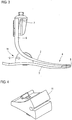
- Figure 1 shows an inventive prosthetic foot 1, consisting of an upper part 2 and a lower part 3, see also the Figures 2 and 3 ,
- the upper part 2 and the lower part 3 are realized by means of a one-piece component 4, the upper part 2 and the lower part 3 being connected to one another in the toe region via a deflection 5.
- the upper part 2 ends in a vertical section 6, on which a fastening means 7 for connecting a prosthesis socket, for example, is arranged via suitable fastening screws 8.
- the component 4 is a one-piece component, preferably made of a carbon fiber composite material. This means that the upper part 2 and the lower part 3 can be formed in a single manufacturing process. As can be seen, the upper part 2 and the lower part 3 are vertically congruent one above the other, ie they run one above the other.
- a longitudinal slot 9 is provided on the upper part 2, which will be discussed below.
- An opening 10 is formed, which will also be discussed below. Slot 9 and opening 10 serve to arrange a connecting element, which is also described below.
- a damping element 11 made of an elastic, rubber-like material is arranged between the upper part 2 and the lower part 3. It is preferably only firmly connected to the lower part 3, for example glued.
- an insertion receptacle 12 is formed, into which an insertion element, which is not shown here, can be used to vary the damping behavior, which is held there in a form-fitting manner.
- a cover 29 is detachably arranged on the upper part 2.
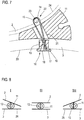
- the Figures 4 - 7 show in detail the damping element 11 and the connecting means 13 penetrating it, via which the upper part 2 and the lower part 3 are connected to one another.
- the damping element has an opening 21, which in the example shown is designed as a simple through hole, see in particular the sectional view in FIG Figure 7 .
- the connecting means 13 comprises a rope 14, preferably a rope made of plastic fibers, but the use of a wire rope is also conceivable.
- the rope 14 is designed as a loop 15. With its two ends, the rope 14 is received in a holding element 16, here in the form of a sleeve 17, and firmly anchored therein by means of a casting compound 18. In the assembly position, the sleeve 17 is inserted into the opening 10 on the lower part and rests on the underside 20 of the lower part 3 via a radial collar 19.
- the cable 14 is guided through the opening 21 of the damping element 11 and emerges towards the upper part 2. It passes through the upper part 2 in the slot 9, that is, it is passed through the slot 9.
- a loop holding element 22, here in the form of a pin 23, is inserted through the loop 15. In the assembly position, the pin 23 is located, see the sectional view according to Figure 7 , on the top 24 of the upper part 2. This fixes the cable 14 to the upper part 2.
- FIG. 8 shows in the form of three basic representations I, II and III the relative movement of the upper part 2 to the lower part 3. It is assumed that the view I shows the heel attachment process, ie when the heel section 24 of the lower part 3 touches the ground. As can be seen, the upper part 2 can pivot in or deflect towards the heel without the connecting means 13, that is to say the cable connection, limiting this movement in any way. In Figure 8 the respective swivel area is shown covered, nevertheless the basic principle can be seen from this.
- Illustration II shows the condition when the prosthesis lies flat with the lower part on the floor.
- Upper part 2 and lower part 3 run, only loaded vertically, one above the other, the transition from the situation according to illustration I to illustration II via the connecting means 13 being in no way impeded.
- Representation III finally shows the rolling process over the toe 25 of the lower part 3.
- the upper part 2 can deflect in the area of the toe to the lower part 3, while a movement apart is possible in the heel area.
- the prosthesis according to the invention thus ensures that the thrust forces occurring in the anterior-posterior direction are not completely prevented, or in any way there is no relative mobility limited by the connecting means, so that there are no jerky interruptions in the rolling movement that are perceptible to the user. Rather, there is a round, homogeneous placement and rolling process.
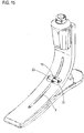
- Figure 9 shows a schematic diagram of the entire foot prosthesis 1, corresponding to the schematic diagrams Figure 8 .
- Figure 10 shows a further embodiment of a prosthetic foot 1 according to the invention, the same reference numerals being used for the same components.
- This also has an upper part 2 and a lower part 3, which consist of a one-piece carbon fiber composite component 4. Here, too, they merge into one another via a deflection 5.
- a damping element 11 is provided between the upper part 2 and lower part 3, the upper part 2 being geometrically different in this embodiment than in the previously described embodiment.
- the upper part 2 runs almost parallel to the lower part 3 towards the heel area.
- a holding plate 26 is arranged on the upper part 2 and carries the fastening element, to which, for example, a connecting shaft is attached.
- a connection means 13 comprising a rope 14, which forms a loop 15.
- the lower rope ends are in turn received in a sleeve 17 which is fastened to the lower part in a manner corresponding to that described in the previous figures.
- the cable 14 in turn runs through an opening 21 in the damping element 11. It is guided through an opening provided in the upper part 2 to a recess 27 in the holding plate 26, in which recess a pin 23 is inserted, on which in turn the loop 15 is suspended.
- the pin 23 is fixed in a corresponding insertion holder on the holding plate 26. Consequently, here the pin 23 is not attached directly to the upper part 2, but to the holding plate 26 fastened on the upper part side.
- Figure 11 shows a further embodiment in which the rope 14 is directly laminated to the upper part 2 and the lower part 3.
- the basic illustration shows the individual rope fibers 28 which are integrated in the upper part 2 and the lower part 3 directly into the laminate or resin matrix. They in turn pass through the damping element 11, which is only retrofitted in this embodiment and which, for example, has a suitable slot for this purpose, which leads into the corresponding opening 21, so that the damping element 11 between the upper part 2 and the lower part 3, the cable 14 in itself receiving, can be pushed.
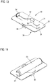
- Figure 12 finally shows an embodiment in which the connecting means 13 has both a sleeve 17 fixed to the lower part 3 and a sleeve 17 fixed to the upper part 2.
- the rope 14 is consequently fixed with its ends in two sleeves 17, it does not form a loop in this embodiment.
- the function is basically the same as described for the above embodiments.
- FIG 13 shows a holding element 30 in the form of a plate-shaped holding plate 31, which the fixing of the in the embodiment according to the Figures 1-7 provided pin serves.
- the holding plate 31 has a central opening 32.
- two further tabs 36 are provided, which are positioned centrally between the tabs 34, but, as said, project to the other side.
- the tabs 36 engage in the slot 9, see the illustration in FIG Figure 15 , By means of this tab engagement, the holding plate 31 itself is secured against lateral displacement, so that it cannot move in this direction.
Claims (19)
- Prothèse de pied comprenant une partie supérieure (2) et une partie inférieure (3) à poser côté sol lors de la marche, lesquelles sont disposées l'une au-dessus de l'autre et de manière espacée l'une de l'autre et sont reliées entre elles à la pointe du pied, cependant que la partie supérieure (2) et la partie inférieure (3) sont constituées au moyen d'une pièce d'un seul tenant (4), et cependant que, dans la zone proche du talon, un élément élastique d'amortissement (11) est agencé entre la partie supérieure (2) et la partie inférieure (3) et est relié à la partie supérieure (2) et/ou à la partie inférieure (3), caractérisée en ce que
un élément de liaison (13) souple à la pression et résistant à la traction est prévu, lequel relie la partie supérieure (2) et la partie inférieure (3) et passe à travers un évidement (21) dans l'élément d'amortissement (11) et à travers un pivot constitué par l'élément d'amortissement (11), pivot autour duquel la partie supérieure (2) peut, relativement à la partie inférieure (3), pivoter lors de la marche pendant que le talon se pose jusqu'au déroulement passant par la pointe du pied. - Prothèse de pied selon la revendication 1, caractérisée en ce que l'élément de liaison (13) est une corde (14) ou un ruban.
- Prothèse de pied selon la revendication 2, caractérisée en ce que la corde (14) ou le ruban est en fibres en matière plastique ou fil d'acier.
- Prothèse de pied selon la revendication 2 ou 3, caractérisée en ce que la corde (14) ou le ruban constitue une boucle (15), cependant que les extrémités sont attachées dans un élément commun de maintien (16) fixé à la partie inférieure (3), tandis que la boucle (15) est accrochée à la partie supérieure (2) par l'intermédiaire d'un élément de maintien de boucle (22) qui la retient en passant à travers elle.
- Prothèse de pied selon la revendication 4, caractérisée en ce que l'élément de maintien de boucle (22) est une goupille (23) qui s'appuie à la face supérieure (24) de la partie supérieure (2), et cependant que la goupille (23) retient en passant à travers elle une boucle (15) retenant la partie supérieure (2) en passant à travers elle dans un transpercement (9).
- Prothèse de pied selon la revendication 4, caractérisée en ce que l'élément de maintien de boucle (22) est une goupille (23) qui est enfichée dans une plaque de maintien (26) agencée à la face supérieure (24) de la partie supérieure (2), et cependant que la goupille (23) retient en passant à travers elle une boucle (15) retenant la partie supérieure (2) en passant à travers elle dans un transpercement.
- Prothèse de pied selon la revendication 6, caractérisée par un élément de maintien (30) agencé à la partie supérieure (2), par l'intermédiaire duquel la goupille (23) est assurée axialement contre un déplacement.
- Prothèse de pied selon la revendication 7, caractérisée en ce que, à l'élément de maintien (30), qui est réalisé sous forme de plaquette, une ou deux languettes (34) venant en saillie et s'engageant dans le transpercement (9) côté partie supérieure, et deux autres languettes (36) entre lesquelles la goupille (23) est logée sont prévues.
- Prothèse de pied selon la revendication 7 ou 8, caractérisée en ce que l'élément de maintien (30) est une tôle de maintien (31).
- Prothèse de pied selon une des revendications de 5 à 9, caractérisée en ce que le transpercement est réalisé sous forme de fente (9) qui s'étend le long de la partie supérieure (2), ou sous forme d'alésage.
- Prothèse de pied selon la revendication 2 ou 3, caractérisée en ce que la corde (2) ou le ruban est attaché(e) à ses deux extrémités respectivement dans un élément de maintien (16), cependant que le un élément de maintien (16) est fixé à la partie inférieure (3) et l'autre élément de maintien (16) est fixé à la partie supérieure (2).
- Prothèse de pied selon une des revendications de 4 à 11, caractérisée en ce qu'un élément de maintien (16) est réalisé sous forme de douille (17) dans laquelle la corde (14) ou le ruban est collé(e), scellé(e) ou coincé(e), cependant que la douille (17) retient en passant à travers elle la partie inférieure (3) ou la partie supérieure (2) en passant à travers elle dans un transpercement (10).
- Prothèse de pied selon la revendication 12, caractérisée en ce que la douille (17) est collée à la partie inférieure (3) ou à la partie supérieure (2).
- Prothèse de pied selon la revendication 2 ou 3, caractérisée en ce que la corde (14) ou le ruban est laminé(e) par au moins une extrémité à la partie inférieure (3) ou à la partie supérieure (2).
- Prothèse de pied selon une des revendications précédentes, caractérisée en ce que l'évidement (21) prévu dans l'élément d'amortissement (11) est un perçage traversant ou une fente éventuellement ouvert(e) d'un côté de l'élément d'amortissement (11).
- Prothèse de pied selon une des revendications précédentes, caractérisée en ce que, à l'élément d'amortissement (11), au moins un élément de raidissement influençant son comportement d'amortissement peut être monté.
- Prothèse de pied selon la revendication 16, caractérisée en ce que, à l'élément d'amortissement (11), un logement d'enfichage (12) est prévu, dans lequel l'élément de raidissement peut être enfiché.
- Prothèse de pied selon une des revendications précédentes, caractérisée en ce qu'un recouvrement (29) pouvant être placé de manière détachable sur la partie supérieure (2) et recouvrant la zone de fixation de l'élément de liaison (13) est prévu.
- Prothèse de pied selon une des revendications précédentes, caractérisée en ce que la pièce d'un seul tenant (4) est en un matériau composite à fibres de carbone.
Applications Claiming Priority (1)
| Application Number | Priority Date | Filing Date | Title |
|---|---|---|---|
| DE102014117210.8A DE102014117210B3 (de) | 2014-11-25 | 2014-11-25 | Fußprothese |
Publications (2)
| Publication Number | Publication Date |
|---|---|
| EP3025683A1 EP3025683A1 (fr) | 2016-06-01 |
| EP3025683B1 true EP3025683B1 (fr) | 2019-12-25 |
Family
ID=54360136
Family Applications (1)
| Application Number | Title | Priority Date | Filing Date |
|---|---|---|---|
| EP15191212.8A Active EP3025683B1 (fr) | 2014-11-25 | 2015-10-23 | Prothese de pied |
Country Status (3)
| Country | Link |
|---|---|
| US (1) | US9844450B2 (fr) |
| EP (1) | EP3025683B1 (fr) |
| DE (1) | DE102014117210B3 (fr) |
Families Citing this family (6)
| Publication number | Priority date | Publication date | Assignee | Title |
|---|---|---|---|---|
| US10842653B2 (en) | 2007-09-19 | 2020-11-24 | Ability Dynamics, Llc | Vacuum system for a prosthetic foot |
| ITVR20120251A1 (it) * | 2012-12-27 | 2014-06-28 | Pedro Hornos | Piede artificiale |
| US10874528B2 (en) | 2017-03-09 | 2020-12-29 | Matthew J. Habecker | Foot prosthesis with dynamic variable keel resistance |
| US20200179138A1 (en) | 2018-12-06 | 2020-06-11 | Otto Bock Healthcare Lp | Prosthetic foot with reinforced spring connection |
| CN111494070B (zh) * | 2020-04-22 | 2021-08-10 | 吉林大学 | 一种具有人体横向足弓特征的变刚度假肢脚板 |
| US20230285168A1 (en) * | 2022-03-10 | 2023-09-14 | Össur Iceland Ehf | Mechanical prosthetic foot for multiple activity levels |
Family Cites Families (8)
| Publication number | Priority date | Publication date | Assignee | Title |
|---|---|---|---|---|
| US4959073A (en) * | 1988-06-06 | 1990-09-25 | John Merlette | Foot prosthesis and method of making same |
| US6572659B1 (en) * | 2001-11-01 | 2003-06-03 | Michael W. Ryan | Prosthetic foot |
| AU2003279838A1 (en) * | 2002-10-08 | 2004-05-04 | Applied Composite Technology Inc. | Prosthetic foot with resilient ankle and olbique attachment |
| DE102006004132B4 (de) * | 2006-01-27 | 2019-04-25 | Ottobock Se & Co. Kgaa | Künstlicher Fuß und Verfahren zur Steuerung der Bewegung eines künstlichen Fußes |
| US8317877B2 (en) * | 2008-08-18 | 2012-11-27 | The Ohio Willow Wood Company | Prosthetic foot |
| DE102010034893A1 (de) | 2010-08-19 | 2012-02-23 | Medi Gmbh & Co. Kg | Fußprothese |
| DE102011014994A1 (de) | 2011-03-23 | 2012-09-27 | Otto Bock Healthcare Gmbh | Prothesenfußeinsatz und Prothesenfuß |
| DE102012006023B4 (de) * | 2012-03-27 | 2013-12-24 | Medi Gmbh & Co. Kg | Fußprothese |
-
2014
- 2014-11-25 DE DE102014117210.8A patent/DE102014117210B3/de active Active
-
2015
- 2015-10-23 EP EP15191212.8A patent/EP3025683B1/fr active Active
- 2015-11-19 US US14/945,923 patent/US9844450B2/en active Active
Non-Patent Citations (1)
| Title |
|---|
| None * |
Also Published As
| Publication number | Publication date |
|---|---|
| DE102014117210B3 (de) | 2016-02-11 |
| US9844450B2 (en) | 2017-12-19 |
| EP3025683A1 (fr) | 2016-06-01 |
| US20160143750A1 (en) | 2016-05-26 |
Similar Documents
| Publication | Publication Date | Title |
|---|---|---|
| EP3025683B1 (fr) | Prothese de pied | |
| EP1920128B1 (fr) | Dispositif comprenant une charniere, en particulier une charniere de meuble | |
| DE102011116280B4 (de) | Verbindungssystem und Prothesensystem | |
| EP1748827A1 (fr) | Fixation pour skis de fond ou de telemark | |
| DE202005017160U1 (de) | Befestigungsschiene für einen langgestreckten Gegenstand | |
| DE60112208T2 (de) | Verbesserte Kupplung eines Stiefels an ein Snowboard | |
| DE202006019489U1 (de) | Vorrichtung zur Aufnahme eines Fußes oder eines Schuhs auf einem Sportgerät | |
| DE3142530A1 (de) | "ski-schuh" | |
| EP1846116B1 (fr) | Ski ou appareils similaires permettant de glisser sur la neige, pourvus d'un systeme d'aide au montage de la fixation | |
| DE102011112980B4 (de) | Set aufweisend einen Taucherschuh, einer Taucherflosse sowie einer Kraftübertragungsverbindung zwischen dem Taucherschuh und der Taucherflosse | |
| EP2317038A2 (fr) | Agencement de gâche pour une serrure de véhicule, notamment pour un capot avant | |
| CH660837A5 (de) | Skischuh. | |
| EP3307105B1 (fr) | Chaussure réglable | |
| EP2916678B1 (fr) | Chaussure, notamment chaussure de sport | |
| DE10113107B4 (de) | Ährenheber für Erntemaschinenmähsysteme | |
| EP1680987A1 (fr) | Elément de rembourrage et elément de ressort associé | |
| DE102011086679A1 (de) | Bindung für Gleitbrett mit Stützglied | |
| DE102016201131A1 (de) | Sportschuh mit einer Schale umfassend Hartkunststoff, Verbundwerkstoffe oder eine Kombination davon | |
| DE202006007719U1 (de) | Struktur einer elastischen Stützanordnung für eine Stuhllehne | |
| DE202007013692U1 (de) | Pferdehufschuh | |
| AT514895B1 (de) | Bindungstragplatte zum Verbinden einer Schibindung mit einem Schi sowie damit ausgestatteter Schi | |
| EP3445458B1 (fr) | Chaussure de natation | |
| DE102010043214A1 (de) | Variabler Schuhabsatz und Schuh | |
| DE102010000814B4 (de) | Hufschuh | |
| DE102023107478A1 (de) | Sportschuh mit Gelenksverbindung |
Legal Events
| Date | Code | Title | Description |
|---|---|---|---|
| PUAI | Public reference made under article 153(3) epc to a published international application that has entered the european phase |
Free format text: ORIGINAL CODE: 0009012 |
|
| AK | Designated contracting states |
Kind code of ref document: A1 Designated state(s): AL AT BE BG CH CY CZ DE DK EE ES FI FR GB GR HR HU IE IS IT LI LT LU LV MC MK MT NL NO PL PT RO RS SE SI SK SM TR |
|
| AX | Request for extension of the european patent |
Extension state: BA ME |
|
| STAA | Information on the status of an ep patent application or granted ep patent |
Free format text: STATUS: REQUEST FOR EXAMINATION WAS MADE |
|
| 17P | Request for examination filed |
Effective date: 20161122 |
|
| RBV | Designated contracting states (corrected) |
Designated state(s): AL AT BE BG CH CY CZ DE DK EE ES FI FR GB GR HR HU IE IS IT LI LT LU LV MC MK MT NL NO PL PT RO RS SE SI SK SM TR |
|
| RAP1 | Party data changed (applicant data changed or rights of an application transferred) |
Owner name: OESSUR ICELAND EHF |
|
| RIC1 | Information provided on ipc code assigned before grant |
Ipc: A61F 2/50 20060101ALN20190607BHEP Ipc: A61F 2/66 20060101AFI20190607BHEP |
|
| GRAP | Despatch of communication of intention to grant a patent |
Free format text: ORIGINAL CODE: EPIDOSNIGR1 |
|
| STAA | Information on the status of an ep patent application or granted ep patent |
Free format text: STATUS: GRANT OF PATENT IS INTENDED |
|
| INTG | Intention to grant announced |
Effective date: 20190719 |
|
| GRAS | Grant fee paid |
Free format text: ORIGINAL CODE: EPIDOSNIGR3 |
|
| GRAA | (expected) grant |
Free format text: ORIGINAL CODE: 0009210 |
|
| STAA | Information on the status of an ep patent application or granted ep patent |
Free format text: STATUS: THE PATENT HAS BEEN GRANTED |
|
| AK | Designated contracting states |
Kind code of ref document: B1 Designated state(s): AL AT BE BG CH CY CZ DE DK EE ES FI FR GB GR HR HU IE IS IT LI LT LU LV MC MK MT NL NO PL PT RO RS SE SI SK SM TR |
|
| REG | Reference to a national code |
Ref country code: GB Ref legal event code: FG4D Free format text: NOT ENGLISH |
|
| REG | Reference to a national code |
Ref country code: CH Ref legal event code: EP |
|
| REG | Reference to a national code |
Ref country code: AT Ref legal event code: REF Ref document number: 1216313 Country of ref document: AT Kind code of ref document: T Effective date: 20200115 |
|
| REG | Reference to a national code |
Ref country code: DE Ref legal event code: R096 Ref document number: 502015011308 Country of ref document: DE |
|
| REG | Reference to a national code |
Ref country code: IE Ref legal event code: FG4D Free format text: LANGUAGE OF EP DOCUMENT: GERMAN |
|
| REG | Reference to a national code |
Ref country code: NL Ref legal event code: MP Effective date: 20191225 |
|
| PG25 | Lapsed in a contracting state [announced via postgrant information from national office to epo] |
Ref country code: FI Free format text: LAPSE BECAUSE OF FAILURE TO SUBMIT A TRANSLATION OF THE DESCRIPTION OR TO PAY THE FEE WITHIN THE PRESCRIBED TIME-LIMIT Effective date: 20191225 Ref country code: BG Free format text: LAPSE BECAUSE OF FAILURE TO SUBMIT A TRANSLATION OF THE DESCRIPTION OR TO PAY THE FEE WITHIN THE PRESCRIBED TIME-LIMIT Effective date: 20200325 Ref country code: NO Free format text: LAPSE BECAUSE OF FAILURE TO SUBMIT A TRANSLATION OF THE DESCRIPTION OR TO PAY THE FEE WITHIN THE PRESCRIBED TIME-LIMIT Effective date: 20200325 Ref country code: GR Free format text: LAPSE BECAUSE OF FAILURE TO SUBMIT A TRANSLATION OF THE DESCRIPTION OR TO PAY THE FEE WITHIN THE PRESCRIBED TIME-LIMIT Effective date: 20200326 Ref country code: LV Free format text: LAPSE BECAUSE OF FAILURE TO SUBMIT A TRANSLATION OF THE DESCRIPTION OR TO PAY THE FEE WITHIN THE PRESCRIBED TIME-LIMIT Effective date: 20191225 Ref country code: SE Free format text: LAPSE BECAUSE OF FAILURE TO SUBMIT A TRANSLATION OF THE DESCRIPTION OR TO PAY THE FEE WITHIN THE PRESCRIBED TIME-LIMIT Effective date: 20191225 Ref country code: LT Free format text: LAPSE BECAUSE OF FAILURE TO SUBMIT A TRANSLATION OF THE DESCRIPTION OR TO PAY THE FEE WITHIN THE PRESCRIBED TIME-LIMIT Effective date: 20191225 |
|
| REG | Reference to a national code |
Ref country code: LT Ref legal event code: MG4D |
|
| PG25 | Lapsed in a contracting state [announced via postgrant information from national office to epo] |
Ref country code: HR Free format text: LAPSE BECAUSE OF FAILURE TO SUBMIT A TRANSLATION OF THE DESCRIPTION OR TO PAY THE FEE WITHIN THE PRESCRIBED TIME-LIMIT Effective date: 20191225 Ref country code: RS Free format text: LAPSE BECAUSE OF FAILURE TO SUBMIT A TRANSLATION OF THE DESCRIPTION OR TO PAY THE FEE WITHIN THE PRESCRIBED TIME-LIMIT Effective date: 20191225 |
|
| PG25 | Lapsed in a contracting state [announced via postgrant information from national office to epo] |
Ref country code: AL Free format text: LAPSE BECAUSE OF FAILURE TO SUBMIT A TRANSLATION OF THE DESCRIPTION OR TO PAY THE FEE WITHIN THE PRESCRIBED TIME-LIMIT Effective date: 20191225 |
|
| PG25 | Lapsed in a contracting state [announced via postgrant information from national office to epo] |
Ref country code: NL Free format text: LAPSE BECAUSE OF FAILURE TO SUBMIT A TRANSLATION OF THE DESCRIPTION OR TO PAY THE FEE WITHIN THE PRESCRIBED TIME-LIMIT Effective date: 20191225 Ref country code: PT Free format text: LAPSE BECAUSE OF FAILURE TO SUBMIT A TRANSLATION OF THE DESCRIPTION OR TO PAY THE FEE WITHIN THE PRESCRIBED TIME-LIMIT Effective date: 20200520 Ref country code: EE Free format text: LAPSE BECAUSE OF FAILURE TO SUBMIT A TRANSLATION OF THE DESCRIPTION OR TO PAY THE FEE WITHIN THE PRESCRIBED TIME-LIMIT Effective date: 20191225 Ref country code: RO Free format text: LAPSE BECAUSE OF FAILURE TO SUBMIT A TRANSLATION OF THE DESCRIPTION OR TO PAY THE FEE WITHIN THE PRESCRIBED TIME-LIMIT Effective date: 20191225 Ref country code: CZ Free format text: LAPSE BECAUSE OF FAILURE TO SUBMIT A TRANSLATION OF THE DESCRIPTION OR TO PAY THE FEE WITHIN THE PRESCRIBED TIME-LIMIT Effective date: 20191225 |
|
| PG25 | Lapsed in a contracting state [announced via postgrant information from national office to epo] |
Ref country code: SM Free format text: LAPSE BECAUSE OF FAILURE TO SUBMIT A TRANSLATION OF THE DESCRIPTION OR TO PAY THE FEE WITHIN THE PRESCRIBED TIME-LIMIT Effective date: 20191225 Ref country code: IS Free format text: LAPSE BECAUSE OF FAILURE TO SUBMIT A TRANSLATION OF THE DESCRIPTION OR TO PAY THE FEE WITHIN THE PRESCRIBED TIME-LIMIT Effective date: 20200425 Ref country code: SK Free format text: LAPSE BECAUSE OF FAILURE TO SUBMIT A TRANSLATION OF THE DESCRIPTION OR TO PAY THE FEE WITHIN THE PRESCRIBED TIME-LIMIT Effective date: 20191225 |
|
| REG | Reference to a national code |
Ref country code: DE Ref legal event code: R097 Ref document number: 502015011308 Country of ref document: DE |
|
| PG25 | Lapsed in a contracting state [announced via postgrant information from national office to epo] |
Ref country code: DK Free format text: LAPSE BECAUSE OF FAILURE TO SUBMIT A TRANSLATION OF THE DESCRIPTION OR TO PAY THE FEE WITHIN THE PRESCRIBED TIME-LIMIT Effective date: 20191225 Ref country code: ES Free format text: LAPSE BECAUSE OF FAILURE TO SUBMIT A TRANSLATION OF THE DESCRIPTION OR TO PAY THE FEE WITHIN THE PRESCRIBED TIME-LIMIT Effective date: 20191225 |
|
| PLBE | No opposition filed within time limit |
Free format text: ORIGINAL CODE: 0009261 |
|
| STAA | Information on the status of an ep patent application or granted ep patent |
Free format text: STATUS: NO OPPOSITION FILED WITHIN TIME LIMIT |
|
| PG25 | Lapsed in a contracting state [announced via postgrant information from national office to epo] |
Ref country code: SI Free format text: LAPSE BECAUSE OF FAILURE TO SUBMIT A TRANSLATION OF THE DESCRIPTION OR TO PAY THE FEE WITHIN THE PRESCRIBED TIME-LIMIT Effective date: 20191225 |
|
| 26N | No opposition filed |
Effective date: 20200928 |
|
| PG25 | Lapsed in a contracting state [announced via postgrant information from national office to epo] |
Ref country code: IT Free format text: LAPSE BECAUSE OF FAILURE TO SUBMIT A TRANSLATION OF THE DESCRIPTION OR TO PAY THE FEE WITHIN THE PRESCRIBED TIME-LIMIT Effective date: 20191225 |
|
| PG25 | Lapsed in a contracting state [announced via postgrant information from national office to epo] |
Ref country code: PL Free format text: LAPSE BECAUSE OF FAILURE TO SUBMIT A TRANSLATION OF THE DESCRIPTION OR TO PAY THE FEE WITHIN THE PRESCRIBED TIME-LIMIT Effective date: 20191225 |
|
| REG | Reference to a national code |
Ref country code: DE Ref legal event code: R119 Ref document number: 502015011308 Country of ref document: DE |
|
| REG | Reference to a national code |
Ref country code: CH Ref legal event code: PL |
|
| PG25 | Lapsed in a contracting state [announced via postgrant information from national office to epo] |
Ref country code: MC Free format text: LAPSE BECAUSE OF FAILURE TO SUBMIT A TRANSLATION OF THE DESCRIPTION OR TO PAY THE FEE WITHIN THE PRESCRIBED TIME-LIMIT Effective date: 20191225 Ref country code: LU Free format text: LAPSE BECAUSE OF NON-PAYMENT OF DUE FEES Effective date: 20201023 |
|
| REG | Reference to a national code |
Ref country code: BE Ref legal event code: MM Effective date: 20201031 |
|
| PG25 | Lapsed in a contracting state [announced via postgrant information from national office to epo] |
Ref country code: DE Free format text: LAPSE BECAUSE OF NON-PAYMENT OF DUE FEES Effective date: 20210501 |
|
| PG25 | Lapsed in a contracting state [announced via postgrant information from national office to epo] |
Ref country code: BE Free format text: LAPSE BECAUSE OF NON-PAYMENT OF DUE FEES Effective date: 20201031 Ref country code: CH Free format text: LAPSE BECAUSE OF NON-PAYMENT OF DUE FEES Effective date: 20201031 Ref country code: LI Free format text: LAPSE BECAUSE OF NON-PAYMENT OF DUE FEES Effective date: 20201031 |
|
| PG25 | Lapsed in a contracting state [announced via postgrant information from national office to epo] |
Ref country code: IE Free format text: LAPSE BECAUSE OF NON-PAYMENT OF DUE FEES Effective date: 20201023 |
|
| REG | Reference to a national code |
Ref country code: AT Ref legal event code: MM01 Ref document number: 1216313 Country of ref document: AT Kind code of ref document: T Effective date: 20201023 |
|
| PG25 | Lapsed in a contracting state [announced via postgrant information from national office to epo] |
Ref country code: AT Free format text: LAPSE BECAUSE OF NON-PAYMENT OF DUE FEES Effective date: 20201023 |
|
| PG25 | Lapsed in a contracting state [announced via postgrant information from national office to epo] |
Ref country code: TR Free format text: LAPSE BECAUSE OF FAILURE TO SUBMIT A TRANSLATION OF THE DESCRIPTION OR TO PAY THE FEE WITHIN THE PRESCRIBED TIME-LIMIT Effective date: 20191225 Ref country code: MT Free format text: LAPSE BECAUSE OF FAILURE TO SUBMIT A TRANSLATION OF THE DESCRIPTION OR TO PAY THE FEE WITHIN THE PRESCRIBED TIME-LIMIT Effective date: 20191225 Ref country code: CY Free format text: LAPSE BECAUSE OF FAILURE TO SUBMIT A TRANSLATION OF THE DESCRIPTION OR TO PAY THE FEE WITHIN THE PRESCRIBED TIME-LIMIT Effective date: 20191225 |
|
| PG25 | Lapsed in a contracting state [announced via postgrant information from national office to epo] |
Ref country code: MK Free format text: LAPSE BECAUSE OF FAILURE TO SUBMIT A TRANSLATION OF THE DESCRIPTION OR TO PAY THE FEE WITHIN THE PRESCRIBED TIME-LIMIT Effective date: 20191225 |
|
| P01 | Opt-out of the competence of the unified patent court (upc) registered |
Effective date: 20230518 |
|
| PGFP | Annual fee paid to national office [announced via postgrant information from national office to epo] |
Ref country code: GB Payment date: 20231018 Year of fee payment: 9 |
|
| PGFP | Annual fee paid to national office [announced via postgrant information from national office to epo] |
Ref country code: FR Payment date: 20231016 Year of fee payment: 9 |