EP3025683B1 - Prosthetic foot - Google Patents
Prosthetic foot Download PDFInfo
- Publication number
- EP3025683B1 EP3025683B1 EP15191212.8A EP15191212A EP3025683B1 EP 3025683 B1 EP3025683 B1 EP 3025683B1 EP 15191212 A EP15191212 A EP 15191212A EP 3025683 B1 EP3025683 B1 EP 3025683B1
- Authority
- EP
- European Patent Office
- Prior art keywords
- prosthesis according
- foot prosthesis
- loop
- foot
- pin
- Prior art date
- Legal status (The legal status is an assumption and is not a legal conclusion. Google has not performed a legal analysis and makes no representation as to the accuracy of the status listed.)
- Active
Links
- 238000013016 damping Methods 0.000 claims description 57
- 238000005096 rolling process Methods 0.000 claims description 8
- 229920000049 Carbon (fiber) Polymers 0.000 claims description 6
- 239000004917 carbon fiber Substances 0.000 claims description 6
- VNWKTOKETHGBQD-UHFFFAOYSA-N methane Chemical compound C VNWKTOKETHGBQD-UHFFFAOYSA-N 0.000 claims description 6
- 239000002131 composite material Substances 0.000 claims description 5
- 239000000835 fiber Substances 0.000 claims description 5
- 238000006073 displacement reaction Methods 0.000 claims description 4
- 229910000831 Steel Inorganic materials 0.000 claims description 2
- 239000010959 steel Substances 0.000 claims description 2
- 210000002683 foot Anatomy 0.000 description 23
- 238000003780 insertion Methods 0.000 description 4
- 230000037431 insertion Effects 0.000 description 4
- 230000003014 reinforcing effect Effects 0.000 description 4
- 238000004519 manufacturing process Methods 0.000 description 3
- 238000010586 diagram Methods 0.000 description 2
- 210000004744 fore-foot Anatomy 0.000 description 2
- 239000000463 material Substances 0.000 description 2
- 238000000034 method Methods 0.000 description 2
- 230000000750 progressive effect Effects 0.000 description 2
- 230000007704 transition Effects 0.000 description 2
- LNUFLCYMSVYYNW-ZPJMAFJPSA-N [(2r,3r,4s,5r,6r)-2-[(2r,3r,4s,5r,6r)-6-[(2r,3r,4s,5r,6r)-6-[(2r,3r,4s,5r,6r)-6-[[(3s,5s,8r,9s,10s,13r,14s,17r)-10,13-dimethyl-17-[(2r)-6-methylheptan-2-yl]-2,3,4,5,6,7,8,9,11,12,14,15,16,17-tetradecahydro-1h-cyclopenta[a]phenanthren-3-yl]oxy]-4,5-disulfo Chemical compound O([C@@H]1[C@@H](COS(O)(=O)=O)O[C@@H]([C@@H]([C@H]1OS(O)(=O)=O)OS(O)(=O)=O)O[C@@H]1[C@@H](COS(O)(=O)=O)O[C@@H]([C@@H]([C@H]1OS(O)(=O)=O)OS(O)(=O)=O)O[C@@H]1[C@@H](COS(O)(=O)=O)O[C@H]([C@@H]([C@H]1OS(O)(=O)=O)OS(O)(=O)=O)O[C@@H]1C[C@@H]2CC[C@H]3[C@@H]4CC[C@@H]([C@]4(CC[C@@H]3[C@@]2(C)CC1)C)[C@H](C)CCCC(C)C)[C@H]1O[C@H](COS(O)(=O)=O)[C@@H](OS(O)(=O)=O)[C@H](OS(O)(=O)=O)[C@H]1OS(O)(=O)=O LNUFLCYMSVYYNW-ZPJMAFJPSA-N 0.000 description 1
- 238000005299 abrasion Methods 0.000 description 1
- 239000000853 adhesive Substances 0.000 description 1
- 238000004026 adhesive bonding Methods 0.000 description 1
- 230000001070 adhesive effect Effects 0.000 description 1
- 238000005266 casting Methods 0.000 description 1
- 230000008878 coupling Effects 0.000 description 1
- 238000010168 coupling process Methods 0.000 description 1
- 238000005859 coupling reaction Methods 0.000 description 1
- 229920001971 elastomer Polymers 0.000 description 1
- 239000000806 elastomer Substances 0.000 description 1
- 239000011159 matrix material Substances 0.000 description 1
- 239000002184 metal Substances 0.000 description 1
- 230000000149 penetrating effect Effects 0.000 description 1
- 238000004382 potting Methods 0.000 description 1
- 238000004080 punching Methods 0.000 description 1
- 239000011347 resin Substances 0.000 description 1
- 229920005989 resin Polymers 0.000 description 1
Images


Classifications
-
- A—HUMAN NECESSITIES
- A61—MEDICAL OR VETERINARY SCIENCE; HYGIENE
- A61F—FILTERS IMPLANTABLE INTO BLOOD VESSELS; PROSTHESES; DEVICES PROVIDING PATENCY TO, OR PREVENTING COLLAPSING OF, TUBULAR STRUCTURES OF THE BODY, e.g. STENTS; ORTHOPAEDIC, NURSING OR CONTRACEPTIVE DEVICES; FOMENTATION; TREATMENT OR PROTECTION OF EYES OR EARS; BANDAGES, DRESSINGS OR ABSORBENT PADS; FIRST-AID KITS
- A61F2/00—Filters implantable into blood vessels; Prostheses, i.e. artificial substitutes or replacements for parts of the body; Appliances for connecting them with the body; Devices providing patency to, or preventing collapsing of, tubular structures of the body, e.g. stents
- A61F2/50—Prostheses not implantable in the body
- A61F2/60—Artificial legs or feet or parts thereof
- A61F2/66—Feet; Ankle joints
-
- A—HUMAN NECESSITIES
- A61—MEDICAL OR VETERINARY SCIENCE; HYGIENE
- A61F—FILTERS IMPLANTABLE INTO BLOOD VESSELS; PROSTHESES; DEVICES PROVIDING PATENCY TO, OR PREVENTING COLLAPSING OF, TUBULAR STRUCTURES OF THE BODY, e.g. STENTS; ORTHOPAEDIC, NURSING OR CONTRACEPTIVE DEVICES; FOMENTATION; TREATMENT OR PROTECTION OF EYES OR EARS; BANDAGES, DRESSINGS OR ABSORBENT PADS; FIRST-AID KITS
- A61F2/00—Filters implantable into blood vessels; Prostheses, i.e. artificial substitutes or replacements for parts of the body; Appliances for connecting them with the body; Devices providing patency to, or preventing collapsing of, tubular structures of the body, e.g. stents
- A61F2/50—Prostheses not implantable in the body
- A61F2002/5007—Prostheses not implantable in the body having elastic means different from springs, e.g. including an elastomeric insert
-
- A—HUMAN NECESSITIES
- A61—MEDICAL OR VETERINARY SCIENCE; HYGIENE
- A61F—FILTERS IMPLANTABLE INTO BLOOD VESSELS; PROSTHESES; DEVICES PROVIDING PATENCY TO, OR PREVENTING COLLAPSING OF, TUBULAR STRUCTURES OF THE BODY, e.g. STENTS; ORTHOPAEDIC, NURSING OR CONTRACEPTIVE DEVICES; FOMENTATION; TREATMENT OR PROTECTION OF EYES OR EARS; BANDAGES, DRESSINGS OR ABSORBENT PADS; FIRST-AID KITS
- A61F2/00—Filters implantable into blood vessels; Prostheses, i.e. artificial substitutes or replacements for parts of the body; Appliances for connecting them with the body; Devices providing patency to, or preventing collapsing of, tubular structures of the body, e.g. stents
- A61F2/50—Prostheses not implantable in the body
- A61F2002/5016—Prostheses not implantable in the body adjustable
- A61F2002/503—Prostheses not implantable in the body adjustable for adjusting elasticity, flexibility, spring rate or mechanical tension
-
- A—HUMAN NECESSITIES
- A61—MEDICAL OR VETERINARY SCIENCE; HYGIENE
- A61F—FILTERS IMPLANTABLE INTO BLOOD VESSELS; PROSTHESES; DEVICES PROVIDING PATENCY TO, OR PREVENTING COLLAPSING OF, TUBULAR STRUCTURES OF THE BODY, e.g. STENTS; ORTHOPAEDIC, NURSING OR CONTRACEPTIVE DEVICES; FOMENTATION; TREATMENT OR PROTECTION OF EYES OR EARS; BANDAGES, DRESSINGS OR ABSORBENT PADS; FIRST-AID KITS
- A61F2/00—Filters implantable into blood vessels; Prostheses, i.e. artificial substitutes or replacements for parts of the body; Appliances for connecting them with the body; Devices providing patency to, or preventing collapsing of, tubular structures of the body, e.g. stents
- A61F2/50—Prostheses not implantable in the body
- A61F2002/5016—Prostheses not implantable in the body adjustable
- A61F2002/5033—Prostheses not implantable in the body adjustable for adjusting damping
-
- A—HUMAN NECESSITIES
- A61—MEDICAL OR VETERINARY SCIENCE; HYGIENE
- A61F—FILTERS IMPLANTABLE INTO BLOOD VESSELS; PROSTHESES; DEVICES PROVIDING PATENCY TO, OR PREVENTING COLLAPSING OF, TUBULAR STRUCTURES OF THE BODY, e.g. STENTS; ORTHOPAEDIC, NURSING OR CONTRACEPTIVE DEVICES; FOMENTATION; TREATMENT OR PROTECTION OF EYES OR EARS; BANDAGES, DRESSINGS OR ABSORBENT PADS; FIRST-AID KITS
- A61F2/00—Filters implantable into blood vessels; Prostheses, i.e. artificial substitutes or replacements for parts of the body; Appliances for connecting them with the body; Devices providing patency to, or preventing collapsing of, tubular structures of the body, e.g. stents
- A61F2/50—Prostheses not implantable in the body
- A61F2/60—Artificial legs or feet or parts thereof
- A61F2/66—Feet; Ankle joints
- A61F2002/6614—Feet
- A61F2002/6657—Feet having a plate-like or strip-like spring element, e.g. an energy-storing cantilever spring keel
Definitions
- the invention relates to a prosthetic foot.
- every prosthetic foot is to enable the wearer to appear as comfortable as possible and, thanks to the spring properties of the prosthesis, to act as smoothly as possible and to walk closer to the real foot.
- foot prostheses which have a lower part which touches the floor when running.
- An elastic damping element is arranged on the lower part and is primarily offset in the direction of the heel area.
- a metal plate with a suitable fastening means, for example a pyramid holder, is then provided on this elongated damping element, on which a connecting shaft or the like, with which the entire prosthesis is fastened to the leg stump, can be arranged.
- the damping element provides the elastic mobility of this plate relative to the lower part.
- rope or belt loops are provided in front of and behind the plate-side connecting means, for example the pyramid receptacle, which overlap the plate and run to the lower part, and are either fastened to or under this.
- the holding plate is firmly connected or clamped to the lower part in this way.
- These rope or belt connections are flexible insofar as it is possible for the holding plate to deflect relative to the lower part, both in the rear heel area and in the front area located virtually in the center of the foot.
- rebound and thus relaxation of the damping element via the rope or belt loops is limited so that the pretension remains. This double limitation of movement ultimately results in a limitation of the relative mobility of the lower part and the plate relative to one another.
- the invention is therefore based on the problem of specifying an improved prosthetic foot.
- the prosthetic foot provides, on the one hand, a one-piece component forming the upper part and the lower part, which component is preferably made of a carbon fiber composite material, and is therefore a multilayer laminate component.
- Upper part and lower part are connected to each other via a deflection in the toe region, the deflection in the region between z. B. 135 ° - 180 °.
- the connecting means for example the pyramid holder, is located on the upper part.
- the upper part and lower part are spaced apart from one another, but lie approximately congruently one above the other.
- the elastic damping element for example made of a rubber-like material, which serves as an impact damper as described, thus dampening the relative movement from the upper part to the lower part. So both are coupled to each other via the damping element, they form a spring in the area between the damping element and the tip of the foot, which is bent and curved when running is claimed.
- the damping element is usually connected flat to the upper and / or lower part, mostly glued.
- a pressure-soft and tensile connection means which connects the upper part and the lower part to one another, this connection means being guided directly through the damping element in a recess there.
- the damping means is in the area near the heel, in which, for example, the pyramid receptacle is ultimately also arranged, the connection of the upper part to the lower part is consequently also provided in the area below the pyramid receptacle.
- this connecting means is pressure-soft, which means that it yields under load, so that the damping element can deflect.
- it is also tension-resistant, that is to say that the damping element is limited to spring out via the connecting means. In the unloaded state, the connecting means defines the maximum distance from the upper part to the lower part in this area.
- the connecting means is guided through the damping element and thus virtually through the pivot point, the relative movement from the upper part to the lower part and thus the pivoting around the pivot point is not limited by this connecting means neither in the heel region nor in the foot center region or toe region lying in front of it.
- the spring travel is therefore not limited as long as the springs are not in contact, which occurs when rolling over the tip of the foot at the end of the movement. In the event of spring contact, i.e.
- the damping element is preferably not connected to the upper part, so that, in extreme cases, this can move relative to the damping element when viewed in the longitudinal direction of the foot. Lifting it off is not possible using the tensile fastener.
- the foot prosthesis according to the invention consequently enables a significantly more comfortable walking that is closer to that of the real foot.
- the thrust forces occurring in the anterior-posterior direction are not completely prevented, since there are no cable and belt connections limiting the movement, as described in the introduction, so that there are no jerky and noticeable interruptions in the rolling movement.
- the connecting means itself is preferably a rope or a band, wherein the rope or band can either consist of plastic fibers that are high-strength and abrasion-resistant, or of steel wire.
- the rope or band can form a loop, the ends being fixed in a common holding element which is fastened to the lower part, while the loop is fastened to the upper part via a loop holding element which extends through it.
- a fixed connection of the connecting means is only provided on the lower part, where the holding element is fastened accordingly, while the loop is fixed on the upper part via a corresponding loop holding element.
- This loop holding element is preferably a pin which rests on the upper side of the upper part and which passes through the loop which penetrates the upper part in an opening.
- the pin thus serves as a replacement bearing on which the loop is attached. It is in turn supported on the top of the upper part, so that there is consequently a firm connection from the upper part to the lower part.
- a holding element is arranged on the upper part, via which the pin is secured against axial displacement.
- the pin is consequently fixed in its position via this holding element, which is arranged on the upper side of the upper part, so it cannot move in its longitudinal direction and, in extreme cases, slip out of the loop.
- the holding element is, for example, plate-shaped and can have one or two protruding tabs which engage in the opening on the upper part, and two further tabs between which the pin is accommodated. Due to the plate-like design, the holding element is never too high.
- the holding element is virtually fixed in position in the transverse direction or in the longitudinal direction of the pin fixed to it, via the one or the two projecting tabs which protrude toward the underside and which engage in the opening on the upper part side, through which the loop runs, so it cannot itself in move that direction.
- the pin itself is fixed between two further tabs that protrude from the top of the holding element.
- Such a configuration of the holding element is particularly easy to manufacture if the holding element is a holding plate. This is because the corresponding opening in the holding element, through which the loop extends, and the tabs can be easily formed in a simple punching process.
- the pin can also be inserted into a holding plate arranged on the upper side of the upper part.
- This holding plate can carry the fastening means, for example the pyramid receptacle, for example if the upper part is designed accordingly. Since this holding plate is to be arranged above the damping element in such a prosthesis configuration, the fixing of the pin on the holding plate is appropriate in this case.
- the opening that is penetrated by the loop is preferably designed as a slot that extends along the upper part.
- This slot can, for example, extend into the middle area of the prosthesis, so it has a certain length. In extreme cases, it even allows a certain degree of mobility the loop in the slot or the pin, provided that it lies directly on the surface.
- the design as a slot it is of course also conceivable to design the opening as a simple bore.
- Such a holding element is preferably designed as a sleeve in which the rope or band is glued, poured or clamped, the sleeve engaging through the lower part or the upper part in an opening.
- a radial collar is provided on the sleeve, which rests on the lower part or on the upper part, provided that such a sleeve is also to be fastened there.
- the rope or band is first glued or poured into the sleeve to be fixed on the lower part, or is appropriately clamped there, preferably by pouring or gluing.
- the sleeve is then inserted into the lower part and the rope or band is guided into the opening in the damping element.
- the sleeve is now attached to the lower part, for example also glued or cast.
- the upper part is then pressed firmly against the lower part, so that the damping element is compressed. This makes it possible to move the pen through the z. B. to slide through the slot loop and to position it accordingly on the upper part or the holding plate, whereupon the pressure is released again and the connecting means is mounted.
- the rope end there is inserted into the sleeve and glued or potted in it, after which the pressure is relieved after the potting or adhesive has hardened and the sleeve, for example likewise via a corresponding radial collar, is correspondingly fixed to the upper part.
- the sleeve can of course each extend a bit into the elastomer, which has a corresponding widening in this area.
- a third embodiment with regard to the connection of the rope or band with the upper part and the lower part provides for the rope or band to be laminated directly onto the upper part and the lower part.
- the component forming the lower part or upper part preferably consists of a carbon fiber composite material, which usually consists of several carbon fiber layers laminated one above the other.
- the damping element which of course should have a slot-like opening for this purpose in order to push it between the upper part and lower part.
- an essential element is that the rope or band passes through the damping element in a corresponding recess.
- This recess can be designed as a through hole or as a slot, which is optionally open on one side of the damping element. If the damping element is already glued to the lower part before the rope or band is assembled, the recess is preferably designed as an opening through which the rope or band can be guided. If the rope or band is mounted beforehand, the recess is expediently designed as a slot, so that the damping element can be pushed between the upper part and the lower part and the rope or band runs into the slot.
- At least one reinforcing element influencing its damping behavior can be used on the damping element be attachable.
- an insertion receptacle is provided on the damping element, into which the reinforcing element can be inserted.
- This can be a form-fitting connection, which means that the plug-in receptacle and the reinforcing element are correspondingly geometrically shaped.
- Such a reinforcing element e.g. B. from a different hardness than the damping element having plastic, for example, can be provided only on the heel back of the damping element, or on the opposite side.
- a cover which can be detachably attached to the upper part and which covers the fastening region of the connecting means can be provided, such a cover, of course, only being required if the rope or band is fixed either via the pin or a sleeve fixed on the upper part.
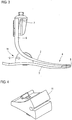
- Figure 1 shows an inventive prosthetic foot 1, consisting of an upper part 2 and a lower part 3, see also the Figures 2 and 3 ,
- the upper part 2 and the lower part 3 are realized by means of a one-piece component 4, the upper part 2 and the lower part 3 being connected to one another in the toe region via a deflection 5.
- the upper part 2 ends in a vertical section 6, on which a fastening means 7 for connecting a prosthesis socket, for example, is arranged via suitable fastening screws 8.
- the component 4 is a one-piece component, preferably made of a carbon fiber composite material. This means that the upper part 2 and the lower part 3 can be formed in a single manufacturing process. As can be seen, the upper part 2 and the lower part 3 are vertically congruent one above the other, ie they run one above the other.
- a longitudinal slot 9 is provided on the upper part 2, which will be discussed below.
- An opening 10 is formed, which will also be discussed below. Slot 9 and opening 10 serve to arrange a connecting element, which is also described below.
- a damping element 11 made of an elastic, rubber-like material is arranged between the upper part 2 and the lower part 3. It is preferably only firmly connected to the lower part 3, for example glued.
- an insertion receptacle 12 is formed, into which an insertion element, which is not shown here, can be used to vary the damping behavior, which is held there in a form-fitting manner.
- a cover 29 is detachably arranged on the upper part 2.
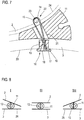
- the Figures 4 - 7 show in detail the damping element 11 and the connecting means 13 penetrating it, via which the upper part 2 and the lower part 3 are connected to one another.
- the damping element has an opening 21, which in the example shown is designed as a simple through hole, see in particular the sectional view in FIG Figure 7 .
- the connecting means 13 comprises a rope 14, preferably a rope made of plastic fibers, but the use of a wire rope is also conceivable.
- the rope 14 is designed as a loop 15. With its two ends, the rope 14 is received in a holding element 16, here in the form of a sleeve 17, and firmly anchored therein by means of a casting compound 18. In the assembly position, the sleeve 17 is inserted into the opening 10 on the lower part and rests on the underside 20 of the lower part 3 via a radial collar 19.
- the cable 14 is guided through the opening 21 of the damping element 11 and emerges towards the upper part 2. It passes through the upper part 2 in the slot 9, that is, it is passed through the slot 9.
- a loop holding element 22, here in the form of a pin 23, is inserted through the loop 15. In the assembly position, the pin 23 is located, see the sectional view according to Figure 7 , on the top 24 of the upper part 2. This fixes the cable 14 to the upper part 2.
- FIG. 8 shows in the form of three basic representations I, II and III the relative movement of the upper part 2 to the lower part 3. It is assumed that the view I shows the heel attachment process, ie when the heel section 24 of the lower part 3 touches the ground. As can be seen, the upper part 2 can pivot in or deflect towards the heel without the connecting means 13, that is to say the cable connection, limiting this movement in any way. In Figure 8 the respective swivel area is shown covered, nevertheless the basic principle can be seen from this.
- Illustration II shows the condition when the prosthesis lies flat with the lower part on the floor.
- Upper part 2 and lower part 3 run, only loaded vertically, one above the other, the transition from the situation according to illustration I to illustration II via the connecting means 13 being in no way impeded.
- Representation III finally shows the rolling process over the toe 25 of the lower part 3.
- the upper part 2 can deflect in the area of the toe to the lower part 3, while a movement apart is possible in the heel area.
- the prosthesis according to the invention thus ensures that the thrust forces occurring in the anterior-posterior direction are not completely prevented, or in any way there is no relative mobility limited by the connecting means, so that there are no jerky interruptions in the rolling movement that are perceptible to the user. Rather, there is a round, homogeneous placement and rolling process.
- Figure 9 shows a schematic diagram of the entire foot prosthesis 1, corresponding to the schematic diagrams Figure 8 .
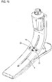
- Figure 10 shows a further embodiment of a prosthetic foot 1 according to the invention, the same reference numerals being used for the same components.
- This also has an upper part 2 and a lower part 3, which consist of a one-piece carbon fiber composite component 4. Here, too, they merge into one another via a deflection 5.
- a damping element 11 is provided between the upper part 2 and lower part 3, the upper part 2 being geometrically different in this embodiment than in the previously described embodiment.
- the upper part 2 runs almost parallel to the lower part 3 towards the heel area.
- a holding plate 26 is arranged on the upper part 2 and carries the fastening element, to which, for example, a connecting shaft is attached.
- a connection means 13 comprising a rope 14, which forms a loop 15.
- the lower rope ends are in turn received in a sleeve 17 which is fastened to the lower part in a manner corresponding to that described in the previous figures.
- the cable 14 in turn runs through an opening 21 in the damping element 11. It is guided through an opening provided in the upper part 2 to a recess 27 in the holding plate 26, in which recess a pin 23 is inserted, on which in turn the loop 15 is suspended.
- the pin 23 is fixed in a corresponding insertion holder on the holding plate 26. Consequently, here the pin 23 is not attached directly to the upper part 2, but to the holding plate 26 fastened on the upper part side.
- Figure 11 shows a further embodiment in which the rope 14 is directly laminated to the upper part 2 and the lower part 3.
- the basic illustration shows the individual rope fibers 28 which are integrated in the upper part 2 and the lower part 3 directly into the laminate or resin matrix. They in turn pass through the damping element 11, which is only retrofitted in this embodiment and which, for example, has a suitable slot for this purpose, which leads into the corresponding opening 21, so that the damping element 11 between the upper part 2 and the lower part 3, the cable 14 in itself receiving, can be pushed.
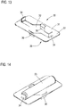
- Figure 12 finally shows an embodiment in which the connecting means 13 has both a sleeve 17 fixed to the lower part 3 and a sleeve 17 fixed to the upper part 2.
- the rope 14 is consequently fixed with its ends in two sleeves 17, it does not form a loop in this embodiment.
- the function is basically the same as described for the above embodiments.
- FIG 13 shows a holding element 30 in the form of a plate-shaped holding plate 31, which the fixing of the in the embodiment according to the Figures 1-7 provided pin serves.
- the holding plate 31 has a central opening 32.
- two further tabs 36 are provided, which are positioned centrally between the tabs 34, but, as said, project to the other side.
- the tabs 36 engage in the slot 9, see the illustration in FIG Figure 15 , By means of this tab engagement, the holding plate 31 itself is secured against lateral displacement, so that it cannot move in this direction.
Landscapes
- Health & Medical Sciences (AREA)
- Transplantation (AREA)
- Biomedical Technology (AREA)
- Cardiology (AREA)
- Oral & Maxillofacial Surgery (AREA)
- Engineering & Computer Science (AREA)
- Orthopedic Medicine & Surgery (AREA)
- Heart & Thoracic Surgery (AREA)
- Vascular Medicine (AREA)
- Life Sciences & Earth Sciences (AREA)
- Animal Behavior & Ethology (AREA)
- General Health & Medical Sciences (AREA)
- Public Health (AREA)
- Veterinary Medicine (AREA)
- Prostheses (AREA)
Description
Die Erfindung betrifft eine Fußprothese.The invention relates to a prosthetic foot.
Fußprothesen sind in unterschiedlicher Ausgestaltung bekannt, zum Beispiel aus der
Ziel jeder Fußprothese ist es dem Träger ein möglichst komfortables und aufgrund der Federeigenschaften der Prothese gedämpftes Auftreten sowie ein dem realen Fuß angenähertes Laufen zu ermöglichen. Bekannt sind unter anderem Fußprothesen, die ein Unterteil aufweisen, das beim Laufen bodenseitig aufsetzt. Am Unterteil angeordnet ist eine elastisches Dämpfungselement, das primär Richtung Fersenbereich versetzt angeordnet ist. Auf diesem länglichen Dämpfungselement ist sodann eine Metallplatte mit einem geeigneten Befestigungsmittel, beispielsweise einer Pyramidenaufnahme vorgesehen, an welcher ein Verbindungsschaft oder dergleichen, mit dem die gesamte Prothese am Beinstumpf befestigt wird, angeordnet werden kann. Das Dämpfungselement stellt die elastische Beweglichkeit dieser Platte relativ zum Unterteil zur Verfügung. Um eine gewisse Vorspannung innerhalb des Dämpfungselements zu erreichen sind vor und hinter dem plattenseitigen Verbindungsmittel, also beispielsweise der Pyramidenaufnahme, Seil- oder Gurtschlaufen vorgesehen, die die Platte übergreifen und zum Unterteil laufen, und entweder an diesem befestigt sind oder dieses untergreifen. Hierüber wird die Halteplatte fest mit dem Unterteil verbunden respektive verspannt. Diese Seil- bzw. Gurtverbindungen sind insoweit flexibel, als ein Einfedern der Halteplatte relativ zum Unterteil möglich ist, und zwar sowohl im hinteren Fersenbereich als auch im vorderen, quasi fußmittig befindlichen Bereich. Jedoch wird ein Ausfedern und damit eine Relaxation des Dämpfungselements über die Seil- oder Gurtschlaufen begrenzt, so dass die Vorspannung bleibt. Aus dieser doppelten Bewegungsbegrenzung resultiert letztlich eine Begrenzung der Relativbeweglichkeit von Unterteil und Platte zueinander. Beim Aufsetzen mit dem Fersenabschnitt ist zwar ein fersenseitiges Einfedern möglich, jedoch kann das vordere Halteplattenende nicht folgen, da es über die dortigen Seil- oder Gurtschlaufe bewegungsbegrenzt ist. Beim Abrollen kann die Halteplatte zwar im vorderen Bereich relativ zum Unterteil einfedern, jedoch ist im Fersenbereich ein Ausfedern nicht möglich, da die Relativbeweglichkeit über die dortige Seil- oder Gurtverbindung begrenzt ist. Das heißt, dass eine Bewegung um den eigentlichen Drehpunkt zwischen dem Rückfuß und dem Vorderfußhebel, also zwischen Halteplatte und Unterteil, nur begrenzt möglich ist, da die Bewegung in beide Richtungen begrenzt ist.The aim of every prosthetic foot is to enable the wearer to appear as comfortable as possible and, thanks to the spring properties of the prosthesis, to act as smoothly as possible and to walk closer to the real foot. Among other things, foot prostheses are known which have a lower part which touches the floor when running. An elastic damping element is arranged on the lower part and is primarily offset in the direction of the heel area. A metal plate with a suitable fastening means, for example a pyramid holder, is then provided on this elongated damping element, on which a connecting shaft or the like, with which the entire prosthesis is fastened to the leg stump, can be arranged. The damping element provides the elastic mobility of this plate relative to the lower part. In order to achieve a certain pretension within the damping element, rope or belt loops are provided in front of and behind the plate-side connecting means, for example the pyramid receptacle, which overlap the plate and run to the lower part, and are either fastened to or under this. The holding plate is firmly connected or clamped to the lower part in this way. These rope or belt connections are flexible insofar as it is possible for the holding plate to deflect relative to the lower part, both in the rear heel area and in the front area located virtually in the center of the foot. However, rebound and thus relaxation of the damping element via the rope or belt loops is limited so that the pretension remains. This double limitation of movement ultimately results in a limitation of the relative mobility of the lower part and the plate relative to one another. When putting on with the heel section, heel-side deflection is possible, but the front end of the holding plate cannot follow because it is limited in movement by the rope or belt loop there. When rolling off, the holding plate can deflect in the front area relative to the lower part, but a rebound is not possible in the heel area, since the relative mobility is via the rope or belt connection there is limited. This means that movement around the actual pivot point between the rear foot and the forefoot lever, i.e. between the holding plate and the lower part, is only possible to a limited extent, since the movement is limited in both directions.
Der Erfindung liegt damit das Problem zugrunde, eine demgegenüber verbesserte Fußprothese anzugeben.The invention is therefore based on the problem of specifying an improved prosthetic foot.
Zur Lösung dieses Problems schlägt die Erfindung eine Fußprothese gemäß Anspruch 1 vor.To solve this problem, the invention proposes a prosthetic foot according to
Erfindungsgemäß sieht die Fußprothese zum einen ein das Oberteil und das Unterteil bildendes einstückiges Bauteil vor, das bevorzugt aus einem Kohlenstofffaserverbundwerkstoff gefertigt ist, mithin also ein mehrlagiges Laminatbauteil ist. Oberteil und Unterteil sind über eine Umlenkung im Fußspitzenbereich miteinander verbunden, wobei die Umlenkung im Bereich zwischen z. B. 135° - 180° geführt ist. Am Oberteil befindet sich das Verbindungsmittel, also beispielsweise die Pyramidenaufnahme. Oberteil und Unterteil sind voneinander beabstandet, liegen jedoch näherungsweise deckungsgleich übereinander. Zwischen ihnen ist im Fersenbereich das elastische Dämpfungselement, beispielsweise aus einem gummiartigen Material, angeordnet, das wie beschrieben als Auftrittsdämpfer dient, mithin also die Relativbewegung von Oberteil zum Unterteil dämpft. Beide sind also über das Dämpfungselement miteinander gekoppelt, sie bilden im Bereich zwischen dem Dämpfungselement und der Fußspitze eine Feder, die beim Laufen gebogen und beansprucht wird. Das Dämpfungselement ist üblicherweise flächig mit dem Ober- und/oder Unterteil verbunden, zumeist verklebt.According to the invention, the prosthetic foot provides, on the one hand, a one-piece component forming the upper part and the lower part, which component is preferably made of a carbon fiber composite material, and is therefore a multilayer laminate component. Upper part and lower part are connected to each other via a deflection in the toe region, the deflection in the region between z. B. 135 ° - 180 °. The connecting means, for example the pyramid holder, is located on the upper part. The upper part and lower part are spaced apart from one another, but lie approximately congruently one above the other. Arranged between them in the heel area is the elastic damping element, for example made of a rubber-like material, which serves as an impact damper as described, thus dampening the relative movement from the upper part to the lower part. So both are coupled to each other via the damping element, they form a spring in the area between the damping element and the tip of the foot, which is bent and curved when running is claimed. The damping element is usually connected flat to the upper and / or lower part, mostly glued.
Erfindungsgemäß ist nun ein druckweiches und zugfestes Verbindungsmittel vorgesehen, das das Oberteil und das Unterteil miteinander verbindet, wobei dieses Verbindungsmittel unmittelbar durch das Dämpfungselement in einer dortigen Ausnehmung geführt ist. Das heißt, dass das Dämpfungsmittel letztlich durch den Drehpunkt, gebildet von dem Dämpfungselement, geführt ist. Da das Dämpfungsmittel im fersennahen Bereich ist, in dem letztlich auch beispielsweise die Pyramidenaufnahme angeordnet ist, ist folglich die Verbindung des Oberteils mit dem Unterteil ebenfalls im Bereich unterhalb der Pyramidenaufnahme vorgesehen. Dieses Verbindungsmittel ist einerseits druckweich, das heißt, dass es bei Belastung nachgibt, so dass das Dämpfungselement einfedern kann. Darüber hinaus ist es aber auch zugfest, das heißt, dass ein Ausfedern des Dämpfungselements über das Verbindungsmittel begrenzt ist. Das Verbindungsmittel definiert im unbelasteten Zustand den maximalen Abstand von Oberteil zu Unterteil in diesen Bereich.According to the invention, a pressure-soft and tensile connection means is now provided which connects the upper part and the lower part to one another, this connection means being guided directly through the damping element in a recess there. This means that the damping means is ultimately guided through the pivot point, formed by the damping element. Since the damping means is in the area near the heel, in which, for example, the pyramid receptacle is ultimately also arranged, the connection of the upper part to the lower part is consequently also provided in the area below the pyramid receptacle. On the one hand, this connecting means is pressure-soft, which means that it yields under load, so that the damping element can deflect. In addition, however, it is also tension-resistant, that is to say that the damping element is limited to spring out via the connecting means. In the unloaded state, the connecting means defines the maximum distance from the upper part to the lower part in this area.
Da erfindungsgemäß das Verbindungsmittel durch das Dämpfungselement und damit quasi durch den Drehpunkt geführt ist, ist über dieses Verbindungsmittel die Relativbewegung von Oberteil zu Unterteil und damit das Verschwenken um den Drehpunkt weder im Fersenbereich noch im davor liegenden Fußmittelbereich respektive Fußspitzenbereich begrenzt. Das heißt, dass das Dämpfungselement und folglich das Oberteil zum Unterteil quasi um den Drehpunkt relativ weit und unbegrenzt einfedern respektive verschwenken können, mithin also eine deutlich verbesserte Relativbewegung von Oberteil zu Unterteil möglich ist. Der Federweg wird folglich nicht begrenzt, solange die Federn nicht in Kontakt stehen, was beim Abrollen über die Fußspitze zum Ende der Bewegung erfolgt. Bei einem Federkontakt, wenn also das Oberteil gegen das Unterteil läuft, wandert der quasi virtuelle Drehpunkt aus dem Dämpfungselement nach vorne in den Kontaktpunkt des Oberteils zum Unterteil, und die Verbindung spannt das Oberteil gegen das Unterteil, was zu einem progressiven Kraftanstieg führt. Es ist somit eine beachtliche Relativbeweglichkeit von Oberteil zum Unterteil in Fußlängsrichtung gegeben, was insbesondere durch die Kopplung über das einzige Verbindungsmittel, das durch das Dämpfungselement läuft, erreicht wird. Zum anderen kann hierzu auch noch beitragen, dass das Dämpfungselement bevorzugt nicht mit dem Oberteil verbunden ist, so dass sich dieses im Extremfall in Fußlängsrichtung gesehen relativ zum Dämpfungselement bewegen kann. Ein Abheben davon ist über das zugfeste Verbindungsmittel ausgeschlossen.Since, according to the invention, the connecting means is guided through the damping element and thus virtually through the pivot point, the relative movement from the upper part to the lower part and thus the pivoting around the pivot point is not limited by this connecting means neither in the heel region nor in the foot center region or toe region lying in front of it. This means that the damping element and consequently the upper part can deflect or pivot relatively far and unlimitedly about the fulcrum relative to the lower part, so that a significantly improved relative movement from the upper part to the lower part is possible. The spring travel is therefore not limited as long as the springs are not in contact, which occurs when rolling over the tip of the foot at the end of the movement. In the event of spring contact, i.e. when the upper part runs against the lower part, the virtually virtual pivot point moves from the damping element forward into the contact point of the upper part to the lower part, and the connection tensions the upper part against the lower part, which leads to a progressive increase in force. It is therefore a remarkable relative mobility from top to bottom in the longitudinal direction of the foot given what is achieved in particular by the coupling via the only connecting means that runs through the damping element. On the other hand, it can also contribute to this that the damping element is preferably not connected to the upper part, so that, in extreme cases, this can move relative to the damping element when viewed in the longitudinal direction of the foot. Lifting it off is not possible using the tensile fastener.
Insgesamt wird mit der erfindungsgemäßen Fußprothese folglich ein wesentlich komfortableres und dem realen Fuß angenähertes Laufen ermöglicht. Die auftretenden Schubkräfte in Anterior-Posterior-Richtung werden nicht vollständig unterbunden, da keine die Bewegung begrenzenden Seil- und Gurtverbindungen, wie einleitend beschrieben, vorgesehen sind, so dass keine ruckartigen und für den Anwender spürbaren Unterbrechungen in der Abrollbewegung entstehen.Overall, the foot prosthesis according to the invention consequently enables a significantly more comfortable walking that is closer to that of the real foot. The thrust forces occurring in the anterior-posterior direction are not completely prevented, since there are no cable and belt connections limiting the movement, as described in the introduction, so that there are no jerky and noticeable interruptions in the rolling movement.
Das Verbindungsmittel selbst ist bevorzugt ein Seil oder ein Band, wobei das Seil oder Band entweder aus Kunststofffasern, die hochfest und abriebfest sind, oder aus Stahldraht bestehen kann.The connecting means itself is preferably a rope or a band, wherein the rope or band can either consist of plastic fibers that are high-strength and abrasion-resistant, or of steel wire.
Hinsichtlich der Ausgestaltung des Verbindungsmittels sowie seiner Befestigung sind unterschiedliche Alternativen denkbar. Gemäß einer ersten Erfindungsalternative kann das Seil oder Band eine Schlaufe bilden, wobei die Enden in einem gemeinsamen Halteelement fixiert sind, das am Unterteil befestigt ist, während die Schlaufe über ein sie durchgreifendes Schlaufenhalteelement am Oberteil befestigt ist. Bei dieser Ausgestaltung ist eine feste Verbindung des Verbindungsmittels nur am Unterteil gegeben, wo das Halteelement entsprechend befestigt ist, während die Schlaufe am Oberteil über ein entsprechendes Schlaufenhalteelement fixiert ist.With regard to the design of the connecting means and its attachment, different alternatives are conceivable. According to a first alternative of the invention, the rope or band can form a loop, the ends being fixed in a common holding element which is fastened to the lower part, while the loop is fastened to the upper part via a loop holding element which extends through it. In this embodiment, a fixed connection of the connecting means is only provided on the lower part, where the holding element is fastened accordingly, while the loop is fixed on the upper part via a corresponding loop holding element.
Dieses Schlaufenhaltelement ist bevorzugt ein Stift, der an der Oberseite des Oberteils aufliegt und der die das Oberteil in einer Durchbrechung durchgreifende Schlaufe durchgreift. Der Stift dient also als Wiederlager, an dem die Schlaufe eingehängt ist. Er ist seinerseits an der Oberseite des Oberteils aufgelagert, so dass folglich eine feste Verbindung von Oberteil zum Unterteil gegeben ist.This loop holding element is preferably a pin which rests on the upper side of the upper part and which passes through the loop which penetrates the upper part in an opening. The pin thus serves as a replacement bearing on which the loop is attached. It is in turn supported on the top of the upper part, so that there is consequently a firm connection from the upper part to the lower part.
Zweckmäßig ist es, wenn am Oberteil ein Halteelement angeordnet ist, über das der Stift gegen ein axiales Verschieben gesichert ist. Über dieses Halteelement, das an der Oberseite des Oberteils angeordnet ist, ist der Stift folglich in seiner Position fixiert, er kann sich also nicht in seiner Längsrichtung bewegen und im Extremfall aus der Schlaufe herausrutschen. Das Halteelement ist beispielsweise plättchenförmig ausgeführt und kann eine oder zwei abstehende Laschen, die in die oberteilseitige Durchbrechung eingreifen, sowie zwei weitere Laschen, zwischen denen der Stift aufgenommen ist, aufweisen. Durch die plättchenartige Ausgestaltung baut das Halteelement in keinem Fall allzu hoch auf. Über die zu seiner Unterseite vorspringende eine oder über die beiden vorspringenden Laschen, die in die oberteilseitige Durchbrechung, durch die die Schlaufe läuft, eingreifen, ist das Halteelement quasi in Querrichtung respektive in Längsrichtung des an ihm fixierten Stiftes positionsfixiert, kann sich also selbst nicht in diese Richtung bewegen. Der Stift selbst ist zwischen zwei weiteren Laschen, die an der Oberseite des Halteelements abstehen, fixiert.It is expedient if a holding element is arranged on the upper part, via which the pin is secured against axial displacement. The pin is consequently fixed in its position via this holding element, which is arranged on the upper side of the upper part, so it cannot move in its longitudinal direction and, in extreme cases, slip out of the loop. The holding element is, for example, plate-shaped and can have one or two protruding tabs which engage in the opening on the upper part, and two further tabs between which the pin is accommodated. Due to the plate-like design, the holding element is never too high. The holding element is virtually fixed in position in the transverse direction or in the longitudinal direction of the pin fixed to it, via the one or the two projecting tabs which protrude toward the underside and which engage in the opening on the upper part side, through which the loop runs, so it cannot itself in move that direction. The pin itself is fixed between two further tabs that protrude from the top of the holding element.
Eine solche Ausgestaltung des Halteelements ist insbesondere dann einfach herstellbar, wenn das Halteelement ein Halteblech ist. Denn die entsprechende Durchbrechung des Halteelements, durch die Schlaufe greift, sowie die Laschen können ohne weiteres in einem einfachen Stanzvorgang ausgeformt werden.Such a configuration of the holding element is particularly easy to manufacture if the holding element is a holding plate. This is because the corresponding opening in the holding element, through which the loop extends, and the tabs can be easily formed in a simple punching process.
Alternativ dazu kann der Stift auch in eine an der Oberseite des Oberteils angeordnete Halteplatte eingesteckt sein. Diese Halteplatte kann beispielsweise bei entsprechender Ausgestaltung des Oberteils das Befestigungsmittel, also beispielsweise die Pyramidenaufnahme tragen. Da diese Halteplatte oberhalb des Dämpfungselements bei einer solchen Prothesenausgestaltung anzuordnen ist, bietet sich in diesem Fall die Fixierung des Stiftes an der Halteplatte an.Alternatively, the pin can also be inserted into a holding plate arranged on the upper side of the upper part. This holding plate can carry the fastening means, for example the pyramid receptacle, for example if the upper part is designed accordingly. Since this holding plate is to be arranged above the damping element in such a prosthesis configuration, the fixing of the pin on the holding plate is appropriate in this case.
Die Durchbrechung, die von der Schlaufe durchgriffen ist, ist bevorzugt als Schlitz, der sich längs des Oberteils erstreckt, ausgeführt. Dieser Schlitz kann sich beispielsweise bis in den mittleren Prothesenbereich erstrecken, erweist also eine gewisse Länge auf. Er ermöglicht im Extremfall sogar eine gewisse Beweglichkeit der Schlaufe in dem Schlitz respektive des Stiftes, sofern dieser auf der Oberfläche direkt aufliegt. Wie beschrieben kommt es beim Abrollen zu einer Berührung von Oberteil und Unterteil und bei einem weiteren Abrollen zu einem hohen Kraftanstieg, verbunden mit einer Relativverschiebung des Oberteils zum Unterteil. Dieser kann die Schlaufe und der Stift wenn nötig letztlich folgen, da sie sich aufgrund der Schlitzausgestaltung geringfügig bewegen können. Alternativ zur Ausführung als Schlitz ist es selbstverständlich auch denkbar, die Durchbrechung als einfache Bohrung auszuführen.The opening that is penetrated by the loop is preferably designed as a slot that extends along the upper part. This slot can, for example, extend into the middle area of the prosthesis, so it has a certain length. In extreme cases, it even allows a certain degree of mobility the loop in the slot or the pin, provided that it lies directly on the surface. As described, there is contact between the upper part and lower part when unrolling and a high increase in force when unrolling, combined with a relative displacement of the upper part to the lower part. This can ultimately follow the loop and the pin if necessary, since they can move slightly due to the slot design. As an alternative to the design as a slot, it is of course also conceivable to design the opening as a simple bore.
Eine Erfindungsalternative zu der beschriebenen Ausgestaltung, bei der das Seil oder Band mittels eines Stiftes fixiert ist, sieht vor, das Seil oder Band mit beiden Enden jeweils in einem Halteelement zu fixieren, wobei das eine Halteelement am Unterteil und das andere Halteelement am Oberteil befestigt ist. Hier läuft also das Seil oder Band geradlinig vom Unterteil zum Oberteil, wo es über die Halteelemente entsprechend befestigt ist.An alternative of the invention to the described embodiment, in which the rope or band is fixed by means of a pin, provides for the rope or band to be fixed with both ends in a holding element, one holding element being fastened to the lower part and the other holding element to the upper part , So here the rope or tape runs in a straight line from the lower part to the upper part, where it is fastened accordingly via the holding elements.
Ein solches Halteelement, unabhängig davon, ob nun eines oder zwei vorgesehen sind, ist bevorzugt als Hülse ausgeführt, in der das Seil oder Band eingeklebt, eingegossen oder eingeklemmt ist, wobei die Hülse das Unterteil oder das Oberteil in einer Durchbrechung durchgreift. Beispielsweise ist an der Hülse ein Radialbund vorgesehen, der am Unterteil oder am Oberteil, sofern auch dort eine solche Hülse zu befestigen ist, anliegt. Sowohl bei der Schlaufenausführung als auch bei der Ausführung ohne Schlaufe wird das Seil oder Band in der am Unterteil festzulegenden Hülse zunächst eingeklebt oder eingegossen oder dort entsprechend verklemmt, wobei bevorzugt das Eingießen oder Einkleben genutzt wird. Anschließend wird die Hülse am Unterteil eingesetzt und das Seil oder Band in die Durchbrechung am Dämpfungselement geführt. Die Hülse wird nun am Unterteil befestigt, beispielsweise ebenfalls verklebt oder eingegossen. Sodann wird das Oberteil fest gegen das Unterteil gedrückt, so dass das Dämpfungselement komprimiert wird. Dies ermöglicht es, den Stift durch die z. B. durch den Schlitz geführte Schlaufe zu schieben und entsprechend am Oberteil oder der Halteplatte zu positionieren, woraufhin der Druck wieder entlastet wird und das Verbindungsmittel montiert ist. Wird eine zweite Hülse am Oberteil benötigt, so wird das dortige Seilende in die Hülse eingesetzt und in dieser verklebt oder vergossen, wonach nach Aushärten des Vergusses oder des Klebers der Druck entlastet wird und die Hülse, beispielsweise ebenfalls über einen entsprechenden Radialbund, entsprechend am Oberteil fixiert ist. Die Hülse kann sich dabei natürlich jeweils ein Stück weit in das Elastomer erstrecken, das eine entsprechende Aufweitung in diesem Bereich aufweist.Such a holding element, regardless of whether one or two are provided, is preferably designed as a sleeve in which the rope or band is glued, poured or clamped, the sleeve engaging through the lower part or the upper part in an opening. For example, a radial collar is provided on the sleeve, which rests on the lower part or on the upper part, provided that such a sleeve is also to be fastened there. In the case of the loop version as well as the version without a loop, the rope or band is first glued or poured into the sleeve to be fixed on the lower part, or is appropriately clamped there, preferably by pouring or gluing. The sleeve is then inserted into the lower part and the rope or band is guided into the opening in the damping element. The sleeve is now attached to the lower part, for example also glued or cast. The upper part is then pressed firmly against the lower part, so that the damping element is compressed. This makes it possible to move the pen through the z. B. to slide through the slot loop and to position it accordingly on the upper part or the holding plate, whereupon the pressure is released again and the connecting means is mounted. Will a second sleeve on the top needed, the rope end there is inserted into the sleeve and glued or potted in it, after which the pressure is relieved after the potting or adhesive has hardened and the sleeve, for example likewise via a corresponding radial collar, is correspondingly fixed to the upper part. The sleeve can of course each extend a bit into the elastomer, which has a corresponding widening in this area.
Eine dritte Ausgestaltung hinsichtlich der Verbindung des Seils oder Bandes mit dem Oberteil und dem Unterteil sieht vor, das Seil oder Band unmittelbar am Oberteil und am Unterteil einzulaminieren. Wie beschrieben besteht das das Unterteil oder Oberteil bildende Bauteil bevorzugt aus einem Kohlenstofffaserverbundwerkstoff, der üblicherweise aus mehreren übereinander laminierten Kohlenstofffaserlagen besteht. Im Rahmen dieses Herstellungsprozesses ist es nun denkbar, sogleich das Seil oder Band mit seinen Fasern oder Drähten am Oberteil und am Unterteil einzulaminieren, so dass es letztlich ebenfalls Teil des einstückigen Bauteils ist. Es ist sodann lediglich noch erforderlich, das Dämpfungselement zu montieren, das zu diesem Zweck natürlich eine schlitzartige Öffnung aufweisen sollte, um es zwischen Oberteil und Unterteil zu schieben.A third embodiment with regard to the connection of the rope or band with the upper part and the lower part provides for the rope or band to be laminated directly onto the upper part and the lower part. As described, the component forming the lower part or upper part preferably consists of a carbon fiber composite material, which usually consists of several carbon fiber layers laminated one above the other. As part of this manufacturing process, it is now conceivable to immediately laminate the rope or tape with its fibers or wires on the upper part and on the lower part, so that it is ultimately also part of the one-piece component. It is then only necessary to mount the damping element, which of course should have a slot-like opening for this purpose in order to push it between the upper part and lower part.
Wie beschrieben ist ein wesentliches Element, dass das Seil oder Band das Dämpfungselement in einer entsprechenden Ausnehmung durchsetzt. Diese Ausnehmung kann als Durchgangsbohrung ausgeführt sein, oder als Schlitz, der gegebenenfalls an einer Seite des Dämpfungselements offen ist. Ist das Dämpfungselement vor dem Montieren des Seiles oder Bandes bereits am Unterteil verklebt, so ist die Ausnehmung bevorzugt als Durchbrechung ausgeführt, durch die das Seil oder Band geführt werden kann. Wird das Seil oder Band zuvor montiert, so ist die Ausnehmung zweckmäßigerweise als Schlitz ausgeführt, so dass das Dämpfungselement zwischen Oberteil und Unterteil geschoben werden kann und dabei das Seil oder Band in den Schlitz läuft.As described, an essential element is that the rope or band passes through the damping element in a corresponding recess. This recess can be designed as a through hole or as a slot, which is optionally open on one side of the damping element. If the damping element is already glued to the lower part before the rope or band is assembled, the recess is preferably designed as an opening through which the rope or band can be guided. If the rope or band is mounted beforehand, the recess is expediently designed as a slot, so that the damping element can be pushed between the upper part and the lower part and the rope or band runs into the slot.
Zur Variation des Dämpfungsverhaltens kann am Dämpfungselement wenigstens ein dessen Dämpfungsverhalten beeinflussendes Verstärkungselement anbringbar sein. Hierzu ist beispielsweise eine Einsteckaufnahme am Dämpfungselement vorgesehen, in die das Verstärkungselement einsteckbar ist. Es kann sich hierbei um eine formschlüssige Verbindung handeln, das heißt, dass die Einsteckaufnahme wie auch das Verstärkungselement entsprechend geometrisch ausgeformt sind. Ein solches Verstärkungselement, z. B. aus einem eine andere Härte als das Dämpfungselement aufweisenden Kunststoff, kann beispielsweise nur an der Fersenrückseite des Dämpfungselements vorgesehen sein, oder auch an der gegenüberliegenden Seite.To vary the damping behavior, at least one reinforcing element influencing its damping behavior can be used on the damping element be attachable. For this purpose, for example, an insertion receptacle is provided on the damping element, into which the reinforcing element can be inserted. This can be a form-fitting connection, which means that the plug-in receptacle and the reinforcing element are correspondingly geometrically shaped. Such a reinforcing element, e.g. B. from a different hardness than the damping element having plastic, for example, can be provided only on the heel back of the damping element, or on the opposite side.
Schließlich kann eine am Oberteil lösbar anbringbare Abdeckung vorgesehen sein, die den Befestigungsbereich des Verbindungsmittels abdeckt, wobei eine solche Abdeckung natürlich nur dann benötigt wird, wenn das Seil oder Band entweder über den Stift oder eine oberteilseitig festgelegte Hülse fixiert ist.Finally, a cover which can be detachably attached to the upper part and which covers the fastening region of the connecting means can be provided, such a cover, of course, only being required if the rope or band is fixed either via the pin or a sleeve fixed on the upper part.
Weitere Vorteile und Einzelheiten der Erfindung ergeben sich aus dem im Folgenden beschriebenen Ausführungsbeispiel sowie anhand der Zeichnungen. Dabei zeigen:
Figur 1- eine Perspektivansicht einer erfindungsgemäßen Fußprothese,
Figur 2- eine Perspektivansicht um 90° gedreht,
Figur 3- eine Seitenansicht der Fußprothese,
Figur 4- eine Perspektivansicht des Dämpfungselements mit zugeordnetem Verbindungsmittel von schräg oben,
Figur 5- die
Anordnung aus Figur 4 von schräg unten, Figur 6- eine Vorderseitenansicht der Anordnung aus
Figur 4 , Figur 7- eine Schnittansicht durch die Anordnung in Richtung der Linie VII-
VII aus Figur 6 , Figur 8- eine Prinzipdarstellung dreier unterschiedlicher Laufsituationen zur Erläuterung der Relativbeweglichkeit von Oberteil zu Unterteil,
Figur 9- eine weitere Prinzipdarstellung dazu,
Figur 10- eine Schnittansicht durch eine Fußprothese einer zweiten Ausführungsform,
Figur 11- eine Prinzipdarstellung einer weiteren Möglichkeit der Befestigung des Seiles oder Bandes,
Figur 12- eine Prinzipdarstellung einer weiteren Möglichkeit der Befestigung des Seiles oder Bandes mit zwei Hülsen,
Figur 13- eine Perspektivansicht eines Halteelements in Form eines Halteblechs,
Figur 14- eine Perspektivdarstellung des Halteelements mit daran angeordnetem Stift, und
Figur 15- eine Perspektivansicht einer erfindungsgemäßen Fußprothese mit Halteelement und Stift.
- Figure 1
- 2 shows a perspective view of a prosthetic foot according to the invention,
- Figure 2
- a perspective view rotated by 90 °,
- Figure 3
- a side view of the prosthetic foot,
- Figure 4
- 3 shows a perspective view of the damping element with associated connecting means from obliquely above,
- Figure 5
- the arrangement
Figure 4 from diagonally below, - Figure 6
- a front view of the arrangement
Figure 4 . - Figure 7
- a sectional view through the arrangement in the direction of line VII-VII
Figure 6 . - Figure 8
- a schematic representation of three different running situations to explain the relative mobility from top to bottom,
- Figure 9
- another basic illustration
- Figure 10
- 2 shows a sectional view through a prosthetic foot of a second embodiment,
- Figure 11
- a schematic representation of a further possibility of fastening the rope or band,
- Figure 12
- a schematic representation of a further possibility of fastening the rope or tape with two sleeves,
- Figure 13
- 2 shows a perspective view of a holding element in the form of a holding plate,
- Figure 14
- a perspective view of the holding element with a pin arranged thereon, and
- Figure 15
- a perspective view of a prosthetic foot according to the invention with holding element and pin.
Das Bauteil 4 ist ein einstückiges Bauteil, vorzugsweise aus einem Kohlenstofffaserverbundwerkstoff. Das heißt, dass das Oberteil 2 und das Unterteil 3 in einem einzigen Herstellvorgang ausgebildet werden können. Ersichtlich liegen das Oberteil 2 und das Unterteil 3 vertikal gesehen deckungsgleich übereinander, sie verlaufen also übereinander.The
Am Oberteil 2 ist ein längslaufender Schlitz 9 vorgesehen, auf den nachfolgend noch eingegangen wird. Am Unterteil 3 ist, siehe
Zwischen dem Oberteil 2 und dem Unterteil 3 ist ein Dämpfungselement 11 aus einem elastischen, gummiartigen Material angeordnet. Es ist vorzugsweise nur mit dem Unterteil 3 fest verbunden, beispielsweise verklebt. An der fersennahen Rückseite des Dämpfungselements 11 ist eine Einsteckaufnahme 12 ausgebildet, in die zur Variation des Dämpfungsverhaltens bei Bedarf ein Einsteckelement, das hier nicht näher gezeigt ist, eingesetzt werden kann, das dort formschlüssig gehaltert ist. Oberseitig ist eine Abdeckung 29 lösbar am Oberteil 2 angeordnet.A damping
Die
Das Seil 14 ist durch die Durchbrechung 21 des Dämpfungselements 11 geführt und tritt zum Oberteil 2 hin aus. Es durchgreift das Oberteil 2 im Schlitz 9, ist also durch den Schlitz 9 durchgeführt. Ein Schlaufenhalteelement 22, hier in Form eines Stiftes 23, ist durch die Schlaufe 15 gesteckt. In der Montagestellung liegt der Stift 23, siehe die Schnittansicht gemäß
Über das Verbindungsmittel 13 ist folglich eine druckweiche, jedoch zugfeste Verbindung von Oberteil und Unterteil realisiert, wobei sich das Verbindungsmittel 13 durch das Dämpfungselement 11 erstreckt. Da das Dämpfungselement 11 letztlich den Drehpunkt bildet, um den das Oberteil 2 relativ zum Unterteil 3 beim Laufen während des Aufsetzens der Ferse bis zum Abrollvorgang über die Fußspitze dreht, ist folglich keinerlei Bewegungsbegrenzung respektive Hebelbegrenzung im Rückfuß- und Vorderfußhebelbereich gegeben.Consequently, a pressure-soft, yet tensile connection of the upper part and lower part is realized via the connecting
Die Prinzipdarstellungen gemäß
Darstellung II zeigt den Zustand, wenn die Prothese flächig mit dem Unterteil am Boden aufliegt. Oberteil 2 und Unterteil 3 laufen, lediglich vertikal belastet, übereinander, wobei der Übergang von der Situation gemäß Darstellung I zur Darstellung II über das Verbindungsmittel 13 in keiner Weise behindert ist.Illustration II shows the condition when the prosthesis lies flat with the lower part on the floor.
Darstellung III zeigt schließlich den Abrollvorgang über die Fußspitze 25 des Unterteils 3. Hier kann das Oberteil 2 im Bereich der Fußspitze zum Unterteil 3 einfedern, während im Fersenbereich eine Auseinanderbewegung möglich ist.Representation III finally shows the rolling process over the
Auch diese Bewegung ist in keiner Weise über das Verbindungsmittel 13 begrenzt oder eingeschränkt.This movement is also in no way limited or restricted by the connecting
Damit gewährleistet die erfindungsgemäße Prothese, dass die auftretenden Schubkräfte in Anterior-Posterior-Richtung nicht vollständig unterbunden werden respektive es in keiner Weise zu einer durch das Verbindungsmittel begrenzten Relativbeweglichkeit kommt, so dass keine ruckartigen und für den Anwender spürbaren Unterbrechungen in der Abrollbewegung entstehen. Vielmehr ergibt sich ein runder, homogener Aufsetz- und Abrollvorgang.The prosthesis according to the invention thus ensures that the thrust forces occurring in the anterior-posterior direction are not completely prevented, or in any way there is no relative mobility limited by the connecting means, so that there are no jerky interruptions in the rolling movement that are perceptible to the user. Rather, there is a round, homogeneous placement and rolling process.
Vorgesehen ist wiederum ein Dämpfungselement 11 zwischen Oberteil 2 und Unterteil 3, wobei bei dieser Ausgestaltung das Oberteil 2 geometrisch gesehen anders ausgeführt ist als bei der zuvor beschriebenen Ausgestaltung. Hier läuft das Oberteil 2 zum Fersenbereich hin quasi genähert parallel zum Unterteil 3. Am Oberteil 2 ist eine Halteplatte 26 angeordnet, die das Befestigungselement trägt, an dem beispielsweise ein Verbindungsschaft angebracht wird.Again, a damping
Vorgesehen ist auch hier wiederum ein Verbindungsmittel 13, umfassend ein Seil 14, das eine Schlaufe 15 bildet. Die unteren Seilenden sind wiederum in einer Hülse 17 aufgenommen, die am Unterteil in entsprechender Weise wie zu den vorhergehenden Figuren beschrieben, befestigt ist. Das Seil 14 läuft wiederum durch eine Durchbrechung 21 im Dämpfungselement 11. Es ist durch eine im Oberteil 2 vorgesehene Durchbrechung zu einer Ausnehmung 27 in der Halteplatte 26 geführt, in welcher Ausnehmung ein Stift 23 eingesteckt ist, an dem wiederum die Schlaufe 15 eingehängt ist. Der Stift 23 ist in einer entsprechenden Einsteckhalterung an der Halteplatte 26 fixiert. Hier findet folglich die Befestigung des Stiftes 23 nicht unmittelbar am Oberteil 2, sondern an der oberteilseitig befestigten Halteplatte 26 statt.Here, too, a connection means 13 is provided, comprising a
An der Unterseite 35 des Halteblechs 31 sind zwei weitere Laschen 36 vorgesehen, die positionsmäßig mittig zwischen den Laschen 34 angeordnet sind, jedoch wie gesagt zur anderen Seite vorspringen. Die Laschen 36 greifen in den Schlitz 9 ein, siehe die Darstellung gemäß
In der in
Claims (19)
- A foot prosthesis, comprising an upper part (2) and a lower part (3) setting on the ground as the user walks, which extend on top of each other and spaced apart from each other and are connected to each other at the tip of the foot, wherein the upper part (2) and the lower part (3) are formed by means of a one-pieced component (4), and wherein, in the area near the heel, an elastic damping element (11) is arranged between the upper part (2) and the lower part (3) and is connected to the upper part (2) and/or to the lower part (3), characterized in that
a compressible but longitudinally strong connecting means (13) which connects the upper part (2) and the lower part (3) and is guided through a recess (21) in the damping element (11) and through a center of rotation, formed by the damping element (11), is provided, around which center of rotation the upper part (2) can rotate relative to the lower part (3), as the user walks, during setting down the heel until rolling off via the tip of the foot. - The foot prosthesis according to claim 1, characterized in that the connecting means (13) is a cable (14) or strap.
- The foot prosthesis according to claim 2, characterized in that the cable (14) or strap is made of plastic fibers or steel wire.
- The foot prosthesis according to claim 2 or 3, characterized in that the cable (14) or strap forms a loop (15), the ends being held in place in a common retaining element (16) which is attached to the lower part (3), whereas the loop (15) is fixed at the upper part (2) by a loop-retaining element (22) passing through the loop.
- The foot prosthesis according to claim 4, characterized in that the loop-retaining element (22) is a pin (23) which rests on the top surface (24) of the upper part (2), the pin (23) passing through a loop (15) which passes through the upper part (2) in a passage (9).
- The foot prosthesis according to claim 4, characterized in that the loop-retaining element (22) is a pin (23) which is inserted into a retaining plate (26) arranged on the top surface (24) of the upper part (2), and the pin (23) passing through a loop (15) which passes through the upper part (2) in a passage.
- The foot prosthesis according to claim 6, characterized by a retaining element (30) arranged on the upper part (2), by means of which the pin (23) is secured against axial displacement.
- The foot prosthesis according to claim 7, characterized in that on the retaining element (30), which is executed in the form of a plate, one or two projecting tabs (34), which engage in the upper-part-sided passage (9), and two further tabs (36) between which the pin (23) is accommodated are provided.
- The foot prosthesis according to claim 7 or 8, characterized in that the retaining element (30) is a retaining plate (31).
- The foot prosthesis according to any of claims 5 to 9, characterized in that the passage is executed as a slot (9), which extends alongside the upper part (2), or as a hole.
- The foot prosthesis according to claim 2 or 3, characterized in that each of the two ends of the cable (2) or strap is held in place respectively in a retaining element (16), the one retaining element (16) being fastened to the lower part (3) and the other retaining element (16) to the upper part (2).
- The foot prosthesis according to any of claims 4 to 11, characterized in that a retaining element (16) is executed as a sleeve (17), in which the cable (14) or strap is adhesively bonded, cast, or clamped, the sleeve (17) passing through the lower part (3) or the upper part (2) in a passage (10).
- The foot prosthesis according to claim 12, characterized in that the sleeve (17) is adhesively bonded to the lower part (3) or to the upper part (2).
- The foot prosthesis according to claim 2 or 3, characterized in that one end of the cable (14) or strap is laminated into the lower part (3), the other end into the upper part (2).
- The foot prosthesis according to any of the preceding claims, characterized in that the recess (21) provided at the damping element (11) is a through hole or slot which, where applicable, is open at one side of the damping element (11).
- The foot prosthesis according to any of the preceding claims, characterized in that at least one stiffening element can be attached to the damping element (11), which can influence the damping behavior thereof.
- The foot prosthesis according to claim 16, characterized in that a plug-in receptacle (12), into which the stiffening element can be plugged in, is provided on the damping element (11).
- The foot prosthesis according to any of the preceding claims, characterized in that a cover (29) which can be attached detachably on the upper part (2) and which covers the fastening area of the connecting means (13) is provided.
- The foot prosthesis according to any of the preceding claims, characterized in that the one-pieced component (4) is made of a carbon fiber composite material.
Applications Claiming Priority (1)
| Application Number | Priority Date | Filing Date | Title |
|---|---|---|---|
| DE102014117210.8A DE102014117210B3 (en) | 2014-11-25 | 2014-11-25 | Foot prosthesis |
Publications (2)
| Publication Number | Publication Date |
|---|---|
| EP3025683A1 EP3025683A1 (en) | 2016-06-01 |
| EP3025683B1 true EP3025683B1 (en) | 2019-12-25 |
Family
ID=54360136
Family Applications (1)
| Application Number | Title | Priority Date | Filing Date |
|---|---|---|---|
| EP15191212.8A Active EP3025683B1 (en) | 2014-11-25 | 2015-10-23 | Prosthetic foot |
Country Status (3)
| Country | Link |
|---|---|
| US (1) | US9844450B2 (en) |
| EP (1) | EP3025683B1 (en) |
| DE (1) | DE102014117210B3 (en) |
Families Citing this family (7)
| Publication number | Priority date | Publication date | Assignee | Title |
|---|---|---|---|---|
| US10842653B2 (en) | 2007-09-19 | 2020-11-24 | Ability Dynamics, Llc | Vacuum system for a prosthetic foot |
| ITVR20120251A1 (en) * | 2012-12-27 | 2014-06-28 | Pedro Hornos | ARTIFICIAL FOOT |
| US10874528B2 (en) | 2017-03-09 | 2020-12-29 | Matthew J. Habecker | Foot prosthesis with dynamic variable keel resistance |
| US20200179138A1 (en) * | 2018-12-06 | 2020-06-11 | Otto Bock Healthcare Lp | Prosthetic foot with reinforced spring connection |
| CN111494070B (en) * | 2020-04-22 | 2021-08-10 | 吉林大学 | Variable-rigidity artificial limb foot plate with human body transverse arch feature |
| WO2022180516A1 (en) * | 2021-02-26 | 2022-09-01 | Össur Iceland Ehf | Mechanical prosthetic foot for multiple activity levels |
| US20230285168A1 (en) * | 2022-03-10 | 2023-09-14 | Össur Iceland Ehf | Mechanical prosthetic foot for multiple activity levels |
Family Cites Families (8)
| Publication number | Priority date | Publication date | Assignee | Title |
|---|---|---|---|---|
| US4959073A (en) * | 1988-06-06 | 1990-09-25 | John Merlette | Foot prosthesis and method of making same |
| US6572659B1 (en) * | 2001-11-01 | 2003-06-03 | Michael W. Ryan | Prosthetic foot |
| AU2003279838A1 (en) * | 2002-10-08 | 2004-05-04 | Applied Composite Technology Inc. | Prosthetic foot with resilient ankle and olbique attachment |
| DE102006004132B4 (en) * | 2006-01-27 | 2019-04-25 | Ottobock Se & Co. Kgaa | Artificial foot and method for controlling the movement of an artificial foot |
| US8317877B2 (en) * | 2008-08-18 | 2012-11-27 | The Ohio Willow Wood Company | Prosthetic foot |
| DE102010034893A1 (en) * | 2010-08-19 | 2012-02-23 | Medi Gmbh & Co. Kg | Foot prosthesis |
| DE102011014994A1 (en) * | 2011-03-23 | 2012-09-27 | Otto Bock Healthcare Gmbh | Prosthetic foot insert and prosthetic foot |
| DE102012006023B4 (en) | 2012-03-27 | 2013-12-24 | Medi Gmbh & Co. Kg | Foot prosthesis |
-
2014
- 2014-11-25 DE DE102014117210.8A patent/DE102014117210B3/en active Active
-
2015
- 2015-10-23 EP EP15191212.8A patent/EP3025683B1/en active Active
- 2015-11-19 US US14/945,923 patent/US9844450B2/en active Active
Non-Patent Citations (1)
| Title |
|---|
| None * |
Also Published As
| Publication number | Publication date |
|---|---|
| EP3025683A1 (en) | 2016-06-01 |
| DE102014117210B3 (en) | 2016-02-11 |
| US9844450B2 (en) | 2017-12-19 |
| US20160143750A1 (en) | 2016-05-26 |
Similar Documents
| Publication | Publication Date | Title |
|---|---|---|
| EP3025683B1 (en) | Prosthetic foot | |
| EP1920128B1 (en) | Arrangement comprising a hinge, in particular a furniture hinge | |
| DE102011116280B4 (en) | Connection system and prosthesis system | |
| EP1748827A1 (en) | Cross-country or telemark binding | |
| DE102010034893A1 (en) | Foot prosthesis | |
| DE202005017160U1 (en) | Mounting rail for an elongated object | |
| DE60112208T2 (en) | Improved clutch of a boot to a snowboard | |
| DE202006019489U1 (en) | Device for receiving a foot or a shoe on a sports device | |
| EP1846116B1 (en) | Ski or similar snow sliding device provided with a binding assembly aid | |
| EP2317038A2 (en) | Striker assembly for a vehicle lock, particularly for a bonnet | |
| EP2916678B1 (en) | Shoe, in particular sports shoe | |
| DE102011112980B4 (en) | Set comprising a diving shoe, a diving fin and a power transmission connection between the diving shoe and the diving fin | |
| EP3307105B1 (en) | Adjustable shoe | |
| CH660837A5 (en) | SKI BOOT. | |
| DE10113107B4 (en) | Crop lifter for harvesting machine mowing systems | |
| EP1680987A1 (en) | Padding element and spring element therefor | |
| DE102011086679A1 (en) | Binding for gliding board with support member | |
| DE102016201131A1 (en) | Sports shoe with a shell comprising hard plastic, composites or a combination thereof | |
| DE202007013692U1 (en) | Pferdehufschuh | |
| AT514895B1 (en) | Binding support plate for connecting a ski binding to a ski and also equipped ski | |
| EP3445458B1 (en) | Swim shoe | |
| DE102010043214A1 (en) | Variable heel for lady shoe, has coupling element engaging in heel elements when heel elements are in engagement, and fixed with safety element i.e. bolt head, at both ends against displacement relative to heel elements | |
| AT397349B (en) | SKI BRAKE | |
| DE102010000814B4 (en) | horseshoe | |
| DE102023107478A1 (en) | Sports shoe with joint connection |
Legal Events
| Date | Code | Title | Description |
|---|---|---|---|
| PUAI | Public reference made under article 153(3) epc to a published international application that has entered the european phase |
Free format text: ORIGINAL CODE: 0009012 |
|
| AK | Designated contracting states |
Kind code of ref document: A1 Designated state(s): AL AT BE BG CH CY CZ DE DK EE ES FI FR GB GR HR HU IE IS IT LI LT LU LV MC MK MT NL NO PL PT RO RS SE SI SK SM TR |
|
| AX | Request for extension of the european patent |
Extension state: BA ME |
|
| STAA | Information on the status of an ep patent application or granted ep patent |
Free format text: STATUS: REQUEST FOR EXAMINATION WAS MADE |
|
| 17P | Request for examination filed |
Effective date: 20161122 |
|
| RBV | Designated contracting states (corrected) |
Designated state(s): AL AT BE BG CH CY CZ DE DK EE ES FI FR GB GR HR HU IE IS IT LI LT LU LV MC MK MT NL NO PL PT RO RS SE SI SK SM TR |
|
| RAP1 | Party data changed (applicant data changed or rights of an application transferred) |
Owner name: OESSUR ICELAND EHF |
|
| RIC1 | Information provided on ipc code assigned before grant |
Ipc: A61F 2/50 20060101ALN20190607BHEP Ipc: A61F 2/66 20060101AFI20190607BHEP |
|
| GRAP | Despatch of communication of intention to grant a patent |
Free format text: ORIGINAL CODE: EPIDOSNIGR1 |
|
| STAA | Information on the status of an ep patent application or granted ep patent |
Free format text: STATUS: GRANT OF PATENT IS INTENDED |
|
| INTG | Intention to grant announced |
Effective date: 20190719 |
|
| GRAS | Grant fee paid |
Free format text: ORIGINAL CODE: EPIDOSNIGR3 |
|
| GRAA | (expected) grant |
Free format text: ORIGINAL CODE: 0009210 |
|
| STAA | Information on the status of an ep patent application or granted ep patent |
Free format text: STATUS: THE PATENT HAS BEEN GRANTED |
|
| AK | Designated contracting states |
Kind code of ref document: B1 Designated state(s): AL AT BE BG CH CY CZ DE DK EE ES FI FR GB GR HR HU IE IS IT LI LT LU LV MC MK MT NL NO PL PT RO RS SE SI SK SM TR |
|
| REG | Reference to a national code |
Ref country code: GB Ref legal event code: FG4D Free format text: NOT ENGLISH |
|
| REG | Reference to a national code |
Ref country code: CH Ref legal event code: EP |
|
| REG | Reference to a national code |
Ref country code: AT Ref legal event code: REF Ref document number: 1216313 Country of ref document: AT Kind code of ref document: T Effective date: 20200115 |
|
| REG | Reference to a national code |
Ref country code: DE Ref legal event code: R096 Ref document number: 502015011308 Country of ref document: DE |
|
| REG | Reference to a national code |
Ref country code: IE Ref legal event code: FG4D Free format text: LANGUAGE OF EP DOCUMENT: GERMAN |
|
| REG | Reference to a national code |
Ref country code: NL Ref legal event code: MP Effective date: 20191225 |
|
| PG25 | Lapsed in a contracting state [announced via postgrant information from national office to epo] |
Ref country code: FI Free format text: LAPSE BECAUSE OF FAILURE TO SUBMIT A TRANSLATION OF THE DESCRIPTION OR TO PAY THE FEE WITHIN THE PRESCRIBED TIME-LIMIT Effective date: 20191225 Ref country code: BG Free format text: LAPSE BECAUSE OF FAILURE TO SUBMIT A TRANSLATION OF THE DESCRIPTION OR TO PAY THE FEE WITHIN THE PRESCRIBED TIME-LIMIT Effective date: 20200325 Ref country code: NO Free format text: LAPSE BECAUSE OF FAILURE TO SUBMIT A TRANSLATION OF THE DESCRIPTION OR TO PAY THE FEE WITHIN THE PRESCRIBED TIME-LIMIT Effective date: 20200325 Ref country code: GR Free format text: LAPSE BECAUSE OF FAILURE TO SUBMIT A TRANSLATION OF THE DESCRIPTION OR TO PAY THE FEE WITHIN THE PRESCRIBED TIME-LIMIT Effective date: 20200326 Ref country code: LV Free format text: LAPSE BECAUSE OF FAILURE TO SUBMIT A TRANSLATION OF THE DESCRIPTION OR TO PAY THE FEE WITHIN THE PRESCRIBED TIME-LIMIT Effective date: 20191225 Ref country code: SE Free format text: LAPSE BECAUSE OF FAILURE TO SUBMIT A TRANSLATION OF THE DESCRIPTION OR TO PAY THE FEE WITHIN THE PRESCRIBED TIME-LIMIT Effective date: 20191225 Ref country code: LT Free format text: LAPSE BECAUSE OF FAILURE TO SUBMIT A TRANSLATION OF THE DESCRIPTION OR TO PAY THE FEE WITHIN THE PRESCRIBED TIME-LIMIT Effective date: 20191225 |
|
| REG | Reference to a national code |
Ref country code: LT Ref legal event code: MG4D |
|
| PG25 | Lapsed in a contracting state [announced via postgrant information from national office to epo] |
Ref country code: HR Free format text: LAPSE BECAUSE OF FAILURE TO SUBMIT A TRANSLATION OF THE DESCRIPTION OR TO PAY THE FEE WITHIN THE PRESCRIBED TIME-LIMIT Effective date: 20191225 Ref country code: RS Free format text: LAPSE BECAUSE OF FAILURE TO SUBMIT A TRANSLATION OF THE DESCRIPTION OR TO PAY THE FEE WITHIN THE PRESCRIBED TIME-LIMIT Effective date: 20191225 |
|
| PG25 | Lapsed in a contracting state [announced via postgrant information from national office to epo] |
Ref country code: AL Free format text: LAPSE BECAUSE OF FAILURE TO SUBMIT A TRANSLATION OF THE DESCRIPTION OR TO PAY THE FEE WITHIN THE PRESCRIBED TIME-LIMIT Effective date: 20191225 |
|
| PG25 | Lapsed in a contracting state [announced via postgrant information from national office to epo] |
Ref country code: NL Free format text: LAPSE BECAUSE OF FAILURE TO SUBMIT A TRANSLATION OF THE DESCRIPTION OR TO PAY THE FEE WITHIN THE PRESCRIBED TIME-LIMIT Effective date: 20191225 Ref country code: PT Free format text: LAPSE BECAUSE OF FAILURE TO SUBMIT A TRANSLATION OF THE DESCRIPTION OR TO PAY THE FEE WITHIN THE PRESCRIBED TIME-LIMIT Effective date: 20200520 Ref country code: EE Free format text: LAPSE BECAUSE OF FAILURE TO SUBMIT A TRANSLATION OF THE DESCRIPTION OR TO PAY THE FEE WITHIN THE PRESCRIBED TIME-LIMIT Effective date: 20191225 Ref country code: RO Free format text: LAPSE BECAUSE OF FAILURE TO SUBMIT A TRANSLATION OF THE DESCRIPTION OR TO PAY THE FEE WITHIN THE PRESCRIBED TIME-LIMIT Effective date: 20191225 Ref country code: CZ Free format text: LAPSE BECAUSE OF FAILURE TO SUBMIT A TRANSLATION OF THE DESCRIPTION OR TO PAY THE FEE WITHIN THE PRESCRIBED TIME-LIMIT Effective date: 20191225 |
|
| PG25 | Lapsed in a contracting state [announced via postgrant information from national office to epo] |
Ref country code: SM Free format text: LAPSE BECAUSE OF FAILURE TO SUBMIT A TRANSLATION OF THE DESCRIPTION OR TO PAY THE FEE WITHIN THE PRESCRIBED TIME-LIMIT Effective date: 20191225 Ref country code: IS Free format text: LAPSE BECAUSE OF FAILURE TO SUBMIT A TRANSLATION OF THE DESCRIPTION OR TO PAY THE FEE WITHIN THE PRESCRIBED TIME-LIMIT Effective date: 20200425 Ref country code: SK Free format text: LAPSE BECAUSE OF FAILURE TO SUBMIT A TRANSLATION OF THE DESCRIPTION OR TO PAY THE FEE WITHIN THE PRESCRIBED TIME-LIMIT Effective date: 20191225 |
|
| REG | Reference to a national code |
Ref country code: DE Ref legal event code: R097 Ref document number: 502015011308 Country of ref document: DE |
|
| PG25 | Lapsed in a contracting state [announced via postgrant information from national office to epo] |
Ref country code: DK Free format text: LAPSE BECAUSE OF FAILURE TO SUBMIT A TRANSLATION OF THE DESCRIPTION OR TO PAY THE FEE WITHIN THE PRESCRIBED TIME-LIMIT Effective date: 20191225 Ref country code: ES Free format text: LAPSE BECAUSE OF FAILURE TO SUBMIT A TRANSLATION OF THE DESCRIPTION OR TO PAY THE FEE WITHIN THE PRESCRIBED TIME-LIMIT Effective date: 20191225 |
|
| PLBE | No opposition filed within time limit |
Free format text: ORIGINAL CODE: 0009261 |
|
| STAA | Information on the status of an ep patent application or granted ep patent |
Free format text: STATUS: NO OPPOSITION FILED WITHIN TIME LIMIT |
|
| PG25 | Lapsed in a contracting state [announced via postgrant information from national office to epo] |
Ref country code: SI Free format text: LAPSE BECAUSE OF FAILURE TO SUBMIT A TRANSLATION OF THE DESCRIPTION OR TO PAY THE FEE WITHIN THE PRESCRIBED TIME-LIMIT Effective date: 20191225 |
|
| 26N | No opposition filed |
Effective date: 20200928 |
|
| PG25 | Lapsed in a contracting state [announced via postgrant information from national office to epo] |
Ref country code: IT Free format text: LAPSE BECAUSE OF FAILURE TO SUBMIT A TRANSLATION OF THE DESCRIPTION OR TO PAY THE FEE WITHIN THE PRESCRIBED TIME-LIMIT Effective date: 20191225 |
|
| PG25 | Lapsed in a contracting state [announced via postgrant information from national office to epo] |
Ref country code: PL Free format text: LAPSE BECAUSE OF FAILURE TO SUBMIT A TRANSLATION OF THE DESCRIPTION OR TO PAY THE FEE WITHIN THE PRESCRIBED TIME-LIMIT Effective date: 20191225 |
|
| REG | Reference to a national code |
Ref country code: DE Ref legal event code: R119 Ref document number: 502015011308 Country of ref document: DE |
|
| REG | Reference to a national code |
Ref country code: CH Ref legal event code: PL |
|
| PG25 | Lapsed in a contracting state [announced via postgrant information from national office to epo] |
Ref country code: MC Free format text: LAPSE BECAUSE OF FAILURE TO SUBMIT A TRANSLATION OF THE DESCRIPTION OR TO PAY THE FEE WITHIN THE PRESCRIBED TIME-LIMIT Effective date: 20191225 Ref country code: LU Free format text: LAPSE BECAUSE OF NON-PAYMENT OF DUE FEES Effective date: 20201023 |
|
| REG | Reference to a national code |
Ref country code: BE Ref legal event code: MM Effective date: 20201031 |
|
| PG25 | Lapsed in a contracting state [announced via postgrant information from national office to epo] |
Ref country code: DE Free format text: LAPSE BECAUSE OF NON-PAYMENT OF DUE FEES Effective date: 20210501 |
|
| PG25 | Lapsed in a contracting state [announced via postgrant information from national office to epo] |
Ref country code: BE Free format text: LAPSE BECAUSE OF NON-PAYMENT OF DUE FEES Effective date: 20201031 Ref country code: CH Free format text: LAPSE BECAUSE OF NON-PAYMENT OF DUE FEES Effective date: 20201031 Ref country code: LI Free format text: LAPSE BECAUSE OF NON-PAYMENT OF DUE FEES Effective date: 20201031 |
|
| PG25 | Lapsed in a contracting state [announced via postgrant information from national office to epo] |
Ref country code: IE Free format text: LAPSE BECAUSE OF NON-PAYMENT OF DUE FEES Effective date: 20201023 |
|
| REG | Reference to a national code |
Ref country code: AT Ref legal event code: MM01 Ref document number: 1216313 Country of ref document: AT Kind code of ref document: T Effective date: 20201023 |
|
| PG25 | Lapsed in a contracting state [announced via postgrant information from national office to epo] |
Ref country code: AT Free format text: LAPSE BECAUSE OF NON-PAYMENT OF DUE FEES Effective date: 20201023 |
|
| PG25 | Lapsed in a contracting state [announced via postgrant information from national office to epo] |
Ref country code: TR Free format text: LAPSE BECAUSE OF FAILURE TO SUBMIT A TRANSLATION OF THE DESCRIPTION OR TO PAY THE FEE WITHIN THE PRESCRIBED TIME-LIMIT Effective date: 20191225 Ref country code: MT Free format text: LAPSE BECAUSE OF FAILURE TO SUBMIT A TRANSLATION OF THE DESCRIPTION OR TO PAY THE FEE WITHIN THE PRESCRIBED TIME-LIMIT Effective date: 20191225 Ref country code: CY Free format text: LAPSE BECAUSE OF FAILURE TO SUBMIT A TRANSLATION OF THE DESCRIPTION OR TO PAY THE FEE WITHIN THE PRESCRIBED TIME-LIMIT Effective date: 20191225 |
|
| PG25 | Lapsed in a contracting state [announced via postgrant information from national office to epo] |
Ref country code: MK Free format text: LAPSE BECAUSE OF FAILURE TO SUBMIT A TRANSLATION OF THE DESCRIPTION OR TO PAY THE FEE WITHIN THE PRESCRIBED TIME-LIMIT Effective date: 20191225 |
|
| P01 | Opt-out of the competence of the unified patent court (upc) registered |
Effective date: 20230518 |
|
| PGFP | Annual fee paid to national office [announced via postgrant information from national office to epo] |
Ref country code: GB Payment date: 20231018 Year of fee payment: 9 |
|
| PGFP | Annual fee paid to national office [announced via postgrant information from national office to epo] |
Ref country code: FR Payment date: 20231016 Year of fee payment: 9 |