EP3023569B2 - Abstandhalter für die beabstandung von glasscheiben eines mehrfachverglasten fensters - Google Patents
Abstandhalter für die beabstandung von glasscheiben eines mehrfachverglasten fensters Download PDFInfo
- Publication number
- EP3023569B2 EP3023569B2 EP15191282.1A EP15191282A EP3023569B2 EP 3023569 B2 EP3023569 B2 EP 3023569B2 EP 15191282 A EP15191282 A EP 15191282A EP 3023569 B2 EP3023569 B2 EP 3023569B2
- Authority
- EP
- European Patent Office
- Prior art keywords
- spacer
- outer shell
- siox
- drying agent
- extrusion
- Prior art date
- Legal status (The legal status is an assumption and is not a legal conclusion. Google has not performed a legal analysis and makes no representation as to the accuracy of the status listed.)
- Active
Links
Images


Classifications
-
- E—FIXED CONSTRUCTIONS
- E06—DOORS, WINDOWS, SHUTTERS, OR ROLLER BLINDS IN GENERAL; LADDERS
- E06B—FIXED OR MOVABLE CLOSURES FOR OPENINGS IN BUILDINGS, VEHICLES, FENCES OR LIKE ENCLOSURES IN GENERAL, e.g. DOORS, WINDOWS, BLINDS, GATES
- E06B3/00—Window sashes, door leaves, or like elements for closing wall or like openings; Layout of fixed or moving closures, e.g. windows in wall or like openings; Features of rigidly-mounted outer frames relating to the mounting of wing frames
- E06B3/66—Units comprising two or more parallel glass or like panes permanently secured together
- E06B3/663—Elements for spacing panes
- E06B3/66309—Section members positioned at the edges of the glazing unit
- E06B3/66328—Section members positioned at the edges of the glazing unit of rubber, plastics or similar materials
-
- E—FIXED CONSTRUCTIONS
- E06—DOORS, WINDOWS, SHUTTERS, OR ROLLER BLINDS IN GENERAL; LADDERS
- E06B—FIXED OR MOVABLE CLOSURES FOR OPENINGS IN BUILDINGS, VEHICLES, FENCES OR LIKE ENCLOSURES IN GENERAL, e.g. DOORS, WINDOWS, BLINDS, GATES
- E06B3/00—Window sashes, door leaves, or like elements for closing wall or like openings; Layout of fixed or moving closures, e.g. windows in wall or like openings; Features of rigidly-mounted outer frames relating to the mounting of wing frames
- E06B3/66—Units comprising two or more parallel glass or like panes permanently secured together
- E06B3/663—Elements for spacing panes
- E06B3/66309—Section members positioned at the edges of the glazing unit
- E06B3/66361—Section members positioned at the edges of the glazing unit with special structural provisions for holding drying agents, e.g. packed in special containers
-
- E—FIXED CONSTRUCTIONS
- E06—DOORS, WINDOWS, SHUTTERS, OR ROLLER BLINDS IN GENERAL; LADDERS
- E06B—FIXED OR MOVABLE CLOSURES FOR OPENINGS IN BUILDINGS, VEHICLES, FENCES OR LIKE ENCLOSURES IN GENERAL, e.g. DOORS, WINDOWS, BLINDS, GATES
- E06B3/00—Window sashes, door leaves, or like elements for closing wall or like openings; Layout of fixed or moving closures, e.g. windows in wall or like openings; Features of rigidly-mounted outer frames relating to the mounting of wing frames
- E06B3/66—Units comprising two or more parallel glass or like panes permanently secured together
- E06B3/663—Elements for spacing panes
- E06B3/66309—Section members positioned at the edges of the glazing unit
- E06B2003/6638—Section members positioned at the edges of the glazing unit with coatings
-
- E—FIXED CONSTRUCTIONS
- E06—DOORS, WINDOWS, SHUTTERS, OR ROLLER BLINDS IN GENERAL; LADDERS
- E06B—FIXED OR MOVABLE CLOSURES FOR OPENINGS IN BUILDINGS, VEHICLES, FENCES OR LIKE ENCLOSURES IN GENERAL, e.g. DOORS, WINDOWS, BLINDS, GATES
- E06B3/00—Window sashes, door leaves, or like elements for closing wall or like openings; Layout of fixed or moving closures, e.g. windows in wall or like openings; Features of rigidly-mounted outer frames relating to the mounting of wing frames
- E06B3/66—Units comprising two or more parallel glass or like panes permanently secured together
- E06B3/663—Elements for spacing panes
- E06B3/66309—Section members positioned at the edges of the glazing unit
- E06B2003/6639—Section members positioned at the edges of the glazing unit sinuous
Definitions
- the invention relates to a spacer for spacing glass panes of a multi-glazed window, a multi-glazed window, and a method for producing a spacer having the features of the preambles of the independent claims.
- Multi-glazed windows are also colloquially known as multi-pane insulating glass. This type of glazing is primarily used for thermal insulation, i.e. to prevent heat loss to a cold environment or to prevent the interior from heating up due to a relatively warmer environment.
- Multi-glazed windows usually consist of at least two parallel panes of glass, which are separated by a spacer. This creates a space between the panes of glass, which, when filled with air or gas, forms an insulating layer.
- Spacers made of aluminum, stainless steel or plastic are well known and are firmly bonded to the glass surfaces by pressing them together with a thermoplastic sealant.
- Spacers are usually designed to prevent the diffusion of water vapor from outside the cavity between the panes into the cavity between the panes and at the same time ensure the exchange of gas and water vapor between the atmosphere of the cavity between the panes and the desiccant.
- plastic spacers are manufactured in one piece by profile extrusion. The cavity is then subsequently filled with a drying agent.
- a finished spacer with a desiccant also only has a short shelf life because the absorption capacity of the desiccant is increasingly exhausted when it comes into contact with the water vapor in atmospheric air.
- DE 10 2006 024 402 A1 describes a spacer that is co-extruded in one step from silicone and a core containing a desiccant mixture.
- the base of the spacer which faces the space between the panes on the installed window, is either provided with an open-pore silicone or with slots so that gas exchange can take place.
- WO 2010/115456 A1 shows a multiple glazing pane comprising two outer panes of glass, at least one middle pane of glass and a spacer, wherein the spacer has a cavity for receiving a drying agent and a receiving profile for each middle pane of glass and the cavity of the spacer is filled with a drying agent.
- the spacer has an additional vapor barrier in the form of a metallic rolled foil.
- silicone Since silicone has a tendency to outgas, there is also the problem that precipitation forms in the space between the panes when used quickly ("fogging"). Silicone has a high water vapor penetration rate and is not suitable for protecting the loading of the desiccant matrix.
- a spacer is to be provided which has improved properties with regard to outgassing of the plastic material and improved UV and thermal insulation properties.
- An advantageous spacer for spacing glass panes of a multi-glazed window comprises an outer shell.
- This outer shell at least partially encloses the drying agent and the drying agent is enclosed on all sides by the outer shell at least in a first raw product.
- the drying agent is at least partially enclosed by the silicone-free outer shell.
- the outer shell is produced by coextrusion of a plastic matrix with the drying agent.
- Production by coextrusion allows a flexible choice of material: the material can be freely selected in terms of color or properties for the vapor barrier function or for adhesives for contact with glass panes.
- a spacer comprises a desiccant with an outer shell and an inner structure that is more porous than the outer shell.
- the outer shell and the inner structure are made from one component, typically a polymer matrix into which a desiccant is introduced. It has been found that monoextrusion automatically forms an outer shell that encloses the more porous inner part.
- the outer shell has a smooth, less porous surface. Due to its low porosity, the outer shell has a lower water vapor permeability and thus protects the desiccant during storage.
- the smooth outer structure thus has a certain Protective function against the passage of water vapor.
- the component combination of plastic and drying agent can also be vacuum packed in airtight containers after monoextrusion.
- the porous inner structure in both variants, there is a gas and water vapor connection between the porous inner structure and the ambient atmosphere in at least one area, preferably one side of the spacer, with an outer side that can be turned towards a space between the panes.
- a gas and water vapor connection can be made possible by means of a porous material or a perforation or other openings in the said area, preferably the said side, of the spacer in an end product.
- the drying agent in the inner structure is held in a polymer matrix that is porous. Porous means in particular more porous and more permeable to water vapor than the outer shell of the spacer.
- the spacer according to the invention also preferably has at least one primary seal for the material connection of the spacer to at least one glass pane, namely a highly adhesive glue.
- the adhesive glue can be covered with a protective film.
- a surface treatment can be carried out on the profile, for example using the corona or plasma process.
- At least the silicone-free outer shell and the drying agent of the spacer are present as a composite by coextrusion.
- this is present as a multi-layer composite of the two components.
- the spacer is made entirely of materials which, after shaping, have no or only negligible outgassing; in particular, the spacer is completely silicone-free.
- the desiccant can be enclosed by the outer shell during production in a way that is as diffusion-resistant as desired.
- the spacer according to the invention allows the spacer according to the invention to be stored under atmospheric conditions without the water absorption properties of the drying agent being exhausted by the water vapor in the atmospheric air.
- the spacer according to the invention thus allows the same to be stored until the insulating glass is manufactured.
- the outer shell essentially has a low water vapor permeability and is bonded to the porous inner structure by monoextrusion.
- the moisture absorption of desiccants is typically standardized. Zeolite desiccants typically have a water absorption capacity of 20%. Due to the protective function of the outer shell, the initial water load of the desiccant remains low and this value is maintained even during storage or water cooling during the profile extrusion process. It has been shown that, particularly in the monoextrusion of a desiccant matrix made of TPE, the water vapor absorption in the desiccant present within the outer shell is much slower than with known spacers. With a standard load, the water vapor absorption after one month for a spacer made of TPE according to the invention is 5%, while the same value for known silicone-based spacers is over 8%. The spacers according to the invention are therefore much less critical with regard to water vapor absorption during production and storage.
- the manufacturing process for spacers according to the invention can also be made more efficient.
- the spacer is present as a composite by coextrusion of a thermoplastic material with a plastic matrix enriched with the drying agent.
- the spacer is in the form of a monoextrusion of a drying agent contained in a plastic matrix, which results in an outer shell and a comparatively more porous inner structure.
- the at least one primary seal is also present as a composite by coextrusion with the outer shell.
- the primary seal preferably runs longitudinally along the entire length of the profile.
- the primary seal designed in this way can thus fulfil a dual function: to firmly seal the spacer to a pane of glass and at the same time act as a seal to prevent the diffusion of water vapor from outside the space between the panes into the space between the panes.
- a primary seal with such a dual function ie a material that simultaneously has sufficient adhesive properties between the spacer profile and a pane of glass and also has sufficient sealing properties, can be advantageous in conjunction with other types of spacers and not necessarily in coextruded form.
- Adhesive butyl is used, for example, to create such a dual function.
- an adhesive film preferably an acrylate adhesive tape
- the spacer can also be subjected to a corona treatment, at least in the area that is provided with the adhesive tape.
- the adhesive tape can be provided with a cover film, which can be removed before the spacer is used.
- the spacer according to the invention preferably has a substantially four-edged shape in profile.
- the profile cross-section of a spacer according to the invention has a substantially rectangular shape with a first side length of between 6 and 24 mm, and particularly preferably 12 or 16 mm side length.
- the side length also depends in particular on the planned application: for applications for triple glazing, total widths of 12 - 30 mm are typically preferred.
- a second side preferably has a side width of between 6 and 16 mm, more preferably 6 to 8 mm.
- the spacer materials are preferably selected to provide a substantially flexible spacer that allows automated production of multi-glazed windows and can be wound onto rolls for storage. The multi-glazed windows can then be manufactured by robots.
- the spacer has at least one vapor barrier to prevent water vapor diffusion on one side of the spacer.
- the vapor barrier should preferably prevent the diffusion of water vapor through the side that faces outwards during assembly, i.e. faces the frame.
- a vapor barrier according to the invention can be a film that is glued on after extrusion.
- the vapor barrier is preferably produced by producing a vapor-impermeable plastic in a coextrusion process with the outer shell and the drying agent or the polymer matrix as a composite.
- the vapor barrier can be in the form of a metallic rolled foil and/or sputter-deposited metallic or glassy layer.
- a vapor barrier that is in the form of a laminate is particularly preferred, in particular made of a PE layer to which at least one PET-SiOx layer is applied. Two PET-SiOx layers are preferred.
- the PE layer can be easily connected, in particular welded, to the outer shell of a spacer made of TPE. At the same time, the PET-SioX layer forms a good contact for commonly used primary seals, e.g. butyl adhesive.
- Such a vapor barrier can be applied immediately after or during extrusion. Welding is preferably carried out immediately after extrusion of the profile.
- this can be done by welding on three sides using a Leister hot air device.
- the extrusion nozzle itself can be provided with a feed for the vapor barrier.
- film thicknesses below a permissible stress limit can be directly connected to the plastic melt within the tool.
- the film is fed to the extruded profile directly after the nozzle during the relaxation phase.
- the spacer has a first, substantially flat base surface and a second, substantially flat opposite base surface.
- the first base surface in the end product is substantially permeable to water vapor and the second base surface is substantially impermeable to water vapor.
- the first base surface is aligned so that it faces the space between the panes and the second base surface faces the window frame.
- the diffusion of water vapor to the inner structure, which contains the drying agent is made more difficult. This is achieved by a diffusion-tight outer shell in the first embodiment or by a less porous, smooth outer shell in the second embodiment.
- the end product i.e. the spacer "activated" during or shortly before assembly, enables the diffusion of water vapor into the interior of the spacer better on at least one side, which faces a gap between two panes of glass.
- the first base surface has at least one opening, in particular one or more perforations.
- the second base surface has the vapor barrier.
- the vapor barrier is preferably a laminate made of PE and at least one PET-SiOx layer.
- metallic rolled foils are also conceivable, in particular Rolled foils comprising aluminum or stainless steel foil.
- a vapor-deposited metal layer is also conceivable.
- the outer shell coextruded with the desiccant matrix does not contain any silicone, in particular it contains a thermoplastic elastomer, or consists essentially thereof, selected from the group consisting of: TPS (styrene block copolymers), TPC (thermoplastic polyester elastomers), TPV (crosslinked thermoplastic olefin elastomers), TPU (thermoplastic polyurethane elastomers) and TPA (thermoplastic polyamide elastomers).
- TPS styrene block copolymers
- TPC thermoplastic polyester elastomers
- TPV crosslinked thermoplastic olefin elastomers
- TPU thermoplastic polyurethane elastomers
- TPA thermoplastic polyamide elastomers
- additionally tempered chalk and/or talc can be added to the outer shell, in particular made of TPV. This can reduce the Shore hardness.
- the thermoplastic elastomer has at least one, preferably all of the following properties:
- the Shore hardness is between 60 ShA and 75 ShA, preferably between 65 ShA and 70 ShA.
- It has a temperature resistance of -20°C to 80°C.
- It preferably has a lifespan of more than 20 years.
- UV-stabilized, organic materials such as TPE olefins and TPU elastomers have proven to be particularly suitable. They are characterized by low water vapor permeation. TPA polyamides or adapted biopolymer compounds that meet the above conditions can also be used.
- the polymer matrix for the drying agent consists of components of the Olefinic TPE group, in particular Infuse 9007 from the manufacturer DOW.
- chalk and/or talc is added to the polymer matrix (particularly made of Olefic TPE). This can reduce the Shore hardness.
- the monoextruded polymer matrix has at least one, preferably all of the following properties:
- the Shore hardness is between 60 ShA and 75 ShA, preferably between 65 ShA and 70 ShA.
- It has a temperature resistance of -20°C to 80°C.
- It preferably has a service life of more than 20 years.
- Desmopan DP 9370AU from the manufacturer Bayer.
- the primary seal is made of an adhesive selected from the group of butyl, acrylate and hot melt adhesives. If the primary seal is designed as an adhesive, it can perform two functions at the same time: on the one hand, the seal is useful for sealing in a conventional manner. At the same time, it performs a positioning function when installing insulating glass. Instead of using two different materials as before (acrylate for positioning and butyl for sealing), the primary seal can perform both functions. Of course, this solution can also be used advantageously in conjunction with other spacers.
- a spacer according to the invention can be adapted to the contour of the glass.
- the spacer is preferably designed as a single piece. This makes the entire handling during assembly easier.
- the single piece design of the spacer enables particularly cost-effective production.
- the spacer has, in addition to its essentially rectangular basic shape, a recess, in particular a groove, for receiving a glass pane.
- a spacer designed in this way is particularly suitable for receiving the middle pane of glass in a triple-glazed window.
- such a spacer also has a part of the primary seal in this groove.
- a spacer in particular, which has a basic shape as in WO 2010/11545 shown.
- the spacer can particularly preferably have a shape feature which has a precisely defined position in relation to the central receptacle of the spacer and which serves to position the spacer when inserting the central pane.
- This shape feature can typically be designed as a track groove on the side facing away from the side for receiving the central pane. While such a shape feature is particularly preferred in connection with spacers according to the invention, it goes without saying that it can also be advantageous for other spacers for triple glazing.
- the outer shell has two chambers with desiccant, which are present as a composite by coextrusion with the outer shell.
- the spacer has at least one weakening point on the first flat base surface, which is perforated during or shortly before the insulating glass is manufactured and thereby ensures that the first flat base surface is permeable to gas and water vapor to the drying agent.
- a weakening point can be achieved by making the wall thickness of the outer shell thinner than the surrounding wall thickness. Such a weakening is particularly preferred in the first variant. However, it can also be advantageous in the second variant.
- the drying agent can preferably be present as a matrix in a plastic. Drying agents based on molecular sieves, in particular silica gels and zeolites, are particularly suitable.
- the outer shell primarily ensures UV resistance, elasticity and high dimensional stability.
- the drying agent can make up to 40, preferably up to 70%, more preferably up to 90% of the cross-section of the spacer.
- the outer shell has a wall thickness of 1 ⁇ 0.5 mm.
- a further aspect of the present invention relates to a method for producing a spacer, in particular a spacer as described above.
- a silicone-free outer shell and an inner structure that is more porous than the outer shell and contains the desiccant are extruded so that the porous inner structure is completely enclosed by the outer shell.
- a silicone-free outer shell and a drying agent are coextruded using a profile multiple nozzle so that the drying agent is completely enclosed by the outer shell in a diffusion-tight manner.
- a suitable profile nozzle is for example in US 5851609 shown.
- a suitable profile nozzle has several channels to extrude the individual components.
- the outer shell and the inner structure are monoextruded in such a way that a more porous inner structure is created than the outer shell, which is completely enclosed by the outer shell.
- the outer shell is preferably made permeable to air and vapor in at least one place in both embodiments.
- this step can also be omitted, depending on the porosity of the outer shell.
- This step can be postponed until the insulating glass is manufactured.
- the method according to the invention allows extrusion to take place with water cooling without the drying agent's water absorption capacity being exhausted before assembly, because at this point the drying agent is completely enclosed by the outer shell. This allows extrusion to be carried out much more efficiently and with a higher throughput.
- the outer shell is perforated in at least one place following extrusion to create an opening.
- the outer shell is extruded with a weakened point, which is opened at least at one point following the extrusion, so that an opening is created.
- Such a weakened point can be created, for example, using a profile nozzle that is designed to extrude a weakened point, particularly a point with a reduced wall thickness. This makes it easier to perforate the corresponding point on the outer shell.
- the extrusion additionally comprises the extrusion of a seal, in particular a seal comprising a butyl, acrylate or hot melt adhesive.
- the part of the outer shell facing the space between the panes is only made air and vapour permeable during assembly This can be done, for example, by having the part in question perforated by a production robot during processing. This can happen at weak points.
- Another aspect of the present invention relates to a multi-glazed window with at least two spaced apart parallel glass panes and a spacer arranged between the glass panes for spacing as previously described.
- the spacer is preferably fixed directly to the glass pane with a primary seal.
- the gap between the first and second glass panes which is formed by the spacer and is located outside the gap between the panes, is sealed with another secondary seal.
- secondary seals are known in the art. Polysulfites, polyurethanes and silicones have proven to be particularly suitable.
- the outer shell completely encloses the drying agent at the time the spacer is fixed to a glass pane.
- the outer shell encloses the inner structure containing the drying agent in an air- and vapor-tight manner.
- the edge of the spacer facing the space between the panes can be made permeable to air and vapour, for example by perforating it or by removing part of the outer shell at a weakened point.
- the multi-glazed window is assembled in an automated process using a robot. It is particularly preferred that perforation is only carried out during the insulating glass production by an application robot so that the desiccant load is kept low and the water absorption capacity remains as high as possible.
- the multi-glazed window comprises at least two panes of glass which are spaced apart by a spacer and define a space between the panes, and an outer space located on the outside of the spacer between the panes.
- said outer space is sealed in a diffusion-tight manner with a secondary seal.
- the spacer does not comprise any silicone and in particular comprises an outer shell which at least partially encloses a desiccant matrix.
- the outer shell is preferably designed in such a way that vapor diffusion is possible between the space between the panes and a desiccant embedded in the desiccant matrix.
- the initial water loading of the drying agent is very low. This also increases the service life of a multi-glazed window fitted with the spacer according to the invention.
- the conditions according to the EN1279 Part 2 and Part 3 standards are met more reliably and for longer.
- the argon loss from the space between the panes is less than 1% per year.
- the internal structure has at least one cavity.
- the at least one cavity leads to a reduction in the PSI value.
- Internal structures without cavities are also conceivable. However, due to material and cost savings, an embodiment with cavities is preferable.
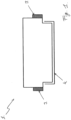
- Figure 1 shows a spacer 1 from the prior art with a substantially rectangular profile cross-section.
- a primary seal 3 is attached to the two narrow sides.
- Butyl compounds are usually used as the primary seal.
- the spacer 1 also has a vapor barrier 4.
- Aluminum, aluminum alloys, stainless steel or plastic films are usually used as the vapor barrier 4.
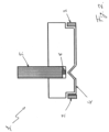
- Figure 2 shows another spacer 1 that is adapted for use with multi-glazed windows with three or more panes.
- the spacer 1 has a vapor barrier 4 and two primary seals 3 on the respective narrow sides of the spacer 1.
- the spacer also has a groove with another sealant 6, whereby acrylic adhesive or hot melts are generally used.
- a glass pane 5 is firmly connected to the spacer 1 in the groove by the seal 6.
- the spacer is also provided with a track groove that indicates the position of the groove.
- the track groove is used to position the spacer during the manufacture of insulating glass.
- the track groove is shown in conjunction with a conventionally manufactured spacer. It goes without saying that such track grooves are particularly easy to produce in conjunction with the coextruded or monoextruded spacers described below.
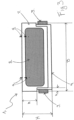
- FIG 3 shows a spacer 1 according to the invention with a thermoplastic casing 7 which encloses a drying agent 8.
- the spacer 1 has a casing 7 with a thickness of 1 mm.
- the spacer 1 has a height H of 6.5 mm, a height h of 3.5 mm, a width B of 9.8 mm and a width b of 0.8 mm.
- the spacer 1 also has a sputtered surface 4 which acts as a vapor barrier to prevent the passage of gas and water vapor.
- the narrow sides of the spacer 1 are provided with an acrylic elastomer (VAMAC; Typon) as a highly adhesive adhesive (positioning adhesive) 3.
- VAMAC acrylic elastomer
- the casing 7 also has perforations 9 on one side so that gas exchange can take place between the drying agent and the space between the panes (not shown).
- the sheath 7 consists of a flexible, hand-bendable thermoplastic elastomer.
- the elastomer has a Shore A hardness of over 60 ShA, is fogging-proof and diffusion-tight for water vapor and argon gas.
- the sheath 7 is particularly preferably made of the Saran product group and is co-extruded together with the desiccant matrix.
- the vapor barrier 4 for secondary sealing preferably consists of a composite functional film. Films sputtered with SiO 2 to make them diffusion-tight are particularly suitable. A laminate made of PE/PET-SiOx/PET-SiOx that is welded on after extrusion is particularly preferred, with the PE layer facing the spacer and the PET-SiOx layer facing the glass. Alternatively, EVOH-based films are conceivable. Alternatively, a glass, aluminum, stainless steel or plastic film can be glued on after the coextrusion of the casing 7 and the desiccant matrix 8. The primary seals (positioning adhesives) 3 can also be attached to the spacer 1 in an attached manufacturing step.
- the vapor barrier 4 can be a rolled metal foil that can be selected to be between 10 and 30 mm (aluminum) or 6 and 12 mm (stainless steel) thick, depending on the material used.
- the rolled films can also be corrugated. The corrugation is perpendicular to the longitudinal direction of the spacer. This makes the spacer more flexible and easier to roll up. Of course, in this case the plastic material applied to the film is also corrugated accordingly.
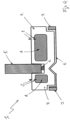
- FIG 4 shows an alternative embodiment to the spacer 1 from Figure 3
- the spacer 1 has a thermoplastic casing 7 made of Saran TM Barrier Films from DOW, which encloses a desiccant matrix 8 (as described above) in two separate chambers.
- a desiccant matrix 8 as described above
- the casing 7 is provided with perforations 9 at two locations 9 so that water vapor exchange is possible between the desiccant matrix and the space between the panes (not shown).
- Fig.4 shows a schematic of a middle pane 5 of a triple-glazed window, which is set into a groove and is firmly bonded to the spacer 1 by means of an adhesive 6.
- the spacer also has a track groove for positioning relative to the middle pane.
- the spacer 1 also has a vapor barrier 4.
- the vapor barrier preferably has a film coated with SiOx, e.g. a PET-SiOx film.
- a laminate made of PE/PET-SiOX/PET-SiOx from the manufacturer AMCOR is preferred.
- the PET-SiOx layer is a PET carrier that is coated with silicon in a high vacuum.
- vapor barriers made of a subsequently attached stainless steel film, aluminum rolled foil or another metal foil or vapor-deposited metal are also conceivable.
- the spacer also has two primary seals 3 made of an acrylic adhesive, which were also subsequently attached.
- TPU foam, butyl, hot melt or EPDM would also be suitable.
- the desiccant matrix used for Figure 3 and 4 3A zeolite with a volumetric content of 25 to 60% in a matrix of an olefin block copolymer (e.g. INFUSE TM 9700 from DOW ® ) or a polyolefin elastomer (e.g. ENGAGE TM from DOW ® ) is used.
- an olefin block copolymer e.g. INFUSE TM 9700 from DOW ®
- a polyolefin elastomer e.g. ENGAGE TM from DOW ®
- thermoplastic sheath 7 and the desiccant matrix 8 are coextruded in one process step.
- seal 6 can also be coextruded with the desiccant matrix 8 and the thermoplastic sheath 7.
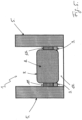
- FIG. 5 shows a spacer 1 mounted between two panes 5.
- the spacer 1 has a thermoplastic coating 7 in combination with a drying agent 8.
- the thermoplastic coating consists of TPU or olefins.
- the spacer also has an adhesive tape 11 on both sides, which was previously coated with a film and the film was removed before the spacer 1 was applied to the glass panes 5.
- the spacer 1 also has primary barriers 3 made of butyl adhesive.
- a secondary seal 10 made of polysulfide - Thiover or polyurethane - Polyver additionally seals the spacer 1 from the outside atmosphere.
- the drying agent 8 is extruded as a matrix made of drying agent and a plastic, whereby the materials of the Figures 3 and 4 be used.
- Figure 6 shows a spacer 1, in which, in contrast to the Figure 5 the adhesive tape and the primary barrier were replaced by a primary barrier 3 made of adhesive hot melt or butyl (adhesive).
- the primary barrier 3 thus performs a double function: bonding the glass panes and preventing vapor diffusion.
- the primary barrier 3 can be co-extruded with the other components of the spacer.
- Figure 6 (not shown in detail) similar to the Figures 2 or 3 a recess or a groove is provided (which is also already used in these figures to accommodate the primary seals 3.
- a recess in the case of a barrier foil
- a groove between the stainless steel foil and the profile
- the Figure 7 differs from the Figure 5 by a vapor barrier 4 welded to the thermoplastic elastomer 7, made of a SiOx-coated film or a glued film made of aluminum or stainless steel.
- the thermoplastic elastomer 7 encloses a drying agent 8.
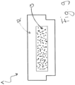
- Figure 8 shows a perspective cross-section of a section of a spacer 1 which is present as a strip cutout.
- the spacer 1 has a first flat base surface 20 which, when mounted, points towards a space between the panes (not shown) and a second flat base surface 21 which, when mounted, points towards a window frame (not shown).
- the spacer 1 has perforations 9 along the entire length of the side 20 in order to enable gas exchange with the drying agent.
- the base surface 21 is delimited by a diffusion-tight film.
- Figure 9 shows a perspective cross-section of a spacer 1, which is available as a strip cutout.
- the spacer 1 has an outer shell 12 and a porous inner structure 13.
- the outer shell 12 and the inner structure 13 are mono-extruded as a component compound from a plastic matrix and drying agent.
- the drying agent preferably used is zeolite and preferably makes up 50% of the drying agent matrix.
- the plastic for the matrix is Infuse 9007 from Dow.
- HTC8312/59 from KRAIBURG TPE Gmbh & Co. KG can also be used.
- This embodiment can also be used for triple glazing and can be provided with a track groove as described above.
- This embodiment can also be provided with adhesive tape and vapor barriers, in particular a vapor barrier made of a PE/PET-SiOx/PET-SiOx laminate film, as described above.
- Extrusion takes place at a temperature of 130°C (at the extrusion nozzle) to 160°C (in the feed line) and an extrusion speed of 5 to 30 m/min.
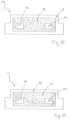
- Figure 10 shows a perspective cross-section of a spacer 1.
- the drying agent 8 has two cavities 14.
- the drying agent is surrounded by a casing 7.
- the drying agent 8 with the cavities 14 is coextruded with the casing 7.
- Figure 11 differs from Figure 10 in that the spacer 1 is mono-extruded as a whole from a plastic matrix.
- the spacer 1 has an outer shell 12 and an inner structure 13.
- the inner structure also has two cavities 14.
- the spacer outer skin also has a lower water vapor permeability. This significantly increases the service life of multi-glazed windows with the spacers according to the invention.
Landscapes
- Engineering & Computer Science (AREA)
- Structural Engineering (AREA)
- Civil Engineering (AREA)
- Architecture (AREA)
- Securing Of Glass Panes Or The Like (AREA)
- Joining Of Glass To Other Materials (AREA)
Priority Applications (1)
| Application Number | Priority Date | Filing Date | Title |
|---|---|---|---|
| PL15191282.1T PL3023569T5 (pl) | 2011-04-13 | 2012-04-10 | Element dystansowy do oddzielania szyb okna ze szkleniem wielokrotnym, okno ze szkleniem wielokrotnym i sposób wytwarzania elementu dystansowego |
Applications Claiming Priority (4)
| Application Number | Priority Date | Filing Date | Title |
|---|---|---|---|
| EP11162316 | 2011-04-13 | ||
| EP11196113 | 2011-12-29 | ||
| PCT/EP2012/056435 WO2012140005A1 (de) | 2011-04-13 | 2012-04-10 | Abstandhalter für die beabstandung von glasscheiben eines mehrfachverglasten fensters, ein mehrfachverglastes fenster, sowie ein verfahren zur herstellung eines abstandhalters |
| EP12714669.4A EP2697466A1 (de) | 2011-04-13 | 2012-04-10 | Abstandhalter für die beabstandung von glasscheiben eines mehrfachverglasten fensters, ein mehrfachverglastes fenster, sowie ein verfahren zur herstellung eines abstandhalters |
Related Parent Applications (1)
| Application Number | Title | Priority Date | Filing Date |
|---|---|---|---|
| EP12714669.4A Division EP2697466A1 (de) | 2011-04-13 | 2012-04-10 | Abstandhalter für die beabstandung von glasscheiben eines mehrfachverglasten fensters, ein mehrfachverglastes fenster, sowie ein verfahren zur herstellung eines abstandhalters |
Publications (3)
| Publication Number | Publication Date |
|---|---|
| EP3023569A1 EP3023569A1 (de) | 2016-05-25 |
| EP3023569B1 EP3023569B1 (de) | 2018-06-06 |
| EP3023569B2 true EP3023569B2 (de) | 2025-02-12 |
Family
ID=45974321
Family Applications (3)
| Application Number | Title | Priority Date | Filing Date |
|---|---|---|---|
| EP15191282.1A Active EP3023569B2 (de) | 2011-04-13 | 2012-04-10 | Abstandhalter für die beabstandung von glasscheiben eines mehrfachverglasten fensters |
| EP15200838.9A Revoked EP3020908B1 (de) | 2011-04-13 | 2012-04-10 | Abstandhalter für die beabstandung von glasscheiben eines mehrfachverglasten fensters |
| EP12714669.4A Withdrawn EP2697466A1 (de) | 2011-04-13 | 2012-04-10 | Abstandhalter für die beabstandung von glasscheiben eines mehrfachverglasten fensters, ein mehrfachverglastes fenster, sowie ein verfahren zur herstellung eines abstandhalters |
Family Applications After (2)
| Application Number | Title | Priority Date | Filing Date |
|---|---|---|---|
| EP15200838.9A Revoked EP3020908B1 (de) | 2011-04-13 | 2012-04-10 | Abstandhalter für die beabstandung von glasscheiben eines mehrfachverglasten fensters |
| EP12714669.4A Withdrawn EP2697466A1 (de) | 2011-04-13 | 2012-04-10 | Abstandhalter für die beabstandung von glasscheiben eines mehrfachverglasten fensters, ein mehrfachverglastes fenster, sowie ein verfahren zur herstellung eines abstandhalters |
Country Status (3)
| Country | Link |
|---|---|
| EP (3) | EP3023569B2 (pl) |
| PL (2) | PL3020908T3 (pl) |
| WO (1) | WO2012140005A1 (pl) |
Families Citing this family (19)
| Publication number | Priority date | Publication date | Assignee | Title |
|---|---|---|---|---|
| PL3020908T3 (pl) | 2011-04-13 | 2018-11-30 | Alu-Pro Srl | Element dystansowy do oddzielania szyb okna ze szkleniem wielokrotnym, okno ze szkleniem wielokrotnym i sposób wytwarzania elementu dystansowego |
| KR101672109B1 (ko) | 2012-01-13 | 2016-11-02 | 쌩-고벵 글래스 프랑스 | 단열 창유리 유닛용 스페이서 |
| EP3049603B1 (de) | 2013-09-25 | 2020-12-16 | ALU-PRO srl | Abstandhalter für die beabstandung von glasscheiben eines mehrfachverglasten fensters, mehrfachverglastes fenster, dampfsperrfolie für einen abstandhalter, verfahren zur herstellung einer dampfsperrfolie sowie verfahren zur herstellung eines abstandhalters |
| EP3080376A1 (de) | 2013-12-12 | 2016-10-19 | Saint-Gobain Glass France | Abstandshalter für isolierverglasungen mit extrudiertem dichtprofil |
| WO2015086457A2 (de) | 2013-12-12 | 2015-06-18 | Saint-Gobain Glass France | Isolierverglasung mit verbesserter abdichtung |
| US10301868B2 (en) | 2014-06-27 | 2019-05-28 | Saint-Gobain Glass France | Insulated glazing comprising a spacer, and production method |
| US10344525B2 (en) | 2014-06-27 | 2019-07-09 | Saint-Gobain Glass France | Insulated glazing with spacer, related methods and uses |
| DK3265636T3 (da) | 2015-03-02 | 2022-05-23 | Saint Gobain | Glasfiberforstærket afstandsholder til isoleringsrude, fremgangsmåde til fremstilling af denne og anvendelse af en sådan afstandsholder i flerlagsruder |
| CA2980680C (en) | 2015-04-22 | 2019-12-31 | Saint-Gobain Glass France | Method and device for producing a triple insulating glazing unit |
| USD777345S1 (en) | 2015-05-21 | 2017-01-24 | Saint-Gobain Glass France | Spacer bar |
| DE102016115023A1 (de) * | 2015-12-23 | 2017-06-29 | Ensinger Gmbh | Abstandhalter für Isolierglasscheiben |
| WO2018049176A1 (en) * | 2016-09-09 | 2018-03-15 | Andersen Corporation | High surface energy window spacer assemblies |
| WO2018050357A1 (de) | 2016-09-14 | 2018-03-22 | Saint-Gobain Glass France | Abstandshalter für isolierverglasungen, verfahren zur herstellung des abstandshalters und mehrfachisolierverglasung |
| EP3477035B1 (en) | 2017-10-30 | 2020-07-22 | Technoform Glass Insulation Holding GmbH | Spacer for photovoltaic applications |
| EP3505716A1 (en) | 2018-01-02 | 2019-07-03 | Amcor Flexibles Denmark ApS | Barrier window spacer with enhanced durability |
| WO2020053082A1 (de) | 2018-09-13 | 2020-03-19 | Saint-Gobain Glass France | Abstandhalter mit metallischen seitenteilen |
| WO2020200621A1 (de) | 2019-03-29 | 2020-10-08 | Saint-Gobain Glass France | Hohlprofilabstandhalter mit vorapplizierter abdichtmasse |
| WO2020200622A1 (de) | 2019-03-29 | 2020-10-08 | Saint-Gobain Glass France | Verfahren zur herstellung einer isolierglaseinheit |
| EP3770369A1 (de) | 2019-07-23 | 2021-01-27 | Saint-Gobain Glass France | Lagervorrichtung für hohlprofilabstandhalter |
Citations (6)
| Publication number | Priority date | Publication date | Assignee | Title |
|---|---|---|---|---|
| US5830545A (en) † | 1996-04-29 | 1998-11-03 | Tetra Laval Holdings & Finance, S.A. | Multilayer, high barrier laminate |
| EP1029661A1 (de) † | 1999-02-17 | 2000-08-23 | Alusuisse Technology & Management AG | Verbundfolie und Verfahren zu ihrer Herstellung |
| WO2004081331A1 (de) † | 2003-03-14 | 2004-09-23 | Ensinger Kunststofftechnologie Gbr | Abstandhalterprofil für isolierglasscheiben |
| DE10356216A1 (de) † | 2003-12-02 | 2005-07-14 | Usd Formteiltechnik Gmbh | Isolierglaseinheit |
| DE102004031203A1 (de) † | 2004-06-28 | 2006-01-19 | Wipak Walsrode Gmbh & Co. Kg | Siegelbare Verbundfolie und deren Verwendung zur Herstellung eines Schlauchbeutels |
| WO2008022877A1 (de) † | 2006-08-25 | 2008-02-28 | Prowerb St. Gallen Ag | Verfahren zur herstellung einer isolierglasscheibe sowie eine vorrichtung zum applizieren eines abstandhalters auf eine glasscheibe |
Family Cites Families (15)
| Publication number | Priority date | Publication date | Assignee | Title |
|---|---|---|---|---|
| DE3302659A1 (de) | 1983-01-27 | 1984-08-02 | Reichstadt, Hans Udo, 5628 Heiligenhaus | Abstandhalteprofil fuer mehrscheiben-isolierglas |
| CA1285177C (en) | 1986-09-22 | 1991-06-25 | Michael Glover | Multiple pane sealed glazing unit |
| US6528131B1 (en) * | 1991-04-22 | 2003-03-04 | Luc Lafond | Insulated assembly incorporating a thermoplastic barrier member |
| CH683853A5 (de) | 1991-08-27 | 1994-05-31 | Glas Troesch Ag St Gallen | Isolierverglasung. |
| DE19530838A1 (de) | 1995-08-22 | 1997-02-27 | Interpane Entw & Beratungsges | Abstandshalter für Isolierscheibenanordnung |
| JPH09175843A (ja) | 1995-12-27 | 1997-07-08 | Asahi Glass Co Ltd | 複層ガラスおよびそれに用いるスペーサ |
| DE19602455A1 (de) | 1996-01-24 | 1997-07-31 | Andreas Jakob | Innenleiste für gasgefüllte Mehrscheibenisolierverglasungen |
| US5851609A (en) | 1996-02-27 | 1998-12-22 | Truseal Technologies, Inc. | Preformed flexible laminate |
| DE19625845A1 (de) | 1996-06-27 | 1998-01-02 | Flachglas Ag | Isolierglaseinheit |
| DE19807454A1 (de) | 1998-02-21 | 1999-08-26 | Ensinger | Abstandhalter |
| AU1625900A (en) * | 1998-11-16 | 2000-06-05 | Edgetech I.G., Inc. | Insulating glazing unit using a foamed sealant and method for manufacturing the same |
| DE102006024402B4 (de) | 2006-05-24 | 2008-01-03 | Peter Lisec | Isolierglaseinheit mit einem elastoplastischen Abstandhalterband und Applizzierverfahren für letzteres |
| US7804274B2 (en) | 2008-07-21 | 2010-09-28 | Coulomb Technologies, Inc. | Vehicle charging station having a dual position locking door |
| CN102388197B (zh) * | 2009-04-07 | 2014-12-24 | 普罗沃博圣加伦股份公司 | 间隔复合玻璃板的玻璃的间隔垫块、复合玻璃板及其制造方法 |
| PL3020908T3 (pl) | 2011-04-13 | 2018-11-30 | Alu-Pro Srl | Element dystansowy do oddzielania szyb okna ze szkleniem wielokrotnym, okno ze szkleniem wielokrotnym i sposób wytwarzania elementu dystansowego |
-
2012
- 2012-04-10 PL PL15200838T patent/PL3020908T3/pl unknown
- 2012-04-10 WO PCT/EP2012/056435 patent/WO2012140005A1/de not_active Ceased
- 2012-04-10 EP EP15191282.1A patent/EP3023569B2/de active Active
- 2012-04-10 PL PL15191282.1T patent/PL3023569T5/pl unknown
- 2012-04-10 EP EP15200838.9A patent/EP3020908B1/de not_active Revoked
- 2012-04-10 EP EP12714669.4A patent/EP2697466A1/de not_active Withdrawn
Patent Citations (6)
| Publication number | Priority date | Publication date | Assignee | Title |
|---|---|---|---|---|
| US5830545A (en) † | 1996-04-29 | 1998-11-03 | Tetra Laval Holdings & Finance, S.A. | Multilayer, high barrier laminate |
| EP1029661A1 (de) † | 1999-02-17 | 2000-08-23 | Alusuisse Technology & Management AG | Verbundfolie und Verfahren zu ihrer Herstellung |
| WO2004081331A1 (de) † | 2003-03-14 | 2004-09-23 | Ensinger Kunststofftechnologie Gbr | Abstandhalterprofil für isolierglasscheiben |
| DE10356216A1 (de) † | 2003-12-02 | 2005-07-14 | Usd Formteiltechnik Gmbh | Isolierglaseinheit |
| DE102004031203A1 (de) † | 2004-06-28 | 2006-01-19 | Wipak Walsrode Gmbh & Co. Kg | Siegelbare Verbundfolie und deren Verwendung zur Herstellung eines Schlauchbeutels |
| WO2008022877A1 (de) † | 2006-08-25 | 2008-02-28 | Prowerb St. Gallen Ag | Verfahren zur herstellung einer isolierglasscheibe sowie eine vorrichtung zum applizieren eines abstandhalters auf eine glasscheibe |
Also Published As
| Publication number | Publication date |
|---|---|
| EP3020908A1 (de) | 2016-05-18 |
| WO2012140005A1 (de) | 2012-10-18 |
| PL3023569T5 (pl) | 2025-05-05 |
| EP3020908B1 (de) | 2018-06-06 |
| PL3023569T3 (pl) | 2018-11-30 |
| EP3023569B1 (de) | 2018-06-06 |
| EP3023569A1 (de) | 2016-05-25 |
| EP2697466A1 (de) | 2014-02-19 |
| PL3020908T3 (pl) | 2018-11-30 |
Similar Documents
| Publication | Publication Date | Title |
|---|---|---|
| EP3023569B2 (de) | Abstandhalter für die beabstandung von glasscheiben eines mehrfachverglasten fensters | |
| EP3052731B2 (de) | Abstandshalter für isolierverglasungen | |
| EP2906424B1 (de) | Isolierverglasungseinheit | |
| EP2526247B1 (de) | Randverbundklammer für isolierglaseinheit, randverbund einer isolierglaseinheit, isolierglaseinheit mit randverbundklammer | |
| EP3421709B1 (de) | Abstandshalter für isolierverglasungen | |
| EP2513401B1 (de) | Abstandshalterprofil und isolierscheibeneinheit mit einem solchen abstandshalterprofil | |
| DE3871939T2 (de) | Mehrfachverglasung. | |
| EP3161237B1 (de) | Isolierverglasung mit abstandhalter und verfahren zur herstellung einer solchen sowie deren verwendung als gebäudeverglasung | |
| EP3230546A1 (de) | Abstandshalter für isolierverglasungen | |
| WO2021008951A1 (de) | Abstandhalter für isolierglaseinheiten | |
| EP3049603B1 (de) | Abstandhalter für die beabstandung von glasscheiben eines mehrfachverglasten fensters, mehrfachverglastes fenster, dampfsperrfolie für einen abstandhalter, verfahren zur herstellung einer dampfsperrfolie sowie verfahren zur herstellung eines abstandhalters | |
| EP3999709B1 (de) | Abstandhalter für isolierglaseinheiten | |
| EP3850180A1 (de) | Abstandhalter mit metallischen seitenteilen | |
| EP3362630A1 (de) | Verbinder zur verbindung von zwei hohlprofilleisten | |
| EP3464771B1 (de) | Isolierverglasung mit erhöhter durchbruchhemmung und u-förmigem aufnahmeprofil | |
| EP3708759A1 (de) | Isolierverglasungsgrundkörper und isolierverglasung, sowie verfahren zu deren herstellung | |
| EP2295697A2 (de) | Verfahren zum Herstellen eines Fensters oder einer Tür | |
| WO2017207192A1 (de) | Isolierverglasung mit erhöhter durchbruchhemmung | |
| DE202023002879U1 (de) | Abstandshalter mit verbesserter mechanischer Steifigkeit | |
| EP3938609A1 (de) | Isolierverglasung mit verbesserter positionierung des abstandhalters sowie verfahren zu deren herstellung | |
| WO2020200622A1 (de) | Verfahren zur herstellung einer isolierglaseinheit | |
| WO2020200621A1 (de) | Hohlprofilabstandhalter mit vorapplizierter abdichtmasse | |
| EP3770369A1 (de) | Lagervorrichtung für hohlprofilabstandhalter |
Legal Events
| Date | Code | Title | Description |
|---|---|---|---|
| AC | Divisional application: reference to earlier application |
Ref document number: 2697466 Country of ref document: EP Kind code of ref document: P |
|
| AK | Designated contracting states |
Kind code of ref document: A1 Designated state(s): AL AT BE BG CH CY CZ DE DK EE ES FI FR GB GR HR HU IE IS IT LI LT LU LV MC MK MT NL NO PL PT RO RS SE SI SK SM TR |
|
| PUAI | Public reference made under article 153(3) epc to a published international application that has entered the european phase |
Free format text: ORIGINAL CODE: 0009012 |
|
| STAA | Information on the status of an ep patent application or granted ep patent |
Free format text: STATUS: REQUEST FOR EXAMINATION WAS MADE |
|
| 17P | Request for examination filed |
Effective date: 20161122 |
|
| RBV | Designated contracting states (corrected) |
Designated state(s): AL AT BE BG CH CY CZ DE DK EE ES FI FR GB GR HR HU IE IS IT LI LT LU LV MC MK MT NL NO PL PT RO RS SE SI SK SM TR |
|
| STAA | Information on the status of an ep patent application or granted ep patent |
Free format text: STATUS: EXAMINATION IS IN PROGRESS |
|
| 17Q | First examination report despatched |
Effective date: 20170406 |
|
| GRAP | Despatch of communication of intention to grant a patent |
Free format text: ORIGINAL CODE: EPIDOSNIGR1 |
|
| STAA | Information on the status of an ep patent application or granted ep patent |
Free format text: STATUS: GRANT OF PATENT IS INTENDED |
|
| INTG | Intention to grant announced |
Effective date: 20171124 |
|
| GRAS | Grant fee paid |
Free format text: ORIGINAL CODE: EPIDOSNIGR3 |
|
| GRAA | (expected) grant |
Free format text: ORIGINAL CODE: 0009210 |
|
| STAA | Information on the status of an ep patent application or granted ep patent |
Free format text: STATUS: THE PATENT HAS BEEN GRANTED |
|
| AC | Divisional application: reference to earlier application |
Ref document number: 2697466 Country of ref document: EP Kind code of ref document: P |
|
| AK | Designated contracting states |
Kind code of ref document: B1 Designated state(s): AL AT BE BG CH CY CZ DE DK EE ES FI FR GB GR HR HU IE IS IT LI LT LU LV MC MK MT NL NO PL PT RO RS SE SI SK SM TR |
|
| REG | Reference to a national code |
Ref country code: GB Ref legal event code: FG4D Free format text: NOT ENGLISH |
|
| REG | Reference to a national code |
Ref country code: CH Ref legal event code: EP Ref country code: AT Ref legal event code: REF Ref document number: 1006283 Country of ref document: AT Kind code of ref document: T Effective date: 20180615 |
|
| REG | Reference to a national code |
Ref country code: IE Ref legal event code: FG4D Free format text: LANGUAGE OF EP DOCUMENT: GERMAN |
|
| REG | Reference to a national code |
Ref country code: DE Ref legal event code: R096 Ref document number: 502012012849 Country of ref document: DE |
|
| REG | Reference to a national code |
Ref country code: NL Ref legal event code: MP Effective date: 20180606 |
|
| REG | Reference to a national code |
Ref country code: LT Ref legal event code: MG4D |
|
| PG25 | Lapsed in a contracting state [announced via postgrant information from national office to epo] |
Ref country code: SE Free format text: LAPSE BECAUSE OF FAILURE TO SUBMIT A TRANSLATION OF THE DESCRIPTION OR TO PAY THE FEE WITHIN THE PRESCRIBED TIME-LIMIT Effective date: 20180606 Ref country code: LT Free format text: LAPSE BECAUSE OF FAILURE TO SUBMIT A TRANSLATION OF THE DESCRIPTION OR TO PAY THE FEE WITHIN THE PRESCRIBED TIME-LIMIT Effective date: 20180606 Ref country code: ES Free format text: LAPSE BECAUSE OF FAILURE TO SUBMIT A TRANSLATION OF THE DESCRIPTION OR TO PAY THE FEE WITHIN THE PRESCRIBED TIME-LIMIT Effective date: 20180606 Ref country code: FI Free format text: LAPSE BECAUSE OF FAILURE TO SUBMIT A TRANSLATION OF THE DESCRIPTION OR TO PAY THE FEE WITHIN THE PRESCRIBED TIME-LIMIT Effective date: 20180606 Ref country code: NO Free format text: LAPSE BECAUSE OF FAILURE TO SUBMIT A TRANSLATION OF THE DESCRIPTION OR TO PAY THE FEE WITHIN THE PRESCRIBED TIME-LIMIT Effective date: 20180906 Ref country code: CY Free format text: LAPSE BECAUSE OF FAILURE TO SUBMIT A TRANSLATION OF THE DESCRIPTION OR TO PAY THE FEE WITHIN THE PRESCRIBED TIME-LIMIT Effective date: 20180606 Ref country code: BG Free format text: LAPSE BECAUSE OF FAILURE TO SUBMIT A TRANSLATION OF THE DESCRIPTION OR TO PAY THE FEE WITHIN THE PRESCRIBED TIME-LIMIT Effective date: 20180906 |
|
| PG25 | Lapsed in a contracting state [announced via postgrant information from national office to epo] |
Ref country code: RS Free format text: LAPSE BECAUSE OF FAILURE TO SUBMIT A TRANSLATION OF THE DESCRIPTION OR TO PAY THE FEE WITHIN THE PRESCRIBED TIME-LIMIT Effective date: 20180606 Ref country code: LV Free format text: LAPSE BECAUSE OF FAILURE TO SUBMIT A TRANSLATION OF THE DESCRIPTION OR TO PAY THE FEE WITHIN THE PRESCRIBED TIME-LIMIT Effective date: 20180606 Ref country code: GR Free format text: LAPSE BECAUSE OF FAILURE TO SUBMIT A TRANSLATION OF THE DESCRIPTION OR TO PAY THE FEE WITHIN THE PRESCRIBED TIME-LIMIT Effective date: 20180907 Ref country code: HR Free format text: LAPSE BECAUSE OF FAILURE TO SUBMIT A TRANSLATION OF THE DESCRIPTION OR TO PAY THE FEE WITHIN THE PRESCRIBED TIME-LIMIT Effective date: 20180606 |
|
| PG25 | Lapsed in a contracting state [announced via postgrant information from national office to epo] |
Ref country code: NL Free format text: LAPSE BECAUSE OF FAILURE TO SUBMIT A TRANSLATION OF THE DESCRIPTION OR TO PAY THE FEE WITHIN THE PRESCRIBED TIME-LIMIT Effective date: 20180606 |
|
| PG25 | Lapsed in a contracting state [announced via postgrant information from national office to epo] |
Ref country code: SK Free format text: LAPSE BECAUSE OF FAILURE TO SUBMIT A TRANSLATION OF THE DESCRIPTION OR TO PAY THE FEE WITHIN THE PRESCRIBED TIME-LIMIT Effective date: 20180606 Ref country code: EE Free format text: LAPSE BECAUSE OF FAILURE TO SUBMIT A TRANSLATION OF THE DESCRIPTION OR TO PAY THE FEE WITHIN THE PRESCRIBED TIME-LIMIT Effective date: 20180606 Ref country code: IS Free format text: LAPSE BECAUSE OF FAILURE TO SUBMIT A TRANSLATION OF THE DESCRIPTION OR TO PAY THE FEE WITHIN THE PRESCRIBED TIME-LIMIT Effective date: 20181006 Ref country code: RO Free format text: LAPSE BECAUSE OF FAILURE TO SUBMIT A TRANSLATION OF THE DESCRIPTION OR TO PAY THE FEE WITHIN THE PRESCRIBED TIME-LIMIT Effective date: 20180606 |
|
| PG25 | Lapsed in a contracting state [announced via postgrant information from national office to epo] |
Ref country code: SM Free format text: LAPSE BECAUSE OF FAILURE TO SUBMIT A TRANSLATION OF THE DESCRIPTION OR TO PAY THE FEE WITHIN THE PRESCRIBED TIME-LIMIT Effective date: 20180606 |
|
| REG | Reference to a national code |
Ref country code: DE Ref legal event code: R026 Ref document number: 502012012849 Country of ref document: DE |
|
| PLBI | Opposition filed |
Free format text: ORIGINAL CODE: 0009260 |
|
| PLAX | Notice of opposition and request to file observation + time limit sent |
Free format text: ORIGINAL CODE: EPIDOSNOBS2 |
|
| 26 | Opposition filed |
Opponent name: TECHNOFORM GLASS INSULATION HOLDING GMBH Effective date: 20190301 |
|
| PG25 | Lapsed in a contracting state [announced via postgrant information from national office to epo] |
Ref country code: DK Free format text: LAPSE BECAUSE OF FAILURE TO SUBMIT A TRANSLATION OF THE DESCRIPTION OR TO PAY THE FEE WITHIN THE PRESCRIBED TIME-LIMIT Effective date: 20180606 Ref country code: SI Free format text: LAPSE BECAUSE OF FAILURE TO SUBMIT A TRANSLATION OF THE DESCRIPTION OR TO PAY THE FEE WITHIN THE PRESCRIBED TIME-LIMIT Effective date: 20180606 |
|
| PLBB | Reply of patent proprietor to notice(s) of opposition received |
Free format text: ORIGINAL CODE: EPIDOSNOBS3 |
|
| PG25 | Lapsed in a contracting state [announced via postgrant information from national office to epo] |
Ref country code: AL Free format text: LAPSE BECAUSE OF FAILURE TO SUBMIT A TRANSLATION OF THE DESCRIPTION OR TO PAY THE FEE WITHIN THE PRESCRIBED TIME-LIMIT Effective date: 20180606 |
|
| REG | Reference to a national code |
Ref country code: CH Ref legal event code: PL |
|
| REG | Reference to a national code |
Ref country code: BE Ref legal event code: MM Effective date: 20190430 |
|
| GBPC | Gb: european patent ceased through non-payment of renewal fee |
Effective date: 20190410 |
|
| PG25 | Lapsed in a contracting state [announced via postgrant information from national office to epo] |
Ref country code: LU Free format text: LAPSE BECAUSE OF NON-PAYMENT OF DUE FEES Effective date: 20190410 Ref country code: MC Free format text: LAPSE BECAUSE OF FAILURE TO SUBMIT A TRANSLATION OF THE DESCRIPTION OR TO PAY THE FEE WITHIN THE PRESCRIBED TIME-LIMIT Effective date: 20180606 |
|
| PG25 | Lapsed in a contracting state [announced via postgrant information from national office to epo] |
Ref country code: GB Free format text: LAPSE BECAUSE OF NON-PAYMENT OF DUE FEES Effective date: 20190410 Ref country code: LI Free format text: LAPSE BECAUSE OF NON-PAYMENT OF DUE FEES Effective date: 20190430 Ref country code: CH Free format text: LAPSE BECAUSE OF NON-PAYMENT OF DUE FEES Effective date: 20190430 |
|
| PG25 | Lapsed in a contracting state [announced via postgrant information from national office to epo] |
Ref country code: BE Free format text: LAPSE BECAUSE OF NON-PAYMENT OF DUE FEES Effective date: 20190430 |
|
| PG25 | Lapsed in a contracting state [announced via postgrant information from national office to epo] |
Ref country code: TR Free format text: LAPSE BECAUSE OF FAILURE TO SUBMIT A TRANSLATION OF THE DESCRIPTION OR TO PAY THE FEE WITHIN THE PRESCRIBED TIME-LIMIT Effective date: 20180606 |
|
| PG25 | Lapsed in a contracting state [announced via postgrant information from national office to epo] |
Ref country code: IE Free format text: LAPSE BECAUSE OF NON-PAYMENT OF DUE FEES Effective date: 20190410 |
|
| PG25 | Lapsed in a contracting state [announced via postgrant information from national office to epo] |
Ref country code: PT Free format text: LAPSE BECAUSE OF FAILURE TO SUBMIT A TRANSLATION OF THE DESCRIPTION OR TO PAY THE FEE WITHIN THE PRESCRIBED TIME-LIMIT Effective date: 20181008 |
|
| REG | Reference to a national code |
Ref country code: AT Ref legal event code: MM01 Ref document number: 1006283 Country of ref document: AT Kind code of ref document: T Effective date: 20190410 |
|
| PG25 | Lapsed in a contracting state [announced via postgrant information from national office to epo] |
Ref country code: AT Free format text: LAPSE BECAUSE OF NON-PAYMENT OF DUE FEES Effective date: 20190410 |
|
| PG25 | Lapsed in a contracting state [announced via postgrant information from national office to epo] |
Ref country code: MT Free format text: LAPSE BECAUSE OF FAILURE TO SUBMIT A TRANSLATION OF THE DESCRIPTION OR TO PAY THE FEE WITHIN THE PRESCRIBED TIME-LIMIT Effective date: 20180606 Ref country code: HU Free format text: LAPSE BECAUSE OF FAILURE TO SUBMIT A TRANSLATION OF THE DESCRIPTION OR TO PAY THE FEE WITHIN THE PRESCRIBED TIME-LIMIT; INVALID AB INITIO Effective date: 20120410 |
|
| APBM | Appeal reference recorded |
Free format text: ORIGINAL CODE: EPIDOSNREFNO |
|
| APBP | Date of receipt of notice of appeal recorded |
Free format text: ORIGINAL CODE: EPIDOSNNOA2O |
|
| APAH | Appeal reference modified |
Free format text: ORIGINAL CODE: EPIDOSCREFNO |
|
| APBM | Appeal reference recorded |
Free format text: ORIGINAL CODE: EPIDOSNREFNO |
|
| APBP | Date of receipt of notice of appeal recorded |
Free format text: ORIGINAL CODE: EPIDOSNNOA2O |
|
| APBQ | Date of receipt of statement of grounds of appeal recorded |
Free format text: ORIGINAL CODE: EPIDOSNNOA3O |
|
| APBQ | Date of receipt of statement of grounds of appeal recorded |
Free format text: ORIGINAL CODE: EPIDOSNNOA3O |
|
| PLAB | Opposition data, opponent's data or that of the opponent's representative modified |
Free format text: ORIGINAL CODE: 0009299OPPO |
|
| R26 | Opposition filed (corrected) |
Opponent name: TECHNOFORM GLASS INSULATION HOLDING GMBH Effective date: 20190301 |
|
| PG25 | Lapsed in a contracting state [announced via postgrant information from national office to epo] |
Ref country code: MK Free format text: LAPSE BECAUSE OF FAILURE TO SUBMIT A TRANSLATION OF THE DESCRIPTION OR TO PAY THE FEE WITHIN THE PRESCRIBED TIME-LIMIT Effective date: 20180606 |
|
| P01 | Opt-out of the competence of the unified patent court (upc) registered |
Effective date: 20230601 |
|
| APAH | Appeal reference modified |
Free format text: ORIGINAL CODE: EPIDOSCREFNO |
|
| APBU | Appeal procedure closed |
Free format text: ORIGINAL CODE: EPIDOSNNOA9O |
|
| PUAH | Patent maintained in amended form |
Free format text: ORIGINAL CODE: 0009272 |
|
| STAA | Information on the status of an ep patent application or granted ep patent |
Free format text: STATUS: PATENT MAINTAINED AS AMENDED |
|
| 27A | Patent maintained in amended form |
Effective date: 20250212 |
|
| AK | Designated contracting states |
Kind code of ref document: B2 Designated state(s): AL AT BE BG CH CY CZ DE DK EE ES FI FR GB GR HR HU IE IS IT LI LT LU LV MC MK MT NL NO PL PT RO RS SE SI SK SM TR |
|
| REG | Reference to a national code |
Ref country code: DE Ref legal event code: R102 Ref document number: 502012012849 Country of ref document: DE |
|
| PGFP | Annual fee paid to national office [announced via postgrant information from national office to epo] |
Ref country code: FR Payment date: 20250327 Year of fee payment: 14 Ref country code: CZ Payment date: 20250324 Year of fee payment: 14 |
|
| PGFP | Annual fee paid to national office [announced via postgrant information from national office to epo] |
Ref country code: PL Payment date: 20250323 Year of fee payment: 14 Ref country code: DE Payment date: 20250320 Year of fee payment: 14 |
|
| PGFP | Annual fee paid to national office [announced via postgrant information from national office to epo] |
Ref country code: IT Payment date: 20250320 Year of fee payment: 14 |