EP3020906B1 - Antriebsvorrichtung für eine schiebetür und bausatz zum ausrüsten einer fassade mit einer solchen vorrichtung - Google Patents
Antriebsvorrichtung für eine schiebetür und bausatz zum ausrüsten einer fassade mit einer solchen vorrichtung Download PDFInfo
- Publication number
- EP3020906B1 EP3020906B1 EP15190070.1A EP15190070A EP3020906B1 EP 3020906 B1 EP3020906 B1 EP 3020906B1 EP 15190070 A EP15190070 A EP 15190070A EP 3020906 B1 EP3020906 B1 EP 3020906B1
- Authority
- EP
- European Patent Office
- Prior art keywords
- support
- operating apparatus
- opening
- frame
- fixed
- Prior art date
- Legal status (The legal status is an assumption and is not a legal conclusion. Google has not performed a legal analysis and makes no representation as to the accuracy of the status listed.)
- Active
Links
- 238000009792 diffusion process Methods 0.000 claims description 8
- 230000005855 radiation Effects 0.000 claims description 6
- 238000009304 pastoral farming Methods 0.000 claims description 3
- 238000005266 casting Methods 0.000 claims description 2
- 230000000007 visual effect Effects 0.000 description 4
- 230000000694 effects Effects 0.000 description 3
- 238000004873 anchoring Methods 0.000 description 2
- 239000011521 glass Substances 0.000 description 2
- 230000010354 integration Effects 0.000 description 2
- 230000000981 bystander Effects 0.000 description 1
- 238000010276 construction Methods 0.000 description 1
- 230000008878 coupling Effects 0.000 description 1
- 238000010168 coupling process Methods 0.000 description 1
- 238000005859 coupling reaction Methods 0.000 description 1
- 230000001419 dependent effect Effects 0.000 description 1
- 238000005286 illumination Methods 0.000 description 1
- 238000009434 installation Methods 0.000 description 1
- 239000000463 material Substances 0.000 description 1
- 238000000034 method Methods 0.000 description 1
- 238000012986 modification Methods 0.000 description 1
- 230000004048 modification Effects 0.000 description 1
- 230000008447 perception Effects 0.000 description 1
- 238000009423 ventilation Methods 0.000 description 1
Images


Classifications
-
- E—FIXED CONSTRUCTIONS
- E05—LOCKS; KEYS; WINDOW OR DOOR FITTINGS; SAFES
- E05F—DEVICES FOR MOVING WINGS INTO OPEN OR CLOSED POSITION; CHECKS FOR WINGS; WING FITTINGS NOT OTHERWISE PROVIDED FOR, CONCERNED WITH THE FUNCTIONING OF THE WING
- E05F15/00—Power-operated mechanisms for wings
- E05F15/60—Power-operated mechanisms for wings using electrical actuators
- E05F15/603—Power-operated mechanisms for wings using electrical actuators using rotary electromotors
- E05F15/632—Power-operated mechanisms for wings using electrical actuators using rotary electromotors for horizontally-sliding wings
-
- E—FIXED CONSTRUCTIONS
- E05—LOCKS; KEYS; WINDOW OR DOOR FITTINGS; SAFES
- E05D—HINGES OR SUSPENSION DEVICES FOR DOORS, WINDOWS OR WINGS
- E05D15/00—Suspension arrangements for wings
- E05D15/06—Suspension arrangements for wings for wings sliding horizontally more or less in their own plane
- E05D15/0621—Details, e.g. suspension or supporting guides
- E05D15/0626—Details, e.g. suspension or supporting guides for wings suspended at the top
- E05D15/0652—Tracks
-
- E—FIXED CONSTRUCTIONS
- E05—LOCKS; KEYS; WINDOW OR DOOR FITTINGS; SAFES
- E05Y—INDEXING SCHEME ASSOCIATED WITH SUBCLASSES E05D AND E05F, RELATING TO CONSTRUCTION ELEMENTS, ELECTRIC CONTROL, POWER SUPPLY, POWER SIGNAL OR TRANSMISSION, USER INTERFACES, MOUNTING OR COUPLING, DETAILS, ACCESSORIES, AUXILIARY OPERATIONS NOT OTHERWISE PROVIDED FOR, APPLICATION THEREOF
- E05Y2201/00—Constructional elements; Accessories therefor
- E05Y2201/10—Covers; Housings
- E05Y2201/11—Covers
-
- E—FIXED CONSTRUCTIONS
- E05—LOCKS; KEYS; WINDOW OR DOOR FITTINGS; SAFES
- E05Y—INDEXING SCHEME ASSOCIATED WITH SUBCLASSES E05D AND E05F, RELATING TO CONSTRUCTION ELEMENTS, ELECTRIC CONTROL, POWER SUPPLY, POWER SIGNAL OR TRANSMISSION, USER INTERFACES, MOUNTING OR COUPLING, DETAILS, ACCESSORIES, AUXILIARY OPERATIONS NOT OTHERWISE PROVIDED FOR, APPLICATION THEREOF
- E05Y2800/00—Details, accessories and auxiliary operations not otherwise provided for
- E05Y2800/10—Additional functions
- E05Y2800/106—Lighting
-
- E—FIXED CONSTRUCTIONS
- E05—LOCKS; KEYS; WINDOW OR DOOR FITTINGS; SAFES
- E05Y—INDEXING SCHEME ASSOCIATED WITH SUBCLASSES E05D AND E05F, RELATING TO CONSTRUCTION ELEMENTS, ELECTRIC CONTROL, POWER SUPPLY, POWER SIGNAL OR TRANSMISSION, USER INTERFACES, MOUNTING OR COUPLING, DETAILS, ACCESSORIES, AUXILIARY OPERATIONS NOT OTHERWISE PROVIDED FOR, APPLICATION THEREOF
- E05Y2900/00—Application of doors, windows, wings or fittings thereof
- E05Y2900/10—Application of doors, windows, wings or fittings thereof for buildings or parts thereof
- E05Y2900/13—Type of wing
- E05Y2900/132—Doors
Definitions
- the present invention relates to an apparatus for operating a sliding door and a kit for equipping a facade which comprises such an apparatus.
- the present invention relates to an apparatus for operating a sliding door intended to be installed on walls not already adapted to carry a sliding door, and a kit to equip the facade of that wall.
- the present invention is in the field of auxiliary structures for buildings.
- this traditional system presents the casing that protrude from the wall facade wherein one leaf or two leaves of the door hang below the casing. It is clear that such operating device must extend for the entire movement path of the leaf and then, with respect to the area which the door is intended to close, extends the entire length of the leaf, on one side of the compartment, if the door is a single-leaf door or, if the door is a two-leaf door extends on both sides of the compartment of a length at least equal to that of each leaf.
- the resulting aesthetic effect of the casing is that of a bulky item and disproportionate to the opening. Generally, the aesthetic effect of these traditional devices is not liked at all.
- the problem underlying the present invention is to propose an apparatus for actuating a sliding door which present a visual impact less bulky than the traditional devices.
- An aim of the present invention is to provide an apparatus for actuating a sliding door and a kit for equipping facades which solves this problem by overcoming the drawbacks of the traditionals operating apparatuses described above.
- Another aim of the present invention is to provide an apparatus for operating a sliding door that, compared to the traditional ones, allows for greater integration with windows or accessories systems for windows and/or shop windows.
- Another object of the invention is to propose an apparatus for operating a sliding door which allows to integrate more effectively with ancillary structures of glasses and display walls.
- a further object of the present invention is to provide a kit for equipping a facade that allows to integrate easily and effectively a sliding door in a facade not suitable to have a compartment for sliding door.
- an apparatus for operating a sliding door comprising:
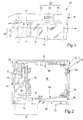
- the operating apparatus 10 has a particular characteristic in that it comprises lighting means 16 fixed to the frame 11 and configured such that, in a use condition in which the frame 11 is fixed to a vertical wall, the lighting means 16 are activated to project at least one light radiation that hits in a substantially grazing way the vertical wall.
- the illumination effect on a zone of the wall or facade adjacent to where the operating apparatus 10, thereby created, is that it is dramatically reduced the perception of the operating apparatus itself so as to greatly reduce the visual impact thereof compared to the conventional operating apparatuses.
- the operating apparatus 10 is configured in such a way that the lighting means 16 in use project at least one light radiation towards the sliding door and/or towards the facade on which the operating apparatus 10 is supported.
- the lighting means 16 are adapted to generate:
- the operating apparatus 10 develops mainly along the opening/closing direction A and includes:
- the lighting means 16 are configured so as to generate a light radiation directed from the inside towards the outside of the compartment B, in a direction at least predominantly parallel to the rear wall 17.
- the lighting means 16 in use illuminate in a substantially grazing way the facade on which the apparatus is installed and/or the opening of the door so as to make more relevant the visual impact of the illuminated area, and then draw on this the attention of a bystander and consequently further reduce the visual impact of the operating apparatus.
- the frame 11 includes advantageously the rear wall 17 and the upper wall 18, each provided with a face C and D respectively, that are external to the compartment B.
- These two external faces C and D preferably extend along mutually perpendicular planes, so that, when the operating apparatus is fixed to a vertical wall, by its rear wall 17, then the outer face D of the upper wall is horizontal.
- the support means 13 advantageously comprise at least one rail 20 fixed to the rear wall 17 or integral with the latter.
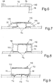
- the front wall 19 preferably includes a support 21 fixed to the upper wall 18, or integral with the latter and a hiding element 22 that can be fixed in a removable manner to the support 21 and adapted to conceal the contents of the compartment B.
- the hiding element 22 advantageously comprises:
- a hiding element 22 that have only two lateral elements, one on the right side and one on left side 25, 24, however, the present description is applicable mutatis mutandis to the case of a plurality of lateral elements 24 and 25.
- locking means adapted to lock the hiding element 22 to the support 21 are provided.
- These locking means 26 are configured so that the lateral elements 24, 25 are locked or unlocked to the support 21 by means of a sliding movement along a direction parallel to the opening/closing direction A.
- the locking means 26 are also configured in such a way that the central element 23 is lockable and unlockable to the support 21 along a direction perpendicular to the opening/closing direction A and that if the elements 23, 24, 25 are locked to the support 21, then the central element 23 prevents lateral elements 25, 26 an unlocking sliding along the opening/closing direction A, to keep them locked to the support 21 as long as the central element 23 is locked thereto.
- the locking means 26 comprise a bayonet type device of the type equipped with a mushroom-shaped anchoring member adapted to engage a lane by means of a movement that is first perpendicular to the opening/closing direction A, for coupling with the lane, and then parallel to the opening/closing direction A to engage the lane with the head of the anchoring device.
- the lighting means 16 advantageously comprise a device for light diffusion 27 shaped to form a light band, extending parallel to the opening/closing direction A.
- the light diffusion device 27 advantageously comprises:
- the light diffusion device 27 is fixed to or integral with the front wall 19, and delimits, in cooperation with the rear wall 17 and a bottom opening E of the compartment B through which a leaf 14 of the sliding door can protrude from the operating apparatus 10.
- the light diffusion device 27 protrudes from the front wall 19 towards the rear wall 17 and by its own free edge defines a side of the lower opening, the other side of the latter being defined by the rear wall 17.
- the free edge of the light diffusion device 27 carries a yielding element, for example a brush, adapted to close a portion of the lower opening E which is free from the leaf 14 when this is hanged to the support means 13.
- a yielding element for example a brush
- the lighting means 16 preferably comprise spotlights adapted to emit focused light beams.
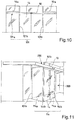
- kit 100 to equip a facade with a sliding door, which comprises an operating apparatus 10.
- the kit 100 comprises support elements 101, which can be fixed to the operating apparatus 10 so as to extend transversely and/or parallel to the opening/closing direction A and suitable for being affixed to a floor and/or ceiling and/or vertical walls of a building and configured to support the operating apparatus 10.
- the support elements 101 include bearing beams preferably equipped with a cover.
- the support elements 101 are preferably configured to form an H-shaped structure comprising a central beam 101a that extends horizontally between two walls, and two uprights 101b and 101c which extend from a floor to a ceiling.
- a self-supporting structure which includes the operating device 10 which may comprise in central part of the support means 13 to operate the leaves 14 of a door and, in the side parts 10a such as spotlights and/or tends to respectively illuminate or cover an exhibition zone as a shop window 102.
- the kit 100 is advantageously modular and comprises a plurality of modular elements having a flat face that can be fixed to a vertical support and having all the same cross section, relative to a plane perpendicular to said planar face.
- Said plurality of modules 110, 111, 112, 113 preferably comprises:
- At least one of the modules 110, 111, 112, 113 is equipped with an accessory to choose from:
- the kit 100 further includes structural elements accessories, globally indicated with reference numeral 114, adapted to be combined with the operating apparatus 10 and/or with the support elements 11 to form a box shaped access structure with sliding doors, possibly equipped with display niches 115.
- the structural elements accessories 114 preferably include structural supports 114a, 114b, suitable to support the operating apparatus 10 spaced apart from the wall which has the opening to be closed by the door supported by the operating mechanism 10.
- the support elements 114a and 114b may comprise glass panels 114a, possibly self-supporting, and/or beams 114b.
- the structural supports advantageously define a forepart 300 that can support the structure 200 resulting from the installation of the kit 100, spaced from the wall that presents the compartment to be equipped with the leaf/leaves of the sliding door.
Landscapes
- Engineering & Computer Science (AREA)
- Mechanical Engineering (AREA)
- Curtains And Furnishings For Windows Or Doors (AREA)
- Specific Sealing Or Ventilating Devices For Doors And Windows (AREA)
Claims (13)
- Betätigungsvorrichtung (10) für eine Schiebetür, Folgendes aufweisend:- einen Rahmen (11), der an einem vertikalen Träger (12) fixierbar ist,- eine Halterungseinrichtung (13), die mit dem Rahmen (11) verbunden und dafür geeignet ist, zumindest einen Flügel (14) der Schiebetür am Rahmen (11) zu haltern und den Flügel (14) entlang des Rahmens (11) gemäß einer Öffnungs-/Schließrichtung (A) zu verschieben;- ein Gehäuse (15), das am Rahmen (11) fixierbar und dafür angepasst ist, die Halterungseinrichtung (13) zu verdecken;- eine Beleuchtungseinrichtung (16), die am Rahmen (11) fixiert ist;dadurch gekennzeichnet, dass sich die Betätigungsvorrichtung (10) hauptsächlich entlang der Öffnungs-/Schließrichtung (A) erstreckt und der Rahmen (11) Folgendes aufweist:- eine Rückwand (17), die einen Teil des Rahmens (11) bildet und dafür angepasst ist, am vertikalen Träger (12) befestigt zu werden;- eine obere Wand (18), die direkt an der Rückwand (17) angebracht oder einstückig mit dieser ausgeführt ist;- eine Vorderwand (19), die der Rückwand (17) gegenüberliegt und direkt an der oberen Wand (18) fixiert oder einstückig mit dieser ausgeführt ist;wobei die Wände (17, 18, 19) ein Fach (B) abgrenzen, das sich innerhalb der Betätigungsvorrichtung (10) befindet, in dem die Halterungseinrichtung (13) untergebracht ist; wobei die Beleuchtungseinrichtung (16) so ausgelegt ist, dass in einem Gebrauchszustand, in dem der Rahmen (11) an einer vertikalen Wand fixiert ist, die Beleuchtungseinrichtung (16) aktiviert wird, um zumindest eine sichtbare Lichtstrahlung zu projizieren, die auf die vertikale Wand in einer Richtung projiziert wird, welche die Wand im Wesentlichen überstreicht;wobei die Beleuchtungseinrichtung dafür ausgelegt ist, die zumindest eine Lichtstrahlung von der Innenseite zur Außenseite des Fachs (B) in einer Richtung auszusenden, die zumindest vorwiegend parallel zur Rückwand (17) ist.
- Betätigungsvorrichtung (10) nach Anspruch 1, dadurch gekennzeichnet, dass der Rahmen (11) die Rückwand (17) und die obere Wand (18) aufweist, mit zwei Außenflächen, die bezüglich des Fachs (B) außen liegen und sich entsprechend zweier zueinander senkrechter Ebenen ausbilden; wobei die Halterungseinrichtung (13) zumindest eine Schiene (20) aufweist, die an der Rückwand (17) fixiert oder einstückig mit dieser ausgeführt ist.
- Betätigungsvorrichtung (10) nach einem der vorhergehenden Ansprüche, dadurch gekennzeichnet, dass die Vorderwand (19) einen Träger (21), der an der oberen Wand (18) befestigt oder einstückig mit dieser ausgeführt ist, und ein Abdeckelement (22) aufweist, das abnehmbar am Träger (21) fixierbar ist.
- Betätigungsvorrichtung (10) nach Anspruch 3, dadurch gekennzeichnet, dass das Abdeckelement (22) Folgendes aufweist:- zumindest ein zentrales Element (23);- zumindest ein linkes Seitenelement (24);- und zumindest ein rechtes Seitenelement (25);eine Einrasteinrichtung (26), die dafür vorgesehen ist, das Abdeckelement (22) am Träger (21) einzurasten, und so ausgelegt ist, dass die Seitenelemente (24, 25) durch eine Gleitbewegung entlang einer zur Öffnungs-/Schließrichtung (A) parallelen Richtung am Träger (21) eingerastet bzw. von diesem gelöst werden; wobei die Einrasteinrichtung (26) darüber hinaus so ausgelegt ist, dass das zentrale Element (23) entlang einer zur Öffnungs-/Schließrichtung (A) senkrechten Richtung am Träger (21) eingerastet bzw. von diesem gelöst werden kann, und dass, wenn die Elemente am Träger (21) eingerastet sind, das zentrale Element (23) verhindert, dass sich die Seitenelemente (24, 25) entlang der Öffnungs-/Schließrichtung (A) verschieben, um sie am Träger (21) eingerastet zu halten.
- Betätigungsvorrichtung (10) nach einem der vorhergehenden Ansprüche, dadurch gekennzeichnet, dass die Beleuchtungseinrichtung (16) eine Lichtdiffusionsvorrichtung (27) aufweist, die so gestaltet ist, dass sie ein langgestrecktes Lichtband bildet, das sich parallel zur Öffnungs-/Schließrichtung (A) erstreckt.
- Betätigungsvorrichtung (10) nach Anspruch 5, dadurch gekennzeichnet, dass die Lichtdiffusionsvorrichtung (27) Folgendes aufweist:- ein parabolischen Reflektor (28);- Lichtemitter (29), die am parabolischen Reflektor (28) fixiert und so angeordnet sind, dass sie ihn in Gebrauch anstrahlen;- eine durchscheinende Blende (30), die am parabolischen Reflektor (28) fixiert ist, um in Gebrauch durch das von den Lichtemittern (29) ausgesendete Licht angestrahlt zu werden, nachdem es vom parabolischen Reflektor (28) reflektiert wurde.
- Betätigungsvorrichtung (10) nach einem der Ansprüche 5 und 6, dadurch gekennzeichnet, dass die Lichtdiffusionsvorrichtung (27) an der Vorderwand (19) fixiert oder einstückig mit dieser ausgeführt ist und in Zusammenwirkung mit der Rückwand (17) eine Bodenöffnung (E) des Fachs (B) umgrenzt, durch die ein Flügel (14) der Schiebetür von der Betätigungsvorrichtung (10) vorragen kann.
- Betätigungsvorrichtung (10) nach einem der vorhergehenden Ansprüche, dadurch gekennzeichnet, dass die Beleuchtungseinrichtung (16) Punktstrahler aufweist, die dafür angepasst sind, fokussierte Lichtstrahlen auszusenden.
- Bausatz zum Ausstatten einer Fassade mit einer Schiebetür, mit einer Betätigungsvorrichtung (10), die nach einem der vorhergehenden Ansprüche ausgeführt ist.
- Bausatz zum Ausstatten einer Fassade nach Anspruch 9, dadurch gekennzeichnet, dass sie Trägerelemente (101) aufweist, die an der Betätigungsvorrichtung (10) so anbringbar sind, dass sie sich quer und/oder parallel zur Öffnungs-/Schließrichtung (A) erstrecken, und dafür angepasst sind, an einem Boden und/oder einer Decke und/oder den vertikalen Wänden eines Gebäudes fixiert zu werden, und dafür ausgelegt sind, die Betätigungsvorrichtung (10) zu haltern.
- Bausatz zum Ausstatten einer Fassade nach einem der Ansprüche 9 und 10, dadurch gekennzeichnet, dass er mehrere modulare Elemente mit einer Flachseite aufweist, die an einem vertikalen Träger (12) fixiert werden können und in Bezug auf eine zur Flachseite senkrechten Ebene jeweils denselben Querschnitt haben.
- Bausatz zum Ausstatten einer Fassade nach Anspruch 11, dadurch gekennzeichnet, dass die mehreren Module (110, 111, 112, 113) Folgendes umfassen:- ein Hauptmodul (110), wobei die Vorrichtung aus der Betätigungsvorrichtung (10) besteht;- Erweiterungsmodule (111), die entlang der Öffnungs-/Schließrichtung (A) nebeneinander am Hauptmodul (110) fixiert oder platziert werden können, um es zu erweitern oder damit ausgerichtet zu werden;- Winkelmodule (112), die dafür angepasst sind, am Hauptmodul (110) und/oder den Erweiterungsmodulen (111) befestigt zu werden, und einen ersten Teil (112a), der sich in einer ersten Richtung erstreckt und dafür geeignet ist, entlang der Öffnungs-/Schließrichtung (A) ausgerichtet zu werden, und einen zweiten Teil (112b) aufweisen, der sich in einer zweiten Richtung erstreckt, die mit der ersten Richtung einen vorbestimmten Winkel bildet;- modulare Endelemente (113), die mit einer Frontseite ausgestattet sind, die so gestaltet ist, dass sie eine Frontfläche der Module (110; 111, 112) mit der Oberfläche verbindet, an der sie in Gebrauch angebracht sind.
- Bausatz zum Ausstatten einer Fassade nach Anspruch 12, dadurch gekennzeichnet, dass zumindest eines der Module (110, 111, 112, 113) mit zumindest einem Zubehörteil ausgestattet ist, das ausgewählt ist aus:- einem ausziehbaren Vorhang, der ein Abschirmungs- oder Abschattungselement und eine Betätigungsvorrichtung aufweist, die dafür ausgelegt ist, das Abschirmungs- oder Abschattungselement aus dem Modul herauszufahren oder herauszuklappen bzw. es in das Modul einzuziehen;- einem Luftmesser, das dafür ausgelegt ist, einen sich aus dem Modul heraus erstreckenden Luftvorhang zu erzeugen;- Beleuchtungselementen, die in der Lage sind, Licht von diesem Modul nach außen zu werfen.
Applications Claiming Priority (1)
| Application Number | Priority Date | Filing Date | Title |
|---|---|---|---|
| ITVI20140294 | 2014-11-12 |
Publications (2)
| Publication Number | Publication Date |
|---|---|
| EP3020906A1 EP3020906A1 (de) | 2016-05-18 |
| EP3020906B1 true EP3020906B1 (de) | 2021-12-08 |
Family
ID=52597213
Family Applications (1)
| Application Number | Title | Priority Date | Filing Date |
|---|---|---|---|
| EP15190070.1A Active EP3020906B1 (de) | 2014-11-12 | 2015-10-16 | Antriebsvorrichtung für eine schiebetür und bausatz zum ausrüsten einer fassade mit einer solchen vorrichtung |
Country Status (1)
| Country | Link |
|---|---|
| EP (1) | EP3020906B1 (de) |
Family Cites Families (3)
| Publication number | Priority date | Publication date | Assignee | Title |
|---|---|---|---|---|
| DE10260109B4 (de) * | 2002-12-19 | 2014-05-22 | Geze Gmbh | Schiebetüranlage |
| DE20303045U1 (de) * | 2003-02-24 | 2003-04-30 | Gera Leuchten Gmbh | Aus mindestens zwei Schiebeelementen gebildete Baueinheit, die mit einer oberen und einer unteren ortsfesten Führungsschiene für die Schiebeelemente ausgestattet ist |
| AT509686B1 (de) * | 2010-04-09 | 2011-11-15 | Hierzer Andreas | Halterungsprofil mit zumindest einer beleuchtungseinheit |
-
2015
- 2015-10-16 EP EP15190070.1A patent/EP3020906B1/de active Active
Also Published As
| Publication number | Publication date |
|---|---|
| EP3020906A1 (de) | 2016-05-18 |
Similar Documents
| Publication | Publication Date | Title |
|---|---|---|
| US20150345136A1 (en) | Adjustable Open Space Office System | |
| US20230243212A1 (en) | Window shade mounting system for curtain walls | |
| US4754573A (en) | Basic unit for the erection of a sliding-door | |
| US7810283B2 (en) | Exterior pocket door | |
| US20140283469A1 (en) | Partition systems and methods of installing the same | |
| JP6875072B2 (ja) | 間仕切ユニット | |
| EP3020906B1 (de) | Antriebsvorrichtung für eine schiebetür und bausatz zum ausrüsten einer fassade mit einer solchen vorrichtung | |
| US20150201608A1 (en) | Window Frame and Assembly for a Hunting Blind | |
| EP1382902A2 (de) | Tür oder Fenster mit Beleuchtungseinrichtung und entsprechende Beleuchtungseinheit | |
| JP5955025B2 (ja) | ルーバーシステム | |
| US20160168908A1 (en) | Shade storage and deployment scheme | |
| RU162825U1 (ru) | Обшивка стоек дверных проемов трамвая по меньшей мере с четырьмя входами | |
| JP6844285B2 (ja) | 集合住宅及び集合住宅のサービススペース構造 | |
| RO134244A2 (ro) | Perete modular retractabil | |
| US8651697B2 (en) | Lighting system with front access to light source | |
| JP7471063B2 (ja) | 浴室ユニット | |
| US20220178197A1 (en) | Protective Window Barrier | |
| KR101749403B1 (ko) | 사생활보호 방범창 | |
| JP6841719B2 (ja) | 建物外壁部における表示装置の配設構造 | |
| IT202100008603A1 (it) | Sistema per la partizione di un ambiente | |
| ES1280494U (es) | Puerta corredera | |
| JPS606148Y2 (ja) | ドア | |
| JP5308239B2 (ja) | 集合住宅の玄関の採光構造 | |
| JP6009945B2 (ja) | 照明ユニット、開口部装置、照明用枠材の設置方法 | |
| JP6176927B2 (ja) | 照明ユニット、及び、該照明ユニットを備えた開口部装置 |
Legal Events
| Date | Code | Title | Description |
|---|---|---|---|
| PUAI | Public reference made under article 153(3) epc to a published international application that has entered the european phase |
Free format text: ORIGINAL CODE: 0009012 |
|
| AK | Designated contracting states |
Kind code of ref document: A1 Designated state(s): AL AT BE BG CH CY CZ DE DK EE ES FI FR GB GR HR HU IE IS IT LI LT LU LV MC MK MT NL NO PL PT RO RS SE SI SK SM TR |
|
| AX | Request for extension of the european patent |
Extension state: BA ME |
|
| STAA | Information on the status of an ep patent application or granted ep patent |
Free format text: STATUS: REQUEST FOR EXAMINATION WAS MADE |
|
| 17P | Request for examination filed |
Effective date: 20161118 |
|
| RBV | Designated contracting states (corrected) |
Designated state(s): AL AT BE BG CH CY CZ DE DK EE ES FI FR GB GR HR HU IE IS IT LI LT LU LV MC MK MT NL NO PL PT RO RS SE SI SK SM TR |
|
| STAA | Information on the status of an ep patent application or granted ep patent |
Free format text: STATUS: EXAMINATION IS IN PROGRESS |
|
| STAA | Information on the status of an ep patent application or granted ep patent |
Free format text: STATUS: EXAMINATION IS IN PROGRESS |
|
| 17Q | First examination report despatched |
Effective date: 20171012 |
|
| GRAP | Despatch of communication of intention to grant a patent |
Free format text: ORIGINAL CODE: EPIDOSNIGR1 |
|
| STAA | Information on the status of an ep patent application or granted ep patent |
Free format text: STATUS: GRANT OF PATENT IS INTENDED |
|
| INTG | Intention to grant announced |
Effective date: 20210512 |
|
| GRAS | Grant fee paid |
Free format text: ORIGINAL CODE: EPIDOSNIGR3 |
|
| GRAA | (expected) grant |
Free format text: ORIGINAL CODE: 0009210 |
|
| STAA | Information on the status of an ep patent application or granted ep patent |
Free format text: STATUS: THE PATENT HAS BEEN GRANTED |
|
| AK | Designated contracting states |
Kind code of ref document: B1 Designated state(s): AL AT BE BG CH CY CZ DE DK EE ES FI FR GB GR HR HU IE IS IT LI LT LU LV MC MK MT NL NO PL PT RO RS SE SI SK SM TR |
|
| REG | Reference to a national code |
Ref country code: GB Ref legal event code: FG4D |
|
| REG | Reference to a national code |
Ref country code: AT Ref legal event code: REF Ref document number: 1453908 Country of ref document: AT Kind code of ref document: T Effective date: 20211215 Ref country code: CH Ref legal event code: EP |
|
| REG | Reference to a national code |
Ref country code: DE Ref legal event code: R096 Ref document number: 602015075583 Country of ref document: DE |
|
| REG | Reference to a national code |
Ref country code: IE Ref legal event code: FG4D |
|
| REG | Reference to a national code |
Ref country code: LT Ref legal event code: MG9D |
|
| REG | Reference to a national code |
Ref country code: NL Ref legal event code: MP Effective date: 20211208 |
|
| PG25 | Lapsed in a contracting state [announced via postgrant information from national office to epo] |
Ref country code: RS Free format text: LAPSE BECAUSE OF FAILURE TO SUBMIT A TRANSLATION OF THE DESCRIPTION OR TO PAY THE FEE WITHIN THE PRESCRIBED TIME-LIMIT Effective date: 20211208 Ref country code: LT Free format text: LAPSE BECAUSE OF FAILURE TO SUBMIT A TRANSLATION OF THE DESCRIPTION OR TO PAY THE FEE WITHIN THE PRESCRIBED TIME-LIMIT Effective date: 20211208 Ref country code: FI Free format text: LAPSE BECAUSE OF FAILURE TO SUBMIT A TRANSLATION OF THE DESCRIPTION OR TO PAY THE FEE WITHIN THE PRESCRIBED TIME-LIMIT Effective date: 20211208 Ref country code: BG Free format text: LAPSE BECAUSE OF FAILURE TO SUBMIT A TRANSLATION OF THE DESCRIPTION OR TO PAY THE FEE WITHIN THE PRESCRIBED TIME-LIMIT Effective date: 20220308 |
|
| REG | Reference to a national code |
Ref country code: AT Ref legal event code: MK05 Ref document number: 1453908 Country of ref document: AT Kind code of ref document: T Effective date: 20211208 |
|
| PG25 | Lapsed in a contracting state [announced via postgrant information from national office to epo] |
Ref country code: SE Free format text: LAPSE BECAUSE OF FAILURE TO SUBMIT A TRANSLATION OF THE DESCRIPTION OR TO PAY THE FEE WITHIN THE PRESCRIBED TIME-LIMIT Effective date: 20211208 Ref country code: NO Free format text: LAPSE BECAUSE OF FAILURE TO SUBMIT A TRANSLATION OF THE DESCRIPTION OR TO PAY THE FEE WITHIN THE PRESCRIBED TIME-LIMIT Effective date: 20220308 Ref country code: LV Free format text: LAPSE BECAUSE OF FAILURE TO SUBMIT A TRANSLATION OF THE DESCRIPTION OR TO PAY THE FEE WITHIN THE PRESCRIBED TIME-LIMIT Effective date: 20211208 Ref country code: HR Free format text: LAPSE BECAUSE OF FAILURE TO SUBMIT A TRANSLATION OF THE DESCRIPTION OR TO PAY THE FEE WITHIN THE PRESCRIBED TIME-LIMIT Effective date: 20211208 Ref country code: GR Free format text: LAPSE BECAUSE OF FAILURE TO SUBMIT A TRANSLATION OF THE DESCRIPTION OR TO PAY THE FEE WITHIN THE PRESCRIBED TIME-LIMIT Effective date: 20220309 Ref country code: ES Free format text: LAPSE BECAUSE OF FAILURE TO SUBMIT A TRANSLATION OF THE DESCRIPTION OR TO PAY THE FEE WITHIN THE PRESCRIBED TIME-LIMIT Effective date: 20211208 |
|
| PG25 | Lapsed in a contracting state [announced via postgrant information from national office to epo] |
Ref country code: NL Free format text: LAPSE BECAUSE OF FAILURE TO SUBMIT A TRANSLATION OF THE DESCRIPTION OR TO PAY THE FEE WITHIN THE PRESCRIBED TIME-LIMIT Effective date: 20211208 |
|
| PG25 | Lapsed in a contracting state [announced via postgrant information from national office to epo] |
Ref country code: SM Free format text: LAPSE BECAUSE OF FAILURE TO SUBMIT A TRANSLATION OF THE DESCRIPTION OR TO PAY THE FEE WITHIN THE PRESCRIBED TIME-LIMIT Effective date: 20211208 Ref country code: SK Free format text: LAPSE BECAUSE OF FAILURE TO SUBMIT A TRANSLATION OF THE DESCRIPTION OR TO PAY THE FEE WITHIN THE PRESCRIBED TIME-LIMIT Effective date: 20211208 Ref country code: RO Free format text: LAPSE BECAUSE OF FAILURE TO SUBMIT A TRANSLATION OF THE DESCRIPTION OR TO PAY THE FEE WITHIN THE PRESCRIBED TIME-LIMIT Effective date: 20211208 Ref country code: PT Free format text: LAPSE BECAUSE OF FAILURE TO SUBMIT A TRANSLATION OF THE DESCRIPTION OR TO PAY THE FEE WITHIN THE PRESCRIBED TIME-LIMIT Effective date: 20220408 Ref country code: EE Free format text: LAPSE BECAUSE OF FAILURE TO SUBMIT A TRANSLATION OF THE DESCRIPTION OR TO PAY THE FEE WITHIN THE PRESCRIBED TIME-LIMIT Effective date: 20211208 Ref country code: CZ Free format text: LAPSE BECAUSE OF FAILURE TO SUBMIT A TRANSLATION OF THE DESCRIPTION OR TO PAY THE FEE WITHIN THE PRESCRIBED TIME-LIMIT Effective date: 20211208 |
|
| PG25 | Lapsed in a contracting state [announced via postgrant information from national office to epo] |
Ref country code: PL Free format text: LAPSE BECAUSE OF FAILURE TO SUBMIT A TRANSLATION OF THE DESCRIPTION OR TO PAY THE FEE WITHIN THE PRESCRIBED TIME-LIMIT Effective date: 20211208 Ref country code: AT Free format text: LAPSE BECAUSE OF FAILURE TO SUBMIT A TRANSLATION OF THE DESCRIPTION OR TO PAY THE FEE WITHIN THE PRESCRIBED TIME-LIMIT Effective date: 20211208 |
|
| REG | Reference to a national code |
Ref country code: DE Ref legal event code: R097 Ref document number: 602015075583 Country of ref document: DE |
|
| PG25 | Lapsed in a contracting state [announced via postgrant information from national office to epo] |
Ref country code: IS Free format text: LAPSE BECAUSE OF FAILURE TO SUBMIT A TRANSLATION OF THE DESCRIPTION OR TO PAY THE FEE WITHIN THE PRESCRIBED TIME-LIMIT Effective date: 20220408 |
|
| PLBE | No opposition filed within time limit |
Free format text: ORIGINAL CODE: 0009261 |
|
| STAA | Information on the status of an ep patent application or granted ep patent |
Free format text: STATUS: NO OPPOSITION FILED WITHIN TIME LIMIT |
|
| PG25 | Lapsed in a contracting state [announced via postgrant information from national office to epo] |
Ref country code: DK Free format text: LAPSE BECAUSE OF FAILURE TO SUBMIT A TRANSLATION OF THE DESCRIPTION OR TO PAY THE FEE WITHIN THE PRESCRIBED TIME-LIMIT Effective date: 20211208 Ref country code: AL Free format text: LAPSE BECAUSE OF FAILURE TO SUBMIT A TRANSLATION OF THE DESCRIPTION OR TO PAY THE FEE WITHIN THE PRESCRIBED TIME-LIMIT Effective date: 20211208 |
|
| 26N | No opposition filed |
Effective date: 20220909 |
|
| PG25 | Lapsed in a contracting state [announced via postgrant information from national office to epo] |
Ref country code: SI Free format text: LAPSE BECAUSE OF FAILURE TO SUBMIT A TRANSLATION OF THE DESCRIPTION OR TO PAY THE FEE WITHIN THE PRESCRIBED TIME-LIMIT Effective date: 20211208 |
|
| PG25 | Lapsed in a contracting state [announced via postgrant information from national office to epo] |
Ref country code: MC Free format text: LAPSE BECAUSE OF FAILURE TO SUBMIT A TRANSLATION OF THE DESCRIPTION OR TO PAY THE FEE WITHIN THE PRESCRIBED TIME-LIMIT Effective date: 20211208 |
|
| REG | Reference to a national code |
Ref country code: CH Ref legal event code: PL |
|
| REG | Reference to a national code |
Ref country code: BE Ref legal event code: MM Effective date: 20221031 |
|
| GBPC | Gb: european patent ceased through non-payment of renewal fee |
Effective date: 20221016 |
|
| PG25 | Lapsed in a contracting state [announced via postgrant information from national office to epo] |
Ref country code: LU Free format text: LAPSE BECAUSE OF NON-PAYMENT OF DUE FEES Effective date: 20221016 |
|
| PG25 | Lapsed in a contracting state [announced via postgrant information from national office to epo] |
Ref country code: LI Free format text: LAPSE BECAUSE OF NON-PAYMENT OF DUE FEES Effective date: 20221031 Ref country code: FR Free format text: LAPSE BECAUSE OF NON-PAYMENT OF DUE FEES Effective date: 20221031 Ref country code: CH Free format text: LAPSE BECAUSE OF NON-PAYMENT OF DUE FEES Effective date: 20221031 |
|
| PG25 | Lapsed in a contracting state [announced via postgrant information from national office to epo] |
Ref country code: BE Free format text: LAPSE BECAUSE OF NON-PAYMENT OF DUE FEES Effective date: 20221031 |
|
| PG25 | Lapsed in a contracting state [announced via postgrant information from national office to epo] |
Ref country code: IE Free format text: LAPSE BECAUSE OF NON-PAYMENT OF DUE FEES Effective date: 20221016 Ref country code: GB Free format text: LAPSE BECAUSE OF NON-PAYMENT OF DUE FEES Effective date: 20221016 |
|
| PGFP | Annual fee paid to national office [announced via postgrant information from national office to epo] |
Ref country code: IT Payment date: 20231004 Year of fee payment: 9 Ref country code: DE Payment date: 20231020 Year of fee payment: 9 |
|
| PG25 | Lapsed in a contracting state [announced via postgrant information from national office to epo] |
Ref country code: HU Free format text: LAPSE BECAUSE OF FAILURE TO SUBMIT A TRANSLATION OF THE DESCRIPTION OR TO PAY THE FEE WITHIN THE PRESCRIBED TIME-LIMIT; INVALID AB INITIO Effective date: 20151016 |
|
| PG25 | Lapsed in a contracting state [announced via postgrant information from national office to epo] |
Ref country code: CY Free format text: LAPSE BECAUSE OF FAILURE TO SUBMIT A TRANSLATION OF THE DESCRIPTION OR TO PAY THE FEE WITHIN THE PRESCRIBED TIME-LIMIT Effective date: 20211208 |