EP3020601B1 - Fahrzeug, das mit einem lastenaufzug ausgestattet ist - Google Patents
Fahrzeug, das mit einem lastenaufzug ausgestattet ist Download PDFInfo
- Publication number
- EP3020601B1 EP3020601B1 EP15194358.6A EP15194358A EP3020601B1 EP 3020601 B1 EP3020601 B1 EP 3020601B1 EP 15194358 A EP15194358 A EP 15194358A EP 3020601 B1 EP3020601 B1 EP 3020601B1
- Authority
- EP
- European Patent Office
- Prior art keywords
- platform
- locking
- hook
- frame
- vehicle according
- Prior art date
- Legal status (The legal status is an assumption and is not a legal conclusion. Google has not performed a legal analysis and makes no representation as to the accuracy of the status listed.)
- Active
Links
- 238000005381 potential energy Methods 0.000 claims description 18
- 238000010276 construction Methods 0.000 claims description 4
- 239000012530 fluid Substances 0.000 claims description 4
- 230000009194 climbing Effects 0.000 claims description 3
- 230000005484 gravity Effects 0.000 claims description 3
- 230000005489 elastic deformation Effects 0.000 description 15
- 230000000694 effects Effects 0.000 description 10
- 230000000295 complement effect Effects 0.000 description 9
- 230000003387 muscular Effects 0.000 description 9
- 238000006073 displacement reaction Methods 0.000 description 6
- 210000003205 muscle Anatomy 0.000 description 5
- 238000012550 audit Methods 0.000 description 4
- 230000036961 partial effect Effects 0.000 description 3
- 208000031968 Cadaver Diseases 0.000 description 2
- 230000001174 ascending effect Effects 0.000 description 2
- 230000005540 biological transmission Effects 0.000 description 2
- 238000012423 maintenance Methods 0.000 description 2
- 239000000463 material Substances 0.000 description 2
- 239000002184 metal Substances 0.000 description 2
- 238000005303 weighing Methods 0.000 description 2
- 208000028571 Occupational disease Diseases 0.000 description 1
- 241000287107 Passer Species 0.000 description 1
- 238000009825 accumulation Methods 0.000 description 1
- 230000006378 damage Effects 0.000 description 1
- 238000013016 damping Methods 0.000 description 1
- 238000010586 diagram Methods 0.000 description 1
- 238000004146 energy storage Methods 0.000 description 1
- 230000003100 immobilizing effect Effects 0.000 description 1
- 238000007689 inspection Methods 0.000 description 1
- 230000000670 limiting effect Effects 0.000 description 1
- 230000001105 regulatory effect Effects 0.000 description 1
- 230000003014 reinforcing effect Effects 0.000 description 1
- 230000000717 retained effect Effects 0.000 description 1
- 230000002441 reversible effect Effects 0.000 description 1
- 238000003466 welding Methods 0.000 description 1
Images


Classifications
-
- B—PERFORMING OPERATIONS; TRANSPORTING
- B60—VEHICLES IN GENERAL
- B60P—VEHICLES ADAPTED FOR LOAD TRANSPORTATION OR TO TRANSPORT, TO CARRY, OR TO COMPRISE SPECIAL LOADS OR OBJECTS
- B60P1/00—Vehicles predominantly for transporting loads and modified to facilitate loading, consolidating the load, or unloading
- B60P1/44—Vehicles predominantly for transporting loads and modified to facilitate loading, consolidating the load, or unloading having a loading platform thereon raising the load to the level of the load-transporting element
- B60P1/4414—Vehicles predominantly for transporting loads and modified to facilitate loading, consolidating the load, or unloading having a loading platform thereon raising the load to the level of the load-transporting element and keeping the loading platform parallel to the ground when raising the load
- B60P1/4421—Vehicles predominantly for transporting loads and modified to facilitate loading, consolidating the load, or unloading having a loading platform thereon raising the load to the level of the load-transporting element and keeping the loading platform parallel to the ground when raising the load the loading platform being carried in at least one vertical guide
-
- B—PERFORMING OPERATIONS; TRANSPORTING
- B60—VEHICLES IN GENERAL
- B60P—VEHICLES ADAPTED FOR LOAD TRANSPORTATION OR TO TRANSPORT, TO CARRY, OR TO COMPRISE SPECIAL LOADS OR OBJECTS
- B60P1/00—Vehicles predominantly for transporting loads and modified to facilitate loading, consolidating the load, or unloading
- B60P1/44—Vehicles predominantly for transporting loads and modified to facilitate loading, consolidating the load, or unloading having a loading platform thereon raising the load to the level of the load-transporting element
- B60P1/4414—Vehicles predominantly for transporting loads and modified to facilitate loading, consolidating the load, or unloading having a loading platform thereon raising the load to the level of the load-transporting element and keeping the loading platform parallel to the ground when raising the load
- B60P1/4442—Vehicles predominantly for transporting loads and modified to facilitate loading, consolidating the load, or unloading having a loading platform thereon raising the load to the level of the load-transporting element and keeping the loading platform parallel to the ground when raising the load the raising device, when not in use, being stored inside the load-transporting compartment
-
- B—PERFORMING OPERATIONS; TRANSPORTING
- B60—VEHICLES IN GENERAL
- B60P—VEHICLES ADAPTED FOR LOAD TRANSPORTATION OR TO TRANSPORT, TO CARRY, OR TO COMPRISE SPECIAL LOADS OR OBJECTS
- B60P1/00—Vehicles predominantly for transporting loads and modified to facilitate loading, consolidating the load, or unloading
- B60P1/44—Vehicles predominantly for transporting loads and modified to facilitate loading, consolidating the load, or unloading having a loading platform thereon raising the load to the level of the load-transporting element
- B60P1/4471—General means for controlling movements of the loading platform, e.g. hydraulic systems
- B60P1/4478—Safety stops, switches
Definitions
- the invention lies in the field of handling and lifting objects.
- the present invention relates to a vehicle, in particular a commercial vehicle, equipped with a freight elevator for loading and unloading heavy objects in / on and out of this vehicle.
- Object means any type of goods, materials, supplies, miscellaneous materials, machinery, tools or mobile devices.
- a particular application of the invention shown in the drawings relates to the handling of a construction machine, such as a rammer. Without limitation, it could also be an example of a vibrating plate, a pump, a hydraulic power unit or generator, a household appliance, a mobile public toilet cabin or of a concrete object.
- a device actuated by human force such as for example a pulley, a hoist or a manual hydraulic system, although it has the advantage of reducing the instantaneous muscular power required for lifting, also has the disadvantage of lengthening important the duration of the handling operation.
- This elevator includes an arm pivotally mounted at its lower end relative to a frame secured to the vehicle and a load support platform mounted articulated to the upper end of the pivoting arm.
- An actuator such as a gas cylinder, connects the lower end of the pivoting arm to the frame.
- the operator by means of a handle on the platform, can manually rotate the swivel arm, so as to move it from a "storage” position in which its upper end is slightly tilted towards the vehicle interior and the platform is in the vehicle, to a so-called “high point” position in which it is vertical and finally to an "unloading" position in which its upper end is tilted towards the outside of the vehicle and the platform is on the ground.
- the gas cylinder elongates and accumulates energy that it can restore during the reverse movement.
- This elevator device has many disadvantages listed below.
- the muscular effort is necessarily simultaneous with the movement of movement of the platform and the lifting force varies significantly during the race of the platform which must pass through a high point.
- the muscles of the operator are therefore highly stressed, especially during the descent of the platform, or the weight of the object to be unloaded must be limited.
- An object of the invention is to overcome the aforementioned drawbacks.
- the invention therefore aims to propose a vehicle equipped with a device that allows an operator to lift or lower objects between the ground and the vehicle, effortlessly, quickly, safely and without input of energy exterior.
- the invention also aims to provide a device for moving the object that is simple, robust and requires little maintenance.
- This device has the advantage of using the fact that a human being can accumulate potential energy with a particularly high efficiency through natural movements of his body, such as mounting on a platform or a vehicle floor which corresponds substantially to climbing one or more steps.
- This advantage is used to then accumulate and restore this potential energy using a suitable device and thus lift an object with less effort for the operator.
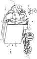
- the invention relates to a vehicle 1, in particular a commercial vehicle, equipped with a freight elevator 10, configured to move an object O from the ground S towards the interior of the vehicle 1 and vice versa.
- this object O is a construction machine, and more specifically a rammer.
- the freight elevator 10 comprises a fixed frame 2, a support platform 3, means 4 for guiding the platform 3 relative to the chassis 2, at least one elastic deformation device 5, at least one locking means 6 of the support platform 3 in the high position and at least one locking means 7 of the same platform in the low position.
- the frame 2 is fixed on the vehicle and consists of a plurality of profiles and metal sheets, assembled together so as to define a structure having substantially the general shape of a rectangular parallelepiped.
- the profiles form the uprights and the longitudinal members of the structure.
- this frame 2 is arranged perpendicular to the median longitudinal axis X-X 'of the vehicle 1 and opens on the passenger side of the vehicle 1.
- the frame 2 comprises two vertical rectangular sheets, arranged parallel to one another, which define two lateral flanks 20a, 20b.
- Another narrower rectangular sheet is folded at right angles, so as to have a horizontal part, which constitutes the bottom 21 of the frame, and a vertical part which extends downwards and which constitutes a rear wall 22.
- the bottom 21 interconnects the two lateral flanks 20a and 20b by their respective lower edges, except in the rear part of the frame 2.
- Two additional plates 23a and 23b are fixed in the extension of the lower rear edge of each of the two lateral flanks 20a and 20b. They are parallel to each other, vertical and are called "side walls". These side walls 23a and 23b delimit with the rear wall 22, a well 24, inside which is moved the platform 3.
- the two lateral flanks 20a, 20b are connected to their upper part by a sheet 25, which ensures the stiffening of the entire structure.
- the shape and dimensions of the frame 2 can be adapted differently depending on the nature and dimensions of the object O that it is desired to load in the vehicle 1.
- the chassis 2 has the role of allowing the attachment of the other elements 3 to 7.
- the support platform 3 is also made using several metal sheets, assembled together by appropriate means, such as screwing, bolting or welding.
- the platform 3 comprises a horizontal bottom 30 and a vertical rear wall 31, preferably of square or rectangular shape, and two side walls 32a, 32b.
- Each side wall 32a, 32b comprises a rectangular portion 320a, 320b, which extends between its upper front corner and the central portion of its upper edge, by a flange 321a, 321b of oblong shape, inclined upwards and forwards .
- the platform 3 also comprises a door 33, preferably a tilting door, pivoted rearwardly about an axis of rotation 34.
- This axis 34 extends to the lower part of the door and between the two lower rear angles of the two side walls 32a, 32b.
- the upper part of this door 33 has an inner bevel 330 which defines an inclined ramp, facilitating the introduction of the object O onto the bottom 30.
- the door 33 has locking means 35, which cooperate with the two side walls 32a and 32b, in order to maintain it in the vertical closed position, during the displacement of the support platform 3.
- the platform 3 with its bottom 30, its rear wall 31, its side walls 32a, 32b and its door 33, forms a cage which moves inside the well 24.
- one of the vertical walls of the platform 3 may have means for immobilizing the object O, (not shown), in order to prevent any inadvertent movement thereof during the movement of the vehicle 1.
- guide means 4 make it possible to guide the displacement of the platform 3 relative to the chassis 2 between a so-called “low” position and a so-called “high” position of said platform and vice versa.
- identical guiding means 4 are arranged on either side of both sides of the platform 3. Only one of them will be described here in more detail.
- the guiding means 4 comprises a slideway 41, within which a movable slide 42 is guided in translation.
- a slideway 41 within which a movable slide 42 is guided in translation.
- One of these elements is fixed to the frame 2 and the other to the support platform 3.
- the slide 41 is fixed on the outer face of the wing 321a while the slide 42 is fixed on the inner face of the side wall 23a.
- the slideway 41 and slider 42 are thus inclined at an angle ⁇ relative to the vertical, between 0 ° and 60 °, preferably of the order of 30 °, this inclination allowing the rammer to be progressively removed from the chassis of the vehicle during its downhill movement so that its overhanging rear part does not hit it.
- the slide 41, the slider 42 and the wings 321a, 321b could be oriented vertically.
- the displacement of the cage of the platform 3 relative to the frame 2 is carried out in an upward or downward movement, either vertical or close to the vertical according to the shape of the apparatus to be handled.
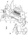
- the platform 3 When the platform 3 is in the low position, represented on the figures 1 and 3 , its bottom 30 is at ground level S or substantially at ground level S (that is to say at a short distance from it), so that an operator can load or unload the object O.
- the overhead door 33 can pivot further towards the ground to make up the difference in level between the ground S and the bottom 30 and facilitate the transfer of the object O on the bottom 30 from the ground S and vice versa.
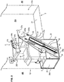
- the platform 3 When the platform 3 is in the high position, represented on the figure 2 it is at an altitude higher than that of the low position. It is then at a level that allows the movement of the vehicle. In this high position, the bottom 30 is at the same height as the floor of the vehicle 1, which can move the object O to the inside of the latter, or at a position slightly lower than the floor. In the latter case, the object O then remains in place on the bottom 30, without being able to be moved inside the vehicle.
- the slideway 41 and the slider 42 are preferably fixed respectively on the platform 3 and on the chassis 2, so that the slide is fully retracted into the slide, when the platform 3 is in the down position (see figure 3 ) and that the slide 42 is released to the maximum of the slide 41, when the platform 3 is in the up position, (see figure 2 ).
- these locking means comprise two hooks 60a, 60b, pivotally mounted respectively with respect to the lateral flanks 20a, 20b, these hooks, called “first hooks”, being arranged horizontally opposite each other.
- the hook 60a consists of a thin plate having three lobes arranged around a central orifice 61a.
- the hook 60a is pivotally mounted about an axis 270a integral with the side 20a of the frame and which extends through the orifice 61a.
- One of the lobes is an end 62a curved upwardly and rearwardly and adapted to cooperate with a locking pin 36a fixed on the outer face of the flange 321a.
- a second lobe located substantially opposite to the end 62a with respect to the orifice 61a constitutes a control end 63a, on which it is possible to act to pivot the hook 60a, around an integral axis 270a. a plate 27a, itself fixed on the inner face of the sidewall 20a.
- the hook 60a can thus pivot in a locking position (clockwise), in which it holds the finger 36a and conversely in an unlocking position (counterclockwise), in which it releases it.
- these locking means 6 are automatic locking means.
- the control end 63a is connected, on the one hand, to a return spring 64a, and on the other hand, in an articulated manner, to a actuating member 65a, here a rod, which acts in the opposite direction of the spring 64a.
- the other end of the return spring 64a is fixed on the plate 27a.
- a gripping bar 28 (see figures 2 and 3 ), to which the operator can hook, is mounted horizontally between the two sides 20a and 20b, perpendicular thereto, and at a short distance backwards relative to said first locking hooks 60a and 60b.
- An actuating handle 280 is pivotally mounted at both ends of this bar 28.
- the actuating handle 280 comprises a horizontal rod 281 at both ends of which are fixed two tabs 282a, 282b perpendicular. These tabs are pivotally mounted at their free end around the bar 28.
- the rods 65a, 65b are fixed respectively to these two tabs 282a, 282b, by an articulated connection.
- the third lobe of the hook 60a defines a third end 66a disposed between the two curved ends 62a and control 63a.
- a connecting rod or rod 67a is fixed at its two ends, in an articulated manner, on the one hand at the end 66a of the first hook 60a and on the other hand, at one end 73a of a second hook 70a which constitutes one locking means 7 of the platform 3 in the low position.
- This rod 67a provides the kinematic connection between the two hooks, and therefore their simultaneous movement.
- these locking means also comprise another second hook 70b identical to the hook 70a and whose component parts bear the same numerical references plus the letter "b".
- the second hook 70a is pierced with a hole 71a around which it is pivotally mounted about an axis 280a integral with a plate 28a, itself fixed on the inner face of the frame 2, more precisely the sidewall 20a.
- the hook 70a has two lobes extending substantially at right angles to one another, one defining an end 72a curved downwardly and forwards, and the other end 73a aforementioned control end.
- the end 72a is adapted to cooperate with the teeth of a rack 37a fixed on the outer face of the oblong wing 321a of the platform 3.
- This rack 37a extends parallel to the slideway 41.
- the hook 70a and more particularly its curved end 72a are close to the rack 37a.
- the return spring 64a via the rod 67a tends permanently to pivot the hook 70a in its locking position, in which its end 72a cooperates with one of the teeth of the rack 37a.
- the operator pulls on the rod 281 he also brings the hook 70a into its unlocked position.
- the elastic deformation device 5 comprises a fixed part mechanically linked to the frame 2 and an elastically deformable or elastically movable part, mechanically linked to the mobile platform 3.
- This device 5 is able to deform under the action of the force (weight) that the operator and / or object O exerts on the device 5 because of its mass and its position in the gravitational field.
- the operator increases his potential energy in the field of terrestrial gravitation.
- the device 5 is capable of accumulating this potential energy, provided by at least one operator mounted on the mobile platform 3 when it is in the up position and / or provided by the object O placed on this mobile platform during the downward movement of the platform 3 to the low position.
- this elastic deformation device 5 is then capable of restoring this potential energy substantially constant and with a controlled speed, said mobile platform 3 to ensure, in whole or in part accompanying an additional driving force, the upward movement thereof.
- gas cylinder 50 comprising a sealed body 51 containing a compressed gas and oil, a piston and a rod 52.
- the free end 510 of the body 51 is fixed to the frame 2, more precisely on the inside face of the side wall 23a of the well 24.
- the free end 520 of the rod 52 is, in turn, fixed to the platform 3 and, more precisely, on the outer face of the oblong portion 321a of the cage.
- a gas cylinder 50 on each side of the platform 3, more preferably two on each side, as shown in the figures, and this, for reasons of safety in order to prevent a possible mechanical failure of one of them.
- the gas spring 50 is advantageously a thrust spring, that is to say that its rest position is that in which the rod is out (see figure 2 ).
- the cylinder 50 contains advantageously comprises an internal damping device limiting its retraction speed.
- the gas cylinder 50 is set so that its resistant force in the downward vertical direction is equal to or slightly less than or slightly greater than the force created, on the slides, by the weight of the platform 3 and the object O.
- the elevator according to the invention is dedicated to the handling of a specific object O, for example here the rammer, this object has a known weight and the aforementioned adjustment is easy. We'll see later, in another embodiment, when the elevator is intended to move different objects, so different weights, some adjustments may be necessary.
- This complementary muscular force can be applied either directly by the operator who raises the platform 3, or with the aid of a complementary lifting device.
- the device 8 comprises two chains or transmission cables 80a, 80b, one end of which is fixed to the flange 321a, respectively 321b, of the platform 3 and the other to one of the branches 810a, respectively 810b of a control lever. 81 inverted U-shaped control.
- This control lever 81 is pivotally mounted, at its lower free ends, about axes 29a, respectively 29b, formed on integral plates of the frame 2.
- each transmission chain 80a, 80b meshes with a pinion, rotatably mounted on the plate 27a, 27b.
- a single pinion, referenced 82 is visible in the figures. This pinion is placed higher than the end of the wings 321a, 321b.
- springs 83a, 83b maintain the chains 80a, 80b in a state of permanent tension.
- the actuating handle 280 is advantageously supported by the control lever 81 in place of the bar 28.
- the rammer C is on the platform 3 in high position.
- the operator pulls on the two safety locks which block the sliding of the platform relative to the frame 2 (not described) and then actuates the actuating handle 280 so as to release the locking fingers 36a, 36b.
- the platform 3 then begins to descend under the weight of the rammer if the cylinders 5 exert a lower upward force than the vertical downward force of gravity.
- the operator exerts directly on the platform 3 and / or on the object O, that is to say a complementary muscular effort to bring them down, or rises beforehand on the gate 33 of the platform 3 to bring the additional weight missing.
- the descent movement of the platform 3 stops when the latter reaches either the ground level or the mechanical limit position of the lower position of the slide 42 relative to the slideway 41, or the limit of the stroke of the gas cylinders 50
- the locking hooks 70a, 70b then engage automatically in the racks 37a, 37b. Note that the height of the locking position in the lower position of the platform 3 is equal to or just greater than the stop position of this platform in contact with the ground or at the end of mechanical travel.
- the operator can then actuate the lock 35 of the door 33 and tilt it horizontally outwards.
- the platform 3 then begins its upward movement under the thrust of gas springs 50 and mastered under the effect of their internal dampers.
- the operator holds the handle 280 in the unlocked position of the hooks 70a, 70b approximately halfway, that is to say after the racks 37a, 37b are no longer in correspondence of the hooks 70a, 70b, so that to avoid their inadvertent re-engagement.
- the platform 3 is automatically locked under the action of the locking hooks 60a, 60b.
- the hooks 60a and 60b deviate automatically at the passage of the locking fingers 36a, 36b and then close again.
- the fingers 36a, 36b do not remain in abutment against the hooks 60a, 60b because, the platform 3 being empty, the gas springs 50 are held in abutment of their own mechanical end position (relaxed position).
- the platform 3 goes on the platform 3 and then actuates the handle 280 so as to unlock the upper locking means 60a, 60b, the platform 3 then drops under the weight of the operator.
- the weight of the operator is insufficient to lower the platform, it can take with it an additional charge or exercise a complementary downward muscle force or call a second operator who will also exert his weight on the platform.
- the gas springs 50 compress and accumulate the potential energy of the operator during the descent of the platform 3.
- the operator can then place the rammer C on the platform with the door open, close the door and unlock the locking means 7 of the platform in the low position.
- the gas springs 50 restore the energy they accumulated during the previous descent, which has the effect of causing the upward movement of the platform.
- the platform 3 then locks automatically in the up position.
- This variant differs from the previous one in that the platform, referenced 3 ', deploys from inside the vehicle to a horizontal position outside the vehicle 1.
- the platform 3 ' comprises a plate 300' pivotally mounted relative to two vertical uprights 420a, 420'b.
- the deployment of the plate 300 ' can be done by tilting about an axis 301' of a vertical position not exceeding the outer contours of the vehicle to a horizontal position overflowing the vehicle, as shown in the attached diagram, and thanks to opening / closing compasses 311'a, 311'b which connect the plate 300 'to the uprights 420a, 420b.
- the deployment can also be done by sliding in a horizontal plane from the inside of the vehicle to the outside, the goods can then remain on the platform when it is in position on or in the vehicle.
- the set of axes 301 ' is then replaced by a set of double rollers (not shown) linked by a support to the vertical uprights 420a and 420b and each sliding in a slide disposed on the outer lateral edges of the platform.
- the amounts 420a, 420b constitute the movable portion (slider) of at least one vertical or substantially vertical slide 410a, 410b of a displacement guide device 4 "of the platform 3 'relative to the frame 2.
- These slides 410a, 410b are formed on the inner faces (facing one another) of columns 211a, 211b, secured to the frame 2.
- Each movable slider 420a, 420b is mechanically connected to a first elastic end of a device with elastic deformation or its elastically movable part, here respectively at the free end of the rod 52a, 52b of a gas cylinder 5'a , 5'b. It is preferably gas cylinders called "traction", whose rod is returned to the body at rest. This connection is effected by a chain 53a, respectively 53b.
- the second ends of the elastic devices 5'a, 5'b ie the bodies 51a, 51b of the cylinders) are fixed to the frame 2 of the vehicle.
- the jacks 5'a, 5'b are arranged vertically or substantially vertically, parallel to the slides 410a, 410b and the slides 420a, 420b.
- Each chain 53a, 53b meshes respectively with a pinion 54a, 54b, rotatably mounted at the upper end of the fixed columns 211a, 211b.
- a downward movement of the rods 52a, 52b respectively causes upward movement of the slides 420a, 420b and vice versa.
- the locking device 6 'of the platform in the up position and the locking device 7' of the platform in the low position are quite similar to the locking devices 6 and 7 previously described and will be described more succinctly. These locking devices are provided on the two fixed columns 211a, 211b.
- the device 6 comprises a pivoting hook 60 'and the device 7', a pivot hook 70 '.
- An axis 61 ' is pivotally mounted in a horizontal bearing of the column 211a and rigidly connects the hook 60' to an actuating handle 280 'placed on the other side of the column 211a.
- the axis 71 'of each hook 70' consists of a torsion bar automatically realizing its return in the locked position.
- the end of the hook side torsion bar 70 'pivots in a bearing and its opposite end is fixed rigidly to the column 211a, respectively 211b.
- the hooks 60 ', 70' can cooperate with a locking pin 411 fixed on the uprights 420a, 420b of the platform 3 '. Both hooks 60 ', 70' are interconnected by a rod 67 'which synchronizes their locking or unlocking movements.
- a hollow tube 283 connects the pinions 54a, 54b of the two guide columns 211a, 211b to synchronize the vertical movements of the slides 420a and 420b.
- the operator can thus act indifferently on the handle 280 'right or left to control the unlocking high position or low position of the platform.
- the elastic deformation device 5'a, 5'b used is sized to be able to accumulate the potential energy of the gravitational field of at least one operator and / or the object during the descent of the platform 3 'of a high position locked vertically to a low position also locked vertically.
- the vertical thrust force of this elastic deformation device is dimensioned according to the weight of the platform, the weight of the object O to be mounted in the vehicle, as well as the weight of one or more operators.
- the direction of movement is determined by the resultant force of two opposing forces: the upward vertical thrust of the potential energy accumulator elastic device 5'a, 5'b on the one hand and the downward vertical thrust generated by the weight of the platform 3 'and the load consisting of at least one operator and / or the object O to get off the vehicle or to board the vehicle.
- the weight of the 3 'platform has been intentionally neglected to simplify the presentation.
- the upward vertical thrust of the potential energy storage elastic deformation device 5'a, 5'b is 1000N.
- the operator weighs 70 kg. He wants to load an object with a weight of 80 kg on or in the vehicle, he must first rotate the platform 3 'to outside and then down. To do this, he rides in or on the vehicle 1. By raising his body with ease thanks to an excellent natural energy efficiency, the operator increases his potential energy in the field of gravity.
- the elastic energy storage device 5'a, 5'b In a second step, it will restore this potential energy to the elastic energy storage device 5'a, 5'b, as follows: it is installed on the platform with one or more additional unit loads of a total of 20 kg, forming a total mass of 110 kg. The operator can also mount a second operator.
- the platform 3 In a third step, the platform 3 'rises under the action of the elastic device 5'a, 5'b whose thrust of 1000N is greater than the weight of 80 kg of the object.
- the assembly represents a mass of 120 kg whose gravitational downward force is greater than the upward thrust of 1000N of the elastic accumulation device 5'a, 5'b.
- the operator releases the locking device in the high position of the platform.
- the latter released vertically, descends damply to the ground.
- the 3 'platform automatically locks in the down position.
- the operator removes the object from the platform. It can then raise the latter free of any load, under the effect of the permanent thrust of the elastic device damped speed until its automatic locking in the high position, the thrust of the device being greater than the empty weight of the platform 3 .
- the operator can also climb on the platform which then brings it back to the floor of the vehicle.
- the operator can exert an upward muscular effort of 20 kg directly on the platform 3 'or on the object.
- the 1000 N of vertical thrust of the elastic device 5'a, 5'b will prove to be insufficient and the muscular effort too important. In this case, it is necessary to use a complementary lifting device.
- This device 8 comprises a step 84 slidably mounted on one of the columns, here the column 211b.
- the step 84 is integral with a plate 840 which slides in a slideway 2110b provided on the outer face of the column 211b.
- the upper end 8400 of the plate 840 is mechanically connected to the descending strand of the chain 53b, the ascending strand pulls the platform 3 'upwards, the pinion 54b placed at the top of the column 211b effecting a 360 ° return of the movement .
- the step 84 is foldable upwards.
- the operator After installing the object O on the platform 3 'in the down position, the operator rises again on or in the vehicle raising a second time its potential energy. It then brings the additional upward force of about 700 N by climbing on the step 84.
- the platform 3 'can then climb with its load of 150 kg whose gravitational force is lower than the total upward traction of 1700 N.
- Such a device comprises a movable valve which obstructs the piston opening of the cylinder, which blocks the latter in position because the fluid can not then move from one chamber to another.
- This valve is actuated by a lever or control cable from outside the cylinder via a rod which slides in the piston rod.
- the thrust force can for example be adapted by using means for subtracting or adding fluid into the enclosure of the cylinder.
- the elastic deformation device 5, 5'a, 5'b consists of several elementary elastic devices forming an assembly ensuring maximum thrust of the platform from bottom to top along its slide
- a simple mechanical device allows subtracting one or more ends of at least one elementary elastic device from its point of attachment to the movable part of the platform 3 ', so as to reduce the upward vertical thrust to the necessary value which is a function of the weight of the object to lift.
- the thrust of the elastic deformation device can be adjusted using a lever with variable arm length.
- the full thrust force of the elastic deformation device is exerted on the platform by means of a lever with variable arm length to reduce the transmitted force.
- This thrust reduction device of the elastic device allows the operator to ensure the descent of the platform when the object, which is placed therein, has a mass insufficient to overcome the full thrust of the elastic device.
Landscapes
- Engineering & Computer Science (AREA)
- Transportation (AREA)
- Mechanical Engineering (AREA)
- Forklifts And Lifting Vehicles (AREA)
- Auxiliary Methods And Devices For Loading And Unloading (AREA)
- Vehicle Step Arrangements And Article Storage (AREA)
Claims (13)
- Fahrzeug (1), insbesondere Nutzfahrzeug, das mit einem Lastenaufzug (10) ausgestattet ist, der so konfiguriert ist, dass er ein Objekt (O), wie zum Beispiel eine Baumaschine, vom Boden aus ins Innere des Fahrzeugs und umgekehrt versetzt, wobei dieser Lastenaufzug (10) Folgendes umfasst:- ein feststehendes Rahmenwerk (2), das fest mit dem Fahrzeug verbunden ist,- eine Trägerplattform (3, 3') für das Objekt (O), die gegenüber dem Rahmenwerk (2) mit einer Aufwärtsbewegung zwischen einer sogenannten "unteren" Position, in der sie sich auf Bodenebene oder deutlich auf Bodenebene befindet, damit das Laden oder Abladen des Objekts (O) ab oder auf den Boden durch einen Bediener möglich ist, und einer sogenannten "oberen" Position und umgekehrt in einer Abwärtsbewegung mobil ist,- zumindest ein Führungsmittel (4, 4") bei der Bewegung der Plattform (3, 3') gegenüber dem Rahmenwerk (2),- zumindest ein Sperrmittel (6, 6') der Plattform in der oberen Position,- zumindest ein Sperrmittel (7, 7') der Plattform in der unteren Position,- zumindest eine elastische Verformungsvorrichtung (5, 5'a, 5'b), von der ein feststehender Teil (51, 51a, 51b) mit dem Rahmenwerk (2) mechanisch verbunden ist, und von der ein elastisch verformbarer oder elastisch mobiler Teil (52, 52a, 52b) mechanisch mit der mobilen Plattform (3, 3') verbunden ist,wobei dieser Lastenaufzug (10) dadurch gekennzeichnet ist, dass das mobile Führungsmittel (4) eine Gleitschiene (41, 410a, 410b) und einen Schieber (42, 420a, 420b) umfasst, von denen die eine fest mit der mobilen Plattform (3, 3') verbunden ist und der andere fest mit dem Rahmenwerk (2) verbunden ist, um eine Translationsbewegung der Plattform gegenüber dem Rahmenwerk in einer senkrechten oder deutlich senkrechten Richtung zwischen der unteren und der oberen Position der Plattform (3, 3') zu erzielen,
und dadurch, dass die elastische Verformungsvorrichtung (5, 5'a, 5'b) so konfiguriert ist, dass sie:- während der Translationsbewegung der Plattform (3, 3') abwärts bis zu ihrer unteren Position die potenzielle Energie des Schwerefelds sammelt, die zuvor von zumindest einem auf der mobilen Plattform (3, 3') stehenden Bediener bereitgestellt wird, wenn sie in oberer Position ist, oder die zuvor von zumindest einem auf der mobilen Plattform (3, 3') stehenden Bediener und von dem auf die mobile Plattform gestellten Objekt (O) bereitgestellt wird, wenn diese in oberer Position ist,- die Abstiegsgeschwindigkeit der mobilen Plattform steuert,- diese gesammelte potenzielle Energie deutlich konstant und mit einer gesteuerten Geschwindigkeit an die mobile Plattform (3, 3') zurückführt, um deren Aufstiegsgeschwindigkeit in ihrer Gesamtheit sicherzustellen. - Fahrzeug nach Anspruch 1, dadurch gekennzeichnet, dass die elastische Verformungsvorrichtung (5, 5'a, 5'b) eine Gasdruckfeder ist, deren Schub deutlich konstant ist, deren Geschwindigkeit gesteuert wird, und die einen Körper (51, 51a, 51b) und eine bewegliche Stange (52, 52a, 52b) umfasst, von denen einer mit der Plattform (3, 3') und die andere fest mit dem Rahmenwerk (2) verbunden ist.
- Fahrzeug nach Anspruch 2, dadurch gekennzeichnet, dass die Gasdruckfeder so konfiguriert ist, dass sie eine aufwärts gerichtete Kraft aufweist, die größer als das Gewicht der mobilen Plattform und des zu bewegenden Objekts (O) ist, um den autonomen Aufstieg der Plattform (3, 3') mit dem Objekt vollständig zu gewährleisten.
- Fahrzeug nach Anspruch 2 oder 3, dadurch gekennzeichnet, dass die Gasdruckfeder parallel zur Gleitschiene (41, 410a, 410b) und dem Schieber (42, 420a, 420b) verläuft.
- Fahrzeug nach einem der Ansprüche 2 bis 4, dadurch gekennzeichnet, dass die Gasdruckfeder eine Schubfeder ist.
- Fahrzeug nach einem der vorstehenden Ansprüche, dadurch gekennzeichnet, dass die Sperrmittel der Plattform in der oberen Position und/oder die Sperrmittel der Plattform (3, 3') in der unteren Position ein bewegliches Ventil zum Blockieren der Kolbenöffnung eines Zylinders umfassen, das verhindert, dass das im Zylinder vorhandene Fluid von einer Kammer zur anderen davon übergeht.
- Fahrzeug nach einem der vorstehenden Ansprüche, dadurch gekennzeichnet, dass das Rahmenwerk (2) mit einer starren Stange (28) ausgerüstet ist, an der sich der Bediener festhalten kann, um seinen Aufstieg auf der mobilen Plattform (3) zu vereinfachen und zu sichern, wobei diese starre Stange (28) mit zumindest einem Betätigungsgriff (280) für die Sperrmittel (6) der Plattform in der oberen Position und/oder Sperrmittel (7) der Plattform in der unteren Position ausgestattet ist.
- Fahrzeug nach einem der vorstehenden Ansprüche, dadurch gekennzeichnet, dass die Sperrmittel (6) der Plattform in der oberen Position einen Haken (60a, 60b, 60'), den sogenannten "ersten Haken", umfassen, der um eine am Rahmenwerk (2) befestigte Achse (270a, 270b, 61') schwenkbar gelagert ist, und dessen gekrümmtes Ende (62a, 62b) so konfiguriert ist, dass es mit einem an der mobilen Plattform (3) befestigten Sperrstift (36a, 36b, 411) zusammenwirkt.
- Fahrzeug nach Anspruch 8, dadurch gekennzeichnet, dass die Sperrmittel (6) der Plattform in der oberen Position automatische Sperrmittel sind, dadurch, dass der erste Haken (60a, 60b) mit einer Rückstellfeder (64a, 64b) ausgerüstet ist, die ständig danach strebt, sie in die Sperrposition zurückzuführen, und dadurch, dass die Sperrmittel (6) ein Betätigungselement (280, 65a, 65b) umfassen, mit dem der erste Haken (60a, 60b) gegen die Kraft der Rückstellfeder (64a, 64b) geschwenkt werden kann, um ihn in eine sperrfreie Position zu bringen, in der er den Sperrstift (36a, 36b) freigibt.
- Fahrzeug nach einem der vorstehenden Ansprüche, dadurch gekennzeichnet, dass die Sperrmittel (7) der Plattform in der unteren Position einen Haken, den sogenannten "zweiten Haken" (70a, 70b), umfassen, der um eine am Fahrgestell (2) befestigte Achse (28a) schwenkbar gelagert ist, und dessen gekrümmtes Ende (72a, 72b) so konfiguriert ist, dass es mit einer fest mit der Plattform (3) verbundenen Zahnstange (37a, 37b) zusammenwirkt.
- Fahrzeug nach Anspruch 8 oder 9, dadurch gekennzeichnet, dass die Sperrmittel (7) der Plattform in der unteren Position einen Haken (70a, 70b), den sogenannten "zweiten Haken", umfassen, der um eine am Rahmenwerk (2) befestigte Achse (28a) schwenkbar gelagert ist, und dessen gekrümmtes Ende (72a, 72b) so konfiguriert ist, dass es mit einer Zahnstange (37a, 37b) zusammenwirkt, die fest mit der Plattform (3) verbunden ist, und dass der erste Haken (60a, 60b, 60') und der zweite Haken (70a, 70b, 70') kinematisch verbunden sind, so dass ihre Anordnungen in gesperrter oder offener Position gleichzeitig eintreten.
- Fahrzeug nach einem der vorstehenden Ansprüche, dadurch gekennzeichnet, dass die Plattform (3) mit zumindest einem Dämpfer ausgestattet ist, mit dem ihre Auf- und Abstiegsgeschwindigkeit gesteuert werden kann.
- Fahrzeug nach einem der vorstehenden Ansprüche, dadurch gekennzeichnet, dass es eine Verstelleinrichtung für die von der/den elastischen Verformungsvorrichtung(en) (5, 5'a, 5'b) ausgeübten Schubkraft umfasst.
Applications Claiming Priority (1)
| Application Number | Priority Date | Filing Date | Title |
|---|---|---|---|
| FR1460880A FR3028225B1 (fr) | 2014-11-12 | 2014-11-12 | Vehicule equipe d'un monte-charge |
Publications (2)
| Publication Number | Publication Date |
|---|---|
| EP3020601A1 EP3020601A1 (de) | 2016-05-18 |
| EP3020601B1 true EP3020601B1 (de) | 2019-05-15 |
Family
ID=52824322
Family Applications (1)
| Application Number | Title | Priority Date | Filing Date |
|---|---|---|---|
| EP15194358.6A Active EP3020601B1 (de) | 2014-11-12 | 2015-11-12 | Fahrzeug, das mit einem lastenaufzug ausgestattet ist |
Country Status (2)
| Country | Link |
|---|---|
| EP (1) | EP3020601B1 (de) |
| FR (1) | FR3028225B1 (de) |
Families Citing this family (2)
| Publication number | Priority date | Publication date | Assignee | Title |
|---|---|---|---|---|
| CN107117106B (zh) * | 2017-04-19 | 2023-03-03 | 常熟华东汽车有限公司 | 车辆的与侧防护栏组合的抽出式登车平台 |
| US20220176861A1 (en) * | 2020-12-04 | 2022-06-09 | Cornerstone Manufacturing Company LLC | Lifting device mounted to a vehicle |
Family Cites Families (5)
| Publication number | Priority date | Publication date | Assignee | Title |
|---|---|---|---|---|
| FR1458603A (fr) * | 1965-09-29 | 1966-03-04 | Dispositif pour le chargement et le déchargement de véhicules | |
| GB2067502A (en) * | 1980-01-15 | 1981-07-30 | Ratcliff Tail Lifts Ltd | Load lifting and lowering apparatus |
| FR2821031A1 (fr) * | 2001-02-19 | 2002-08-23 | Gerard Grosse | Vehicule de transport de marchandises a plateforme elevatrice |
| AT12673U1 (de) * | 2011-06-30 | 2012-09-15 | Rosenbauer Int Ag | Ausschwenkvorrichtung für die entnahme von gegenständen aus einem fahrzeug |
| WO2014138797A1 (en) * | 2013-03-15 | 2014-09-18 | Shane Robert Miles | Elevating storage apparatus |
-
2014
- 2014-11-12 FR FR1460880A patent/FR3028225B1/fr active Active
-
2015
- 2015-11-12 EP EP15194358.6A patent/EP3020601B1/de active Active
Non-Patent Citations (1)
| Title |
|---|
| None * |
Also Published As
| Publication number | Publication date |
|---|---|
| FR3028225A1 (fr) | 2016-05-13 |
| FR3028225B1 (fr) | 2018-02-16 |
| EP3020601A1 (de) | 2016-05-18 |
Similar Documents
| Publication | Publication Date | Title |
|---|---|---|
| EP0029384A1 (de) | Gabelstapler mit gleichzeitiger Steuerung von verstellbar angetriebenen Roll- und Greifflächen | |
| WO2006120347A1 (fr) | Etabli elevateur | |
| EP3020601B1 (de) | Fahrzeug, das mit einem lastenaufzug ausgestattet ist | |
| EP3051049B1 (de) | Schalung oder gerüst bestehend aus eine automatische öffnungs-/schliessvorrichtung einer klappe | |
| EP2806097B1 (de) | Trittstufe mit einziehbaren Rädern, und mit einem handbedienten Schwenkvorderrad | |
| EP1953112B1 (de) | Hubgerät | |
| EP3933157B1 (de) | Türflügel für arbeitsbühne zum arbeiten in der höhe und arbeitsbühne, die einen solchen türflügel umfasst | |
| EP0002865B1 (de) | Vorrichtung zur beliebigen Umwandlung eines Saales | |
| FR3040410B1 (fr) | Plancher mobile pour piscine et piscine equipee d'un tel plancher | |
| EP3333341B1 (de) | Vorrichtung für das handling einer verschalungsplatte | |
| EP3400622A1 (de) | Stationärer schutzraum zur aufbewahrung von mindestens einer stromspeichereinheit | |
| EP0612899A1 (de) | Gerüstboden und Montageverfahren für Gerüste mit diesem Boden | |
| WO2018150107A1 (fr) | Dispositif pour conditionner les mouvements d'un plateau de couchage horizontal escamotable au plafond à l'ouverture de ses pieds ou jambages | |
| EP3940189B1 (de) | Vorrichtung zum arbeiten in der höhe mit gelenkgeländer und automatischer tür | |
| FR2904596A1 (fr) | Vehicule automobile a cabine amovible | |
| FR3020351A1 (fr) | Dispositif de chargement en dechets d'une benne de dechetterie depuis une plateforme | |
| EP3898482B1 (de) | Absturzsicherung für motorgetriebene zahnstangenaufzüge | |
| EP1420980A1 (de) | Verfahren zur steuerung der seitengeländer eines fahrzeugaufzugs und vorrichtung dafür | |
| FR3121166A1 (fr) | Dispositif d’accès en hauteur tel que plateforme avec stabilisateurs et pieds télescopiques | |
| FR2474576A1 (fr) | Dispositif de protection contre les agressions | |
| FR2497161A1 (fr) | Vehicule utilitaire a carrosserie interchangeable verrouillable coulissante | |
| EP1630121B1 (de) | Greifrahmen | |
| WO1996027729A2 (fr) | Ensemble constitue, nacelle et plate-forme de travail en hauteur avec acces sur escamobile et le convertible esca 2000, echelle automobile a propulsion manuelle et entrainement multidirectionnel | |
| BE894560Q (fr) | Porte de secours pour vehicules, ferroviaires | |
| EP4227478A1 (de) | Verriegelbare stütze durch automatisch betätigbare system |
Legal Events
| Date | Code | Title | Description |
|---|---|---|---|
| PUAI | Public reference made under article 153(3) epc to a published international application that has entered the european phase |
Free format text: ORIGINAL CODE: 0009012 |
|
| AK | Designated contracting states |
Kind code of ref document: A1 Designated state(s): AL AT BE BG CH CY CZ DE DK EE ES FI FR GB GR HR HU IE IS IT LI LT LU LV MC MK MT NL NO PL PT RO RS SE SI SK SM TR |
|
| AX | Request for extension of the european patent |
Extension state: BA ME |
|
| STAA | Information on the status of an ep patent application or granted ep patent |
Free format text: STATUS: REQUEST FOR EXAMINATION WAS MADE |
|
| 17P | Request for examination filed |
Effective date: 20161117 |
|
| RBV | Designated contracting states (corrected) |
Designated state(s): AL AT BE BG CH CY CZ DE DK EE ES FI FR GB GR HR HU IE IS IT LI LT LU LV MC MK MT NL NO PL PT RO RS SE SI SK SM TR |
|
| GRAP | Despatch of communication of intention to grant a patent |
Free format text: ORIGINAL CODE: EPIDOSNIGR1 |
|
| STAA | Information on the status of an ep patent application or granted ep patent |
Free format text: STATUS: GRANT OF PATENT IS INTENDED |
|
| INTG | Intention to grant announced |
Effective date: 20181205 |
|
| GRAS | Grant fee paid |
Free format text: ORIGINAL CODE: EPIDOSNIGR3 |
|
| GRAA | (expected) grant |
Free format text: ORIGINAL CODE: 0009210 |
|
| STAA | Information on the status of an ep patent application or granted ep patent |
Free format text: STATUS: THE PATENT HAS BEEN GRANTED |
|
| AK | Designated contracting states |
Kind code of ref document: B1 Designated state(s): AL AT BE BG CH CY CZ DE DK EE ES FI FR GB GR HR HU IE IS IT LI LT LU LV MC MK MT NL NO PL PT RO RS SE SI SK SM TR |
|
| REG | Reference to a national code |
Ref country code: CH Ref legal event code: EP |
|
| REG | Reference to a national code |
Ref country code: DE Ref legal event code: R096 Ref document number: 602015030273 Country of ref document: DE |
|
| REG | Reference to a national code |
Ref country code: IE Ref legal event code: FG4D Free format text: LANGUAGE OF EP DOCUMENT: FRENCH |
|
| REG | Reference to a national code |
Ref country code: NL Ref legal event code: MP Effective date: 20190515 |
|
| REG | Reference to a national code |
Ref country code: LT Ref legal event code: MG4D |
|
| PG25 | Lapsed in a contracting state [announced via postgrant information from national office to epo] |
Ref country code: ES Free format text: LAPSE BECAUSE OF FAILURE TO SUBMIT A TRANSLATION OF THE DESCRIPTION OR TO PAY THE FEE WITHIN THE PRESCRIBED TIME-LIMIT Effective date: 20190515 Ref country code: SE Free format text: LAPSE BECAUSE OF FAILURE TO SUBMIT A TRANSLATION OF THE DESCRIPTION OR TO PAY THE FEE WITHIN THE PRESCRIBED TIME-LIMIT Effective date: 20190515 Ref country code: AL Free format text: LAPSE BECAUSE OF FAILURE TO SUBMIT A TRANSLATION OF THE DESCRIPTION OR TO PAY THE FEE WITHIN THE PRESCRIBED TIME-LIMIT Effective date: 20190515 Ref country code: PT Free format text: LAPSE BECAUSE OF FAILURE TO SUBMIT A TRANSLATION OF THE DESCRIPTION OR TO PAY THE FEE WITHIN THE PRESCRIBED TIME-LIMIT Effective date: 20190915 Ref country code: FI Free format text: LAPSE BECAUSE OF FAILURE TO SUBMIT A TRANSLATION OF THE DESCRIPTION OR TO PAY THE FEE WITHIN THE PRESCRIBED TIME-LIMIT Effective date: 20190515 Ref country code: NO Free format text: LAPSE BECAUSE OF FAILURE TO SUBMIT A TRANSLATION OF THE DESCRIPTION OR TO PAY THE FEE WITHIN THE PRESCRIBED TIME-LIMIT Effective date: 20190815 Ref country code: LT Free format text: LAPSE BECAUSE OF FAILURE TO SUBMIT A TRANSLATION OF THE DESCRIPTION OR TO PAY THE FEE WITHIN THE PRESCRIBED TIME-LIMIT Effective date: 20190515 Ref country code: NL Free format text: LAPSE BECAUSE OF FAILURE TO SUBMIT A TRANSLATION OF THE DESCRIPTION OR TO PAY THE FEE WITHIN THE PRESCRIBED TIME-LIMIT Effective date: 20190515 Ref country code: HR Free format text: LAPSE BECAUSE OF FAILURE TO SUBMIT A TRANSLATION OF THE DESCRIPTION OR TO PAY THE FEE WITHIN THE PRESCRIBED TIME-LIMIT Effective date: 20190515 |
|
| PG25 | Lapsed in a contracting state [announced via postgrant information from national office to epo] |
Ref country code: RS Free format text: LAPSE BECAUSE OF FAILURE TO SUBMIT A TRANSLATION OF THE DESCRIPTION OR TO PAY THE FEE WITHIN THE PRESCRIBED TIME-LIMIT Effective date: 20190515 Ref country code: BG Free format text: LAPSE BECAUSE OF FAILURE TO SUBMIT A TRANSLATION OF THE DESCRIPTION OR TO PAY THE FEE WITHIN THE PRESCRIBED TIME-LIMIT Effective date: 20190815 Ref country code: GR Free format text: LAPSE BECAUSE OF FAILURE TO SUBMIT A TRANSLATION OF THE DESCRIPTION OR TO PAY THE FEE WITHIN THE PRESCRIBED TIME-LIMIT Effective date: 20190816 Ref country code: LV Free format text: LAPSE BECAUSE OF FAILURE TO SUBMIT A TRANSLATION OF THE DESCRIPTION OR TO PAY THE FEE WITHIN THE PRESCRIBED TIME-LIMIT Effective date: 20190515 |
|
| REG | Reference to a national code |
Ref country code: AT Ref legal event code: MK05 Ref document number: 1133028 Country of ref document: AT Kind code of ref document: T Effective date: 20190515 |
|
| PG25 | Lapsed in a contracting state [announced via postgrant information from national office to epo] |
Ref country code: DK Free format text: LAPSE BECAUSE OF FAILURE TO SUBMIT A TRANSLATION OF THE DESCRIPTION OR TO PAY THE FEE WITHIN THE PRESCRIBED TIME-LIMIT Effective date: 20190515 Ref country code: EE Free format text: LAPSE BECAUSE OF FAILURE TO SUBMIT A TRANSLATION OF THE DESCRIPTION OR TO PAY THE FEE WITHIN THE PRESCRIBED TIME-LIMIT Effective date: 20190515 Ref country code: AT Free format text: LAPSE BECAUSE OF FAILURE TO SUBMIT A TRANSLATION OF THE DESCRIPTION OR TO PAY THE FEE WITHIN THE PRESCRIBED TIME-LIMIT Effective date: 20190515 Ref country code: SK Free format text: LAPSE BECAUSE OF FAILURE TO SUBMIT A TRANSLATION OF THE DESCRIPTION OR TO PAY THE FEE WITHIN THE PRESCRIBED TIME-LIMIT Effective date: 20190515 Ref country code: RO Free format text: LAPSE BECAUSE OF FAILURE TO SUBMIT A TRANSLATION OF THE DESCRIPTION OR TO PAY THE FEE WITHIN THE PRESCRIBED TIME-LIMIT Effective date: 20190515 Ref country code: CZ Free format text: LAPSE BECAUSE OF FAILURE TO SUBMIT A TRANSLATION OF THE DESCRIPTION OR TO PAY THE FEE WITHIN THE PRESCRIBED TIME-LIMIT Effective date: 20190515 |
|
| REG | Reference to a national code |
Ref country code: DE Ref legal event code: R097 Ref document number: 602015030273 Country of ref document: DE |
|
| PG25 | Lapsed in a contracting state [announced via postgrant information from national office to epo] |
Ref country code: SM Free format text: LAPSE BECAUSE OF FAILURE TO SUBMIT A TRANSLATION OF THE DESCRIPTION OR TO PAY THE FEE WITHIN THE PRESCRIBED TIME-LIMIT Effective date: 20190515 Ref country code: IT Free format text: LAPSE BECAUSE OF FAILURE TO SUBMIT A TRANSLATION OF THE DESCRIPTION OR TO PAY THE FEE WITHIN THE PRESCRIBED TIME-LIMIT Effective date: 20190515 |
|
| PLBE | No opposition filed within time limit |
Free format text: ORIGINAL CODE: 0009261 |
|
| STAA | Information on the status of an ep patent application or granted ep patent |
Free format text: STATUS: NO OPPOSITION FILED WITHIN TIME LIMIT |
|
| PG25 | Lapsed in a contracting state [announced via postgrant information from national office to epo] |
Ref country code: TR Free format text: LAPSE BECAUSE OF FAILURE TO SUBMIT A TRANSLATION OF THE DESCRIPTION OR TO PAY THE FEE WITHIN THE PRESCRIBED TIME-LIMIT Effective date: 20190515 |
|
| 26N | No opposition filed |
Effective date: 20200218 |
|
| PG25 | Lapsed in a contracting state [announced via postgrant information from national office to epo] |
Ref country code: PL Free format text: LAPSE BECAUSE OF FAILURE TO SUBMIT A TRANSLATION OF THE DESCRIPTION OR TO PAY THE FEE WITHIN THE PRESCRIBED TIME-LIMIT Effective date: 20190515 |
|
| PG25 | Lapsed in a contracting state [announced via postgrant information from national office to epo] |
Ref country code: SI Free format text: LAPSE BECAUSE OF FAILURE TO SUBMIT A TRANSLATION OF THE DESCRIPTION OR TO PAY THE FEE WITHIN THE PRESCRIBED TIME-LIMIT Effective date: 20190515 |
|
| REG | Reference to a national code |
Ref country code: CH Ref legal event code: PL |
|
| PG25 | Lapsed in a contracting state [announced via postgrant information from national office to epo] |
Ref country code: LU Free format text: LAPSE BECAUSE OF NON-PAYMENT OF DUE FEES Effective date: 20191112 Ref country code: CH Free format text: LAPSE BECAUSE OF NON-PAYMENT OF DUE FEES Effective date: 20191130 Ref country code: LI Free format text: LAPSE BECAUSE OF NON-PAYMENT OF DUE FEES Effective date: 20191130 Ref country code: MC Free format text: LAPSE BECAUSE OF FAILURE TO SUBMIT A TRANSLATION OF THE DESCRIPTION OR TO PAY THE FEE WITHIN THE PRESCRIBED TIME-LIMIT Effective date: 20190515 |
|
| GBPC | Gb: european patent ceased through non-payment of renewal fee |
Effective date: 20191112 |
|
| PG25 | Lapsed in a contracting state [announced via postgrant information from national office to epo] |
Ref country code: IE Free format text: LAPSE BECAUSE OF NON-PAYMENT OF DUE FEES Effective date: 20191112 Ref country code: GB Free format text: LAPSE BECAUSE OF NON-PAYMENT OF DUE FEES Effective date: 20191112 |
|
| PG25 | Lapsed in a contracting state [announced via postgrant information from national office to epo] |
Ref country code: CY Free format text: LAPSE BECAUSE OF FAILURE TO SUBMIT A TRANSLATION OF THE DESCRIPTION OR TO PAY THE FEE WITHIN THE PRESCRIBED TIME-LIMIT Effective date: 20190515 |
|
| PG25 | Lapsed in a contracting state [announced via postgrant information from national office to epo] |
Ref country code: IS Free format text: LAPSE BECAUSE OF FAILURE TO SUBMIT A TRANSLATION OF THE DESCRIPTION OR TO PAY THE FEE WITHIN THE PRESCRIBED TIME-LIMIT Effective date: 20190915 |
|
| PG25 | Lapsed in a contracting state [announced via postgrant information from national office to epo] |
Ref country code: MT Free format text: LAPSE BECAUSE OF FAILURE TO SUBMIT A TRANSLATION OF THE DESCRIPTION OR TO PAY THE FEE WITHIN THE PRESCRIBED TIME-LIMIT Effective date: 20190515 Ref country code: HU Free format text: LAPSE BECAUSE OF FAILURE TO SUBMIT A TRANSLATION OF THE DESCRIPTION OR TO PAY THE FEE WITHIN THE PRESCRIBED TIME-LIMIT; INVALID AB INITIO Effective date: 20151112 |
|
| PG25 | Lapsed in a contracting state [announced via postgrant information from national office to epo] |
Ref country code: MK Free format text: LAPSE BECAUSE OF FAILURE TO SUBMIT A TRANSLATION OF THE DESCRIPTION OR TO PAY THE FEE WITHIN THE PRESCRIBED TIME-LIMIT Effective date: 20190515 |
|
| P01 | Opt-out of the competence of the unified patent court (upc) registered |
Effective date: 20230530 |
|
| PGFP | Annual fee paid to national office [announced via postgrant information from national office to epo] |
Ref country code: FR Payment date: 20231012 Year of fee payment: 9 Ref country code: DE Payment date: 20231107 Year of fee payment: 9 |
|
| PGFP | Annual fee paid to national office [announced via postgrant information from national office to epo] |
Ref country code: BE Payment date: 20231113 Year of fee payment: 9 |