EP3020601B1 - Vehicle provided with a goods lift - Google Patents
Vehicle provided with a goods lift Download PDFInfo
- Publication number
- EP3020601B1 EP3020601B1 EP15194358.6A EP15194358A EP3020601B1 EP 3020601 B1 EP3020601 B1 EP 3020601B1 EP 15194358 A EP15194358 A EP 15194358A EP 3020601 B1 EP3020601 B1 EP 3020601B1
- Authority
- EP
- European Patent Office
- Prior art keywords
- platform
- locking
- hook
- frame
- vehicle according
- Prior art date
- Legal status (The legal status is an assumption and is not a legal conclusion. Google has not performed a legal analysis and makes no representation as to the accuracy of the status listed.)
- Active
Links
- 238000005381 potential energy Methods 0.000 claims description 18
- 238000010276 construction Methods 0.000 claims description 4
- 239000012530 fluid Substances 0.000 claims description 4
- 230000009194 climbing Effects 0.000 claims description 3
- 230000005484 gravity Effects 0.000 claims description 3
- 230000005489 elastic deformation Effects 0.000 description 15
- 230000000694 effects Effects 0.000 description 10
- 230000000295 complement effect Effects 0.000 description 9
- 230000003387 muscular Effects 0.000 description 9
- 238000006073 displacement reaction Methods 0.000 description 6
- 210000003205 muscle Anatomy 0.000 description 5
- 238000012550 audit Methods 0.000 description 4
- 230000036961 partial effect Effects 0.000 description 3
- 208000031968 Cadaver Diseases 0.000 description 2
- 230000001174 ascending effect Effects 0.000 description 2
- 230000005540 biological transmission Effects 0.000 description 2
- 238000012423 maintenance Methods 0.000 description 2
- 239000000463 material Substances 0.000 description 2
- 239000002184 metal Substances 0.000 description 2
- 238000005303 weighing Methods 0.000 description 2
- 208000028571 Occupational disease Diseases 0.000 description 1
- 241000287107 Passer Species 0.000 description 1
- 238000009825 accumulation Methods 0.000 description 1
- 230000006378 damage Effects 0.000 description 1
- 238000013016 damping Methods 0.000 description 1
- 238000010586 diagram Methods 0.000 description 1
- 238000004146 energy storage Methods 0.000 description 1
- 230000003100 immobilizing effect Effects 0.000 description 1
- 238000007689 inspection Methods 0.000 description 1
- 230000000670 limiting effect Effects 0.000 description 1
- 230000001105 regulatory effect Effects 0.000 description 1
- 230000003014 reinforcing effect Effects 0.000 description 1
- 230000000717 retained effect Effects 0.000 description 1
- 230000002441 reversible effect Effects 0.000 description 1
- 238000003466 welding Methods 0.000 description 1
Images


Classifications
-
- B—PERFORMING OPERATIONS; TRANSPORTING
- B60—VEHICLES IN GENERAL
- B60P—VEHICLES ADAPTED FOR LOAD TRANSPORTATION OR TO TRANSPORT, TO CARRY, OR TO COMPRISE SPECIAL LOADS OR OBJECTS
- B60P1/00—Vehicles predominantly for transporting loads and modified to facilitate loading, consolidating the load, or unloading
- B60P1/44—Vehicles predominantly for transporting loads and modified to facilitate loading, consolidating the load, or unloading having a loading platform thereon raising the load to the level of the load-transporting element
- B60P1/4414—Vehicles predominantly for transporting loads and modified to facilitate loading, consolidating the load, or unloading having a loading platform thereon raising the load to the level of the load-transporting element and keeping the loading platform parallel to the ground when raising the load
- B60P1/4421—Vehicles predominantly for transporting loads and modified to facilitate loading, consolidating the load, or unloading having a loading platform thereon raising the load to the level of the load-transporting element and keeping the loading platform parallel to the ground when raising the load the loading platform being carried in at least one vertical guide
-
- B—PERFORMING OPERATIONS; TRANSPORTING
- B60—VEHICLES IN GENERAL
- B60P—VEHICLES ADAPTED FOR LOAD TRANSPORTATION OR TO TRANSPORT, TO CARRY, OR TO COMPRISE SPECIAL LOADS OR OBJECTS
- B60P1/00—Vehicles predominantly for transporting loads and modified to facilitate loading, consolidating the load, or unloading
- B60P1/44—Vehicles predominantly for transporting loads and modified to facilitate loading, consolidating the load, or unloading having a loading platform thereon raising the load to the level of the load-transporting element
- B60P1/4414—Vehicles predominantly for transporting loads and modified to facilitate loading, consolidating the load, or unloading having a loading platform thereon raising the load to the level of the load-transporting element and keeping the loading platform parallel to the ground when raising the load
- B60P1/4442—Vehicles predominantly for transporting loads and modified to facilitate loading, consolidating the load, or unloading having a loading platform thereon raising the load to the level of the load-transporting element and keeping the loading platform parallel to the ground when raising the load the raising device, when not in use, being stored inside the load-transporting compartment
-
- B—PERFORMING OPERATIONS; TRANSPORTING
- B60—VEHICLES IN GENERAL
- B60P—VEHICLES ADAPTED FOR LOAD TRANSPORTATION OR TO TRANSPORT, TO CARRY, OR TO COMPRISE SPECIAL LOADS OR OBJECTS
- B60P1/00—Vehicles predominantly for transporting loads and modified to facilitate loading, consolidating the load, or unloading
- B60P1/44—Vehicles predominantly for transporting loads and modified to facilitate loading, consolidating the load, or unloading having a loading platform thereon raising the load to the level of the load-transporting element
- B60P1/4471—General means for controlling movements of the loading platform, e.g. hydraulic systems
- B60P1/4478—Safety stops, switches
Definitions
- the invention lies in the field of handling and lifting objects.
- the present invention relates to a vehicle, in particular a commercial vehicle, equipped with a freight elevator for loading and unloading heavy objects in / on and out of this vehicle.
- Object means any type of goods, materials, supplies, miscellaneous materials, machinery, tools or mobile devices.
- a particular application of the invention shown in the drawings relates to the handling of a construction machine, such as a rammer. Without limitation, it could also be an example of a vibrating plate, a pump, a hydraulic power unit or generator, a household appliance, a mobile public toilet cabin or of a concrete object.
- a device actuated by human force such as for example a pulley, a hoist or a manual hydraulic system, although it has the advantage of reducing the instantaneous muscular power required for lifting, also has the disadvantage of lengthening important the duration of the handling operation.
- This elevator includes an arm pivotally mounted at its lower end relative to a frame secured to the vehicle and a load support platform mounted articulated to the upper end of the pivoting arm.
- An actuator such as a gas cylinder, connects the lower end of the pivoting arm to the frame.
- the operator by means of a handle on the platform, can manually rotate the swivel arm, so as to move it from a "storage” position in which its upper end is slightly tilted towards the vehicle interior and the platform is in the vehicle, to a so-called “high point” position in which it is vertical and finally to an "unloading" position in which its upper end is tilted towards the outside of the vehicle and the platform is on the ground.
- the gas cylinder elongates and accumulates energy that it can restore during the reverse movement.
- This elevator device has many disadvantages listed below.
- the muscular effort is necessarily simultaneous with the movement of movement of the platform and the lifting force varies significantly during the race of the platform which must pass through a high point.
- the muscles of the operator are therefore highly stressed, especially during the descent of the platform, or the weight of the object to be unloaded must be limited.
- An object of the invention is to overcome the aforementioned drawbacks.
- the invention therefore aims to propose a vehicle equipped with a device that allows an operator to lift or lower objects between the ground and the vehicle, effortlessly, quickly, safely and without input of energy exterior.
- the invention also aims to provide a device for moving the object that is simple, robust and requires little maintenance.
- This device has the advantage of using the fact that a human being can accumulate potential energy with a particularly high efficiency through natural movements of his body, such as mounting on a platform or a vehicle floor which corresponds substantially to climbing one or more steps.
- This advantage is used to then accumulate and restore this potential energy using a suitable device and thus lift an object with less effort for the operator.
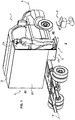
- the invention relates to a vehicle 1, in particular a commercial vehicle, equipped with a freight elevator 10, configured to move an object O from the ground S towards the interior of the vehicle 1 and vice versa.
- this object O is a construction machine, and more specifically a rammer.
- the freight elevator 10 comprises a fixed frame 2, a support platform 3, means 4 for guiding the platform 3 relative to the chassis 2, at least one elastic deformation device 5, at least one locking means 6 of the support platform 3 in the high position and at least one locking means 7 of the same platform in the low position.
- the frame 2 is fixed on the vehicle and consists of a plurality of profiles and metal sheets, assembled together so as to define a structure having substantially the general shape of a rectangular parallelepiped.
- the profiles form the uprights and the longitudinal members of the structure.
- this frame 2 is arranged perpendicular to the median longitudinal axis X-X 'of the vehicle 1 and opens on the passenger side of the vehicle 1.
- the frame 2 comprises two vertical rectangular sheets, arranged parallel to one another, which define two lateral flanks 20a, 20b.
- Another narrower rectangular sheet is folded at right angles, so as to have a horizontal part, which constitutes the bottom 21 of the frame, and a vertical part which extends downwards and which constitutes a rear wall 22.
- the bottom 21 interconnects the two lateral flanks 20a and 20b by their respective lower edges, except in the rear part of the frame 2.
- Two additional plates 23a and 23b are fixed in the extension of the lower rear edge of each of the two lateral flanks 20a and 20b. They are parallel to each other, vertical and are called "side walls". These side walls 23a and 23b delimit with the rear wall 22, a well 24, inside which is moved the platform 3.
- the two lateral flanks 20a, 20b are connected to their upper part by a sheet 25, which ensures the stiffening of the entire structure.
- the shape and dimensions of the frame 2 can be adapted differently depending on the nature and dimensions of the object O that it is desired to load in the vehicle 1.
- the chassis 2 has the role of allowing the attachment of the other elements 3 to 7.
- the support platform 3 is also made using several metal sheets, assembled together by appropriate means, such as screwing, bolting or welding.
- the platform 3 comprises a horizontal bottom 30 and a vertical rear wall 31, preferably of square or rectangular shape, and two side walls 32a, 32b.
- Each side wall 32a, 32b comprises a rectangular portion 320a, 320b, which extends between its upper front corner and the central portion of its upper edge, by a flange 321a, 321b of oblong shape, inclined upwards and forwards .
- the platform 3 also comprises a door 33, preferably a tilting door, pivoted rearwardly about an axis of rotation 34.
- This axis 34 extends to the lower part of the door and between the two lower rear angles of the two side walls 32a, 32b.
- the upper part of this door 33 has an inner bevel 330 which defines an inclined ramp, facilitating the introduction of the object O onto the bottom 30.
- the door 33 has locking means 35, which cooperate with the two side walls 32a and 32b, in order to maintain it in the vertical closed position, during the displacement of the support platform 3.
- the platform 3 with its bottom 30, its rear wall 31, its side walls 32a, 32b and its door 33, forms a cage which moves inside the well 24.
- one of the vertical walls of the platform 3 may have means for immobilizing the object O, (not shown), in order to prevent any inadvertent movement thereof during the movement of the vehicle 1.
- guide means 4 make it possible to guide the displacement of the platform 3 relative to the chassis 2 between a so-called “low” position and a so-called “high” position of said platform and vice versa.
- identical guiding means 4 are arranged on either side of both sides of the platform 3. Only one of them will be described here in more detail.
- the guiding means 4 comprises a slideway 41, within which a movable slide 42 is guided in translation.
- a slideway 41 within which a movable slide 42 is guided in translation.
- One of these elements is fixed to the frame 2 and the other to the support platform 3.
- the slide 41 is fixed on the outer face of the wing 321a while the slide 42 is fixed on the inner face of the side wall 23a.
- the slideway 41 and slider 42 are thus inclined at an angle ⁇ relative to the vertical, between 0 ° and 60 °, preferably of the order of 30 °, this inclination allowing the rammer to be progressively removed from the chassis of the vehicle during its downhill movement so that its overhanging rear part does not hit it.
- the slide 41, the slider 42 and the wings 321a, 321b could be oriented vertically.
- the displacement of the cage of the platform 3 relative to the frame 2 is carried out in an upward or downward movement, either vertical or close to the vertical according to the shape of the apparatus to be handled.
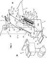
- the platform 3 When the platform 3 is in the low position, represented on the figures 1 and 3 , its bottom 30 is at ground level S or substantially at ground level S (that is to say at a short distance from it), so that an operator can load or unload the object O.
- the overhead door 33 can pivot further towards the ground to make up the difference in level between the ground S and the bottom 30 and facilitate the transfer of the object O on the bottom 30 from the ground S and vice versa.
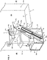
- the platform 3 When the platform 3 is in the high position, represented on the figure 2 it is at an altitude higher than that of the low position. It is then at a level that allows the movement of the vehicle. In this high position, the bottom 30 is at the same height as the floor of the vehicle 1, which can move the object O to the inside of the latter, or at a position slightly lower than the floor. In the latter case, the object O then remains in place on the bottom 30, without being able to be moved inside the vehicle.
- the slideway 41 and the slider 42 are preferably fixed respectively on the platform 3 and on the chassis 2, so that the slide is fully retracted into the slide, when the platform 3 is in the down position (see figure 3 ) and that the slide 42 is released to the maximum of the slide 41, when the platform 3 is in the up position, (see figure 2 ).
- these locking means comprise two hooks 60a, 60b, pivotally mounted respectively with respect to the lateral flanks 20a, 20b, these hooks, called “first hooks”, being arranged horizontally opposite each other.
- the hook 60a consists of a thin plate having three lobes arranged around a central orifice 61a.
- the hook 60a is pivotally mounted about an axis 270a integral with the side 20a of the frame and which extends through the orifice 61a.
- One of the lobes is an end 62a curved upwardly and rearwardly and adapted to cooperate with a locking pin 36a fixed on the outer face of the flange 321a.
- a second lobe located substantially opposite to the end 62a with respect to the orifice 61a constitutes a control end 63a, on which it is possible to act to pivot the hook 60a, around an integral axis 270a. a plate 27a, itself fixed on the inner face of the sidewall 20a.
- the hook 60a can thus pivot in a locking position (clockwise), in which it holds the finger 36a and conversely in an unlocking position (counterclockwise), in which it releases it.
- these locking means 6 are automatic locking means.
- the control end 63a is connected, on the one hand, to a return spring 64a, and on the other hand, in an articulated manner, to a actuating member 65a, here a rod, which acts in the opposite direction of the spring 64a.
- the other end of the return spring 64a is fixed on the plate 27a.
- a gripping bar 28 (see figures 2 and 3 ), to which the operator can hook, is mounted horizontally between the two sides 20a and 20b, perpendicular thereto, and at a short distance backwards relative to said first locking hooks 60a and 60b.
- An actuating handle 280 is pivotally mounted at both ends of this bar 28.
- the actuating handle 280 comprises a horizontal rod 281 at both ends of which are fixed two tabs 282a, 282b perpendicular. These tabs are pivotally mounted at their free end around the bar 28.
- the rods 65a, 65b are fixed respectively to these two tabs 282a, 282b, by an articulated connection.
- the third lobe of the hook 60a defines a third end 66a disposed between the two curved ends 62a and control 63a.
- a connecting rod or rod 67a is fixed at its two ends, in an articulated manner, on the one hand at the end 66a of the first hook 60a and on the other hand, at one end 73a of a second hook 70a which constitutes one locking means 7 of the platform 3 in the low position.
- This rod 67a provides the kinematic connection between the two hooks, and therefore their simultaneous movement.
- these locking means also comprise another second hook 70b identical to the hook 70a and whose component parts bear the same numerical references plus the letter "b".
- the second hook 70a is pierced with a hole 71a around which it is pivotally mounted about an axis 280a integral with a plate 28a, itself fixed on the inner face of the frame 2, more precisely the sidewall 20a.
- the hook 70a has two lobes extending substantially at right angles to one another, one defining an end 72a curved downwardly and forwards, and the other end 73a aforementioned control end.
- the end 72a is adapted to cooperate with the teeth of a rack 37a fixed on the outer face of the oblong wing 321a of the platform 3.
- This rack 37a extends parallel to the slideway 41.
- the hook 70a and more particularly its curved end 72a are close to the rack 37a.
- the return spring 64a via the rod 67a tends permanently to pivot the hook 70a in its locking position, in which its end 72a cooperates with one of the teeth of the rack 37a.
- the operator pulls on the rod 281 he also brings the hook 70a into its unlocked position.
- the elastic deformation device 5 comprises a fixed part mechanically linked to the frame 2 and an elastically deformable or elastically movable part, mechanically linked to the mobile platform 3.
- This device 5 is able to deform under the action of the force (weight) that the operator and / or object O exerts on the device 5 because of its mass and its position in the gravitational field.
- the operator increases his potential energy in the field of terrestrial gravitation.
- the device 5 is capable of accumulating this potential energy, provided by at least one operator mounted on the mobile platform 3 when it is in the up position and / or provided by the object O placed on this mobile platform during the downward movement of the platform 3 to the low position.
- this elastic deformation device 5 is then capable of restoring this potential energy substantially constant and with a controlled speed, said mobile platform 3 to ensure, in whole or in part accompanying an additional driving force, the upward movement thereof.
- gas cylinder 50 comprising a sealed body 51 containing a compressed gas and oil, a piston and a rod 52.
- the free end 510 of the body 51 is fixed to the frame 2, more precisely on the inside face of the side wall 23a of the well 24.
- the free end 520 of the rod 52 is, in turn, fixed to the platform 3 and, more precisely, on the outer face of the oblong portion 321a of the cage.
- a gas cylinder 50 on each side of the platform 3, more preferably two on each side, as shown in the figures, and this, for reasons of safety in order to prevent a possible mechanical failure of one of them.
- the gas spring 50 is advantageously a thrust spring, that is to say that its rest position is that in which the rod is out (see figure 2 ).
- the cylinder 50 contains advantageously comprises an internal damping device limiting its retraction speed.
- the gas cylinder 50 is set so that its resistant force in the downward vertical direction is equal to or slightly less than or slightly greater than the force created, on the slides, by the weight of the platform 3 and the object O.
- the elevator according to the invention is dedicated to the handling of a specific object O, for example here the rammer, this object has a known weight and the aforementioned adjustment is easy. We'll see later, in another embodiment, when the elevator is intended to move different objects, so different weights, some adjustments may be necessary.
- This complementary muscular force can be applied either directly by the operator who raises the platform 3, or with the aid of a complementary lifting device.
- the device 8 comprises two chains or transmission cables 80a, 80b, one end of which is fixed to the flange 321a, respectively 321b, of the platform 3 and the other to one of the branches 810a, respectively 810b of a control lever. 81 inverted U-shaped control.
- This control lever 81 is pivotally mounted, at its lower free ends, about axes 29a, respectively 29b, formed on integral plates of the frame 2.
- each transmission chain 80a, 80b meshes with a pinion, rotatably mounted on the plate 27a, 27b.
- a single pinion, referenced 82 is visible in the figures. This pinion is placed higher than the end of the wings 321a, 321b.
- springs 83a, 83b maintain the chains 80a, 80b in a state of permanent tension.
- the actuating handle 280 is advantageously supported by the control lever 81 in place of the bar 28.
- the rammer C is on the platform 3 in high position.
- the operator pulls on the two safety locks which block the sliding of the platform relative to the frame 2 (not described) and then actuates the actuating handle 280 so as to release the locking fingers 36a, 36b.
- the platform 3 then begins to descend under the weight of the rammer if the cylinders 5 exert a lower upward force than the vertical downward force of gravity.
- the operator exerts directly on the platform 3 and / or on the object O, that is to say a complementary muscular effort to bring them down, or rises beforehand on the gate 33 of the platform 3 to bring the additional weight missing.
- the descent movement of the platform 3 stops when the latter reaches either the ground level or the mechanical limit position of the lower position of the slide 42 relative to the slideway 41, or the limit of the stroke of the gas cylinders 50
- the locking hooks 70a, 70b then engage automatically in the racks 37a, 37b. Note that the height of the locking position in the lower position of the platform 3 is equal to or just greater than the stop position of this platform in contact with the ground or at the end of mechanical travel.
- the operator can then actuate the lock 35 of the door 33 and tilt it horizontally outwards.
- the platform 3 then begins its upward movement under the thrust of gas springs 50 and mastered under the effect of their internal dampers.
- the operator holds the handle 280 in the unlocked position of the hooks 70a, 70b approximately halfway, that is to say after the racks 37a, 37b are no longer in correspondence of the hooks 70a, 70b, so that to avoid their inadvertent re-engagement.
- the platform 3 is automatically locked under the action of the locking hooks 60a, 60b.
- the hooks 60a and 60b deviate automatically at the passage of the locking fingers 36a, 36b and then close again.
- the fingers 36a, 36b do not remain in abutment against the hooks 60a, 60b because, the platform 3 being empty, the gas springs 50 are held in abutment of their own mechanical end position (relaxed position).
- the platform 3 goes on the platform 3 and then actuates the handle 280 so as to unlock the upper locking means 60a, 60b, the platform 3 then drops under the weight of the operator.
- the weight of the operator is insufficient to lower the platform, it can take with it an additional charge or exercise a complementary downward muscle force or call a second operator who will also exert his weight on the platform.
- the gas springs 50 compress and accumulate the potential energy of the operator during the descent of the platform 3.
- the operator can then place the rammer C on the platform with the door open, close the door and unlock the locking means 7 of the platform in the low position.
- the gas springs 50 restore the energy they accumulated during the previous descent, which has the effect of causing the upward movement of the platform.
- the platform 3 then locks automatically in the up position.
- This variant differs from the previous one in that the platform, referenced 3 ', deploys from inside the vehicle to a horizontal position outside the vehicle 1.
- the platform 3 ' comprises a plate 300' pivotally mounted relative to two vertical uprights 420a, 420'b.
- the deployment of the plate 300 ' can be done by tilting about an axis 301' of a vertical position not exceeding the outer contours of the vehicle to a horizontal position overflowing the vehicle, as shown in the attached diagram, and thanks to opening / closing compasses 311'a, 311'b which connect the plate 300 'to the uprights 420a, 420b.
- the deployment can also be done by sliding in a horizontal plane from the inside of the vehicle to the outside, the goods can then remain on the platform when it is in position on or in the vehicle.
- the set of axes 301 ' is then replaced by a set of double rollers (not shown) linked by a support to the vertical uprights 420a and 420b and each sliding in a slide disposed on the outer lateral edges of the platform.
- the amounts 420a, 420b constitute the movable portion (slider) of at least one vertical or substantially vertical slide 410a, 410b of a displacement guide device 4 "of the platform 3 'relative to the frame 2.
- These slides 410a, 410b are formed on the inner faces (facing one another) of columns 211a, 211b, secured to the frame 2.
- Each movable slider 420a, 420b is mechanically connected to a first elastic end of a device with elastic deformation or its elastically movable part, here respectively at the free end of the rod 52a, 52b of a gas cylinder 5'a , 5'b. It is preferably gas cylinders called "traction", whose rod is returned to the body at rest. This connection is effected by a chain 53a, respectively 53b.
- the second ends of the elastic devices 5'a, 5'b ie the bodies 51a, 51b of the cylinders) are fixed to the frame 2 of the vehicle.
- the jacks 5'a, 5'b are arranged vertically or substantially vertically, parallel to the slides 410a, 410b and the slides 420a, 420b.
- Each chain 53a, 53b meshes respectively with a pinion 54a, 54b, rotatably mounted at the upper end of the fixed columns 211a, 211b.
- a downward movement of the rods 52a, 52b respectively causes upward movement of the slides 420a, 420b and vice versa.
- the locking device 6 'of the platform in the up position and the locking device 7' of the platform in the low position are quite similar to the locking devices 6 and 7 previously described and will be described more succinctly. These locking devices are provided on the two fixed columns 211a, 211b.
- the device 6 comprises a pivoting hook 60 'and the device 7', a pivot hook 70 '.
- An axis 61 ' is pivotally mounted in a horizontal bearing of the column 211a and rigidly connects the hook 60' to an actuating handle 280 'placed on the other side of the column 211a.
- the axis 71 'of each hook 70' consists of a torsion bar automatically realizing its return in the locked position.
- the end of the hook side torsion bar 70 'pivots in a bearing and its opposite end is fixed rigidly to the column 211a, respectively 211b.
- the hooks 60 ', 70' can cooperate with a locking pin 411 fixed on the uprights 420a, 420b of the platform 3 '. Both hooks 60 ', 70' are interconnected by a rod 67 'which synchronizes their locking or unlocking movements.
- a hollow tube 283 connects the pinions 54a, 54b of the two guide columns 211a, 211b to synchronize the vertical movements of the slides 420a and 420b.
- the operator can thus act indifferently on the handle 280 'right or left to control the unlocking high position or low position of the platform.
- the elastic deformation device 5'a, 5'b used is sized to be able to accumulate the potential energy of the gravitational field of at least one operator and / or the object during the descent of the platform 3 'of a high position locked vertically to a low position also locked vertically.
- the vertical thrust force of this elastic deformation device is dimensioned according to the weight of the platform, the weight of the object O to be mounted in the vehicle, as well as the weight of one or more operators.
- the direction of movement is determined by the resultant force of two opposing forces: the upward vertical thrust of the potential energy accumulator elastic device 5'a, 5'b on the one hand and the downward vertical thrust generated by the weight of the platform 3 'and the load consisting of at least one operator and / or the object O to get off the vehicle or to board the vehicle.
- the weight of the 3 'platform has been intentionally neglected to simplify the presentation.
- the upward vertical thrust of the potential energy storage elastic deformation device 5'a, 5'b is 1000N.
- the operator weighs 70 kg. He wants to load an object with a weight of 80 kg on or in the vehicle, he must first rotate the platform 3 'to outside and then down. To do this, he rides in or on the vehicle 1. By raising his body with ease thanks to an excellent natural energy efficiency, the operator increases his potential energy in the field of gravity.
- the elastic energy storage device 5'a, 5'b In a second step, it will restore this potential energy to the elastic energy storage device 5'a, 5'b, as follows: it is installed on the platform with one or more additional unit loads of a total of 20 kg, forming a total mass of 110 kg. The operator can also mount a second operator.
- the platform 3 In a third step, the platform 3 'rises under the action of the elastic device 5'a, 5'b whose thrust of 1000N is greater than the weight of 80 kg of the object.
- the assembly represents a mass of 120 kg whose gravitational downward force is greater than the upward thrust of 1000N of the elastic accumulation device 5'a, 5'b.
- the operator releases the locking device in the high position of the platform.
- the latter released vertically, descends damply to the ground.
- the 3 'platform automatically locks in the down position.
- the operator removes the object from the platform. It can then raise the latter free of any load, under the effect of the permanent thrust of the elastic device damped speed until its automatic locking in the high position, the thrust of the device being greater than the empty weight of the platform 3 .
- the operator can also climb on the platform which then brings it back to the floor of the vehicle.
- the operator can exert an upward muscular effort of 20 kg directly on the platform 3 'or on the object.
- the 1000 N of vertical thrust of the elastic device 5'a, 5'b will prove to be insufficient and the muscular effort too important. In this case, it is necessary to use a complementary lifting device.
- This device 8 comprises a step 84 slidably mounted on one of the columns, here the column 211b.
- the step 84 is integral with a plate 840 which slides in a slideway 2110b provided on the outer face of the column 211b.
- the upper end 8400 of the plate 840 is mechanically connected to the descending strand of the chain 53b, the ascending strand pulls the platform 3 'upwards, the pinion 54b placed at the top of the column 211b effecting a 360 ° return of the movement .
- the step 84 is foldable upwards.
- the operator After installing the object O on the platform 3 'in the down position, the operator rises again on or in the vehicle raising a second time its potential energy. It then brings the additional upward force of about 700 N by climbing on the step 84.
- the platform 3 'can then climb with its load of 150 kg whose gravitational force is lower than the total upward traction of 1700 N.
- Such a device comprises a movable valve which obstructs the piston opening of the cylinder, which blocks the latter in position because the fluid can not then move from one chamber to another.
- This valve is actuated by a lever or control cable from outside the cylinder via a rod which slides in the piston rod.
- the thrust force can for example be adapted by using means for subtracting or adding fluid into the enclosure of the cylinder.
- the elastic deformation device 5, 5'a, 5'b consists of several elementary elastic devices forming an assembly ensuring maximum thrust of the platform from bottom to top along its slide
- a simple mechanical device allows subtracting one or more ends of at least one elementary elastic device from its point of attachment to the movable part of the platform 3 ', so as to reduce the upward vertical thrust to the necessary value which is a function of the weight of the object to lift.
- the thrust of the elastic deformation device can be adjusted using a lever with variable arm length.
- the full thrust force of the elastic deformation device is exerted on the platform by means of a lever with variable arm length to reduce the transmitted force.
- This thrust reduction device of the elastic device allows the operator to ensure the descent of the platform when the object, which is placed therein, has a mass insufficient to overcome the full thrust of the elastic device.
Description
L'invention se situe dans le domaine de la manutention et du levage d'objets.The invention lies in the field of handling and lifting objects.
La présente invention concerne un véhicule, notamment un véhicule utilitaire, équipé d'un monte-charge permettant de charger et de décharger des objets lourds dans/sur et hors de ce véhicule.The present invention relates to a vehicle, in particular a commercial vehicle, equipped with a freight elevator for loading and unloading heavy objects in / on and out of this vehicle.
Il s'agit d'objets dont le poids est tel qu'il ne permet pas leur chargement ou leur déchargement par un opérateur seul, c'est-à-dire un poids compris entre 20 kg et 150 kg environ.These are objects whose weight is such that it does not allow their loading or unloading by a single operator, that is to say a weight of between 20 kg and 150 kg approximately.
Par "objet", on entend tout type de marchandises, matériels, fournitures, matériaux divers, machines, outillage ou appareils mobiles."Object" means any type of goods, materials, supplies, miscellaneous materials, machinery, tools or mobile devices.
Une application particulière de l'invention représentée sur les dessins concerne la manutention d'une machine de chantier, tel qu'une pilonneuse. De façon non limitative, il pourrait également s'agir à titre d'exemple d'une plaque vibrante, d'une pompe, d'un groupe hydraulique ou électrogène, d'un appareil électroménager, d'une cabine de toilettes publiques mobile ou d'un objet en béton.A particular application of the invention shown in the drawings relates to the handling of a construction machine, such as a rammer. Without limitation, it could also be an example of a vibrating plate, a pump, a hydraulic power unit or generator, a household appliance, a mobile public toilet cabin or of a concrete object.
On connaît déjà dans l'état de la technique, différents dispositifs de levage permettant de déplacer des objets du niveau du sol jusqu'à l'intérieur d'un véhicule et inversement. Il s'agit notamment de dispositifs manuels faisant appel à la force humaine ou actionnés par la force humaine ou encore de dispositifs mécanisés fonctionnant avec un apport extérieur d'énergie.Already known in the state of the art, various lifting devices for moving objects from ground level to the inside of a vehicle and vice versa. These include manual devices using human force or actuated by human force or mechanized devices operating with an external supply of energy.
L'inconvénient d'un dispositif faisant appel à la force humaine, tel qu'une rampe inclinée, est qu'il nécessite que les opérateurs déploient une force importante pour pousser ou tirer l'objet et le déplacer progressivement sur la rampe. En outre, cette opération s'accompagne d'un risque de chutes ou de blessures de l'opérateur parfois élevé.The disadvantage of a device employing human force, such as an inclined ramp, is that it requires the operators deploy a large force to push or pull the object and move it gradually on the ramp. In addition, this operation is accompanied by a risk of falls or injuries of the operator sometimes high.
Un dispositif actionné par la force humaine, tel que par exemple une poulie, un palan ou un système hydraulique manuel, bien qu'il présente l'avantage de réduire la puissance musculaire instantanée nécessaire au levage, présente également l'inconvénient de rallonger de façon importante la durée de l'opération de manutention.A device actuated by human force, such as for example a pulley, a hoist or a manual hydraulic system, although it has the advantage of reducing the instantaneous muscular power required for lifting, also has the disadvantage of lengthening important the duration of the handling operation.
En outre, l'emploi de tels dispositifs est très encadré, voire interdit pour certains par la réglementation du travail, en raison des risques d'accidents ou de maladies professionnelles.In addition, the use of such devices is highly regulated, or even prohibited for some by the regulation of work, because of the risk of accidents or occupational diseases.
Enfin, les inconvénients des dispositifs nécessitant un apport extérieur d'énergie, par exemple d'énergie électrique, hydraulique, magnétique ou pneumatique, sont leur coût élevé, leur frais de maintenance et la nécessité d'un contrôle régulier obligatoire comme pour les hayons élévateurs hydrauliques de véhicules par exemple.Finally, the drawbacks of the devices requiring an external supply of energy, for example electrical, hydraulic, magnetic or pneumatic energy, are their high cost, their maintenance costs and the need for a regular mandatory inspection, such as for tail lifts. hydraulic vehicles for example.
On connaît également d'après le document
L'opérateur, à l'aide d'une poignée située sur la plateforme, peut faire pivoter manuellement le bras pivotant, de façon à le faire passer d'une position de "rangement" dans laquelle son extrémité supérieure est légèrement basculée vers l'intérieur du véhicule et la plateforme est dans le véhicule, à une position dite "de point haut" dans laquelle il est vertical et enfin, à une position de "déchargement" dans laquelle son extrémité supérieure est basculée vers l'extérieur du véhicule et la plateforme est au sol.The operator, by means of a handle on the platform, can manually rotate the swivel arm, so as to move it from a "storage" position in which its upper end is slightly tilted towards the vehicle interior and the platform is in the vehicle, to a so-called "high point" position in which it is vertical and finally to an "unloading" position in which its upper end is tilted towards the outside of the vehicle and the platform is on the ground.
Lors de ce mouvement de pivotement du bras vers l'extérieur, le vérin à gaz s'allonge et accumule de l'énergie qu'il peut restituer lors du mouvement inverse.During this pivoting movement of the arm to the outside, the gas cylinder elongates and accumulates energy that it can restore during the reverse movement.
Ce dispositif de monte-charge présente de nombreux inconvénients énumérés ci-après.This elevator device has many disadvantages listed below.
Il nécessite obligatoirement l'utilisation de la force musculaire de l'opérateur notamment de ses bras, de sorte que la puissance développée est limitée.It necessarily requires the use of the muscular force of the operator including his arms, so that the power developed is limited.
Par ailleurs, l'effort musculaire est obligatoirement simultané au mouvement de déplacement de la plateforme et l'effort de levage varie de façon importante pendant la course de la plateforme qui doit passer par un point haut. Les muscles de l'opérateur sont donc fortement sollicités, notamment pendant la descente de la plateforme, ou alors le poids de l'objet à décharger doit être limité.Moreover, the muscular effort is necessarily simultaneous with the movement of movement of the platform and the lifting force varies significantly during the race of the platform which must pass through a high point. The muscles of the operator are therefore highly stressed, especially during the descent of the platform, or the weight of the object to be unloaded must be limited.
Enfin, le mouvement de la plateforme devant être effectué par un effort musculaire de l'opérateur, il est nécessairement lent.Finally, the movement of the platform to be performed by a muscular effort of the operator, it is necessarily slow.
Un objectif de l'invention est de pallier les inconvénients précités.An object of the invention is to overcome the aforementioned drawbacks.
L'invention a donc pour but de proposer un véhicule équipé d'un dispositif qui permette à un opérateur de lever ou de descendre des objets entre le sol et ce véhicule, sans effort, de façon rapide, sécurisée et sans apport d'une énergie extérieure.The invention therefore aims to propose a vehicle equipped with a device that allows an operator to lift or lower objects between the ground and the vehicle, effortlessly, quickly, safely and without input of energy exterior.
L'invention a également pour but d'offrir un dispositif de déplacement de l'objet qui soit simple, robuste et nécessite peu d'entretien.The invention also aims to provide a device for moving the object that is simple, robust and requires little maintenance.
A cet effet, l'invention concerne un véhicule, notamment véhicule utilitaire, équipé d'un monte-charge configuré pour déplacer un objet, telle qu'une machine de chantier, du sol vers l'intérieur du véhicule et inversement, ce monte-charge comprenant :
- un châssis fixe solidarisé audit véhicule,
- une plateforme support dudit objet, mobile par rapport audit châssis, selon un mouvement ascendant, entre une position, dite "basse", dans laquelle elle est au niveau du sol ou sensiblement au niveau du sol, de façon à autoriser le chargement ou le déchargement dudit objet depuis ou vers le sol par un opérateur, et une position, dite "haute", et inversement selon un mouvement descendant,
- au moins un moyen de guidage en déplacement de ladite plateforme par rapport audit châssis,
- au moins un moyen de verrouillage de ladite plateforme en position haute.
- a fixed frame secured to said vehicle,
- a support platform of said object, movable relative to said frame, in an upward movement, between a position, called "low", in which it is at ground level or substantially at ground level, so as to allow the loading or unloading said object from or to the ground by an operator, and a position, called "high", and vice versa in a downward movement,
- at least one guide means for moving said platform relative to said frame,
- at least one locking means of said platform in the high position.
Conformément à l'invention, ledit moyen de guidage en déplacement comprend une glissière et un coulisseau dont l'un est solidaire de ladite plateforme mobile et l'autre solidaire du châssis, de façon à réaliser un mouvement de translation de la plate-forme par rapport audit châssis, dans un sens vertical ou sensiblement vertical entre lesdites positions basse et haute de la plateforme, et ce monte-charge comprend :
- au moins un moyen de verrouillage de ladite plateforme en position basse,
- au moins un dispositif à déformation élastique, dont une partie fixe est liée mécaniquement audit châssis et dont une partie déformable élastiquement ou mobile élastiquement est liée mécaniquement à ladite plateforme mobile,
- accumuler, pendant le mouvement de translation descendant de la plateforme jusqu'à sa position basse, l'énergie potentielle du champ de la pesanteur fournie préalablement par au moins un opérateur monté sur la plateforme mobile lorsqu'elle est en position haute ou fournie préalablement par au moins un opérateur monté sur la plateforme mobile (3, 3') et par l'objet placé sur la plateforme mobile lorsqu'elle est en position haute,
- contrôler la vitesse de descente de la plateforme mobile,
- restituer cette énergie potentielle accumulée d'une façon sensiblement constante et avec une vitesse contrôlée, à ladite plateforme mobile, pour assurer, en totalité ou en accompagnement, le mouvement ascendant de celle-ci.
- at least one locking means of said platform in the low position,
- at least one elastic deformation device, a fixed part of which is mechanically linked to said frame and of which an elastically deformable or resiliently movable part is mechanically connected to said mobile platform,
- accumulate, during the downward translation movement of the platform to its low position, the potential energy of the gravitational field previously supplied by at least one operator mounted on the mobile platform when it is in the up position or previously supplied by at least one operator mounted on the mobile platform (3, 3 ') and the object placed on the mobile platform when it is in the high position,
- control the speed of descent of the mobile platform,
- restoring this potential energy accumulated in a substantially constant manner and with a controlled speed, to said mobile platform, to ensure, in full or accompanying, the upward movement thereof.
Ce dispositif présente l'avantage d'utiliser le fait qu'un être humain peut accumuler de l'énergie potentielle avec un rendement particulièrement élevé grâce à des déplacements naturels de son corps, comme le fait de monter sur une plateforme ou un plancher de véhicule ce qui correspond sensiblement au fait de monter sur une ou plusieurs marches.This device has the advantage of using the fact that a human being can accumulate potential energy with a particularly high efficiency through natural movements of his body, such as mounting on a platform or a vehicle floor which corresponds substantially to climbing one or more steps.
Cet avantage est utilisé pour ensuite accumuler et restituer cette énergie potentielle à l'aide d'un dispositif approprié et ainsi soulever un objet à moindre effort pour l'opérateur.This advantage is used to then accumulate and restore this potential energy using a suitable device and thus lift an object with less effort for the operator.
Selon d'autres caractéristiques avantageuses et non limitatives de l'invention, prises seules ou en combinaison :
- le dispositif à déformation élastique est un vérin à gaz dont la poussée est sensiblement constante et la vitesse contrôlée et qui comprend un corps et une tige mobile dont l'un est solidaire de la plateforme et l'autre est solidaire du châssis ;
- ledit vérin à gaz est configuré pour présenter une force ascendante supérieure au poids de la plateforme mobile et de l'objet à déplacer, de façon à assurer en totalité l'ascension autonome de la plateforme avec l'objet ;
- le vérin à gaz a une force ascendante inférieure au poids de la plateforme mobile et de l'objet à déplacer et en ce que le monte-charge comprend un dispositif de levage complémentaire actionné par la force musculaire de l'opérateur ou le poids de son corps dans le champ gravitationnel ;
- le dispositif de levage complémentaire comprend un levier de commande actionnant par poussée ou tirage un câble ou une chaîne reliée mécaniquement à la plateforme mobile ;
- le dispositif de levage complémentaire comprend un marchepied actionnant un câble ou une chaîne reliée mécaniquement à la plateforme mobile ;
- les moyens de verrouillage de la plateforme en position haute et/ou les moyens de verrouillage de la plateforme en position basse comprennent une soupape mobile d'obstruction de l'orifice du piston d'un vérin qui empêche le fluide présent dans le vérin de passer d'une chambre à l'autre de celui-ci ;
- le châssis fixe est équipé d'une barre rigide permettant à l'opérateur de s'y accrocher pour faciliter et sécuriser son ascension sur la plateforme mobile, cette barre rigide étant équipée d'au moins une poignée d'actionnement des moyens de verrouillage de la plateforme en position haute et/ou des moyens de verrouillage de la plateforme en position basse ;
- les moyens de verrouillage de la plateforme en position haute comprennent un crochet, dit "premier crochet", monté pivotant autour d'un axe fixé au châssis et dont l'extrémité recourbée est configurée pour coopérer avec un doigt de verrouillage solidaire de la plate-forme mobile ;
- les moyens de verrouillage de la plateforme en position haute sont des moyens de verrouillage automatique, en ce que le premier crochet est équipé d'un ressort de rappel qui tend en permanence à le ramener en position verrouillée et en ce que lesdits moyens de verrouillage comprennent un organe d'actionnement qui permet de faire pivoter ledit premier crochet à l'encontre de la force du ressort de rappel pour l'amener dans une position déverrouillée dans laquelle il libère ledit doigt de verrouillage ;
- les moyens de verrouillage de la plateforme en position basse comprennent un crochet, dit "deuxième crochet", monté pivotant autour d'un axe fixé au châssis et dont l'extrémité recourbée est configurée pour coopérer avec une crémaillère solidaire de la plate-forme ;
- le premier crochet et le deuxième crochet sont liés de façon cinématique, de sorte que leurs placements en position verrouillée ou déverrouillée sont concomitants ;
- la plate-forme est équipée d'au moins un amortisseur permettant de contrôler sa vitesse de montée ou de descente ;
- le véhicule comprend un dispositif d'ajustement de la force de poussée exercée par le ou les dispositifs à déformation élastique.
- the device with elastic deformation is a gas cylinder whose thrust is substantially constant and controlled speed and which comprises a body and a movable rod, one of which is integral with the platform and the other is secured to the frame;
- said gas cylinder is configured to have an upward force greater than the weight of the mobile platform and the object to be moved, so as to fully ensure the autonomous ascension of the platform with the object;
- the gas cylinder has an upward force lower than the weight of the mobile platform and the object to be moved and that the elevator includes an additional lifting device operated by the operator's muscular force or the weight of his body in the gravitational field;
- the complementary lifting device comprises a control lever actuating by pushing or pulling a cable or a chain mechanically connected to the mobile platform;
- the complementary lifting device comprises a step operating a cable or a chain mechanically connected to the mobile platform;
- the locking means of the platform in the raised position and / or the locking means of the platform in the low position comprise a movable valve for obstruction of the piston orifice of a jack which prevents the fluid present in the jack from passing from one room to another of this one;
- the fixed frame is equipped with a rigid bar allowing the operator to hang on to facilitate and secure his ascent on the mobile platform, this rigid bar being equipped with at least one operating handle locking means of the platform in the up position and / or locking means of the platform in the low position;
- the locking means of the platform in the high position comprises a hook, called "first hook", pivotally mounted about an axis fixed to the frame and whose curved end is configured to cooperate with a locking pin integral with the platform; mobile form;
- the locking means of the platform in the high position are automatic locking means, in that the first hook is equipped with a return spring which constantly tends to bring it back to the locked position and in that said locking means comprise an actuating member for pivoting said first hook against the force of the return spring to bring it into an unlocked position in which it releases said locking finger;
- the locking means of the platform in the low position comprises a hook, said "second hook", pivotally mounted about an axis fixed to the frame and whose curved end is configured to cooperate with a rack integral with the platform;
- the first hook and the second hook are connected kinematically, so that their placements in the locked or unlocked position are concomitant;
- the platform is equipped with at least one damper to control its speed of ascent or descent;
- the vehicle comprises a device for adjusting the thrust force exerted by the elastic deformation device or devices.
D'autres caractéristiques et avantages de l'invention apparaîtront de la description qui va maintenant en être faite, en référence aux dessins annexés, qui en représentent, à titre indicatif mais non limitatif, différents modes de réalisation possibles.Other features and advantages of the invention will appear from the description which will now be made, with reference to the accompanying drawings, which represent, by way of indication but not limitation, various possible embodiments.
Sur ces dessins :
- la
figure 1 représente une vue en perspective d'un véhicule utilitaire, équipé du monte-charge conforme à l'invention, - les
figures 2 et 3 sont des vues partielles, en perspective, d'un premier mode de réalisation du monte-charge conforme à l'invention, respectivement en position haute et basse, - la
figure 4 est une vue de côté partielle de la plateforme du monte-charge de lafigure 3 , - la
figure 5 est une vue partielle, en perspective, des moyens de verrouillage de la plateforme en position haute et basse, - les
figures 6 sont des vues en perspective, d'une partie du monte-charge deset 7figures 2 et 3 et d'un dispositif de levage complémentaire, - la
figure 8 est une vue en perspective d'un deuxième mode de réalisation du monte-charge conforme à l'invention, et - la
figure 9 est une vue de détail d'un élément de lafigure 8 .
- the
figure 1 represents a perspective view of a utility vehicle, equipped with the freight elevator according to the invention, - the
figures 2 and3 are partial views, in perspective, of a first embodiment of the freight elevator according to the invention, respectively in high and low position, - the
figure 4 is a partial side view of the elevator platform of thefigure 3 , - the
figure 5 is a partial view, in perspective, locking means of the platform in high and low position, - the
Figures 6 and 7 are perspective views of part of the goods liftfigures 2 and3 and a complementary lifting device, - the
figure 8 is a perspective view of a second embodiment of the freight elevator according to the invention, and - the
figure 9 is a detail view of an element of thefigure 8 .
En se reportant à la
Dans l'exemple représenté sur les figures, cet objet O est une machine de chantier, et plus précisément une pilonneuse.In the example shown in the figures, this object O is a construction machine, and more specifically a rammer.
Selon un premier mode de réalisation représenté sur les
Plusieurs modes de réalisation de ces différents éléments vont maintenant être décrits plus en détail.Several embodiments of these different elements will now be described in more detail.
Le châssis 2 est fixé sur le véhicule et est constitué d'une pluralité de profilés et de tôles métalliques, assemblés entre eux de façon à définir une structure ayant sensiblement la forme générale d'un parallélépipède rectangle. Les profilés forment les montants et les longerons de la structure.The
De préférence, ce châssis 2 est disposé perpendiculairement à l'axe longitudinal médian X-X' du véhicule 1 et débouche côté passager du véhicule 1.Preferably, this
Dans la suite de la description et des revendications, par convention, on désignera le côté avant AV du monte-charge 10 (à gauche sur la
Comme on peut le voir sur les
Une autre tôle rectangulaire plus étroite est pliée à angle droit, de façon à présenter une partie horizontale, qui constitue le fond 21 du châssis, et une partie verticale qui s'étend vers le bas et qui constitue une paroi arrière 22.Another narrower rectangular sheet is folded at right angles, so as to have a horizontal part, which constitutes the bottom 21 of the frame, and a vertical part which extends downwards and which constitutes a
Le fond 21 relie entre eux les deux flancs latéraux 20a et 20b, par leurs bords inférieurs respectifs, sauf dans la partie arrière du châssis 2.The bottom 21 interconnects the two
Deux tôles supplémentaires 23a et 23b, rectangulaires ou carrées, sont fixées dans le prolongement du bord inférieur arrière de chacune des deux flancs latéraux 20a et 20b. Elles sont parallèles l'une à l'autre, verticales et sont dénommées "parois latérales". Ces parois latérales 23a et 23b délimitent avec la paroi arrière 22, un puits 24, à l'intérieur duquel est déplacée la plateforme 3.Two
Enfin, de préférence, les deux flancs latéraux 20a, 20b sont reliés à leur partie supérieure par une tôle 25, qui assure la rigidification de l'ensemble de la structure.Finally, preferably, the two
On notera que la forme et les dimensions du châssis 2 peuvent être adaptées différemment en fonction de nature et des dimensions de l'objet O que l'on souhaite charger dans le véhicule 1. Le châssis 2 a pour rôle de permettre la fixation des autres éléments 3 à 7.Note that the shape and dimensions of the
La plateforme support 3 est également réalisée à l'aide de plusieurs tôles métalliques, assemblées entre elles par des moyens appropriés, tels que vissage, boulonnage ou soudage.The
De façon avantageuse, la plateforme 3 comprend un fond 30 horizontal et une paroi arrière verticale 31, préférentiellement de forme carrée ou rectangulaire, ainsi que deux parois latérales 32a, 32b.Advantageously, the
Chaque paroi latérale 32a, 32b comprend une partie rectangulaire 320a, 320b, qui se prolonge entre son coin supérieur avant et la partie centrale de son arête supérieure, par une aile 321a, 321b de forme oblongue, inclinée vers le haut et vers l'avant.Each
De façon avantageuse, la plateforme 3 comprend également une porte 33, de préférence une porte basculante, montée pivotante vers l'arrière autour d'un axe de rotation 34. Cet axe 34 s'étend à la partie inférieure de la porte et entre les deux angles inférieurs arrière des deux parois latérales 32a, 32b.Advantageously, the
De façon avantageuse, la partie supérieure de cette porte 33 présente un biseau intérieur 330 qui définit une rampe inclinée, facilitant l'introduction de l'objet O sur le fond 30.Advantageously, the upper part of this
De préférence, la porte 33 présente des moyens de verrouillage 35, qui coopèrent avec les deux parois latérales 32a et 32b, afin de la maintenir en position fermée verticale, pendant le déplacement de la plateforme support 3.Preferably, the
La plateforme 3, avec son fond 30, sa paroi arrière 31, ses parois latérales 32a, 32b et sa porte 33, forme une cage qui se déplace à l'intérieur du puits 24.The
De préférence également, l'une des parois verticales de la plateforme 3 peut présenter des moyens d'immobilisation de l'objet O, (non représentés), afin d'éviter tout déplacement intempestif de celui-ci pendant le déplacement du véhicule 1.Also preferably, one of the vertical walls of the
Un mode possible de réalisation des moyens de guidage 4 va maintenant être décrit en faisant référence aux
De préférence, des moyens de guidage 4 identiques sont disposés de part et d'autre des deux côtés de la plateforme 3. Seul l'un d'entre eux sera décrit ici plus en détail.Preferably, identical guiding means 4 are arranged on either side of both sides of the
Le moyen de guidage 4 comprend une glissière 41, à l'intérieur de laquelle un coulisseau mobile 42 est guidé en translation. L'un de ces éléments est fixé au châssis 2 et l'autre à la plateforme support 3.The guiding means 4 comprises a
De préférence, la glissière 41 est fixée sur la face extérieure de l'aile 321a tandis que le coulisseau 42 est fixé sur la face intérieure de la paroi latérale 23a.Preferably, the
La glissière 41 et coulisseau 42 sont ainsi inclinés d'un angle α par rapport à la verticale, compris entre 0° et 60°, de préférence de l'ordre de 30°, cette inclinaison permettant d'écarter progressivement la pilonneuse du châssis du véhicule pendant son mouvement de descente pour que sa partie arrière en surplomb ne le heurte pas.The
Pour déplacer une machine de forme différente, la glissière 41, le coulisseau 42 et les ailes 321a, 321b pourraient être orientés verticalement.To move a machine of different shape, the
Ainsi, le déplacement de la cage de la plateforme 3 par rapport au châssis 2 s'effectue selon un mouvement ascendant ou descendant, soit vertical, soit proche de la verticale selon la forme de l'appareil à manutentionner.Thus, the displacement of the cage of the
Lorsque la plateforme 3 est dans la position basse, représentée sur les
Lorsque la plateforme 3 est dans la position haute, représentée sur la
On notera que la glissière 41 et le coulisseau 42 sont préférentiellement fixés respectivement sur la plateforme 3 et sur le châssis 2, de façon que le coulisseau soit complètement rentré dans la glissière, lorsque la plateforme 3 est en position basse (voir
Une variante possible de réalisation des moyens 6 de verrouillage de la plateforme 3 en position haute va maintenant être décrite en liaison avec les
De préférence, ces moyens de verrouillage comprennent deux crochets 60a, 60b, montés pivotants respectivement par rapport aux flancs latéraux 20a, 20b, ces crochets, dénommés "premiers crochets", étant disposés horizontalement l'un en face de l'autre.Preferably, these locking means comprise two
Ces premiers crochets et leurs organes d'actionnement étant identiques, un seul d'entre eux 60a sera maintenant décrit en détail, les éléments identiques du crochet 60b portant les mêmes références numériques majorées du signe "b".These first hooks and their actuators being identical, only one of them 60a will now be described in detail, the identical elements of the
Le crochet 60a est constitué d'une plaque mince présentant trois lobes disposés autour d'un orifice central 61a.The
Le crochet 60a est monté pivotant autour d'un axe 270a solidaire du flanc 20a du châssis et qui s'étend au travers de l'orifice 61a.The
L'un des lobes constitue une extrémité 62a recourbée de bas en haut et vers l'arrière et apte à coopérer avec un doigt de verrouillage 36a fixé sur la face extérieure de l'aile 321a.One of the lobes is an
Un deuxième lobe situé sensiblement à l'opposé de l'extrémité 62a par rapport à l'orifice 61a constitue une extrémité de commande 63a, sur laquelle il est possible d'agir pour faire pivoter le crochet 60a, autour d'un axe 270a solidaire d'une platine 27a, elle-même fixée sur la face intérieure du flanc 20a. Le crochet 60a peut ainsi pivoter dans une position de verrouillage (sens horaire), dans laquelle il retient le doigt 36a et à l'inverse dans une position de déverrouillage (sens antihoraire), dans laquelle il le libère.A second lobe located substantially opposite to the
De préférence, ces moyens de verrouillage 6 sont des moyens de verrouillage automatique. A cet effet, l'extrémité de commande 63a est reliée, d'une part, à un ressort de rappel 64a, et d'autre part, de façon articulée, à un organe d'actionnement 65a, ici une biellette, qui agit en sens inverse du ressort 64a. L'autre extrémité du ressort de rappel 64a est fixée sur la platine 27a.Preferably, these locking means 6 are automatic locking means. For this purpose, the
Par ailleurs, une barre de préhension 28, (voir
Une poignée d'actionnement 280 est montée pivotante aux deux extrémités de cette barre 28.An actuating handle 280 is pivotally mounted at both ends of this
La poignée d'actionnement 280 comprend une tige 281 horizontale aux deux extrémités de laquelle sont fixées deux pattes 282a, 282b perpendiculaires. Ces pattes sont montées pivotantes à leur extrémité libre autour de la barre 28. En outre, les biellettes 65a, 65b sont fixées respectivement à ces deux pattes 282a, 282b, par une liaison articulée.The actuating handle 280 comprises a
Lorsque l'opérateur tire sur la tige 281, (vers la gauche de la
Enfin, le troisième lobe du crochet 60a définit une troisième extrémité 66a disposée entre les deux extrémités recourbées 62a et de commande 63a.Finally, the third lobe of the
Une biellette ou tringle 67a est fixée à ses deux extrémités, de manière articulée, d'une part à l'extrémité 66a du premier crochet 60a et d'autre part, à une extrémité 73a d'un deuxième crochet 70a qui constitue l'un des moyens de verrouillage 7 de la plateforme 3 en position basse. Cette tringle 67a assure la liaison cinématique entre les deux crochets, et donc leur mouvement simultané.A connecting rod or
Une variante possible de réalisation des moyens 7 de verrouillage de la plateforme 3 en position basse, qui coopèrent avec les moyens de verrouillage 6 de la plateforme en position haute, va maintenant être décrite en liaison avec les
De préférence, ces moyens de verrouillage comprennent également un autre deuxième crochet 70b identique au crochet 70a et dont les parties constitutives portent les mêmes références numériques majorées de la lettre "b".Preferably, these locking means also comprise another
Le deuxième crochet 70a est percé d'un orifice 71a autour duquel il est monté pivotant autour d'un axe 280a solidaire d'une platine 28a, elle-même fixée sur la face intérieure du châssis 2, plus précisément du flanc 20a. Le crochet 70a présente deux lobes s'étendant sensiblement à angle droit l'un de l'autre, l'un définissant une extrémité 72a recourbée vers le bas et vers l'avant, et l'autre l'extrémité de commande 73a précitée.The
L'extrémité 72a est apte à coopérer avec les dents d'une crémaillère 37a fixée sur la face extérieure de l'aile oblongue 321a de la plateforme 3. Cette crémaillère 37a s'étend parallèlement à la glissière 41.The
Lorsque la plateforme 3 est en position basse, comme représenté sur la
D'autres modes de réalisation des moyens de verrouillage 7 en position basse sont également envisageables.Other embodiments of the locking means 7 in the low position are also conceivable.
D'une manière générale, le dispositif à déformation élastique 5 comprend une partie fixe liée mécaniquement au châssis 2 et une partie déformable élastiquement ou mobile élastiquement, liée mécaniquement à la plateforme 3 mobile.In general, the
Ce dispositif 5 est apte à se déformer sous l'action de la force (poids) que l'opérateur et/ou l'objet O exerce sur le dispositif 5 du fait de sa masse et de sa position dans le champ de pesanteur.This
Dans une première phase, pendant sa montée jusqu'à la plateforme 3 en position haute, sur laquelle il prend place, l'opérateur augmente son énergie potentielle dans le champ de la gravitation terrestre. Dans une deuxième phase, le dispositif 5 est capable d'accumuler cette énergie potentielle, fournie par au moins un opérateur monté sur la plateforme mobile 3 lorsqu'elle est en position haute et/ou fournie par l'objet O placé sur cette plateforme mobile pendant le mouvement descendant de la plateforme 3 jusqu'à la position basse.In a first phase, during its rise to the
Dans une troisième phase, ce dispositif à déformation élastique 5 est ensuite capable de restituer cette énergie potentielle de façon sensiblement constante et avec une vitesse contrôlée, à ladite plateforme mobile 3 pour assurer, en totalité ou partiellement en accompagnement d'une autre force motrice complémentaire, le mouvement ascendant de celle-ci.In a third phase, this
Un mode de réalisation possible du dispositif à déformation élastique 5 va maintenant être décrit en faisant référence aux
Il s'agit d'un vérin à gaz (ou ressort à gaz) 50 comprenant un corps 51 étanche contenant un gaz comprimé et de l'huile, un piston et une tige 52.It is a gas cylinder (or gas spring) 50 comprising a sealed
L'extrémité libre 510 du corps 51 est fixée au châssis 2, plus précisément sur la face intérieure de la paroi latérale 23a du puits 24.The
L'extrémité libre 520 de la tige 52 est, quant à elle, fixée à la plateforme 3 et, plus précisément, sur la face extérieure de la partie oblongue 321a de la cage.The
De préférence, il y a un vérin à gaz 50 de chaque côté de la plateforme 3, de préférence encore deux de chaque côté, comme représenté sur les figures, et ce, pour des raisons de sécurité afin de parer à une éventuelle défaillance mécanique de l'un d'eux.Preferably, there is a
On notera, comme on peut le voir sur la
Le ressort à gaz 50 est avantageusement un ressort de poussée, c'est-à-dire que sa position au repos est celle dans laquelle la tige est sortie (voir
Sous l'action d'une force exercée sur la tige 52, (poids de l'utilisateur), celle-ci va rentrer à l'intérieur du corps 51 en comprimant le gaz qui s'y trouve. Cette descente de la tige 52 entraine le mouvement descendant de la plateforme 3 à laquelle elle est liée. Le vérin 50 contient comprend avantageusement un dispositif d'amortissement interne limitant sa vitesse de rentrée.Under the action of a force exerted on the
Le vérin à gaz 50 est paramétré de façon que sa force résistante dans le sens vertical descendant soit égale ou légèrement inférieure ou légèrement supérieure à la force créée, sur les glissières, par le poids de la plateforme 3 et de l'objet O. Dans le cas où le monte-charge conforme à l'invention est dédié à la manutention d'un objet O précis, par exemple ici la pilonneuse, cet objet a un poids connu et l'ajustement précité est aisé. On verra ultérieurement, dans un autre mode de réalisation, que lorsque le monte-charge est destiné à déplace des objets différents, donc de poids différents, certains ajustements peuvent être nécessaires.The
Lorsque l'on remplace l'opérateur par l'objet O sur la plateforme 3 en position basse, si la force verticale ascendante du vérin 50 accumulateur d'énergie potentielle est supérieure au poids de l'objet O, alors la plateforme 3 remonte seule de façon lente. Si la force verticale ascendante du vérin 5 accumulateur d'énergie potentielle est légèrement inférieure au poids de l'objet O, alors l'opérateur devra exercer une force musculaire complémentaire pour accompagner le mouvement ascendant de la plateforme 3 jusqu'à sa position haute. Toutefois, cette force musculaire complémentaire sera de faible intensité.When replacing the operator by the object O on the
D'autres dispositifs à déformation élastique 5 pourraient être utilisés, tels que ressorts spirales ou à barre de torsion ou éléments de caoutchouc, par exemple.Other elastically deformable devices could be used, such as spiral or torsion springs or rubber elements, for example.
Cette force musculaire complémentaire peut être appliquée soit de façon directe par l'opérateur qui soulève la plateforme 3, soit à l'aide d'un dispositif de levage complémentaire.This complementary muscular force can be applied either directly by the operator who raises the
Un exemple d'un dispositif de levage complémentaire 8 va maintenant être décrit plus en détails en lien avec les
Le dispositif 8 comprend deux chaines ou câbles de transmission 80a, 80b dont une extrémité est fixée à l'aile 321a, respectivement 321b, de la plateforme 3 et l'autre à l'une des branches 810a, respectivement 810b d'un levier de commande 81 en U inversé.The
Ce levier de commande 81 est monté pivotant, à ses extrémités libres inférieures, autour d'axes 29a, respectivement 29b, ménagés sur des platines solidaires du châssis 2.This
En outre, chaque chaine de transmission 80a, 80b engrène sur un pignon, monté rotatif sur la platine 27a, 27b. Un seul pignon, référencé 82 est visible sur les figures. Ce pignon est placé plus haut que l'extrémité des ailes 321a, 321b.In addition, each
De façon avantageuse, des ressorts 83a, 83b maintiennent les chaines 80a, 80b en état de tension permanente.Advantageously, springs 83a, 83b maintain the
Dans ce mode de réalisation, la poignée d'actionnement 280 est avantageusement supportée par le levier de commande 81 en lieu et place de la barre 28.In this embodiment, the
Lorsque l'opérateur souhaite exercer une force musculaire d'accompagnement du déplacement de la plateforme 3, il peut tirer sur le levier 81 (flèche H), ce qui a pour effet de déplacer la plateforme 3 dans le sens ascendant ou au contraire relâcher cette traction (flèche I), ce qui a pour effet de déplacer la plateforme 3 dans le sens descendant.When the operator wishes to exert muscle force accompanying the displacement of the
Le fonctionnement du monte-charge 10 conforme à l'invention va maintenant être décrit en faisant référence aux
Au départ, la pilonneuse C se trouve sur la plateforme 3 en position haute.At the beginning, the rammer C is on the
L'opérateur tire sur les deux verrous de sécurité qui bloquent le coulissement de la plateforme par rapport au châssis 2 (non décrits) puis actionne la poignée d'actionnement 280 de façon à libérer les doigts de verrouillage 36a, 36b. La plateforme 3 se met alors à descendre sous le poids de la pilonneuse si les vérins 5 exercent une force ascendante plus faible que la force verticale descendante de la gravité. Dans le cas contraire, l'opérateur exerce directement sur la plateforme 3 et/ou sur l'objet O, soit un effort musculaire complémentaire pour la (les) faire descendre, soit monte préalablement sur la porte 33 de la plateforme 3 pour apporter le poids complémentaire manquant.The operator pulls on the two safety locks which block the sliding of the platform relative to the frame 2 (not described) and then actuates the actuating handle 280 so as to release the locking
Dans ce dernier cas, pour ce faire il actionne le verrou 35 de la porte 33 et fait basculer celle-ci horizontalement vers l'extérieur. La porte 33 est avantageusement retenue en position horizontale par des tirants coulissants 331 (voir
L'opérateur relâche alors la pression exercée sur la poignée d'actionnement 280, ce qui a pour effet de réarmer les deux premiers crochets de verrouillage 60a, 60b et les deux deuxièmes crochets 70a, 70b.The operator then releases the pressure exerted on the
Le mouvement de descente de la plateforme 3 s'arrête lorsque cette dernière atteint soit le niveau du sol, soit la fin de course mécanique de position basse du coulisseau 42 par rapport à la glissière 41, soit la fin de course des vérins à gaz 50. Les crochets de verrouillage 70a, 70b s'enclenchent alors automatiquement dans les crémaillères 37a, 37b. On notera que la hauteur de la position de verrouillage en position basse de la plateforme 3 est égale ou juste supérieure à la position d'arrêt de cette plateforme au contact du sol ou en fin de course mécanique.The descent movement of the
L'opérateur peut alors actionner le verrou 35 de la porte 33 et faire basculer celle-ci horizontalement vers l'extérieur.The operator can then actuate the
Il libère la pilonneuse C en actionnant le verrou de sécurité qui la maintenait dans la cage de la plateforme 3 et peut déplacer celle-ci vers l'extérieur.It releases the rammer C by actuating the safety lock which held it in the cage of the
Lorsque l'opérateur souhaite faire remonter la plateforme 3 à vide, il referme la porte 33 et actionne la poignée 280 de façon à libérer les crochets 70a, 70b hors des crémaillères.When the operator wishes to lift the
Si nécessaire, il exerce son poids sur la plateforme 3 en introduisant son pied dans une échancrure ménagée à la base de la porte, de façon à libérer les dents des crémaillères de l'extrémité recourbée 72a, 72b des crochets 70a, 70b.If necessary, it exerts its weight on the
La plateforme 3 commence alors son mouvement ascendant sous la poussée des ressorts à gaz 50 et maitrisée sous l'effet de leurs amortisseurs internes.The
L'opérateur maintient la poignée 280 en position de déverrouillage des crochets 70a, 70b jusqu'à mi-course environ, c'est-à-dire après que les crémaillères 37a, 37b ne soient plus en correspondance des crochets 70a, 70b, afin d'éviter leur ré-enclenchement intempestif.The operator holds the
Arrivée en position haute, la plateforme 3 se verrouille automatiquement sous l'action des crochets de verrouillage 60a, 60b. Sous l'action des ressorts 64a, 64b, les crochets 60a et 60b s'écartent automatiquement au passage des doigts de verrouillage 36a, 36b puis se referment. Les doigts 36a, 36b ne restent pas en appui contre les crochets 60a, 60b car, la plateforme 3 étant vide, les ressorts à gaz 50 se maintiennent en butée de leur propre fin de course mécanique (position détendue).Arrival in the high position, the
Lorsque l'opérateur souhaite ensuite charger de nouveau la pilonneuse dans le véhicule, il commence par faire descendre la plateforme 3 à vide au niveau du sol.When the operator then wants to load the rammer into the vehicle again, he starts by lowering the
Pour ce faire, il monte sur la plateforme 3 puis actionne la poignée 280 de façon à déverrouiller le moyen de verrouillage haut 60a, 60b, la plateforme 3 descend alors sous le poids de l'opérateur. Dans le cas où le poids de l'opérateur est insuffisant pour faire descendre la plateforme, ce dernier peut prendre avec lui une charge complémentaire ou exercer une force musculaire descendante complémentaire ou faire appel à un deuxième opérateur qui exercera également son poids sur la plateforme.To do this, it goes on the
Les ressorts à gaz 50 se compriment et accumulent l'énergie potentielle de l'opérateur pendant la descente de la plateforme 3.The gas springs 50 compress and accumulate the potential energy of the operator during the descent of the
Lorsque le monte-charge arrive en position basse, l'opérateur relâche la poignée 280, ce qui a pour effet d'enclencher les crochets 70a, 70b dans les dents des crémaillères 37a, 37b correspondantes.When the elevator arrives in the low position, the operator releases the
L'opérateur sort de la plateforme, les ressorts à gaz se détendent légèrement et la plateforme 3 remonte également légèrement, ce qui a pour effet de renforcer le verrouillage des crochets 70a, 70b dans les dents des crémaillères.The operator exits the platform, the gas springs relax slightly and the
L'opérateur peut alors placer la pilonneuse C sur la plateforme dont la porte est ouverte, refermer la porte et déverrouiller les moyens de verrouillage 7 de la plateforme en position basse.The operator can then place the rammer C on the platform with the door open, close the door and unlock the locking means 7 of the platform in the low position.
Les ressorts à gaz 50 restituent l'énergie qu'ils ont accumulée pendant la descente précédente, ce qui a pour effet de provoquer le mouvement ascendant de la plateforme. La plateforme 3 se verrouille alors automatiquement en position haute.The gas springs 50 restore the energy they accumulated during the previous descent, which has the effect of causing the upward movement of the platform. The
Une autre variante de réalisation du monte-charge conforme à l'invention va maintenant être décrite en faisant référence aux
Cette variante diffère de la précédente tout d'abord en ce que la plateforme, référencée 3', se déploie depuis l'intérieur du véhicule jusqu'à une position horizontale extérieure au véhicule 1.This variant differs from the previous one in that the platform, referenced 3 ', deploys from inside the vehicle to a horizontal position outside the vehicle 1.
La plateforme 3' comprend un plateau 300' monté pivotant par rapport à deux montants verticaux 420a, 420'b.The platform 3 'comprises a plate 300' pivotally mounted relative to two
Le déploiement du plateau 300' peut se faire par basculement autour d'un axe 301' d'une position verticale ne dépassant pas les contours extérieurs du véhicule à une position horizontale en débordement du véhicule, comme présenté sur le schéma joint, et ce, grâce à des compas d'ouverture/fermeture 311'a, 311'b qui relient le plateau 300' aux montants 420a, 420b.The deployment of the plate 300 'can be done by tilting about an axis 301' of a vertical position not exceeding the outer contours of the vehicle to a horizontal position overflowing the vehicle, as shown in the attached diagram, and thanks to opening / closing compasses 311'a, 311'b which connect the plate 300 'to the
Le déploiement peut également se faire par coulissement dans un plan horizontal de l'intérieur du véhicule vers l'extérieur, la marchandise pouvant alors rester sur la plateforme lorsqu'elle est en position rentrée sur ou dans le véhicule. Le jeu d'axes 301' est alors remplacé par un jeu de double galets (non représentés) lié par un support aux montants verticaux 420a et 420b et coulissant chacun dans une glissière disposée sur les tranches latérales extérieures de la plateforme.The deployment can also be done by sliding in a horizontal plane from the inside of the vehicle to the outside, the goods can then remain on the platform when it is in position on or in the vehicle. The set of axes 301 'is then replaced by a set of double rollers (not shown) linked by a support to the
Les montants 420a, 420b constituent la partie mobile (coulisseau) d'au moins une glissière verticale ou sensiblement verticale 410a, 410b d'un dispositif de guidage en déplacement 4" de la plateforme 3' par rapport au châssis 2. Ces glissières 410a, 410b sont ménagées sur les faces intérieures (en regard l'une de l'autre) de colonnes 211a, 211b, solidaires du châssis 2.The
Chaque coulisseau mobile 420a, 420b est lié mécaniquement à une première extrémité élastique d'un dispositif à déformation élastique ou à sa partie mobile élastiquement, ici respectivement à l'extrémité libre de la tige 52a, 52b d'un vérin à gaz 5'a, 5'b. Il s'agit de préférence de vérins à gaz dit "de traction", dont la tige est rentrée dans le corps au repos. Cette liaison s'effectue par une chaine 53a, respectivement 53b. Les deuxièmes extrémités des dispositifs élastiques 5'a, 5'b, (à savoir les corps 51a, 51b des vérins) sont fixées au châssis 2 du véhicule.Each
Les vérins 5'a, 5'b sont disposés verticalement ou sensiblement verticalement, parallèlement aux glissières 410a, 410b et aux coulisseaux 420a, 420b.The jacks 5'a, 5'b are arranged vertically or substantially vertically, parallel to the
Chaque chaine 53a, 53b engrène respectivement avec un pignon 54a, 54b, monté rotatif à l'extrémité supérieure des colonnes fixes 211a, 211b. Ainsi, un mouvement descendant des tiges 52a, 52b provoque respectivement un mouvement ascendant des coulisseaux 420a, 420b et inversement.Each
Le dispositif de verrouillage 6' de la plateforme en position haute et le dispositif de verrouillage 7' de la plateforme en position basse sont assez similaires aux dispositifs de verrouillage 6 et 7 précédemment décrits et seront décrits plus succinctement. Ces dispositifs de verrouillage sont prévus sur les deux colonnes fixes 211a, 211b.The locking device 6 'of the platform in the up position and the locking device 7' of the platform in the low position are quite similar to the
Le dispositif 6 comprend un crochet pivotant 60' et le dispositif 7', un crochet pivotant 70'. Un axe 61' est monté pivotant dans un palier horizontal de la colonne 211a et relie rigidement le crochet 60' à une poignée d'actionnement 280' placée de l'autre côté de la colonne 211a. L'axe 71' de chaque crochet 70' est constitué d'une barre de torsion réalisant automatiquement son rappel en position verrouillée. L'extrémité de la barre de torsion côté crochet 70' pivote dans un palier et son extrémité opposée est fixée rigidement à la colonne 211a, respectivement 211b.The
Les crochets 60', 70' peuvent coopérer avec un doigt de verrouillage 411 fixé sur les montants 420a, 420b de la plateforme 3'. Les deux crochets 60', 70' sont reliés entre eux par une tringle 67' qui synchronise leurs mouvements de verrouillage ou de déverrouillage.The hooks 60 ', 70' can cooperate with a
Un tube creux 283 relie les pignons 54a, 54b des deux colonnes de guidage 211a, 211b pour synchroniser les mouvements verticaux des coulisseaux 420a et 420b.A
Un axe de liaison non visible, placé dans le tube creux 283, relie des pattes droite et gauche 282' et, par des biellettes 281', transmet le mouvement à la poignée d'actionnement 280' à celle placée de l'autre côté, qui elle-même actionne le jeu de crochet de verrouillage 6', 7' auquel elle est liée mécaniquement par l'axe 61'. L'opérateur peut ainsi agir indifféremment sur la poignée 280' droite ou gauche pour commander le déverrouillage position haute ou position basse de la plateforme.A non-visible connection pin, placed in the
Le dispositif à déformation élastique 5'a, 5'b utilisé est dimensionné pour pouvoir accumuler l'énergie potentielle du champ de la pesanteur d'au moins un opérateur et/ou de l'objet pendant la descente de la plateforme 3' d'une position haute verrouillée verticalement à une position basse également verrouillée verticalement.The elastic deformation device 5'a, 5'b used is sized to be able to accumulate the potential energy of the gravitational field of at least one operator and / or the object during the descent of the platform 3 'of a high position locked vertically to a low position also locked vertically.
La force de poussée verticale de ce dispositif à déformation élastique est dimensionnée en fonction du poids de la plateforme, du poids de l'objet O à monter dans le véhicule, ainsi que du poids d'un ou de plusieurs opérateurs.The vertical thrust force of this elastic deformation device is dimensioned according to the weight of the platform, the weight of the object O to be mounted in the vehicle, as well as the weight of one or more operators.
Le sens du mouvement est déterminé par la force résultante de deux forces antagonistes : la poussée verticale ascendante du dispositif élastique accumulateur d'énergie potentielle 5'a, 5'b d'une part et la poussée verticale descendante engendrée par le poids de la plateforme 3' et de la charge constituée d'au moins un opérateur et/ou de l'objet O à descendre du véhicule ou à monter à bord du véhicule.The direction of movement is determined by the resultant force of two opposing forces: the upward vertical thrust of the potential energy accumulator elastic device 5'a, 5'b on the one hand and the downward vertical thrust generated by the weight of the platform 3 'and the load consisting of at least one operator and / or the object O to get off the vehicle or to board the vehicle.
Dans cet exemple, le poids de la plateforme 3' a volontairement été négligé pour simplifier l'exposé.In this example, the weight of the 3 'platform has been intentionally neglected to simplify the presentation.
La poussée verticale ascendante du dispositif à déformation élastique accumulateur d'énergie potentielle 5'a, 5'b est de 1000N.The upward vertical thrust of the potential energy storage elastic deformation device 5'a, 5'b is 1000N.
L'opérateur pèse 70 kg. Il souhaite charger un objet d'un poids de 80 kg sur ou dans le véhicule, il doit d'abord faire pivoter la plateforme 3' vers l'extérieur puis la faire descendre. Pour cela, il monte dans ou sur le véhicule 1. En élevant son corps avec facilité grâce à un excellent rendement énergétique naturel, l'opérateur augmente son énergie potentielle dans le champ de la pesanteur.The operator weighs 70 kg. He wants to load an object with a weight of 80 kg on or in the vehicle, he must first rotate the platform 3 'to outside and then down. To do this, he rides in or on the vehicle 1. By raising his body with ease thanks to an excellent natural energy efficiency, the operator increases his potential energy in the field of gravity.
Dans une deuxième étape, il va restituer cette énergie potentielle au dispositif élastique d'accumulation d'énergie 5'a, 5'b, de la façon suivante : il s'installe sur la plateforme avec une ou plusieurs charges unitaires complémentaires d'un total de 20 kg, formant une masse totale de 110 kg. L'opérateur peut également faire monter un deuxième opérateur.In a second step, it will restore this potential energy to the elastic energy storage device 5'a, 5'b, as follows: it is installed on the platform with one or more additional unit loads of a total of 20 kg, forming a total mass of 110 kg. The operator can also mount a second operator.
Il actionne le dispositif de verrouillage en position haute 6' pour le libérer. La plateforme 3' descend sous l'effet du poids de l'opérateur jusqu'à son verrouillage automatique en position basse 7'.It actuates the locking device in the high position 6 'to release it. The platform 3 'descends under the effect of the weight of the operator to its automatic locking in the low position 7'.
L'opérateur positionne ensuite l'objet O sur la plateforme 3' et débloque les moyens de verrouillage 7' en position basse.The operator then positions the object O on the platform 3 'and unblocks the locking means 7' in the low position.
Dans une troisième étape, la plateforme 3' remonte sous l'action du dispositif élastique 5'a, 5'b dont la poussée de 1000N est supérieure au poids de 80 kg de l'objet.In a third step, the platform 3 'rises under the action of the elastic device 5'a, 5'b whose thrust of 1000N is greater than the weight of 80 kg of the object.
Pour descendre du véhicule un objet pesant 50 kg l'opérateur, qui pèse 70 kg, monte sur la plateforme 3' en position haute, à côté de l'objet à descendre. L'ensemble représente une masse de 120 kg dont la force gravitationnelle descendante est supérieure à la poussée ascendante de 1000N du dispositif élastique d'accumulation 5'a, 5'b. L'opérateur libère le dispositif de verrouillage en position haute de la plateforme. Celle-ci, libérée verticalement, descend de façon amortie jusqu'au sol. La plateforme 3' se verrouille automatiquement en position basse. L'opérateur enlève l'objet de la plateforme. Il peut ensuite faire remonter cette dernière libre de toute charge, sous l'effet de la poussée permanente du dispositif élastique à vitesse amortie jusqu'à son verrouillage automatique en position haute, la poussée du dispositif étant supérieur au poids à vide de la plateforme 3'.To get off the vehicle an object weighing 50 kg the operator, who weighs 70 kg, mounted on the platform 3 'in the high position, next to the object to go down. The assembly represents a mass of 120 kg whose gravitational downward force is greater than the upward thrust of 1000N of the elastic accumulation device 5'a, 5'b. The operator releases the locking device in the high position of the platform. The latter, released vertically, descends damply to the ground. The 3 'platform automatically locks in the down position. The operator removes the object from the platform. It can then raise the latter free of any load, under the effect of the permanent thrust of the elastic device damped speed until its automatic locking in the high position, the thrust of the device being greater than the empty weight of the
L'opérateur peut également monter sur la plateforme qui le ramène alors au niveau du plancher du véhicule.The operator can also climb on the platform which then brings it back to the floor of the vehicle.
Si l'objet pèse un poids juste supérieur à la poussée du dispositif élastique, exemple 120 kg, l'opérateur peut exercer un effort musculaire ascendant de 20 kg directement sur la plateforme 3' ou sur l'objet.If the object weighs just more than the thrust of the elastic device, for example 120 kg, the operator can exert an upward muscular effort of 20 kg directly on the platform 3 'or on the object.
Si l'objet à charger sur ou dans le véhicule pèse 150 kg, les 1000 N de poussée verticale du dispositif élastique 5'a, 5'b vont s'avérer insuffisants et l'effort musculaire trop important. Dans ce cas, il est nécessaire d'utiliser un dispositif de levage complémentaire.If the object to be loaded on or in the vehicle weighs 150 kg, the 1000 N of vertical thrust of the elastic device 5'a, 5'b will prove to be insufficient and the muscular effort too important. In this case, it is necessary to use a complementary lifting device.
Un exemple de réalisation de ce dispositif de levage 8' est représenté sur les
Ce dispositif 8' comprend un marchepied 84 monté coulissant sur l'une des colonnes, ici la colonne 211b. Le marchepied 84 est solidaire d'une platine 840 qui coulisse dans une glissière 2110b prévue sur la face extérieure de la colonne 211b.This device 8 'comprises a
L'extrémité supérieure 8400 de la platine 840 est liée mécaniquement au brin descendant de la chaîne 53b dont le brin montant tire la plateforme 3' vers le haut, le pignon 54b placé en haut de la colonne 211b effectuant un renvoi du mouvement à 360°.The
De préférence, le marchepied 84 est repliable vers le haut.Preferably, the
Après avoir installé l'objet O sur la plateforme 3' en position basse, l'opérateur monte à nouveau sur ou dans le véhicule élevant une deuxième fois son énergie potentielle. Il apporte alors la force ascendante complémentaire d'environ 700 N en montant sur le marchepied 84. La plateforme 3' peut alors monter avec sa charge de 150 kg dont la force gravitationnelle est inférieure à la traction ascendante totale de 1700 N.After installing the object O on the platform 3 'in the down position, the operator rises again on or in the vehicle raising a second time its potential energy. It then brings the additional upward force of about 700 N by climbing on the
Dans les différents modes de réalisation qui viennent d'être décrits, on notera que les dispositifs de verrouillage 6, 6' en position haute, ou 7, 7' en position basse pourraient être remplacés par un dispositif de blocage du vérin à gaz.In the various embodiments which have just been described, it will be noted that the
Un tel dispositif comprend une soupape mobile qui obstrue l'orifice du piston du vérin, ce qui bloque ce dernier en position car le fluide ne peut alors plus passer d'une chambre à l'autre. Cette soupape est actionnée par un levier ou câble de commande depuis l'extérieur du vérin par l'intermédiaire d'une tige qui coulisse dans la tige du piston.Such a device comprises a movable valve which obstructs the piston opening of the cylinder, which blocks the latter in position because the fluid can not then move from one chamber to another. This valve is actuated by a lever or control cable from outside the cylinder via a rod which slides in the piston rod.
Il est également possible de prévoir des dispositifs d'ajustement de la force de poussée exercée par le ou les dispositifs à déformation élastique 5, 5'a, 5'b.It is also possible to provide devices for adjusting the thrust force exerted by the elastic deformation device or
La force de poussée peut par exemple être adaptée en utilisant des moyens permettant de soustraire ou d'ajouter du fluide dans l'enceinte du vérin.The thrust force can for example be adapted by using means for subtracting or adding fluid into the enclosure of the cylinder.
Dans le cas où le dispositif à déformation élastique 5, 5'a, 5'b est constitué de plusieurs dispositifs élastiques élémentaires formant un ensemble assurant une poussée maximale de la plateforme de bas en haut le long de sa glissière, un dispositif mécanique simple permet de soustraire une ou plusieurs extrémités d'au moins un dispositif élastique élémentaire de son point d'accrochage à la partie mobile de la plateforme 3', de façon à pouvoir réduire la poussée verticale ascendante à la valeur nécessaire qui est fonction du poids de l'objet à lever. En d'autres termes, on sélectionne le ou les dispositifs qui fonctionnent.In the case where the
Enfin, la poussée du dispositif à déformation élastique peut être ajustée en utilisant un levier à longueur de bras variable. Dans ce cas, la pleine force de poussée du dispositif à déformation élastique s'exerce sur la plateforme par l'intermédiaire d'un levier à longueur de bras variable permettant de réduire la force transmise. Ce dispositif de réduction de poussée du dispositif élastique permet à l'opérateur d'assurer la descente de la plateforme lorsque l'objet, qui y est placé, possède une masse insuffisante pour vaincre la pleine poussée du dispositif élastique.Finally, the thrust of the elastic deformation device can be adjusted using a lever with variable arm length. In this case, the full thrust force of the elastic deformation device is exerted on the platform by means of a lever with variable arm length to reduce the transmitted force. This thrust reduction device of the elastic device allows the operator to ensure the descent of the platform when the object, which is placed therein, has a mass insufficient to overcome the full thrust of the elastic device.
Claims (13)
- A vehicle (1), in particular a commercial vehicle, equipped with a freight elevator (10) configured to move an object (O), such as a construction machine, from the ground to the inside of the vehicle and conversely, this freight elevator (10) comprising:- a fixed frame (2) secured to said vehicle,- a platform (3, 3') supporting said object (O) and movable relative to said frame (2), according to an upward motion, between a position, called "low" position, in which it is at ground level or substantially at ground level, so as to allow the loading or unloading of said object (O) from or to the ground by an operator, and a position, called "high" position, and conversely according to a downward motion,- at least one means (4, 4") for guiding the movement of said platform (3, 3') relative to said frame (2),- at least one means (6, 6') for locking said platform in the high position,- at least one means (7, 7') for locking said platform in the low position,- at least one elastically deformable device (5, 5'a, 5'b), a fixed portion (51, 51a, 51b) of which is mechanically linked to said frame (2) and an elastically deformable or elastically movable portion (52, 52a, 52b) of which is mechanically linked to said movable platform (3, 3'),this freight elevator (10) being characterized in that said movement guide means (4) comprises a slide (41, 410a, 410b) and a slider (42, 420a, 420b), one of which secured to said movable platform (3, 3') and the other secured to the frame (2), so as to perform a translational motion of the platform relative to said frame, in a vertical or substantially vertical direction between said low and high positions of the platform (3, 3'),
and in that the elastically deformable device (5, 5'a, 5'b) is configured to:- accumulate, during the downward translational motion of the platform (3, 3') down to its low position, the potential energy of the gravity field provided beforehand by at least one operator standing on the movable platform (3, 3') when it is in the high position or provided beforehand by at least one operator standing on the movable platform (3, 3') and by the object (O) placed on the movable platform when it is in the high position,- control the descent speed of the movable platform,- restore this accumulated potential energy, in a substantially constant manner and with a controlled speed, to said movable platform (3, 3'), in order to ensure, entirely, the upward motion thereof. - The vehicle according to claim 1, characterized in that the elastically deformable device (5, 5'a, 5'b) is a gas cylinder having a substantially constant thrust and a controlled speed and comprising a body (51, 51a, 51b) and a movable rod (52, 52a, 52b), one of which secured to the platform (3, 3') and the other secured to the frame (2).
- The vehicle according to claim 2, characterized in that said gas cylinder is configured to have an upward force greater than the weight of the movable platform and of the object (O) to be moved, so as to ensure entirely the autonomous ascension of the platform (3, 3') with the object.
- The vehicle according to claim 2 or 3, characterized in that the gas cylinder is parallel to the slide (41, 410a, 410b) and to the slider (42, 420a, 420b).
- The vehicle according to any of claims 2 to 4, characterized in that the gas cylinder is a thrust spring.
- The vehicle according to any of the preceding claims, characterized in that the means for locking the platform in the high position and/or the means for locking the platform (3, 3') in the low position comprise a movable valve for obstructing the orifice of the piston of a cylinder to prevent the fluid present in the latter from moving from one chamber to the other thereof.
- The vehicle according to any of the preceding claims, characterized in that the fixed frame (2) is equipped with a rigid bar (28) allowing the operator to hold onto it in order to facilitate and secure his climbing on the movable platform (3), this rigid bar (28) being equipped with at least one handle (280) for actuating the means (6) for locking the platform in the high position and/or the means (7) for locking the platform in the low position.
- The vehicle according to any of the preceding claims, characterized in that the means (6) for locking the platform in the high position comprise a hook (60a, 60b, 60'), called "first hook", pivotally mounted about an axis (270a, 270b, 61') attached to the frame (2) and the curved end (62a, 62b) of which is configured to cooperate with a locking finger (36a, 36b, 411) secured to the movable platform (3).
- The vehicle according to claim 8, characterized in that the means (6) for locking the platform in the high position are automatic locking means, in that the first hook (60a, 60b) is equipped with a return spring (64a, 64b) which tends constantly to bring it back into the locked position and in that said locking means (6) comprise an actuating member (280, 65a, 65b) that makes it possible for said first hook (60a, 60b) to pivot against the force of the return spring (64a, 64b) in order to bring it into an unlocked position in which it releases said locking finger (36a, 36b).
- The vehicle according to any of the preceding claims, characterized in that the means (7) for locking the platform in the low position comprise a hook (70a, 70b), called "second hook", pivotally mounted about an axis (28a) attached to the frame (2) and the curved end (72a, 72b) of which is configured to cooperate with a rack (37a, 37b) secured to the platform (3).
- The vehicle according to claim 8 or 9, characterized in that the means (7) for locking the platform in the low position comprise a hook (70a, 70b), called "second hook", pivotally mounted about an axis (28a) attached to the frame (2) and the curved end (72a, 72b) of which is configured to cooperate with a rack (37a, 37b) secured to the platform (3) and in that the first hook (60a, 60b, 60') and the second hook (70a, 70b, 70') are kinematically linked together, so that their placement in the locked or unlocked position are concomitant.
- The vehicle according to any of the preceding claims, characterized in that the platform (3) is equipped with at least one damper for controlling its ascent or descent speed.
- The vehicle according to any of the preceding claims, characterized in that it comprises a device for adjusting the thrust force exerted by the elastically deformable device(s) (5, 5'a, 5'b).
Applications Claiming Priority (1)
| Application Number | Priority Date | Filing Date | Title |
|---|---|---|---|
| FR1460880A FR3028225B1 (en) | 2014-11-12 | 2014-11-12 | VEHICLE EQUIPPED WITH A LOAD |
Publications (2)
| Publication Number | Publication Date |
|---|---|
| EP3020601A1 EP3020601A1 (en) | 2016-05-18 |
| EP3020601B1 true EP3020601B1 (en) | 2019-05-15 |
Family
ID=52824322
Family Applications (1)
| Application Number | Title | Priority Date | Filing Date |
|---|---|---|---|
| EP15194358.6A Active EP3020601B1 (en) | 2014-11-12 | 2015-11-12 | Vehicle provided with a goods lift |
Country Status (2)
| Country | Link |
|---|---|
| EP (1) | EP3020601B1 (en) |
| FR (1) | FR3028225B1 (en) |
Families Citing this family (2)
| Publication number | Priority date | Publication date | Assignee | Title |
|---|---|---|---|---|
| CN107117106B (en) * | 2017-04-19 | 2023-03-03 | 常熟华东汽车有限公司 | Draw-out type boarding platform combined with side protective guard for vehicle |
| US20220176861A1 (en) * | 2020-12-04 | 2022-06-09 | Cornerstone Manufacturing Company LLC | Lifting device mounted to a vehicle |
Family Cites Families (5)
| Publication number | Priority date | Publication date | Assignee | Title |
|---|---|---|---|---|
| FR1458603A (en) * | 1965-09-29 | 1966-03-04 | Device for loading and unloading vehicles | |
| GB2067502A (en) * | 1980-01-15 | 1981-07-30 | Ratcliff Tail Lifts Ltd | Load lifting and lowering apparatus |
| FR2821031A1 (en) * | 2001-02-19 | 2002-08-23 | Gerard Grosse | VEHICLE FOR TRANSPORTING GOODS WITH A LIFT PLATFORM |
| AT12673U1 (en) * | 2011-06-30 | 2012-09-15 | Rosenbauer Int Ag | DISCONNECTION DEVICE FOR REMOVING OBJECTS FROM A VEHICLE |
| AU2014201523B2 (en) * | 2013-03-15 | 2017-05-25 | Miles, Shane Robert MR | Elevating storage apparatus |
-
2014
- 2014-11-12 FR FR1460880A patent/FR3028225B1/en active Active
-
2015
- 2015-11-12 EP EP15194358.6A patent/EP3020601B1/en active Active
Non-Patent Citations (1)
| Title |
|---|
| None * |
Also Published As
| Publication number | Publication date |
|---|---|
| FR3028225B1 (en) | 2018-02-16 |
| FR3028225A1 (en) | 2016-05-13 |
| EP3020601A1 (en) | 2016-05-18 |
Similar Documents
| Publication | Publication Date | Title |
|---|---|---|
| EP2097599A2 (en) | Mobile anchoring and fall prevention device | |
| EP0029384A1 (en) | Lift truck with synchronised adjustement of variable rolling and gripping surfaces | |
| WO2006120347A1 (en) | Lifting work bench | |
| EP3020601B1 (en) | Vehicle provided with a goods lift | |
| EP3051049B1 (en) | Formwork or scaffolding comprising a device for automatic opening/closing of a door | |
| EP2806097B1 (en) | Stepladder with retractable wheels, a front wheel of which being tiltably mounted and hand-operated | |
| EP1953112B1 (en) | Lifting device | |
| EP3933157B1 (en) | Leaf of a gate for a platform for working at height and work platform comprising such a gate leaf | |
| EP0002865B1 (en) | Installation to transform a hall at will | |
| FR3040410B1 (en) | MOBILE FLOOR FOR SWIMMING POOL AND SWIMMING POOL EQUIPPED WITH SUCH FLOOR | |
| EP3333341B1 (en) | Device for handling a formwork panel | |
| WO2017118644A1 (en) | Stationary shelter for storing at least one electrical energy storage unit | |
| WO2018150107A1 (en) | Device for controlling the movements of a horizontal sleeping platform, stowable at the ceiling, via the opening of its feet or legs | |
| EP2213609A1 (en) | Foldable boom for tower crane | |
| EP3940189B1 (en) | Device for working at height with articulated railing and automatic gate | |
| FR2904596A1 (en) | Load e.g. construction material, transporting motor vehicle i.e. lorry, has controlling cabin controlling motor assembly, and longitudinal jacks removably fixed to chassis and displacing cabin outside chassis | |
| FR3020351A1 (en) | DEVICE FOR LOADING WASTE BINS FROM A PLATFORM | |
| EP3898482B1 (en) | Fall-prevention device for motor-driven rack and pinion elevator | |
| EP1420980A1 (en) | Method for controlling a vehicle elevator side rails and device therefor | |
| FR3121166A1 (en) | Height access device such as platform with stabilizers and telescopic legs | |
| FR2474576A1 (en) | PROTECTION AGAINST AGGRESSIONS | |
| FR2497161A1 (en) | UTILITY VEHICLE WITH SLIDING INTERCHANGEABLE BODYWORK | |
| EP1630121B1 (en) | Spreader | |
| WO1996027729A2 (en) | Assembly consisting of a control station and a raised working platform enabling access to a movable scaffolding or escamobile and a convertible version or esca 2000, for use as a multidirectional-drive manual-propulsion ladder vehicle | |
| EP4227478A1 (en) | Strut that can be locked by an automatic locking system |
Legal Events
| Date | Code | Title | Description |
|---|---|---|---|
| PUAI | Public reference made under article 153(3) epc to a published international application that has entered the european phase |
Free format text: ORIGINAL CODE: 0009012 |
|
| AK | Designated contracting states |
Kind code of ref document: A1 Designated state(s): AL AT BE BG CH CY CZ DE DK EE ES FI FR GB GR HR HU IE IS IT LI LT LU LV MC MK MT NL NO PL PT RO RS SE SI SK SM TR |
|
| AX | Request for extension of the european patent |
Extension state: BA ME |
|
| STAA | Information on the status of an ep patent application or granted ep patent |
Free format text: STATUS: REQUEST FOR EXAMINATION WAS MADE |
|
| 17P | Request for examination filed |
Effective date: 20161117 |
|
| RBV | Designated contracting states (corrected) |
Designated state(s): AL AT BE BG CH CY CZ DE DK EE ES FI FR GB GR HR HU IE IS IT LI LT LU LV MC MK MT NL NO PL PT RO RS SE SI SK SM TR |
|
| GRAP | Despatch of communication of intention to grant a patent |
Free format text: ORIGINAL CODE: EPIDOSNIGR1 |
|
| STAA | Information on the status of an ep patent application or granted ep patent |
Free format text: STATUS: GRANT OF PATENT IS INTENDED |
|
| INTG | Intention to grant announced |
Effective date: 20181205 |
|
| GRAS | Grant fee paid |
Free format text: ORIGINAL CODE: EPIDOSNIGR3 |
|
| GRAA | (expected) grant |
Free format text: ORIGINAL CODE: 0009210 |
|
| STAA | Information on the status of an ep patent application or granted ep patent |
Free format text: STATUS: THE PATENT HAS BEEN GRANTED |
|
| AK | Designated contracting states |
Kind code of ref document: B1 Designated state(s): AL AT BE BG CH CY CZ DE DK EE ES FI FR GB GR HR HU IE IS IT LI LT LU LV MC MK MT NL NO PL PT RO RS SE SI SK SM TR |
|
| REG | Reference to a national code |
Ref country code: CH Ref legal event code: EP |
|
| REG | Reference to a national code |
Ref country code: DE Ref legal event code: R096 Ref document number: 602015030273 Country of ref document: DE |
|
| REG | Reference to a national code |
Ref country code: IE Ref legal event code: FG4D Free format text: LANGUAGE OF EP DOCUMENT: FRENCH |
|
| REG | Reference to a national code |
Ref country code: NL Ref legal event code: MP Effective date: 20190515 |
|
| REG | Reference to a national code |
Ref country code: LT Ref legal event code: MG4D |
|
| PG25 | Lapsed in a contracting state [announced via postgrant information from national office to epo] |
Ref country code: ES Free format text: LAPSE BECAUSE OF FAILURE TO SUBMIT A TRANSLATION OF THE DESCRIPTION OR TO PAY THE FEE WITHIN THE PRESCRIBED TIME-LIMIT Effective date: 20190515 Ref country code: SE Free format text: LAPSE BECAUSE OF FAILURE TO SUBMIT A TRANSLATION OF THE DESCRIPTION OR TO PAY THE FEE WITHIN THE PRESCRIBED TIME-LIMIT Effective date: 20190515 Ref country code: AL Free format text: LAPSE BECAUSE OF FAILURE TO SUBMIT A TRANSLATION OF THE DESCRIPTION OR TO PAY THE FEE WITHIN THE PRESCRIBED TIME-LIMIT Effective date: 20190515 Ref country code: PT Free format text: LAPSE BECAUSE OF FAILURE TO SUBMIT A TRANSLATION OF THE DESCRIPTION OR TO PAY THE FEE WITHIN THE PRESCRIBED TIME-LIMIT Effective date: 20190915 Ref country code: FI Free format text: LAPSE BECAUSE OF FAILURE TO SUBMIT A TRANSLATION OF THE DESCRIPTION OR TO PAY THE FEE WITHIN THE PRESCRIBED TIME-LIMIT Effective date: 20190515 Ref country code: NO Free format text: LAPSE BECAUSE OF FAILURE TO SUBMIT A TRANSLATION OF THE DESCRIPTION OR TO PAY THE FEE WITHIN THE PRESCRIBED TIME-LIMIT Effective date: 20190815 Ref country code: LT Free format text: LAPSE BECAUSE OF FAILURE TO SUBMIT A TRANSLATION OF THE DESCRIPTION OR TO PAY THE FEE WITHIN THE PRESCRIBED TIME-LIMIT Effective date: 20190515 Ref country code: NL Free format text: LAPSE BECAUSE OF FAILURE TO SUBMIT A TRANSLATION OF THE DESCRIPTION OR TO PAY THE FEE WITHIN THE PRESCRIBED TIME-LIMIT Effective date: 20190515 Ref country code: HR Free format text: LAPSE BECAUSE OF FAILURE TO SUBMIT A TRANSLATION OF THE DESCRIPTION OR TO PAY THE FEE WITHIN THE PRESCRIBED TIME-LIMIT Effective date: 20190515 |
|
| PG25 | Lapsed in a contracting state [announced via postgrant information from national office to epo] |
Ref country code: RS Free format text: LAPSE BECAUSE OF FAILURE TO SUBMIT A TRANSLATION OF THE DESCRIPTION OR TO PAY THE FEE WITHIN THE PRESCRIBED TIME-LIMIT Effective date: 20190515 Ref country code: BG Free format text: LAPSE BECAUSE OF FAILURE TO SUBMIT A TRANSLATION OF THE DESCRIPTION OR TO PAY THE FEE WITHIN THE PRESCRIBED TIME-LIMIT Effective date: 20190815 Ref country code: GR Free format text: LAPSE BECAUSE OF FAILURE TO SUBMIT A TRANSLATION OF THE DESCRIPTION OR TO PAY THE FEE WITHIN THE PRESCRIBED TIME-LIMIT Effective date: 20190816 Ref country code: LV Free format text: LAPSE BECAUSE OF FAILURE TO SUBMIT A TRANSLATION OF THE DESCRIPTION OR TO PAY THE FEE WITHIN THE PRESCRIBED TIME-LIMIT Effective date: 20190515 |
|
| REG | Reference to a national code |
Ref country code: AT Ref legal event code: MK05 Ref document number: 1133028 Country of ref document: AT Kind code of ref document: T Effective date: 20190515 |
|
| PG25 | Lapsed in a contracting state [announced via postgrant information from national office to epo] |
Ref country code: DK Free format text: LAPSE BECAUSE OF FAILURE TO SUBMIT A TRANSLATION OF THE DESCRIPTION OR TO PAY THE FEE WITHIN THE PRESCRIBED TIME-LIMIT Effective date: 20190515 Ref country code: EE Free format text: LAPSE BECAUSE OF FAILURE TO SUBMIT A TRANSLATION OF THE DESCRIPTION OR TO PAY THE FEE WITHIN THE PRESCRIBED TIME-LIMIT Effective date: 20190515 Ref country code: AT Free format text: LAPSE BECAUSE OF FAILURE TO SUBMIT A TRANSLATION OF THE DESCRIPTION OR TO PAY THE FEE WITHIN THE PRESCRIBED TIME-LIMIT Effective date: 20190515 Ref country code: SK Free format text: LAPSE BECAUSE OF FAILURE TO SUBMIT A TRANSLATION OF THE DESCRIPTION OR TO PAY THE FEE WITHIN THE PRESCRIBED TIME-LIMIT Effective date: 20190515 Ref country code: RO Free format text: LAPSE BECAUSE OF FAILURE TO SUBMIT A TRANSLATION OF THE DESCRIPTION OR TO PAY THE FEE WITHIN THE PRESCRIBED TIME-LIMIT Effective date: 20190515 Ref country code: CZ Free format text: LAPSE BECAUSE OF FAILURE TO SUBMIT A TRANSLATION OF THE DESCRIPTION OR TO PAY THE FEE WITHIN THE PRESCRIBED TIME-LIMIT Effective date: 20190515 |
|
| REG | Reference to a national code |
Ref country code: DE Ref legal event code: R097 Ref document number: 602015030273 Country of ref document: DE |
|
| PG25 | Lapsed in a contracting state [announced via postgrant information from national office to epo] |
Ref country code: SM Free format text: LAPSE BECAUSE OF FAILURE TO SUBMIT A TRANSLATION OF THE DESCRIPTION OR TO PAY THE FEE WITHIN THE PRESCRIBED TIME-LIMIT Effective date: 20190515 Ref country code: IT Free format text: LAPSE BECAUSE OF FAILURE TO SUBMIT A TRANSLATION OF THE DESCRIPTION OR TO PAY THE FEE WITHIN THE PRESCRIBED TIME-LIMIT Effective date: 20190515 |
|
| PLBE | No opposition filed within time limit |
Free format text: ORIGINAL CODE: 0009261 |
|
| STAA | Information on the status of an ep patent application or granted ep patent |
Free format text: STATUS: NO OPPOSITION FILED WITHIN TIME LIMIT |
|
| PG25 | Lapsed in a contracting state [announced via postgrant information from national office to epo] |
Ref country code: TR Free format text: LAPSE BECAUSE OF FAILURE TO SUBMIT A TRANSLATION OF THE DESCRIPTION OR TO PAY THE FEE WITHIN THE PRESCRIBED TIME-LIMIT Effective date: 20190515 |
|
| 26N | No opposition filed |
Effective date: 20200218 |
|
| PG25 | Lapsed in a contracting state [announced via postgrant information from national office to epo] |
Ref country code: PL Free format text: LAPSE BECAUSE OF FAILURE TO SUBMIT A TRANSLATION OF THE DESCRIPTION OR TO PAY THE FEE WITHIN THE PRESCRIBED TIME-LIMIT Effective date: 20190515 |
|
| PG25 | Lapsed in a contracting state [announced via postgrant information from national office to epo] |
Ref country code: SI Free format text: LAPSE BECAUSE OF FAILURE TO SUBMIT A TRANSLATION OF THE DESCRIPTION OR TO PAY THE FEE WITHIN THE PRESCRIBED TIME-LIMIT Effective date: 20190515 |
|
| REG | Reference to a national code |
Ref country code: CH Ref legal event code: PL |
|
| PG25 | Lapsed in a contracting state [announced via postgrant information from national office to epo] |
Ref country code: LU Free format text: LAPSE BECAUSE OF NON-PAYMENT OF DUE FEES Effective date: 20191112 Ref country code: CH Free format text: LAPSE BECAUSE OF NON-PAYMENT OF DUE FEES Effective date: 20191130 Ref country code: LI Free format text: LAPSE BECAUSE OF NON-PAYMENT OF DUE FEES Effective date: 20191130 Ref country code: MC Free format text: LAPSE BECAUSE OF FAILURE TO SUBMIT A TRANSLATION OF THE DESCRIPTION OR TO PAY THE FEE WITHIN THE PRESCRIBED TIME-LIMIT Effective date: 20190515 |
|
| GBPC | Gb: european patent ceased through non-payment of renewal fee |
Effective date: 20191112 |
|
| PG25 | Lapsed in a contracting state [announced via postgrant information from national office to epo] |
Ref country code: IE Free format text: LAPSE BECAUSE OF NON-PAYMENT OF DUE FEES Effective date: 20191112 Ref country code: GB Free format text: LAPSE BECAUSE OF NON-PAYMENT OF DUE FEES Effective date: 20191112 |
|
| PG25 | Lapsed in a contracting state [announced via postgrant information from national office to epo] |
Ref country code: CY Free format text: LAPSE BECAUSE OF FAILURE TO SUBMIT A TRANSLATION OF THE DESCRIPTION OR TO PAY THE FEE WITHIN THE PRESCRIBED TIME-LIMIT Effective date: 20190515 |
|
| PG25 | Lapsed in a contracting state [announced via postgrant information from national office to epo] |
Ref country code: IS Free format text: LAPSE BECAUSE OF FAILURE TO SUBMIT A TRANSLATION OF THE DESCRIPTION OR TO PAY THE FEE WITHIN THE PRESCRIBED TIME-LIMIT Effective date: 20190915 |
|
| PG25 | Lapsed in a contracting state [announced via postgrant information from national office to epo] |
Ref country code: MT Free format text: LAPSE BECAUSE OF FAILURE TO SUBMIT A TRANSLATION OF THE DESCRIPTION OR TO PAY THE FEE WITHIN THE PRESCRIBED TIME-LIMIT Effective date: 20190515 Ref country code: HU Free format text: LAPSE BECAUSE OF FAILURE TO SUBMIT A TRANSLATION OF THE DESCRIPTION OR TO PAY THE FEE WITHIN THE PRESCRIBED TIME-LIMIT; INVALID AB INITIO Effective date: 20151112 |
|
| PG25 | Lapsed in a contracting state [announced via postgrant information from national office to epo] |
Ref country code: MK Free format text: LAPSE BECAUSE OF FAILURE TO SUBMIT A TRANSLATION OF THE DESCRIPTION OR TO PAY THE FEE WITHIN THE PRESCRIBED TIME-LIMIT Effective date: 20190515 |
|
| P01 | Opt-out of the competence of the unified patent court (upc) registered |
Effective date: 20230530 |
|
| PGFP | Annual fee paid to national office [announced via postgrant information from national office to epo] |
Ref country code: FR Payment date: 20231012 Year of fee payment: 9 Ref country code: DE Payment date: 20231107 Year of fee payment: 9 |
|
| PGFP | Annual fee paid to national office [announced via postgrant information from national office to epo] |
Ref country code: BE Payment date: 20231113 Year of fee payment: 9 |