EP3016867B1 - Distributeur d'une dose unitaire d'une substance active sous une forme galenique solide - Google Patents
Distributeur d'une dose unitaire d'une substance active sous une forme galenique solide Download PDFInfo
- Publication number
- EP3016867B1 EP3016867B1 EP14747078.5A EP14747078A EP3016867B1 EP 3016867 B1 EP3016867 B1 EP 3016867B1 EP 14747078 A EP14747078 A EP 14747078A EP 3016867 B1 EP3016867 B1 EP 3016867B1
- Authority
- EP
- European Patent Office
- Prior art keywords
- chamber
- unit dose
- processing unit
- envelope
- unit
- Prior art date
- Legal status (The legal status is an assumption and is not a legal conclusion. Google has not performed a legal analysis and makes no representation as to the accuracy of the status listed.)
- Active
Links
- 239000013543 active substance Substances 0.000 title claims description 22
- 239000007909 solid dosage form Substances 0.000 title claims description 11
- 238000012545 processing Methods 0.000 claims description 55
- 238000012384 transportation and delivery Methods 0.000 claims description 24
- 238000000034 method Methods 0.000 claims description 15
- 230000009471 action Effects 0.000 claims description 8
- 230000007246 mechanism Effects 0.000 claims description 8
- 230000004075 alteration Effects 0.000 claims description 6
- 230000004044 response Effects 0.000 claims description 6
- 230000008569 process Effects 0.000 claims description 5
- 239000007787 solid Substances 0.000 claims description 4
- 238000003466 welding Methods 0.000 claims description 4
- 238000000605 extraction Methods 0.000 claims 3
- 239000003292 glue Substances 0.000 claims 1
- 239000002775 capsule Substances 0.000 description 20
- 239000003814 drug Substances 0.000 description 20
- 229940079593 drug Drugs 0.000 description 20
- 239000003826 tablet Substances 0.000 description 15
- 238000009826 distribution Methods 0.000 description 10
- 239000000126 substance Substances 0.000 description 10
- 238000004891 communication Methods 0.000 description 7
- 239000000463 material Substances 0.000 description 7
- 239000003962 counterfeit drug Substances 0.000 description 6
- 238000004806 packaging method and process Methods 0.000 description 6
- 230000000694 effects Effects 0.000 description 5
- 230000006870 function Effects 0.000 description 5
- 230000036541 health Effects 0.000 description 5
- 230000002427 irreversible effect Effects 0.000 description 5
- 208000017667 Chronic Disease Diseases 0.000 description 4
- 239000004480 active ingredient Substances 0.000 description 4
- 238000000576 coating method Methods 0.000 description 4
- 238000009833 condensation Methods 0.000 description 4
- 230000005494 condensation Effects 0.000 description 4
- 239000012634 fragment Substances 0.000 description 4
- 230000005484 gravity Effects 0.000 description 4
- 230000008520 organization Effects 0.000 description 4
- 230000035939 shock Effects 0.000 description 4
- 240000008042 Zea mays Species 0.000 description 3
- 238000004026 adhesive bonding Methods 0.000 description 3
- 239000007919 dispersible tablet Substances 0.000 description 3
- 229940082150 encore Drugs 0.000 description 3
- 230000003993 interaction Effects 0.000 description 3
- 229940126601 medicinal product Drugs 0.000 description 3
- 230000001225 therapeutic effect Effects 0.000 description 3
- 239000002966 varnish Substances 0.000 description 3
- PEDCQBHIVMGVHV-UHFFFAOYSA-N Glycerine Chemical compound OCC(O)CO PEDCQBHIVMGVHV-UHFFFAOYSA-N 0.000 description 2
- 206010070863 Toxicity to various agents Diseases 0.000 description 2
- 239000002390 adhesive tape Substances 0.000 description 2
- 230000008901 benefit Effects 0.000 description 2
- 239000008280 blood Substances 0.000 description 2
- 210000004369 blood Anatomy 0.000 description 2
- 239000011248 coating agent Substances 0.000 description 2
- 238000004590 computer program Methods 0.000 description 2
- 239000008298 dragée Substances 0.000 description 2
- 238000001035 drying Methods 0.000 description 2
- 235000013305 food Nutrition 0.000 description 2
- 239000010410 layer Substances 0.000 description 2
- 239000007788 liquid Substances 0.000 description 2
- 238000004519 manufacturing process Methods 0.000 description 2
- 210000004400 mucous membrane Anatomy 0.000 description 2
- 230000007935 neutral effect Effects 0.000 description 2
- 210000000056 organ Anatomy 0.000 description 2
- 230000036961 partial effect Effects 0.000 description 2
- 238000011160 research Methods 0.000 description 2
- 239000011800 void material Substances 0.000 description 2
- 241001272720 Medialuna californiensis Species 0.000 description 1
- 241001639412 Verres Species 0.000 description 1
- 239000003242 anti bacterial agent Substances 0.000 description 1
- 229940088710 antibiotic agent Drugs 0.000 description 1
- 239000011324 bead Substances 0.000 description 1
- 230000006399 behavior Effects 0.000 description 1
- 230000000295 complement effect Effects 0.000 description 1
- 230000006835 compression Effects 0.000 description 1
- 238000007906 compression Methods 0.000 description 1
- 239000004020 conductor Substances 0.000 description 1
- 239000000470 constituent Substances 0.000 description 1
- 238000007796 conventional method Methods 0.000 description 1
- 230000034994 death Effects 0.000 description 1
- 231100000517 death Toxicity 0.000 description 1
- 238000011161 development Methods 0.000 description 1
- 239000007947 dispensing tablet Substances 0.000 description 1
- 238000006073 displacement reaction Methods 0.000 description 1
- 239000007938 effervescent tablet Substances 0.000 description 1
- 210000004177 elastic tissue Anatomy 0.000 description 1
- 230000005611 electricity Effects 0.000 description 1
- 239000006260 foam Substances 0.000 description 1
- 230000002496 gastric effect Effects 0.000 description 1
- 210000001035 gastrointestinal tract Anatomy 0.000 description 1
- 239000011521 glass Substances 0.000 description 1
- 235000011187 glycerol Nutrition 0.000 description 1
- 230000001939 inductive effect Effects 0.000 description 1
- 239000004615 ingredient Substances 0.000 description 1
- 230000000977 initiatory effect Effects 0.000 description 1
- 238000009434 installation Methods 0.000 description 1
- 230000035987 intoxication Effects 0.000 description 1
- 231100000566 intoxication Toxicity 0.000 description 1
- 230000000670 limiting effect Effects 0.000 description 1
- 239000007937 lozenge Substances 0.000 description 1
- 238000003754 machining Methods 0.000 description 1
- 239000002184 metal Substances 0.000 description 1
- 229910052751 metal Inorganic materials 0.000 description 1
- 150000002739 metals Chemical class 0.000 description 1
- 230000001483 mobilizing effect Effects 0.000 description 1
- 238000012544 monitoring process Methods 0.000 description 1
- 239000004081 narcotic agent Substances 0.000 description 1
- 239000002547 new drug Substances 0.000 description 1
- 231100000252 nontoxic Toxicity 0.000 description 1
- 230000003000 nontoxic effect Effects 0.000 description 1
- 230000003287 optical effect Effects 0.000 description 1
- 235000011837 pasties Nutrition 0.000 description 1
- 235000010603 pastilles Nutrition 0.000 description 1
- 230000007170 pathology Effects 0.000 description 1
- 239000008188 pellet Substances 0.000 description 1
- 239000000546 pharmaceutical excipient Substances 0.000 description 1
- 229940023488 pill Drugs 0.000 description 1
- 239000006187 pill Substances 0.000 description 1
- 239000004033 plastic Substances 0.000 description 1
- 229920003023 plastic Polymers 0.000 description 1
- 229920000642 polymer Polymers 0.000 description 1
- 230000001681 protective effect Effects 0.000 description 1
- 239000011241 protective layer Substances 0.000 description 1
- 230000005180 public health Effects 0.000 description 1
- 230000002829 reductive effect Effects 0.000 description 1
- 239000011347 resin Substances 0.000 description 1
- 229920005989 resin Polymers 0.000 description 1
- 230000002441 reversible effect Effects 0.000 description 1
- 239000007886 soft shell capsule Substances 0.000 description 1
- 238000005728 strengthening Methods 0.000 description 1
- 239000006190 sub-lingual tablet Substances 0.000 description 1
- 229940098466 sublingual tablet Drugs 0.000 description 1
- 231100000331 toxic Toxicity 0.000 description 1
- 230000002588 toxic effect Effects 0.000 description 1
Images
Classifications
-
- B—PERFORMING OPERATIONS; TRANSPORTING
- B65—CONVEYING; PACKING; STORING; HANDLING THIN OR FILAMENTARY MATERIAL
- B65D—CONTAINERS FOR STORAGE OR TRANSPORT OF ARTICLES OR MATERIALS, e.g. BAGS, BARRELS, BOTTLES, BOXES, CANS, CARTONS, CRATES, DRUMS, JARS, TANKS, HOPPERS, FORWARDING CONTAINERS; ACCESSORIES, CLOSURES, OR FITTINGS THEREFOR; PACKAGING ELEMENTS; PACKAGES
- B65D83/00—Containers or packages with special means for dispensing contents
- B65D83/04—Containers or packages with special means for dispensing contents for dispensing annular, disc-shaped, spherical or like small articles, e.g. tablets or pills
- B65D83/0409—Containers or packages with special means for dispensing contents for dispensing annular, disc-shaped, spherical or like small articles, e.g. tablets or pills the dispensing means being adapted for delivering one article, or a single dose, upon each actuation
-
- B—PERFORMING OPERATIONS; TRANSPORTING
- B65—CONVEYING; PACKING; STORING; HANDLING THIN OR FILAMENTARY MATERIAL
- B65D—CONTAINERS FOR STORAGE OR TRANSPORT OF ARTICLES OR MATERIALS, e.g. BAGS, BARRELS, BOTTLES, BOXES, CANS, CARTONS, CRATES, DRUMS, JARS, TANKS, HOPPERS, FORWARDING CONTAINERS; ACCESSORIES, CLOSURES, OR FITTINGS THEREFOR; PACKAGING ELEMENTS; PACKAGES
- B65D25/00—Details of other kinds or types of rigid or semi-rigid containers
- B65D25/02—Internal fittings
- B65D25/10—Devices to locate articles in containers
- B65D25/101—Springs, elastic lips, or other resilient elements to locate the articles by pressure
-
- B—PERFORMING OPERATIONS; TRANSPORTING
- B65—CONVEYING; PACKING; STORING; HANDLING THIN OR FILAMENTARY MATERIAL
- B65D—CONTAINERS FOR STORAGE OR TRANSPORT OF ARTICLES OR MATERIALS, e.g. BAGS, BARRELS, BOTTLES, BOXES, CANS, CARTONS, CRATES, DRUMS, JARS, TANKS, HOPPERS, FORWARDING CONTAINERS; ACCESSORIES, CLOSURES, OR FITTINGS THEREFOR; PACKAGING ELEMENTS; PACKAGES
- B65D49/00—Arrangements or devices for preventing refilling of containers
- B65D49/12—Arrangements or devices for preventing refilling of containers by destroying, in the act of opening the container, an integral portion thereof
-
- B—PERFORMING OPERATIONS; TRANSPORTING
- B65—CONVEYING; PACKING; STORING; HANDLING THIN OR FILAMENTARY MATERIAL
- B65D—CONTAINERS FOR STORAGE OR TRANSPORT OF ARTICLES OR MATERIALS, e.g. BAGS, BARRELS, BOTTLES, BOXES, CANS, CARTONS, CRATES, DRUMS, JARS, TANKS, HOPPERS, FORWARDING CONTAINERS; ACCESSORIES, CLOSURES, OR FITTINGS THEREFOR; PACKAGING ELEMENTS; PACKAGES
- B65D51/00—Closures not otherwise provided for
- B65D51/24—Closures not otherwise provided for combined or co-operating with auxiliary devices for non-closing purposes
- B65D51/26—Closures not otherwise provided for combined or co-operating with auxiliary devices for non-closing purposes with means for keeping contents in position, e.g. resilient means
-
- B—PERFORMING OPERATIONS; TRANSPORTING
- B65—CONVEYING; PACKING; STORING; HANDLING THIN OR FILAMENTARY MATERIAL
- B65D—CONTAINERS FOR STORAGE OR TRANSPORT OF ARTICLES OR MATERIALS, e.g. BAGS, BARRELS, BOTTLES, BOXES, CANS, CARTONS, CRATES, DRUMS, JARS, TANKS, HOPPERS, FORWARDING CONTAINERS; ACCESSORIES, CLOSURES, OR FITTINGS THEREFOR; PACKAGING ELEMENTS; PACKAGES
- B65D51/00—Closures not otherwise provided for
- B65D51/24—Closures not otherwise provided for combined or co-operating with auxiliary devices for non-closing purposes
- B65D51/28—Closures not otherwise provided for combined or co-operating with auxiliary devices for non-closing purposes with auxiliary containers for additional articles or materials
- B65D51/30—Closures not otherwise provided for combined or co-operating with auxiliary devices for non-closing purposes with auxiliary containers for additional articles or materials for desiccators
-
- B—PERFORMING OPERATIONS; TRANSPORTING
- B65—CONVEYING; PACKING; STORING; HANDLING THIN OR FILAMENTARY MATERIAL
- B65D—CONTAINERS FOR STORAGE OR TRANSPORT OF ARTICLES OR MATERIALS, e.g. BAGS, BARRELS, BOTTLES, BOXES, CANS, CARTONS, CRATES, DRUMS, JARS, TANKS, HOPPERS, FORWARDING CONTAINERS; ACCESSORIES, CLOSURES, OR FITTINGS THEREFOR; PACKAGING ELEMENTS; PACKAGES
- B65D81/00—Containers, packaging elements, or packages, for contents presenting particular transport or storage problems, or adapted to be used for non-packaging purposes after removal of contents
- B65D81/24—Adaptations for preventing deterioration or decay of contents; Applications to the container or packaging material of food preservatives, fungicides, pesticides or animal repellants
- B65D81/26—Adaptations for preventing deterioration or decay of contents; Applications to the container or packaging material of food preservatives, fungicides, pesticides or animal repellants with provision for draining away, or absorbing, or removing by ventilation, fluids, e.g. exuded by contents; Applications of corrosion inhibitors or desiccators
- B65D81/266—Adaptations for preventing deterioration or decay of contents; Applications to the container or packaging material of food preservatives, fungicides, pesticides or animal repellants with provision for draining away, or absorbing, or removing by ventilation, fluids, e.g. exuded by contents; Applications of corrosion inhibitors or desiccators for absorbing gases, e.g. oxygen absorbers or desiccants
-
- B—PERFORMING OPERATIONS; TRANSPORTING
- B65—CONVEYING; PACKING; STORING; HANDLING THIN OR FILAMENTARY MATERIAL
- B65D—CONTAINERS FOR STORAGE OR TRANSPORT OF ARTICLES OR MATERIALS, e.g. BAGS, BARRELS, BOTTLES, BOXES, CANS, CARTONS, CRATES, DRUMS, JARS, TANKS, HOPPERS, FORWARDING CONTAINERS; ACCESSORIES, CLOSURES, OR FITTINGS THEREFOR; PACKAGING ELEMENTS; PACKAGES
- B65D2215/00—Child-proof means
- B65D2215/02—Child-proof means requiring the combination of simultaneous actions
Definitions
- the invention relates to devices for dispensing a unit dose of an active substance in a solid dosage form. It concerns more particularly the fight against counterfeit drugs and the non-adherence of patients to clinical trial protocols or the non-adherence of patients with chronic diseases.
- Counterfeit medicines are a global phenomenon. Studies show that it represents more than 10% of the world's drug trade. In some developing countries, one out of every two medicines is a counterfeit product. According to the World Health Organization, counterfeiting generates an underground economy of more than $ 75 billion a year, underlining that so-called "developed" countries are not spared. As early as 1992, a large number of Member States of the World Health Organization (WHO), Interpol, the World Customs Organization, the International Narcotics Control Board, the International Federation of Pharmaceutical Manufacturers, the International Organization of Consumers Unions or the International Pharmaceutical Federation have approved the following definition: "An allegedly counterfeit medicine is a drug that is deliberately and fraudulently provided with a label that does not indicate its identity and / or source true. It can be a specialty or a generic product. Among such products, there are some that contain good or bad ingredients or excipients, or that are devoid of active ingredient or at least in insufficient quantity, or even whose packaging has been falsified ".
- the effects provided on patients by a counterfeiting medicinal product can lead to the failure of a therapeutic treatment but also induce a resistance to certain active substances, for example antibiotics.
- a counterfeit product can endanger the health of a patient, lead to the aggravation of a pathology through various complications. It can also be directly involved in the deaths of patients, especially the most vulnerable such as children and seniors.
- the pharmaceutical industry is aware of the dangers of malicious and growing counterfeiting. It also measures the significant shortfall, of the order of six billion euros per year for the only French pharmaceutical companies, and tries to implement new strategies to stem counterfeiting, seeking in particular to secure channels packaging and distribution of his medicines.
- a clinical trial is designed to measure the effects of an active substance on patients who agree to follow a strict protocol for taking medication. They must also produce a precise report or respond to a clinical questionnaire as to the positive or negative effects observed.
- Adherence to drug intake is crucial during clinical phases: it determines the effective and non-toxic dose or the appropriate dosage that will be recommended for specific therapeutic indications. Therefore, a non-compliance or non-adherence of such a protocol by a patient, whose recurrence of drug intake is for example random, leads to a collection of erroneous or insufficient data.
- Biased clinical trials may lead to the abandonment of a potentially effective drug, or conversely, to the approval of a drug with questionable efficacy, even toxic according to the dosage chosen.
- Non-adherence of patients to clinical trial protocols is unfortunately widespread behavior. The average cost of developing a new drug is estimated at nearly one billion euros. The time it takes to get a product on the market or to make the research profitable is about a dozen years, sometimes more. Fight against the non-adherence to the protocol of a clinical trial, or at least detect it, is a second issue for drug companies. It is essential to reduce the costs and duration of clinical trials, and to improve the relevance and quality of results that result from better clinical trials. The actors of the field thus resort to campaigns of awareness or loyalty of their patients: information brochures, hotlines, websites etc.
- US 4611727 discloses a secure, burglar-proof, solid tablet dispenser according to the preamble of appended claim 1, which makes it possible to separate the desired tablets.
- WO2011 / 154018 relates to a tablet dispenser having a treatment unit for dispensing tablets from a vial.
- the invention makes it possible to meet the great majority of the disadvantages raised by the known solutions.
- a device for dispensing a unit dose of an active substance in a solid dosage form comprises a chamber for containing a plurality of unit doses of said active substance, a control member actuable by a user, means for extracting from said chamber and delivering a single unit dose among the plurality contained in the chamber, in response to an actuation of the control member by the user, an envelope cooperating with the chamber.
- a device is arranged to prevent including any second malicious filling of the room. It also makes it possible to control the delivery of a unit dose to the patient.
- said envelope irreversibly fills the chamber and comprises means which, during an alteration of the integrity of the envelope, attest, underline or accentuate said alteration.
- the means for extracting and delivering a unit dose comprise means for preventing any return of a unit dose in the chamber.
- a second filling of the chamber can be achieved by altering the integrity of the envelope of the device or said means to prevent any introduction, such tampering thus testifying to a fraudulent action or break-in.
- a device according to the invention may further comprise moisture absorbing means for maintaining a dry atmosphere within the chamber.
- a device according to the invention may advantageously comprise means for exerting a sufficient pressure on the unit doses contained therein. in the room to immobilize them in the room.
- the delivery of a unit dose of an active substance by a device according to the invention can be made easy for any patient, including a senior, with the exception of a young person. child without assistance.
- the controller of a device according to the invention may be arranged to require two separate actions of the user to trigger the means for extracting and delivering a unit dose.
- a device may advantageously comprise a receptacle for collecting a unit dose extracted from the chamber by the means for extracting and delivering .
- the chamber of a device according to the invention may be constituted by the inner wall of the envelope.
- said chamber may consist of an insert.
- the means for extracting and delivering a device according to the invention may comprise a circular helical tube intended to convey one or more unit doses, said tube being internal to the chamber, the latter having an orifice at its lower base, the lower distal portion of the tube opening from said chamber through said orifice.
- a device according to the invention may advantageously include means attesting the absence of any first distribution of a unit dose.
- such means attesting the absence of any first distribution of a unit dose may consist of a shutter means for delivering a unit dose. Alternatively or additionally, they may consist of an accessory for locking the control member actuated by the user.
- a device further comprises a housing housing a processing unit cooperating with the control member and with a source delivering the electrical energy necessary for the operation of said processing unit.
- a processing unit may comprise a clock and a memory for respectively timestamp and record each actuation of the control member triggering the means for extracting and delivering.
- the means for extracting and delivering such a device may comprise a sensor for detecting the delivery of a unit dose.
- the processing unit further comprises a clock and a memory for respectively timestamping and recording each delivery of a unit dose detected by the sensor.
- the invention provides that the casing of a device according to the invention provides the chamber and said housing.
- said processing unit can advantageously comprise a wireless communication interface to communicate with the outside world.
- the processing unit may comprise a wired communication interface for communicating with the outside world.
- a device according to the invention may comprise a human-machine interface able to restore information stored in the memory or produced by the processing unit, the latter driving said human-machine interface.
- the memory of the latter may comprise first and second identifiers respectively dedicated to the device and to an operator having initially filled the chamber. Said memory may further comprise an identifier characterizing an active substance in solid dosage form contained in the chamber.
- said memory can be advantageously non-erasable.
- the invention relates to a computer program comprising one or more program instructions which, when they are interpreted or executed by the processing unit of a device according to the invention, cause the implementation of of a process as mentioned above.
- such a unit dose may comprise one or more tablets or one or more capsules, said plurality of elements forming a unit dose that the patient must ingest according to a given dosage.
- a unit dose can therefore be plural and be entirely delivered after actuation of a control member of a device intended to dispense active substances to its user.
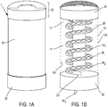
- the Figures 1A and 1B describe a first embodiment of a device 1 for dispensing a dose unit of an active substance in a solid dosage form.
- the Figures 1A and 1B describe more precisely and respectively external views ( Fig. 1A ) and internal ( Fig. 1B ) of such a device.
- the latter comprises a chamber 11 comprising a plurality of unit doses of an active substance in a solid dosage form.
- the chamber 11 is constituted, delimited or materialized by the inner wall 10i of an envelope 10.
- Such a chamber may be in a cylindrical form as indicated by the example described by FIG. Figure 1B .
- Doses M1, M2, Mi-corresponding in connection with the example described by the Figure 1B egg-shaped tablets - are present in the chamber 11.
- a control member In connection with the Figure 1B this organ is advantageously in the form of a cover or a handle 20.
- the control member triggers means for extracting a unit dose from the chamber 11.
- the dose M3 is thus delivered to the patient.
- a dispenser may comprise a receptacle 30 provided with a window so that a delivered unit dose is not expelled into the void at the risk of being soiled before use.
- such means for extracting and delivering may advantageously be in the form of a hollow tube 28 in the form of a circular helix intended to convey one or more unit doses.
- This tube is internal to the chamber 11, which comprises an orifice at its lower base, the lower distal portion of the opening tube 23 of said chamber through said orifice.
- Such a tube may be rotatably mounted along an axis substantially parallel to the axis of revolution of the chamber 11.
- the tube is further secured to the handle or lid. So, a action to create a partial or total revolution of said lid causes the flow of unit doses present in the chamber along the tube 28 which, like a guide, leads a unit dose - the dose M3 - to the orifice 13 of the chamber.
- Such a unit dose is thus extracted from the chamber 11 and delivered to the patient via the optional receptacle 30.
- the invention provides that the casing 10 of the device 1 can be arranged to encircle the chamber 11 irreversibly after initial filling thereof , thus prohibiting any new or second filling of the room.
- an envelope 10 may for example be thermoformed. It may, alternatively, result from the assembly of a plurality of elements that can be welded or glued mutually. Each element may comprise irreversible attachment means, of the clip type, for example, so that after an assembly step, the elements form a single assembly or confinement for unit doses.
- an envelope 10 may be provided with means which , during an attempted break-in, underline or attest the said attempt.
- the envelope 10 may, for example, comprise a network of guilloches printed or etched on the outer wall 10e.
- the envelope 10 may further have, by its arrangement or structure, areas of weakness or break initiation that, during a break-in of the envelope, accentuate automatically damage to the physical structure of the envelope.
- the envelope thus formed after its initial filling can be rigid, flexible or semi-rigid depending on the desired packaging, the operation of the envisaged device or even the requirements or local regulations.
- the envelope and, consequently, the chamber 11 can be substantially cylindrical, as described by Figures 1A and 1B .
- One and / or the other may alternatively have other geometric configurations: cone, solid polygonal section, half-moon section, etc.
- the chamber is directly delimited by the inner wall 10i of the envelope 10.
- the inner wall 10i of the envelope 10 may advantageously comprise one or more layers of protection, for example food varnishes. This ensures optimal neutrality of the inner envelope with respect to the contents of the chamber 11.
- the chamber 11 may consist of an insert.
- a shirt or cartridge or cassette - not shown in Figure 1B - May be pregnant by the envelope 10.
- the insert is previously filled with unit doses.
- This variant allows in particular to dissociate the step of constitution of a batch of unit doses - filling the insert - of the final packaging - assembly of a device according to the invention.
- This variant also makes it possible to dispense with any protection deposited on the inner wall of the envelope, in order to prevent any interaction between a material of the envelope and the unit doses. These are protected by the insert.
- the latter may advantageously also comprise moisture absorbing means 12 for capturing the ambient humidity and thus maintain a dry atmosphere within the chamber 11
- the upper part of the chamber 11 comprises a band of blotter or any other material capable of capturing or absorbing ambient humidity or even condensation within the chamber.
- Such means may, in addition or alternatively, be implanted at other locations within the device 1.
- a device according to the invention may further comprise means attesting the absence of any first distribution of a unit dose.
- such means may consist of a shutter means for delivering a unit dose, for example in the form of a lid, perfectly visible by the user of the device.
- a shutter can cooperate with the receptacle 30 thus obscuring the window of said receptacle. It can also cooperate with the envelope or constitute an extension or appendix of that envelope.
- the arrangement of said shutter is advantageously designed so that the eviction of the shutter is and remains discernible by the user.
- the eviction of the shutter can leave some damage on the envelope or on the receptacle so that, at the sole look of the user, the latter finds that the device has already made the object of first use.
- said means attesting the absence of any first distribution of a unit dose may consist of a mechanism or accessory provided for locking the actuator 20 actuated by the user, to control the distribution of a unit dose.
- such means may consist of a pellet or an adhesive tape, the eviction of which may advantageously, but not necessarily, leave some visible fragments on its support, or else a tab cooperating for example in conjunction with the lid or the handle 20 and the envelope or the body of the device.
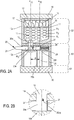
- the Figure 2A discloses a second embodiment of a device 1 according to the invention.
- a device comprises a chamber 11 for containing a plurality of unit doses M1 to Mi.
- the device 1 advantageously comprises two to three stages or modules.
- the upper stage E1 consists of a hollow cylinder whose lower base E1b is concave. It has an opening 13 - in the hollow of said lower base - whose geometry corresponds substantially to that of a unit dose.
- the lower base of the stage E1 is arranged so that said opening 13, or the vertex of the inverted cone of the base, is offset with respect to the axis of revolution a11 of the chamber formed by the inner wall of said floor.
- Unit doses may be arranged within the chamber 11 from the upper opening E1h of the stage E1. Once the chamber filled with unit doses, the upper part of the chamber 11 is closed by means of a lid 14. The latter cooperates with the upper part E1h irreversibly, by means of, for example, a connection by welding , collage, clips, etc.
- the chamber 11 constituted by the inner wall of the upper stage E1 has only one opening, the opening 13.
- the cover 14 may include means for absorbing ambient moisture, such as blotter, etc.
- the cover 14 may comprise a set of spiral wicks 15 or any other equivalent device, such as, for example, springs, elastic fibers, etc., of which the role consists in applying a sufficient pressure on the unit doses located in the upper part of the chamber 11. Gradually, the unit doses are leaning against each other and stop.
- a pressure disc 16 may advantageously be inserted between said spiral strands 15 and the unit doses, the disc whose underside, that is to say that intended to be in contact with the unit doses, has a neutral coating to prevent any direct contact spiral wicks 15 on unit doses.
- the pressure disc 16 may be integrally made of a coating or neutral material.
- the internal wall of the chamber 11 may comprise a protective varnish.
- the unit doses are directed naturally, by gravity and under the action of the spiral locks, towards the opening 13 of the chamber 11 when the device is kept substantially vertical.
- the device 1 has a second stage E2 whose function is to extract a unit dose from the plurality of unit doses present in the chamber 11 and to deliver this dose extracted in fine to a patient or more generally to a user of the device 1.
- stage E2 lower than stage E1 when device 1 is held in a substantially vertical position, comprises a delivery duct 25 substantially parallel to the axis of revolution a11 of chamber 11.
- the axis of revolution a25 of said duct 25 is also substantially parallel to the axis a13 perpendicular to the section of the opening 13.
- the axes a13 and a25 are offset so that the conduit 25 does not emerge in mirror from the opening 13.
- stage E2 is similar to a cylinder whose outer diameter is substantially identical to that of stage E1.
- the upper part of the stage E2 further comprises a housing 29 transverse and perpendicular to the axis of revolution of the stage E2.
- the housing 29 is further secant with the conduit 25, the latter opening into said housing 29.
- Such a housing 29 is blind and opens at one of its ends. It constitutes a slide in which a control member 20 can slide.
- the member 20 is advantageously similar to a cylinder full arranged to slide in said housing.
- the housing and the member 20 could have non-circular sections but mutually arranged so that the member can slide in the housing.
- the length of the control member 20 is sufficient for the distal portion 21 thereof to project.
- the member 20 may advantageously comprise a shoulder 20a so that the stroke thereof is limited in the housing 29, the shoulder abutting against the inner wall of the stage E2.
- the control member 20 can not be removed after assembly of the device 1.
- the housing 29 further comprises a spring or jack 26, cooperating with the inner wall of the stage E2 and the proximal portion (ie internal control) of the control member 20.
- the control member 20 is thus similar to a push button whose travel within the housing is limited by the shoulder 20a and the spring 26 resistance.
- control 20 advantageously has a solid structure with the exception of a through recess 20e whose section is close to that of the opening 13.
- the member 20 can thus convey a unit dose within the slide 29
- the through recess is arranged so that a single unit dose is extracted by gravity from the chamber 11 and received in said recess when the member 20 occupies its rest position (the spring 26 pushing said member until the shoulder 20a is in abutment cont re the inner wall of the stage E2) and when the device 1 is oriented so that the stage E1 is positioned above the stage E2.
- the control member When the control member is actuated by a user of the device 1, said member 20 enters the housing 29 and strips the spring 26.
- the through recess 20e carries the unit dose, which rests on the bottom wall of the housing 29.
- the recess 20e When the recess 20e is in mirror of the conduit 25, the unit dose is released and thus delivered by simple gravity.
- the opening 13 of the chamber 11 has been closed off by the body of the control member 20.
- the spring 26 pushes the latter to recover its rest position.
- the conduit 25 is closed by the body of the member 20.
- the opening 13 of the chamber is again facing the recess 20e and a unit dose can thus take place within the recess 20e.
- the height of the recess 20e is close to that of a unit dose.
- stages E1 and E2 advantageously comprise irreversible mutual fasteners.
- the lower part of the stage E1 and the upper part of the stage E2 are arranged to mutually cooperate irreversibly, by means of, for example, a connection by welding, gluing, clips, etc.
- the respective outer walls of the stages E1 and E2 as well as that of the top cover 14 constitute the casing 10 of the device 1. This thus encircles not only the chamber 11, but also the means for extracting and delivering a unit dose.
- the device 1 may comprise a receptacle 30.
- the receptacle 30 cooperates with the lower base of the stage E2 reversibly by means of, for example, a thread or adjustment allowing sufficient friction to hold the receptacle in place.
- a user can thus remove the receptacle 30, recover the unit dose and then reposition the receptacle 30 on the lower base of stage E2.
- the lower part of the duct 25 is closed again.
- the use of the receptacle makes it possible to add to the actuation of the organ a second operation necessary for the delivery of a unit dose.
- the invention provides that a complementary mechanism can be added to block / release the stroke of the control member 20.
- a complementary mechanism can be added to block / release the stroke of the control member 20.
- a mixed control meta-organ that requires two separate actions the user to extract a unit dose from the chamber 11 and deliver said unit dose to the user of the device 1.
- Such an arrangement allows to extract only a single unit dose by actuating the control member.
- the envelope of the device resulting from the assembly of the stages E1 and E2 or even the cover 14 can comprise any means, such as those described above in connection with a device 1 according to the Figures 1A and 1B , whose function is to emphasize an attempted break-in or increase the damage caused by such an attempt.
- a device may also include means attesting the absence of first distribution of a unit dose.
- such means may advantageously consist of a shutter means for delivering a unit dose.
- such a shutter may consist of a tab or an adhesive tape solidarisant, as long as it is not intentionally removed, the receptacle 30 and the lower base of the stage E2.
- such means attesting the absence of any first distribution of a unit dose may further consist of an accessory to constrain the controller 20 until said accessory is removed or altered.
- a device according to the invention may comprise means for preventing any "return" of a unit dose in the chamber 11.
- such means may consist of one or more flaps intended to close the opening 13 of the chamber 11 or again of the duct 25.
- the inner proximal wall of the recess 20e that is to say the wall closest to the end remaining internal to the housing 29 of the member 20, can cooperate with a flap 27.
- This operation can be performed by means of a pivot connection positioned in the upper part of the recess, whose length is substantially equal to the width of said recess 20e.
- a flap is naturally maintained pressed against the inner wall of the recess 20e when a unit dose previously present in the chamber 11 occupies the recess.
- the flap 27 remains pressed against the wall of the recess as long as the device is maintained in a substantially vertical position, that is to say when the stage E1 is positioned above the stage E2.
- the shutter 27 closes all or part of the opening 13. It completely closes the latter if the device is held vertically “upside down” that is to say when the stage E2 is positioned above the stage E1.
- the rotation of the flap 27 is limited by the presence of a slight abutment 27 ', present on the opposite inner wall within the recess 20e.
- Said abutment 27 ' is advantageously arranged so as not to impede the passage of a unit dose through the opening 13 and its reception within the 20e evident.
- This simple flap 27 makes it possible to prevent any attempt to fill the chamber 11 from the delivery duct 25. In order to attempt to carry out this operation, it is indeed necessary to turn the device, the distal portion 25b of the delivery duct 25 upwards. inserting a "fraudulent" dose in said conduit 25, to actuate the control member 20 so that the recess 20e faces the conduit 25 and thus deposit said dose within the recess 20e. By releasing the member 20, the recess is positioned at the opening 13 of the chamber 11. The flap 27 remains positioned between the injected unit dose and the opening 13. It can not penetrate the chamber.
- the latter may comprise means for absorbing moisture and / or condensation, not shown in FIG. Figure 2A .
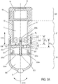
- the figure 3A discloses a third embodiment of a device for dispensing a unit dose according to the invention.
- a first stage E1 substantially cylindrical and hollow, contains a chamber 11 intended to accommodate unit doses M1, M2, Mi.
- the cylinder E1 is closed at its lower base 11b.
- Said base comprises an opening 13 whose configuration substantially corresponds to the dimensions of a unit dose.
- the thickness of the cylindrical wall of the stage E1 is tapered at its lower part over a height E1b, so that the stage E1 can be inserted into the upper part of a lower stage E2 described below.
- the upper part of the stage E1 can be closed by means of a cover or, as we shall see later, by an upper stage E0.
- Said cover or the lower part of said optional upper stage E0 cooperates with the upper part of the stage E1, and is sealed thereto in a permanent and irreversible connection, by means of a connection by welding, gluing, clips, etc.
- the chamber 11 is thus delimited by the inner wall of the stage E1.
- This inner wall may advantageously comprise a layer of food varnish or any other protective layer in order to avoid an interaction between the unit doses and a constituent material E1.
- the inner wall of the chamber 11 may further comprise one or more bands of moisture-absorbing or condensing materials 12 for drying out the atmosphere prevailing within the chamber 11.
- the stage E2, lower than the stage E1, consists of a hollow cylinder whose outer diameter is substantially identical to that of the upper part of the stage E1.
- the thickness of the cylindrical wall of the upper part of the stage E2 is reduced to a height E2h substantially equal to the height E1b previously described.
- the two stages E1 and E2 can thus cooperate, the lower part of E1 sliding in the upper part of E2 over a distance substantially equal respectively to the heights E1b and / or E2h.
- An inner shoulder of the upper part of the stage E2 serves to crimp a spring 209 inserted between the inner wall of E2 and the outer wall of E1. This spring 209 exerts a force F tending to repel the two stages mutually.
- the stage E2 further comprises an internal structure, for example a star having four arms 204a, 204b, 204c, 204d substantially orthogonal to the axis of revolution of the stage E2.
- the invention can not be limited to the number of said arms or the configuration of the present structure.
- Said arms join substantially at a point intersecting with the axis of revolution of the stage E2.
- Said junction of the arms further cooperates in a fixed connection with a torsion shaft 203, the axis of revolution substantially coincides with that of the E2 stage.
- the length of said shaft is such that the latter can lead, through an opening, within the chamber 11 of the stage E1 after assembly of the two stages.
- Each arm 204a to 204d has a prominent lug in a direction close to that of the torsion shaft 203.
- the invention provides that a disc 201, having an opening 213 similar to the opening 13 of the chamber 11, is rotatably mounted on the torsion shaft 203.
- the disc 201 is positioned on the shaft 203 to be applied substantially against the outer wall of the lower base 11b of the stage E1.
- a helical spring 207 encircling the shaft 203 keeps the disk 201 substantially pressed against the lower base of the stage E1, the disk 201 sliding along the torsion shaft 203.
- the underside of said disk 201, c ' that is to say the face opposite to that facing element E1, has as many recesses 202 (in our example four) that there are arms at the star structure of the stage E2.
- Each recess 202 is arranged to accommodate the distal portion of one of the pins or protuberances 205a to 205d, the length of said pins being, in turn, determined so that the cooperation between the distal portions thereof and the recesses 202 do not occurs only when the spring 209 is crushed.
- the respective ends of said spring 207 are integral on the one hand with the disk 201 and on the other hand with the base of the torsion shaft 203 to maintain the recesses 202 aligned with respect to the protuberances 205a to 205d.
- the distal portion of the shaft 203 - after assembly - is fixed to the lower part of the chamber 11, for example by means of one or more longitudinal pins or protruding grooves 206 on the distal portion of the shaft 203, cooperating with a suitable opening made in the lower base of the stage E1.
- Such an arrangement E1-E2 allows a first movement MVT1 of the "slide" type of the lower part of the stage E1 within the upper part of the stage E2.
- the shaft 203 serves as a guide. It further limits the travel of the stage E1 by means of a stop 206b positioned at the end of the shaft 203 opening into the chamber 11.
- the arrangement E1-E2 furthermore allows a second rotary type movement MVT2 of the stage E2 with respect to the stage E1.
- the torsion shaft 203 indeed allows this movement MVT2 under the action for example of a user.
- the torsion shaft 203 automatically returns the stages E1 and E2 in relative positions of rest thanks to the spring function exerted by the tree as soon as the user releases his effort.
- the opening 213 of the disc 201 is similar to the opening 13 of the chamber 11. It is advantageously positioned at a distance, or radius, with respect to the shaft 203, substantially equal to that separating the opening 13 of said shaft.
- the disk 201 is positioned initially, that is to say when the stages E1 and E2 occupy their relative positions of rest, so that the two openings 13 and 213 face each other only when the torsion shaft reaches maximum torsion and when the disc 201 is blocked by the lugs 204a to 205d, the latter having penetrated the recesses 202 under the effect of a sufficient thrust to crush the spring 209.
- a unit dose can not be extracted from the chamber 11 and delivered only if the two movements MVT1 and MVT2 are conjugated.
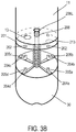
- This arrangement thus provides a response to the risk of young children using the unit dose dispenser unattended. Indeed, two separate operations are necessary to trigger the delivery of a unit dose. This is extracted and delivered by gravity, said unit dose leaving the chamber 11 via the opening 13, passing through the opening 213 temporarily aligned with the opening 13 and falling through the arms 205a to 205d in the lower part 300 of the stage E2, all provided that the device is held substantially vertical, the stage E1 being positioned above the stage E2.
- the control member - in the sense of the invention - thus consists in associating the two stages E1 and E2 operable with respect to one another by a user of the device 1.
- the stage E2 can be opened at its lower base 300. It can alternatively have a conical shape, or dome, inverted to form a receptacle for receiving a unit dose extracted. In order to be able to use said unit dose, a user can remove a plug 31 intended to close an opening made in the lower part of the element E2.
- the lower part of E2 can furthermore include means for absorbing moisture, or even condensation, in the receptacle 300.
- the assembly of the elements E1 and E2 can be made irreversible, firstly by the installation or machining of the abutment 206b, positioned on the distal portion of the shaft 203 and, by closing the upper part of the the chamber 11, after filling thereof by means of the lid or the upper stage and optional E0.
- the device described in connection with the Figures 3A and 3B generally presents a cylindrical configuration. It could alternatively comprise stages having polygonal or other sections.
- a device according to the invention further comprises means for timestamping and recording each delivery of a unit dose. It may also include electronic means for identifying the device or the active substance (s) comprising the unit doses contained in the chamber. To host such electronic means, device according to the invention may include a dedicated housing for this purpose.
- a stage E0 for accommodating or containing, within a housing 51, a processing unit cooperating with the control member and with a source delivering the electrical energy necessary for the operation of said processing unit.
- a source may be a battery in said housing 51 or a photovoltaic cell 52 cooperating with said processing unit.
- a processing unit (not shown in figure 3A ) advantageously comprises a clock and a memory for respectively timestamp and record each actuation of the control member triggering the means for extracting and delivering a unit dose.
- the stage E1 may comprise a stop cooperating with the lower stage to limit the twisting of the shaft 203.
- the processing unit can exploit this contact as information delivered by the control member, constituted by the association of the two stages E1 and E2, attesting a delivery of a unit dose.
- the processing unit can implement any protocol to relay this information. For example, if the stages E1 and E2 consist of electrically conductive materials, bringing the two stages into contact via the abutment may constitute a grounding, or electrical reference, detectable by the unit of electricity. treatment.
- a device 1 may comprise a limit switch detecting the thrust exerted by a user on the member 20.
- a sensor may be positioned in the housing 29. As soon as said sensor is biased by the proximal portion of the member 20, c that is, when the user has pushed said member 20 within the housing 29, said end-of-travel sensor transmits the delivery information to the processing unit.
- the means for extracting and delivering a unit dose may include a sensor for detecting the delivery of a unit dose as such.
- a sensor for detecting the delivery of a unit dose may be positioned on the disk 201 near the opening 213.
- the processing unit cooperates more directly with the control member but with said sensor which transmits information as soon as a unit dose passes through the opening 213.
- the processing unit can time stamp and record each delivery of a unit dose.
- the invention provides that the casing of a device according to the invention can advantageously encase the chamber 11 and said housing 51.
- the stages E1 and E0 can be sealed, that is to say cooperate in a fixed and irreversible connection, for example by means of a weld, clips, gluing, etc.
- This envelope is materialized by the outer walls of the two floors E0 and E1. Choosing the stage E0 to style and thus close the chamber 11 makes it possible not to have to resort to a dedicated cover.
- Said envelope resulting from the assembly of the stages E1 and E0 may comprise any means capable of attesting to or even aggravating an attempted break-in as mentioned above in connection with the previous embodiments described in relation to the Figures 1A and 2A .
- the housing 51 may advantageously comprise a non-conductive resin or foam to preserve the electronic elements from any moisture or condensation within said housing.
- said processing unit may advantageously comprise a wireless communication interface for communicating with the outside world.
- the processing unit may comprise a wired communication interface for communicating with the outside world.
- communication can be established with a reader or a terminal to collect, process or restore, using a suitable human-machine interface, information stored or processed by the processing unit.
- the reader or terminal is thus able to implement a communication protocol with the processing unit of the device.
- first and second identifiers respectively dedicated to the device and to an operator, such as a laboratory pharmaceutical or any subcontractor carrying out the packaging of drug unit doses, for example, having initially filled the chamber or else an identifier characterizing an active substance in solid dosage form contained in the chamber.
- a device may comprise a clean human-machine interface and able to restore information stored in the memory or developed by the processing unit, the latter controlling said man-machine interface.
- the device 1 described in connection with the figure 3A may include a flexible screen 53 type LCD for example.
- the processing unit may for example, in response to a request from the user, by means of a dedicated command button, or after a predetermined number of unit dose deliveries, implement a hash function or reversible compression.
- a human can collect information stored or produced by the processing unit, for example in connection with the history of unit dose deliveries.
- the user reads a short alphanumeric sentence, of four to sixteen characters preferably to limit the effort of the user and the risk of poor reproduction, by consulting the man-machine interface 53 of the device.
- the user can then communicate this sentence to an interlocutor by phone, fax, email, etc.
- the human-machine interface may consist further or alternatively in a loudspeaker or more generally include any means allowing a human to perceive information.
- the invention provides that any communication with the processing unit can be protected by conventional techniques, such as encryption and / or signature and / or authentication, etc.
- said memory can be advantageously non-erasable.
- the invention furthermore relates to a method implemented by the processing unit of a device according to the invention.
- a method comprises in particular a step for timestamping each unit dose extracted from the chamber and thus delivered.
- the processing unit cooperates with the control member triggering a delivery of a unit dose or with a sensor detecting such a delivery.
- the presence of a clock within the processing unit allows it to date a delivery.
- Any time stamping technique can be implemented: for example, from a GMT repository or any other reference from which, the processing unit increments a counter of time units.
- the processing unit can further implement a method comprising a step for encoding and restoring to the outside world information produced from the contents of the memory of the processing unit, for example the history of the deliveries.
- the initialization or programming of the processing unit can be advantageously performed by means of a computer program comprising one or more program instructions which, when they are interpreted or executed by the processing unit, cause the implementation of a method as mentioned above.
- a program can be downloaded or implanted in a memory cooperating with the processing unit at the time of assembly of the device or during the customization process of the latter.
Landscapes
- Engineering & Computer Science (AREA)
- Mechanical Engineering (AREA)
- Food Science & Technology (AREA)
- Medical Preparation Storing Or Oral Administration Devices (AREA)
- Infusion, Injection, And Reservoir Apparatuses (AREA)
Applications Claiming Priority (2)
| Application Number | Priority Date | Filing Date | Title |
|---|---|---|---|
| FR1356651A FR3007969B1 (fr) | 2013-07-05 | 2013-07-05 | Distributeur d'une dose unitaire d'une substance active sous une forme galenique solide |
| PCT/FR2014/051705 WO2015001262A1 (fr) | 2013-07-05 | 2014-07-03 | Distributeur d'une dose unitaire d'une substance active sous une forme galenique solide |
Publications (2)
| Publication Number | Publication Date |
|---|---|
| EP3016867A1 EP3016867A1 (fr) | 2016-05-11 |
| EP3016867B1 true EP3016867B1 (fr) | 2018-04-04 |
Family
ID=49667297
Family Applications (1)
| Application Number | Title | Priority Date | Filing Date |
|---|---|---|---|
| EP14747078.5A Active EP3016867B1 (fr) | 2013-07-05 | 2014-07-03 | Distributeur d'une dose unitaire d'une substance active sous une forme galenique solide |
Country Status (8)
Cited By (1)
| Publication number | Priority date | Publication date | Assignee | Title |
|---|---|---|---|---|
| WO2020009716A1 (en) * | 2018-07-06 | 2020-01-09 | Gemc2, Llc | Gem applicator assembly |
Families Citing this family (21)
| Publication number | Priority date | Publication date | Assignee | Title |
|---|---|---|---|---|
| FR3007969B1 (fr) * | 2013-07-05 | 2016-01-29 | Medicodose Systems | Distributeur d'une dose unitaire d'une substance active sous une forme galenique solide |
| FR3017377B1 (fr) * | 2014-02-12 | 2017-01-13 | Stiplastics | Dispositif de comptage et de distribution d'objets |
| US10596071B1 (en) * | 2015-09-22 | 2020-03-24 | Michael Song | Locked pill bottle with timed dispense limits |
| US11246805B2 (en) | 2016-08-26 | 2022-02-15 | Changhai Chen | Dispenser system and methods for medication compliance |
| US10722431B2 (en) | 2016-08-26 | 2020-07-28 | Changhai Chen | Dispenser system and methods for medication compliance |
| US20180055738A1 (en) | 2016-08-26 | 2018-03-01 | Changhai Chen | Dispenser system and methods for medication compliance |
| WO2018130664A1 (en) * | 2017-01-13 | 2018-07-19 | Philip Morris Products S.A. | Dispensing device |
| US10683160B2 (en) * | 2017-02-15 | 2020-06-16 | Nypro Inc. | Apparatus, system and method for a pill dispenser |
| FR3070039B1 (fr) * | 2017-08-09 | 2019-08-30 | Chanel Parfums Beaute | Dispositif de distribution d'un produit se presentant sous forme de billes |
| EP3672559B1 (en) * | 2017-08-25 | 2022-03-09 | Barbosa de Abreu e Sousa, Armando Miguel | Medicament dispenser |
| CN107826445B (zh) * | 2017-11-12 | 2019-07-16 | 安徽益顺塑业有限公司 | 一种药瓶 |
| CN109157417B (zh) * | 2018-09-30 | 2024-05-14 | 北京翰林航宇科技发展股份公司 | 一种装量调节装置 |
| US20200130921A1 (en) * | 2018-10-26 | 2020-04-30 | Serv Goyal | Bag container system |
| US11154460B2 (en) * | 2018-12-10 | 2021-10-26 | International Business Machines Corporation | Personal prescription dispenser |
| EP3674233A1 (en) * | 2018-12-27 | 2020-07-01 | Clariant Plastics & Coatings Ltd | A tablet dispensing device |
| US11267643B2 (en) * | 2019-01-22 | 2022-03-08 | Coopervision International Limited | Contact lens dispenser |
| CN109573353B (zh) * | 2019-01-29 | 2024-02-20 | 王伟 | 一种汽车维修用螺帽存储与取用装置 |
| EP3692844A1 (en) * | 2019-02-07 | 2020-08-12 | Nerudia Limited | Smoking substitute apparatus |
| CN111573017B (zh) * | 2020-05-08 | 2022-01-28 | 安阳工学院 | 一种智能助老服药器 |
| CN113071815A (zh) * | 2021-03-26 | 2021-07-06 | 张交腾 | 一种心血管内科用硝酸甘油避光储药瓶 |
| US11707163B2 (en) * | 2021-06-14 | 2023-07-25 | Angelo Masino | Dispensers and related devices and methods for mounting dispensers |
Family Cites Families (34)
| Publication number | Priority date | Publication date | Assignee | Title |
|---|---|---|---|---|
| US3785525A (en) * | 1972-01-31 | 1974-01-15 | Safe Well Mfg Co | Chemical tablet dispensing device for wells |
| US3889847A (en) * | 1973-11-01 | 1975-06-17 | Afa Corp | Child-resistant pill dispenser |
| US3927484A (en) * | 1974-02-04 | 1975-12-23 | Gilbreth Co | Die-cut coupon shrink label |
| MX146241A (es) * | 1976-09-30 | 1982-06-02 | Antonio Lorca Vera | Mejoras a envase para suministrar pastillas y similares |
| US4150766A (en) * | 1977-03-18 | 1979-04-24 | Knorr Robert H | Dispensing apparatus |
| US4273254A (en) * | 1979-01-23 | 1981-06-16 | Brian Cuppleditch | Device for containing and dispensing particles such as tablets |
| NL8200666A (nl) * | 1982-02-19 | 1983-09-16 | Philips Nv | Transmissieschakeling voor een elektronisch telefoontoestel. |
| US4560086A (en) * | 1983-09-21 | 1985-12-24 | Israel Stol | Helical elevating dispenser for round objects such as candies |
| US4611727A (en) * | 1985-02-20 | 1986-09-16 | Graff James C | Solid oral dosage dispenser with safety, tamper-proof and sanitation features |
| US4782980A (en) * | 1987-01-05 | 1988-11-08 | Himedics, Inc. | Capsule dispenser |
| US5176290A (en) * | 1991-10-17 | 1993-01-05 | Machine-O-Matic Limited | Coin operated vending machine |
| US5269413A (en) * | 1992-09-04 | 1993-12-14 | George Stern | Container for pills |
| US5476181A (en) * | 1994-03-15 | 1995-12-19 | Seidler; David | Child-resistant product dispenser |
| US5833117A (en) * | 1996-04-15 | 1998-11-10 | Parkway Machine Corporation | Dynamic vending machine with track insert assembly |
| FR2758536B1 (fr) | 1997-01-21 | 2001-01-26 | Velfor Plast Sa | Emballage distributeur d'articles et produits stockes |
| DE19737747A1 (de) * | 1997-08-29 | 1998-02-05 | Schulz Rolf A Dipl Kaufm | Fallschacht - Tablettenspender |
| US6729330B2 (en) * | 1998-05-05 | 2004-05-04 | Trudell Medical International | Indicating device for aerosol container |
| GB0216831D0 (en) * | 2002-07-19 | 2002-08-28 | Glaxo Group Ltd | Medicament dispenser |
| CA2405361A1 (en) * | 2002-09-26 | 2004-03-26 | Beaver Machine Corporation | Bulk vending machine |
| GB0328859D0 (en) * | 2003-12-12 | 2004-01-14 | Clinical Designs Ltd | Dispenser and counter |
| US7175046B2 (en) * | 2004-06-21 | 2007-02-13 | Shen-Hao Yao | Merchandise output device of a vending machine |
| US8357114B2 (en) * | 2006-01-06 | 2013-01-22 | Acelrx Pharmaceuticals, Inc. | Drug dispensing device with flexible push rod |
| CN106727271B (zh) * | 2006-01-06 | 2020-02-14 | 阿塞尔Rx制药有限公司 | 小体积口腔经粘膜剂型 |
| CN201002842Y (zh) * | 2007-01-12 | 2008-01-09 | 黄杏水 | 圆形螺旋滑梯糖果盒 |
| DE202007018407U1 (de) * | 2007-03-16 | 2008-07-10 | Pöppelmann Holding GmbH & Co. KG | Spender |
| CN101711149B (zh) * | 2007-04-11 | 2014-05-28 | 梅迪克潘公司 | 药片分配器系统 |
| EP2289480A3 (en) * | 2007-12-21 | 2011-10-19 | DSM IP Assets B.V. | Locking element for dispenser |
| JP5240573B2 (ja) * | 2008-04-24 | 2013-07-17 | 敏雄 博多 | 錠剤用緩衝材 |
| JP5676755B2 (ja) * | 2010-06-08 | 2015-02-25 | シーエスピー テクノロジーズ,インコーポレイティド | 錠剤ディスペンサー |
| CN202072133U (zh) * | 2011-05-14 | 2011-12-14 | 林旭捷 | 一种定片倒出药片瓶 |
| CN202244708U (zh) * | 2011-09-19 | 2012-05-30 | 林旭捷 | 一种药片定量装置 |
| CN202777062U (zh) * | 2012-09-19 | 2013-03-13 | 王兴林 | 一种自动出药片/粒的药瓶 |
| DE202012009997U1 (de) * | 2012-10-19 | 2012-11-23 | Petra Claudia Bopp | Futterspender und Tragvorrichtung |
| FR3007969B1 (fr) * | 2013-07-05 | 2016-01-29 | Medicodose Systems | Distributeur d'une dose unitaire d'une substance active sous une forme galenique solide |
-
2013
- 2013-07-05 FR FR1356651A patent/FR3007969B1/fr active Active
-
2014
- 2014-07-03 JP JP2016522719A patent/JP2016526427A/ja active Pending
- 2014-07-03 CN CN201480046378.3A patent/CN105473458B/zh not_active Expired - Fee Related
- 2014-07-03 CA CA2916837A patent/CA2916837A1/en not_active Abandoned
- 2014-07-03 US US14/902,413 patent/US9975688B2/en not_active Expired - Fee Related
- 2014-07-03 HK HK16105227.6A patent/HK1218106A1/zh unknown
- 2014-07-03 EP EP14747078.5A patent/EP3016867B1/fr active Active
- 2014-07-03 WO PCT/FR2014/051705 patent/WO2015001262A1/fr active Application Filing
Cited By (1)
| Publication number | Priority date | Publication date | Assignee | Title |
|---|---|---|---|---|
| WO2020009716A1 (en) * | 2018-07-06 | 2020-01-09 | Gemc2, Llc | Gem applicator assembly |
Also Published As
| Publication number | Publication date |
|---|---|
| FR3007969A1 (fr) | 2015-01-09 |
| JP2016526427A (ja) | 2016-09-05 |
| US20160207691A1 (en) | 2016-07-21 |
| HK1218106A1 (zh) | 2017-02-03 |
| US9975688B2 (en) | 2018-05-22 |
| EP3016867A1 (fr) | 2016-05-11 |
| FR3007969B1 (fr) | 2016-01-29 |
| CN105473458B (zh) | 2018-05-22 |
| WO2015001262A1 (fr) | 2015-01-08 |
| CN105473458A (zh) | 2016-04-06 |
| CA2916837A1 (en) | 2015-01-08 |
Similar Documents
| Publication | Publication Date | Title |
|---|---|---|
| EP3016867B1 (fr) | Distributeur d'une dose unitaire d'une substance active sous une forme galenique solide | |
| EP2579932B1 (fr) | Dispositif de distribution de produit fluide | |
| EP3213264B1 (fr) | Procédé d'authentification de l'ensemble de fermeture d'un récipient | |
| EP1140656A1 (fr) | Distributeur d'objets | |
| EP0850082B1 (fr) | Dispositif de pre-dosage de produit pulverulent pour un distributeur de produit | |
| FR2585563A1 (fr) | Dispositif pour administrer des medicaments a des patients | |
| EP2182908A2 (fr) | Dispositif de conditionnement et d'administration sub-linguale de principes actifs | |
| CA2626276A1 (fr) | Emballage securise pour comprime | |
| EP3452001A1 (fr) | Dispositif et procédé d'emballage de médicaments solides, dispositif de stockage et de distribution de tels médicaments et procédé de distribution | |
| EP2370140B1 (fr) | Dispositif de conditionnement et d'administration de principes actifs en solution hydro-alcoolique | |
| WO2019092356A1 (fr) | Dispositif chargeur/répartiteur d'objets dans un réservoir de stockage de tels objets, utilisations d'un tel dispositif et procédé de chargement et de répartition | |
| EP3648729B1 (fr) | Cassette de stockage et de distribution de produits non gazeux et procédé de fabrication | |
| EP3651840B1 (fr) | Dispositif de distribution de produit fluide | |
| EP3801436B1 (fr) | Etui pour medicaments | |
| WO2015091597A1 (fr) | Dispositif d'obturation d'un recipient presentant un col | |
| FR2991186A1 (fr) | Dispositif de distribution de produit fluide. | |
| EP1398277A1 (fr) | Blister sécurisé à usage pharmaceutique, plaquette et procédé de fabrication correspondants | |
| FR2748001A1 (fr) | Dispositif distributeur de granules | |
| FR2608136A1 (fr) | Emballage distributeur de granules notamment de granules homeopathiques | |
| WO2021122852A1 (fr) | Distributeur automatique de produits fluides contenus dans des cartouches munie d'une enveloppe sécurisée et d'un réservoir à pompe doseuse | |
| WO2018002535A1 (fr) | Dispositif d'administration d'au moins un principe actif par voie per-muqueuse buccale | |
| FR2694272A1 (fr) | Pilullier. | |
| FR3031086A1 (fr) | Dispositif pour recuperer de maniere securisee des comprimes contenus dans une alveole d'un pilulier fermee par une membrane apte a etre perforee. | |
| FR3059895A1 (fr) | Dispositif d'administration d'au moins un principe actif par voie per-muqueuse buccale. |
Legal Events
| Date | Code | Title | Description |
|---|---|---|---|
| PUAI | Public reference made under article 153(3) epc to a published international application that has entered the european phase |
Free format text: ORIGINAL CODE: 0009012 |
|
| 17P | Request for examination filed |
Effective date: 20151211 |
|
| AK | Designated contracting states |
Kind code of ref document: A1 Designated state(s): AL AT BE BG CH CY CZ DE DK EE ES FI FR GB GR HR HU IE IS IT LI LT LU LV MC MK MT NL NO PL PT RO RS SE SI SK SM TR |
|
| AX | Request for extension of the european patent |
Extension state: BA ME |
|
| DAX | Request for extension of the european patent (deleted) | ||
| RAP1 | Party data changed (applicant data changed or rights of an application transferred) |
Owner name: MEDICODOSE SYSTEMS |
|
| STAA | Information on the status of an ep patent application or granted ep patent |
Free format text: STATUS: EXAMINATION IS IN PROGRESS |
|
| 17Q | First examination report despatched |
Effective date: 20170331 |
|
| GRAP | Despatch of communication of intention to grant a patent |
Free format text: ORIGINAL CODE: EPIDOSNIGR1 |
|
| STAA | Information on the status of an ep patent application or granted ep patent |
Free format text: STATUS: GRANT OF PATENT IS INTENDED |
|
| INTG | Intention to grant announced |
Effective date: 20171107 |
|
| GRAS | Grant fee paid |
Free format text: ORIGINAL CODE: EPIDOSNIGR3 |
|
| GRAA | (expected) grant |
Free format text: ORIGINAL CODE: 0009210 |
|
| STAA | Information on the status of an ep patent application or granted ep patent |
Free format text: STATUS: THE PATENT HAS BEEN GRANTED |
|
| AK | Designated contracting states |
Kind code of ref document: B1 Designated state(s): AL AT BE BG CH CY CZ DE DK EE ES FI FR GB GR HR HU IE IS IT LI LT LU LV MC MK MT NL NO PL PT RO RS SE SI SK SM TR |
|
| REG | Reference to a national code |
Ref country code: GB Ref legal event code: FG4D Free format text: NOT ENGLISH |
|
| REG | Reference to a national code |
Ref country code: CH Ref legal event code: EP |
|
| REG | Reference to a national code |
Ref country code: AT Ref legal event code: REF Ref document number: 985343 Country of ref document: AT Kind code of ref document: T Effective date: 20180415 |
|
| REG | Reference to a national code |
Ref country code: DE Ref legal event code: R096 Ref document number: 602014023357 Country of ref document: DE |
|
| REG | Reference to a national code |
Ref country code: IE Ref legal event code: FG4D Free format text: LANGUAGE OF EP DOCUMENT: FRENCH |
|
| REG | Reference to a national code |
Ref country code: FR Ref legal event code: PLFP Year of fee payment: 5 |
|
| REG | Reference to a national code |
Ref country code: NL Ref legal event code: MP Effective date: 20180404 |
|
| REG | Reference to a national code |
Ref country code: LT Ref legal event code: MG4D |
|
| PG25 | Lapsed in a contracting state [announced via postgrant information from national office to epo] |
Ref country code: NL Free format text: LAPSE BECAUSE OF FAILURE TO SUBMIT A TRANSLATION OF THE DESCRIPTION OR TO PAY THE FEE WITHIN THE PRESCRIBED TIME-LIMIT Effective date: 20180404 |
|
| PG25 | Lapsed in a contracting state [announced via postgrant information from national office to epo] |
Ref country code: SE Free format text: LAPSE BECAUSE OF FAILURE TO SUBMIT A TRANSLATION OF THE DESCRIPTION OR TO PAY THE FEE WITHIN THE PRESCRIBED TIME-LIMIT Effective date: 20180404 Ref country code: ES Free format text: LAPSE BECAUSE OF FAILURE TO SUBMIT A TRANSLATION OF THE DESCRIPTION OR TO PAY THE FEE WITHIN THE PRESCRIBED TIME-LIMIT Effective date: 20180404 Ref country code: PL Free format text: LAPSE BECAUSE OF FAILURE TO SUBMIT A TRANSLATION OF THE DESCRIPTION OR TO PAY THE FEE WITHIN THE PRESCRIBED TIME-LIMIT Effective date: 20180404 Ref country code: LT Free format text: LAPSE BECAUSE OF FAILURE TO SUBMIT A TRANSLATION OF THE DESCRIPTION OR TO PAY THE FEE WITHIN THE PRESCRIBED TIME-LIMIT Effective date: 20180404 Ref country code: BG Free format text: LAPSE BECAUSE OF FAILURE TO SUBMIT A TRANSLATION OF THE DESCRIPTION OR TO PAY THE FEE WITHIN THE PRESCRIBED TIME-LIMIT Effective date: 20180704 Ref country code: FI Free format text: LAPSE BECAUSE OF FAILURE TO SUBMIT A TRANSLATION OF THE DESCRIPTION OR TO PAY THE FEE WITHIN THE PRESCRIBED TIME-LIMIT Effective date: 20180404 Ref country code: NO Free format text: LAPSE BECAUSE OF FAILURE TO SUBMIT A TRANSLATION OF THE DESCRIPTION OR TO PAY THE FEE WITHIN THE PRESCRIBED TIME-LIMIT Effective date: 20180704 Ref country code: AL Free format text: LAPSE BECAUSE OF FAILURE TO SUBMIT A TRANSLATION OF THE DESCRIPTION OR TO PAY THE FEE WITHIN THE PRESCRIBED TIME-LIMIT Effective date: 20180404 |
|
| PG25 | Lapsed in a contracting state [announced via postgrant information from national office to epo] |
Ref country code: GR Free format text: LAPSE BECAUSE OF FAILURE TO SUBMIT A TRANSLATION OF THE DESCRIPTION OR TO PAY THE FEE WITHIN THE PRESCRIBED TIME-LIMIT Effective date: 20180705 Ref country code: LV Free format text: LAPSE BECAUSE OF FAILURE TO SUBMIT A TRANSLATION OF THE DESCRIPTION OR TO PAY THE FEE WITHIN THE PRESCRIBED TIME-LIMIT Effective date: 20180404 Ref country code: RS Free format text: LAPSE BECAUSE OF FAILURE TO SUBMIT A TRANSLATION OF THE DESCRIPTION OR TO PAY THE FEE WITHIN THE PRESCRIBED TIME-LIMIT Effective date: 20180404 Ref country code: HR Free format text: LAPSE BECAUSE OF FAILURE TO SUBMIT A TRANSLATION OF THE DESCRIPTION OR TO PAY THE FEE WITHIN THE PRESCRIBED TIME-LIMIT Effective date: 20180404 |
|
| REG | Reference to a national code |
Ref country code: AT Ref legal event code: MK05 Ref document number: 985343 Country of ref document: AT Kind code of ref document: T Effective date: 20180404 |
|
| PG25 | Lapsed in a contracting state [announced via postgrant information from national office to epo] |
Ref country code: PT Free format text: LAPSE BECAUSE OF FAILURE TO SUBMIT A TRANSLATION OF THE DESCRIPTION OR TO PAY THE FEE WITHIN THE PRESCRIBED TIME-LIMIT Effective date: 20180806 |
|
| REG | Reference to a national code |
Ref country code: DE Ref legal event code: R097 Ref document number: 602014023357 Country of ref document: DE |
|
| PG25 | Lapsed in a contracting state [announced via postgrant information from national office to epo] |
Ref country code: CZ Free format text: LAPSE BECAUSE OF FAILURE TO SUBMIT A TRANSLATION OF THE DESCRIPTION OR TO PAY THE FEE WITHIN THE PRESCRIBED TIME-LIMIT Effective date: 20180404 Ref country code: SK Free format text: LAPSE BECAUSE OF FAILURE TO SUBMIT A TRANSLATION OF THE DESCRIPTION OR TO PAY THE FEE WITHIN THE PRESCRIBED TIME-LIMIT Effective date: 20180404 Ref country code: AT Free format text: LAPSE BECAUSE OF FAILURE TO SUBMIT A TRANSLATION OF THE DESCRIPTION OR TO PAY THE FEE WITHIN THE PRESCRIBED TIME-LIMIT Effective date: 20180404 Ref country code: RO Free format text: LAPSE BECAUSE OF FAILURE TO SUBMIT A TRANSLATION OF THE DESCRIPTION OR TO PAY THE FEE WITHIN THE PRESCRIBED TIME-LIMIT Effective date: 20180404 Ref country code: DK Free format text: LAPSE BECAUSE OF FAILURE TO SUBMIT A TRANSLATION OF THE DESCRIPTION OR TO PAY THE FEE WITHIN THE PRESCRIBED TIME-LIMIT Effective date: 20180404 Ref country code: EE Free format text: LAPSE BECAUSE OF FAILURE TO SUBMIT A TRANSLATION OF THE DESCRIPTION OR TO PAY THE FEE WITHIN THE PRESCRIBED TIME-LIMIT Effective date: 20180404 |
|
| PLBE | No opposition filed within time limit |
Free format text: ORIGINAL CODE: 0009261 |
|
| STAA | Information on the status of an ep patent application or granted ep patent |
Free format text: STATUS: NO OPPOSITION FILED WITHIN TIME LIMIT |
|
| PG25 | Lapsed in a contracting state [announced via postgrant information from national office to epo] |
Ref country code: SM Free format text: LAPSE BECAUSE OF FAILURE TO SUBMIT A TRANSLATION OF THE DESCRIPTION OR TO PAY THE FEE WITHIN THE PRESCRIBED TIME-LIMIT Effective date: 20180404 Ref country code: IT Free format text: LAPSE BECAUSE OF FAILURE TO SUBMIT A TRANSLATION OF THE DESCRIPTION OR TO PAY THE FEE WITHIN THE PRESCRIBED TIME-LIMIT Effective date: 20180404 |
|
| 26N | No opposition filed |
Effective date: 20190107 |
|
| PG25 | Lapsed in a contracting state [announced via postgrant information from national office to epo] |
Ref country code: MC Free format text: LAPSE BECAUSE OF FAILURE TO SUBMIT A TRANSLATION OF THE DESCRIPTION OR TO PAY THE FEE WITHIN THE PRESCRIBED TIME-LIMIT Effective date: 20180404 Ref country code: LU Free format text: LAPSE BECAUSE OF NON-PAYMENT OF DUE FEES Effective date: 20180703 |
|
| PG25 | Lapsed in a contracting state [announced via postgrant information from national office to epo] |
Ref country code: SI Free format text: LAPSE BECAUSE OF FAILURE TO SUBMIT A TRANSLATION OF THE DESCRIPTION OR TO PAY THE FEE WITHIN THE PRESCRIBED TIME-LIMIT Effective date: 20180404 |
|
| PG25 | Lapsed in a contracting state [announced via postgrant information from national office to epo] |
Ref country code: MT Free format text: LAPSE BECAUSE OF FAILURE TO SUBMIT A TRANSLATION OF THE DESCRIPTION OR TO PAY THE FEE WITHIN THE PRESCRIBED TIME-LIMIT Effective date: 20180404 |
|
| PG25 | Lapsed in a contracting state [announced via postgrant information from national office to epo] |
Ref country code: TR Free format text: LAPSE BECAUSE OF FAILURE TO SUBMIT A TRANSLATION OF THE DESCRIPTION OR TO PAY THE FEE WITHIN THE PRESCRIBED TIME-LIMIT Effective date: 20180404 |
|
| PG25 | Lapsed in a contracting state [announced via postgrant information from national office to epo] |
Ref country code: MK Free format text: LAPSE BECAUSE OF NON-PAYMENT OF DUE FEES Effective date: 20180404 Ref country code: HU Free format text: LAPSE BECAUSE OF FAILURE TO SUBMIT A TRANSLATION OF THE DESCRIPTION OR TO PAY THE FEE WITHIN THE PRESCRIBED TIME-LIMIT; INVALID AB INITIO Effective date: 20140703 Ref country code: CY Free format text: LAPSE BECAUSE OF FAILURE TO SUBMIT A TRANSLATION OF THE DESCRIPTION OR TO PAY THE FEE WITHIN THE PRESCRIBED TIME-LIMIT Effective date: 20180404 |
|
| PG25 | Lapsed in a contracting state [announced via postgrant information from national office to epo] |
Ref country code: IS Free format text: LAPSE BECAUSE OF FAILURE TO SUBMIT A TRANSLATION OF THE DESCRIPTION OR TO PAY THE FEE WITHIN THE PRESCRIBED TIME-LIMIT Effective date: 20180804 |
|
| REG | Reference to a national code |
Ref country code: DE Ref legal event code: R081 Ref document number: 602014023357 Country of ref document: DE Owner name: ORIGIN PACKAGING LIMITED, NORTH FERRIBY, GB Free format text: FORMER OWNER: MEDICODOSE SYSTEMS, MARSEILLE, FR |
|
| REG | Reference to a national code |
Ref country code: CH Ref legal event code: PUE Owner name: ORIGIN PACKAGING LIMITED, GB Free format text: FORMER OWNER: MEDICODOSE SYSTEMS, FR |
|
| REG | Reference to a national code |
Ref country code: GB Ref legal event code: 732E Free format text: REGISTERED BETWEEN 20210318 AND 20210324 |
|
| REG | Reference to a national code |
Ref country code: BE Ref legal event code: PD Owner name: ORIGIN PACKAGING LIMITED; GB Free format text: DETAILS ASSIGNMENT: CHANGE OF OWNER(S), ASSIGNMENT; FORMER OWNER NAME: MEDICODOSE SYSTEMS Effective date: 20210224 |
|
| P01 | Opt-out of the competence of the unified patent court (upc) registered |
Effective date: 20230523 |
|
| PGFP | Annual fee paid to national office [announced via postgrant information from national office to epo] |
Ref country code: GB Payment date: 20240522 Year of fee payment: 11 |
|
| PGFP | Annual fee paid to national office [announced via postgrant information from national office to epo] |
Ref country code: DE Payment date: 20240729 Year of fee payment: 11 Ref country code: IE Payment date: 20240729 Year of fee payment: 11 |
|
| PGFP | Annual fee paid to national office [announced via postgrant information from national office to epo] |
Ref country code: BE Payment date: 20240729 Year of fee payment: 11 |
|
| PGFP | Annual fee paid to national office [announced via postgrant information from national office to epo] |
Ref country code: FR Payment date: 20240725 Year of fee payment: 11 |
|
| PGFP | Annual fee paid to national office [announced via postgrant information from national office to epo] |
Ref country code: CH Payment date: 20240801 Year of fee payment: 11 |