EP3016482B1 - Röntgengenerator und röntgenfluoreszenzanalysator - Google Patents
Röntgengenerator und röntgenfluoreszenzanalysator Download PDFInfo
- Publication number
- EP3016482B1 EP3016482B1 EP15183160.9A EP15183160A EP3016482B1 EP 3016482 B1 EP3016482 B1 EP 3016482B1 EP 15183160 A EP15183160 A EP 15183160A EP 3016482 B1 EP3016482 B1 EP 3016482B1
- Authority
- EP
- European Patent Office
- Prior art keywords
- ray
- target unit
- rays
- radiation area
- supporting extension
- Prior art date
- Legal status (The legal status is an assumption and is not a legal conclusion. Google has not performed a legal analysis and makes no representation as to the accuracy of the status listed.)
- Active
Links
Images


Classifications
-
- H—ELECTRICITY
- H01—ELECTRIC ELEMENTS
- H01J—ELECTRIC DISCHARGE TUBES OR DISCHARGE LAMPS
- H01J35/00—X-ray tubes
- H01J35/02—Details
- H01J35/16—Vessels; Containers; Shields associated therewith
-
- G—PHYSICS
- G01—MEASURING; TESTING
- G01N—INVESTIGATING OR ANALYSING MATERIALS BY DETERMINING THEIR CHEMICAL OR PHYSICAL PROPERTIES
- G01N23/00—Investigating or analysing materials by the use of wave or particle radiation, e.g. X-rays or neutrons, not covered by groups G01N3/00 – G01N17/00, G01N21/00 or G01N22/00
- G01N23/22—Investigating or analysing materials by the use of wave or particle radiation, e.g. X-rays or neutrons, not covered by groups G01N3/00 – G01N17/00, G01N21/00 or G01N22/00 by measuring secondary emission from the material
- G01N23/223—Investigating or analysing materials by the use of wave or particle radiation, e.g. X-rays or neutrons, not covered by groups G01N3/00 – G01N17/00, G01N21/00 or G01N22/00 by measuring secondary emission from the material by irradiating the sample with X-rays or gamma-rays and by measuring X-ray fluorescence
-
- H—ELECTRICITY
- H05—ELECTRIC TECHNIQUES NOT OTHERWISE PROVIDED FOR
- H05G—X-RAY TECHNIQUE
- H05G1/00—X-ray apparatus involving X-ray tubes; Circuits therefor
- H05G1/02—Constructional details
Definitions
- the present invention relates to an X-ray generator suitable for a fluorescent X-ray analyzer that can detect harmful substances and is used for screening a product or measuring thickness of a film such as a plated layer, and a fluorescent X-ray analyzer having the same.
- Fluorescent X-ray analysis is a process wherein X-rays are radiated to a specimen from an X-ray tube, fluorescent X-rays coming out of the specimen are detected using an X-ray detector, and components of the specimen is qualitatively analyzed or concentration or film thickness is quantitatively analyzed from the intensity relationship of the X-rays. Fluorescent X-ray analysis makes it possible to quickly and nondestructively analyze a specimen, so it is used in various fields including process/quality management. In recent years, with the development of precision and sensitivity, fluorescent X-ray analysis can measure small amount of a substance and is expected as an analysis technique to detect harmful substances, particularly in materials or composite electronic parts.
- a fluorescent X-ray analyzer that analyzes a range of tens to hundreds of micrometers by narrowing primary X-rays to be radiated to a specimen into a narrow beam is equipped with a device for limiting an X-ray radiation area and an X-ray tube that is an X-ray source (hereafter, referred to an X-ray radiation area controller or a condensing element).
- a fluorescent X-ray analyzer equipped with a poly-capillary that can reduce a radiation area on a specimen by condensing X-rays from an X-ray tube.
- the poly-capillary is a device that is composed of a bundle of hollow glass tubes (capillaries) having an inner diameter of about 10 ⁇ m and condenses X-rays by totally reflecting incident X-rays from the inner side such that the exits of the capillaries focus on one point.
- the X-ray generation position in the X-ray tube and the X-ray radiation area controller are precisely aligned.
- the temperature around an X-ray tube changes in a predetermined range in many cases due to various factors such as the installation environment of the apparatus, heat generation in the case of the tube, and a temperature change in the case due to opening/closing of a door. Due to this change, the amount of thermal deformation of the anode of the X-ray tube is usually changed, and accordingly, the X-ray generation position is changed.
- the temperature of an X-ray tube is not uniform throughout it due to the output, the environment temperature, and the temperature in the case of the apparatus and the X-ray tube thermally deforms due to the temperature change, so the mechanical position of the X-ray generator changes. Accordingly, in an apparatus for radiating X-rays to a specific small area and analyzing fluorescent X-rays coming from the area, a mechanical change of an X-ray generation position causes misalignment of a device for radiating X-rays to the specific small area, so the X-ray radiation position or the intensity of the X-rays is changed.
- condensing efficiency intensity of output from the poly-capillary depends on the attachment position of the poly-capillary, and maximum output intensity is achieved when the poly-capillary is disposed directly under the X-ray generation position relative to the target of the X-ray tube.
- the output intensity is reduced.
- the output intensity is sensitive in the horizontal direction perpendicular to the central axis of the poly-capillary. For example, the output intensity is reduced by 5% point when it moves 10 ⁇ m in the horizontal direction.
- Patent Document 1 a system for moving a target of an X-ray tube by heating/cooling the target in accordance with a change in surrounding temperature and for correcting position alignment due to a temperature change have been proposed in Patent Document 1.
- Patent Document 2 discloses a radiation axis of an X-ray tube adjustment device which can adjust position of the radiation axis of the X-ray and center of a slit.
- Patent Document 3 discloses that an X-ray source assembly includes an anode having a source spot upon which electrons impinge and a control system for controlling position of the anode source spot relative to an output structure.
- Patent Document 4 discloses a mobile CT imaging system with off-center X-ray beam relative to the depth of the center opening of the CT imaging system.
- Patent Document 5 discloses an x-ray tube providing a flat, fan-shaped uniform x-ray beam in which a plurality of x-ray absorbing blades are positioned in an opening parallel to the fan-shaped side dividing the opening and a beam passing there through, thereby minimizing overall divergence of the beam.
- Patent Document 6 discloses an X-ray tube device having a support structure of an X-ray tube which can offset displacement of an anode due to heat at the time of X-ray generation by expansion of an outer surrounding apparatus.
- an object of the present invention is to provide an X-ray generator that can suppress misalignment of a device for limiting an X-ray generation position and an X-ray radiation area with a relatively simple configuration, and a fluorescent X-ray analyzer including the X-ray generator.
- the present invention employs the configuration as defined in claim 1 to solve the problems.
- the present invention provides an X-ray generator that includes: an X-ray tube radiating primary X-rays to a specimen; a housing accommodating the X-ray tube; an X-ray radiation area controller limiting a radiation area of the primary X-rays from the X-ray tube to the specimen; and a device holder holding the X-ray radiation area controller with respect to the housing, in which the X-ray tube includes a vacuumized case, an electron ray source disposed as a cathode in the case and generating electron rays, and a target unit disposed as an anode facing the electron ray source in the case, with a base fixed to the case, and receiving electron rays through a protruding free end, the device holder has a fixed-base fixed to the housing, directly under the base of the target unit, and a supporting extension extending from the fixed-base in a protrusion direction of the target
- the device holder since the device holder has a fixed-base fixed to the housing, directly under the base of the target unit, and a supporting extension extending from the fixed-base in a protrusion direction of the target unit and supporting the X-ray radiation area controller, it is possible to suppress a change in relative position between the free end of the target unit and the X-ray radiation area controller even if there is thermal expansion. That is, the X-ray radiation area controller is held by the supporting extension extending in the same direction in the shape of a cantilever, similar to the target unit, and the supporting extension thermally extends in the same direction as the thermal expansion of the target unit.
- the supporting extension even if the X-ray generation position is moved from the free end of the target unit by thermal expansion, the supporting extension also thermally expands, so the X-ray radiation area controller held by the supporting extension moves the same displacement in the same direction. Therefore, even if there is thermal expansion due to a change in surrounding temperature, the relative position between the free end of the target unit and the X-ray radiation area controller is not easily changed, so a change in output intensity can be suppressed.
- a thermal expansion rate in an extension direction of the supporting extension is the same as a thermal expansion rate in the protrusion direction of the target unit.
- the thermal expansion rate in an extension direction of the supporting extension is the same as the thermal expansion rate in the protrusion direction of the target unit, even if the target unit thermally expands in the protrusion direction due to a change in surrounding temperature, the supporting extension changes in length in the extension direction with the same thermal expansion rate, so the relative position between the free end of the target unit and the X-ray radiation area controller is not changed.
- the supporting extension may be made of the same material as the target unit, and a distance from the portion fixed to the housing to a central axis of the X-ray radiation area controller is the same as a distance from the base to an X-ray generation position at the free end of the target unit.
- the supporting extension is made of the same material as the target unit, and the distance from the portion fixed to the housing to a central axis of the X-ray radiation area controller is the same as the distance from the base to an X-ray generation position at the free end of the target unit, the supporting extension thermally expands in the same amount as the thermal expansion of the target unit due to a change in surrounding temperature, so the relative position between the X-ray generation position of the target unit and the X-ray radiation area controller is not changed.
- the device holder may have a guide that guides the supporting extension such that the supporting extension can thermally expand in the extension direction.
- the device holder since the device holder has a guide that guides the supporting extension such that the supporting extension can thermally expand in the extension direction, the supporting extension is guided by the guide and the supporting extension is prevented from bending in directions except for the extension direction, so it is possible to prevent vertical misalignment except for the extension direction.
- the present invention provides a fluorescent X-ray analyzer that includes: the X-ray generator and a detector detecting fluorescent X-rays coming out of the specimen receiving the primary X-rays.
- the fluorescent X-ray analyzer includes the X-ray generator, a change in output intensity is small and high-precision fluorescent X-ray analysis is possible.
- the device holder since the device holder has a fixed-base fixed to the housing, directly under the base of the target unit, and a supporting extension extending from the fixed-base in a protruding direction of the target unit and supporting the X-ray radiation area controller, it is possible to suppress a change in relative position between the free end of the target unit and the X-ray radiation area controller even if there is thermal expansion. Accordingly, it is possible to suppress a change in output intensity.
- FIGS. 1 and 2 A first embodiment of an X-ray generator and a fluorescent X-ray analyzer according to the present invention is described hereafter with reference to FIGS. 1 and 2 .
- An X-ray generator 1 of the present embodiment includes an X-ray tube 2 radiating primary X-rays X1 to a specimen S, a housing 3 accommodating the X-ray tube 2, an X-ray radiation area controller 4 limiting the radiation area of the primary X-rays X1 from the X-ray tube 2 to the specimen S, and a device holder 5 holding the X-ray radiation area controller 4 with respect to the housing 3.
- the X-ray tube 2 includes a case 6 with a vacuum inside, an electron ray source 7 disposed as a cathode in the case 6 and generating electron rays 'e', and a target unit 8 disposed as an anode facing the electron ray source 7 in the case 6, with the base fixed to the case 6, and receiving electron rays 'e' through a protruding free end 8a.
- the device holder 5 has a fixed-base 5a fixed to the housing 3, directly under the base of the target unit 8 and a supporting extension 5b extending from the fixed-base 5a in the protrusion direction of the target unit 8 and supporting the X-ray radiation area controller 4. That is, the device holder 5 has an L-shaped cross-section.
- the fixed-base 5a is fixed to the bottom of the housing 3 by a fixing bolt 5c.
- the supporting extension 5b similar to the target unit 8, has the structure of a cantilever with a first end that is fixed as the base and a second end that is a free end.
- the thermal expansion rate of the supporting extension 5b in the extension direction is set to be the same as the thermal expansion rate of the target unit 8 in the protrusion direction.
- the supporting extension 5b is made of the same material as the target unit 8 and the distance R from the portion fixed to the housing 3 to the central axis of the X-ray radiation area controller 4 is set to be the same as the distance from the base to an X-ray generation position P at the free end 8a of the target unit 8
- the target unit 8, fixed-base 5a, and supporting extension 5b are made of copper (Cu).
- the X-ray tube 2 can radiate primary X-rays X1, electron rays (thermal electrons) 'e' generated from a filament (cathode) that is the electron ray source 7 therein is accelerated by a voltage applied between the electron ray source 7 and the target unit (anode) 8, and an X-ray, which is generated by hitting against copper (Cu), tungsten (W), molybdenum (Mo), and chromium (Cr) of the target unit 8, is radiated as the primary X-rays X1 through a window 6a, for example, made of beryllium. Further, as described above, in the present embodiment, the target unit 8 is made of copper (Cu).
- the X-ray tube 2 is put in high-pressure insulating oil L and disposed in the housing 3.
- the X-ray radiation area controller 4 may be, for example, a collimator, a mono-capillary, or a poly-capillary.
- a poly-capillary is used as the X-ray radiation area controller 4.
- the X-ray radiation area controller 4 has a base disposed directly under the X-ray generation position P at the free end 8a of the target unit 8 to receive primary X-rays X from the X-ray tube 2 and a free end that faces a specimen bed 12 and radiates the condensed primary X-rays X1.
- the device holder 5 holds the base of the X-ray radiation area controller 4 directly under the window 6a and holds the X-ray radiation area controller 4 with the X-ray generation position P aligned with the central axis of the X-ray radiation area controller 4 (central axis of the poly-capillary), using the supporting extension 5b.
- the X-ray radiation area controller 4 that is a condensing element is a poly-capillary, but may be a converging crystal.
- the X-ray radiation area controller 4 may be, instead of a condensing element, a collimator that limits an X-ray radiation area by partially blocking primary X-rays X1.
- the fluorescent X-ray analyzer 10 of the present embodiment includes the X-ray generator 1, a detector 14 that detects fluorescent X-rays X2 coming out of a specimen S receiving primary X-rays X1, an analyzer 13 that is connected to the detector 14 and analyzes a signal from the detector 14, and a controller 11 that is connected to the X-ray generator 1, the detector 14, and the analyzer 13.
- the detector 14 includes a semiconductor detection element (for example, a silicon element that is a pin diode) (not shown), and outputs a voltage signal including information of the energy and incident timing of an X-ray photon, using a pre-amplifier connected to the rear side, by generating a charge corresponding to one X-ray photon, when one X-ray photon is received.
- a semiconductor detection element for example, a silicon element that is a pin diode
- the specimen S is placed on the specimen bed 12, which is an XY stage, for analysis.
- the controller 11 is a computer connected to the specimen bed 12 and includes a CPU controlling the X-ray tube 2, detector 14, and specimen bed 12.
- the analyzer 13 is a pulse height analyzer (multi-channel pulse height analyzer) that obtains the height of a voltage pulse from the signal and generates an energy spectrum.
- the fluorescent X-ray analyzing unit 10 When the fluorescent X-ray analyzing unit 10 performs analysis, the primary X-rays X1 radiated from the target unit 8 of the X-ray tube 2 is narrowed to a desired radiation diameter by the X-ray radiation area controller 4 that is a poly-capillary and then travels to the specimen S.
- the detector 14 receives fluorescent X-rays X2 coming out of the specimen S and the fluorescent X-rays are analyzed.
- the target unit 8 increases in temperature and thermally expands in the protrusion direction (the X+ direction in FIG. 1 )
- the X-ray generation position P at the free end 8a of the target unit 8 moves in the expansion direction.
- the heat of the target unit 8 is transmitted also to the device holder 5 through the case 6 and the housing 3, the temperature of the device holder 5 increases to the level of the temperature of the target unit 8.
- the supporting extension 5b thermally expands in the extension direction (X+ direction in FIG. 1 ) in the same way, so the X-ray radiation area controller 4 held by the supporting extension 5b also moves in the extension direction of the supporting extension 5b equal to the displacement of the X-ray generation position P. Accordingly, even if the temperature of the target unit 8 changes, misalignment between the X-ray generation position P and the X-ray radiation area controller 4 is suppressed.
- a thermal conductive passage 6b made of copper and connecting the portion where the target unit 8 is fixed to the case 6 to the portion where the fixed-base 5a is in contact with the housing 3 may be further provided. Accordingly, heat is more quickly transmitted from the target unit 8 to the fixed-base 5a through the thermal conductive passage 6b, so the temperature difference between the target unit 8 and the device holder 5 can be quickly removed, and accordingly, the effect of suppressing misalignment between the X-ray generation position P and the X-ray radiation area controller 4 increases.
- the device holder 5 has the base fixed to the housing 3 directly under the base of the target unit 8 and the supporting extension 5b extending in the protrusion direction of the target unit 8 from the fixed-base 5a and supporting the X-ray radiation area controller 4, it is possible to suppress a relative position change between the free end 8a of the target unit 8 and the X-ray radiation area controller 4 even if there is thermal expansion.
- the supporting extension 5b thermally expands in the thermal expansion direction of the target unit 8. Accordingly, even if the X-ray generation position P at the free end 8a of the target unit 8 changes, the supporting extension 5b also thermally expands, so the X-ray radiation area controller 4 held by the supporting extension 5b also moves the same displacement in the same direction. Therefore, even if there is thermal expansion due to a change in surrounding temperature, the relative position between the free end 8a of the target unit 8 and the X-ray radiation area controller 4 is not easily changed, so a change in output intensity can be suppressed.
- the thermal expansion rate of the supporting extension 5b in the expansion direction is the same as the thermal expansion rate of the target unit 8 in the protrusion direction, even if the target unit 8 thermally expands in the protrusion direction due to a change in surround temperature, the supporting extension 5b changes in length in the extension direction with the same thermal expansion rate, such that the relative position between the free end 8a of the target unit 8 and the X-ray radiation area controller 4 is not changed.
- the supporting extension 5b is made of the same material as the target unit 8 and the distance from the portion fixed to the housing 3 to the central axis of the X-ray radiation area controller 4 is the same as the distance from the base to the X-ray generation position P at the free end 8a of the target unit 8, the amount of thermal expansion of the target unit 8 due to a change in surrounding temperature is the same as that of the supporting extension 5b and the relative position between the X-ray generation position P of the target unit 8 and the X-ray radiation area controller 4 is not changed.
- the fluorescent X-ray analyzer 10 since the fluorescent X-ray analyzer 10 according to the present embodiment includes the X-ray generation source 21, a change in output intensity is small and high-precision fluorescent X-ray analysis is possible.
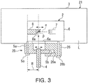
- FIGS. 3 , 4A , 4B , and 4C a second embodiment and a third embodiment of an X-ray generation source and fluorescent X-rays analyzer according to the present invention are described with reference to FIGS. 3 , 4A , 4B , and 4C .
- the same components described in the previous embodiment are given the same reference numerals and not described.
- a device holder 25 has a guide 26 for guiding the supporting extension 5b such that the supporting extension 5b can thermally extend in the extension direction, as shown in FIG. 3 . That is, in the second embodiment, the guide 26, which is disposed around the free end of the supporting extension 5b and has a groove 26a having a U-shaped cross-section to support the top and bottom of the supporting extension 5b, is fixed to the bottom of the housing 3 by a bolt 26b.
- the groove 26a is formed deep in the extension direction of the supporting extension 5b and the supporting extension 5b is inserted in the groove 26a. Accordingly, the supporting extension 5b can extend/contract in the extension direction with the top and bottom retained.
- the guide is made of a low-thermal expansion material such as steel, Fe-Ni 36% alloy or cast iron having a graphite structure in an austenitic iron matrix.
- the guide 26 that guides the supporting extension 5b of the device holder 5 capable of thermally expanding in the extension direction, the supporting extension 5b is guided by the guide 26 and the supporting extension 5b is prevented from bending up/down in thermal expansion, so it is possible to prevent vertical misalignment.
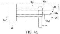
- the guide 26 supports the top and bottom of the supporting extension 5b in the second embodiment
- the X-ray generator 1 has a guide 36 having a pair of support rods 36 that can support both sides of the supporting extension 5b, as shown in FIGS. 4A to 4C .
- the guide 36 has a pair of support rods 36 having bases fixed to the fixed-base 5a and a slit 36a in which free end 35c of a supporting extension 35b is fitted to be movable in the extension direction of the support rods 36 is formed on the inner sides of the support rods 36.
- the supporting extension 35b has an extension rod 35b extending in the protrusion direction of the target unit 8 and a pair of free ends 35c protruding to both sides from the free end of the extension rod 35b. That is, the supporting extension 35b has a T-shape, when seen from above.
- the ends of the free ends 35c are fitted in the slits 36a, so the free end 35c can move in the extension direction of the extension rod 35b. Further, the X-ray radiation area controller 4 that is a poly-capillary is attached between the pair of free ends 35c.
- the supporting extension 35b is supported not only vertically, but laterally by the guide 26, so the supporting extension 35b is prevented from bending not only vertically, but laterally in thermal expansion. Accordingly, it is possible to prevent not only vertical misalignment, but lateral misalignment (horizontal, perpendicular to the extension direction).
- the present invention has been applied to an energy division type of fluorescent X-ray analyzer that measures the energy and intensity of X-rays using a pulse height analyzer in the embodiments, but it may be applied to a wavelength analysis type of fluorescent X-ray analyzing unit that divides fluorescent X-rays using a spectrum crystal and measures the wavelength and intensity of the X-ray.
Landscapes
- Physics & Mathematics (AREA)
- Health & Medical Sciences (AREA)
- Life Sciences & Earth Sciences (AREA)
- Chemical & Material Sciences (AREA)
- Analytical Chemistry (AREA)
- Biochemistry (AREA)
- General Health & Medical Sciences (AREA)
- General Physics & Mathematics (AREA)
- Immunology (AREA)
- Pathology (AREA)
- Analysing Materials By The Use Of Radiation (AREA)
- X-Ray Techniques (AREA)
Claims (4)
- Röntgengenerator, umfassend:eine Röntgenröhre (2), die zum Ausstrahlen von Primär-Röntgenstrahlen (X1) auf eine Probe (S) angepasst ist,ein Gehäuse (3), das die Röntgenröhre (2) enthält;einen Röntgenstrahlungsbereichsregler (4), der einen Strahlungsbereich der Primär-Röntgenstrahlen (X1) von einer Röntgenröhre (2) auf die Probe (S) begrenzt,einen Gerätehalter (5), der den Röntgenstrahlungsbereichsregler (4) in Bezug auf das Gehäuse (3) festhält,wobei die Röntgenröhre (2) umfasst: ein Vakuumgehäuse (6), eine als Kathode im Gehäuse (6) angeordnete Elektronenstrahlenquelle (7), die Elektronenstrahlen (e) erzeugt, und eine der Strahlenquelle (7) im Gehäuse (6) als Anode zugewandte Zieleinheit (8) mit einer auf dem Gehäuse (6) befestigten Basis, wobei die Zieleinheit durch ein hervorstehendes freies Ende (8a) Elektronenstrahlen (e) aufnimmt,dadurch gekennzeichnet, dass der Gerätehalter (5) umfasst: eine unmittelbar unter der Basis der Zieleinheit (8) auf dem Gehäuse (3) befestigte feste Basis (5a) und eine tragende Verlängerung (5b), die sich von der festen Basis (5a) in Richtung des Hervorstehens der Zieleinheit (8) erstreckt und den Regler (4) trägt,wobei eine Wärmeausdehnungsrate der Verlängerung (5b) in Richtung des Hervorstehens (X+) gleich einer Wärmeausdehnungsrate der Zieleinheit (8) in Richtung des Hervorstehens (X+) ist undein Abstand (R) von einem auf dem Gehäuse (3) befestigten Abschnitt der Verlängerung (5b) zu einer zentralen Achse des Reglers (4) gleich einem Abstand zwischen der Basis und einer Röntgenerzeugungsstellung (P) am freien Ende (8a) der Zieleinheit (8) ist.
- Röntgengenerator nach Anspruch 1, dadurch gekennzeichnet, dass die tragende Verlängerung (5b) aus dem gleichen Material besteht wie die Zieleinheit (8).
- Röntgengenerator nach Anspruch 1 oder 2, dadurch gekennzeichnet, dass der Gerätehalter (5) eine Führung (26) aufweist, die die tragende Verlängerung (5b) führt, so dass die tragende Verlängerung (5b) sich in Richtung des Hervorstehens thermisch ausdehnen kann.
- Röntgenfluoreszenz-Analysegerät, umfassend den Röntgengenerator nach einem der Ansprüche 1 - 3 und einen Detektor (14), der fluoreszierende Röntgenstrahlen (X2), die von der Probe (S) ausgehen, die die Primär-Röntgenstrahlen (X1) aufnimmt.
Applications Claiming Priority (1)
| Application Number | Priority Date | Filing Date | Title |
|---|---|---|---|
| JP2014217924A JP6320898B2 (ja) | 2014-10-27 | 2014-10-27 | X線発生源及び蛍光x線分析装置 |
Publications (2)
| Publication Number | Publication Date |
|---|---|
| EP3016482A1 EP3016482A1 (de) | 2016-05-04 |
| EP3016482B1 true EP3016482B1 (de) | 2020-04-15 |
Family
ID=54014651
Family Applications (1)
| Application Number | Title | Priority Date | Filing Date |
|---|---|---|---|
| EP15183160.9A Active EP3016482B1 (de) | 2014-10-27 | 2015-08-31 | Röntgengenerator und röntgenfluoreszenzanalysator |
Country Status (5)
| Country | Link |
|---|---|
| US (1) | US9721749B2 (de) |
| EP (1) | EP3016482B1 (de) |
| JP (1) | JP6320898B2 (de) |
| KR (1) | KR102301799B1 (de) |
| CN (1) | CN105548228B (de) |
Families Citing this family (2)
| Publication number | Priority date | Publication date | Assignee | Title |
|---|---|---|---|---|
| JP7123741B2 (ja) * | 2017-12-15 | 2022-08-23 | 株式会社堀場製作所 | X線検出装置及びx線検出方法 |
| KR102641674B1 (ko) * | 2023-08-31 | 2024-02-28 | 에프에스케이 주식회사 | 소형화 차폐구조를 포함하는 고전압 x선 탱크 |
Family Cites Families (24)
| Publication number | Priority date | Publication date | Assignee | Title |
|---|---|---|---|---|
| US3329816A (en) * | 1964-08-24 | 1967-07-04 | Field Emission Corp | High frequency coaxial transmission line for supporting a field emission cathode x-ray tube |
| US4166231A (en) * | 1977-10-07 | 1979-08-28 | The Machlett Laboratories, Inc. | Transverse beam x-ray tube |
| FR2415365A1 (fr) | 1978-01-24 | 1979-08-17 | Radiologie Cie Gle | Dispositif de reduction de la divergence du faisceau utile d'un tube a rayons x, et tube ainsi equipe |
| US4623523A (en) | 1979-01-02 | 1986-11-18 | Bechtel International Corporation | Method for reduction of SO2 emission for fossil fired boiler |
| DE3150172A1 (de) | 1981-12-18 | 1983-06-30 | Brown, Boveri & Cie Ag, 6800 Mannheim | Einrichtung zum einstellen und/oder ueberwachen der wirkungsweise eines geschosszuenders |
| JPS58111000U (ja) * | 1982-01-25 | 1983-07-28 | セイコーインスツルメンツ株式会社 | X線管放射軸調整装置 |
| JPS6251647U (de) * | 1985-09-20 | 1987-03-31 | ||
| JP3616121B2 (ja) * | 1993-10-29 | 2005-02-02 | 株式会社東芝 | X線管 |
| US6661876B2 (en) * | 2001-07-30 | 2003-12-09 | Moxtek, Inc. | Mobile miniature X-ray source |
| WO2003048745A2 (en) | 2001-12-04 | 2003-06-12 | X-Ray Optical Systems, Inc. | X-ray fluorescence analyser for analysing fluid streams using a semiconductor-type detector and focusing means |
| US7382856B2 (en) | 2001-12-04 | 2008-06-03 | X-Ray Optical Systems, Inc. | X-ray source assembly having enhanced output stability, and fluid stream analysis applications thereof |
| JP4322470B2 (ja) * | 2002-05-09 | 2009-09-02 | 浜松ホトニクス株式会社 | X線発生装置 |
| FR2846784B1 (fr) * | 2002-10-30 | 2005-02-11 | Ge Med Sys Global Tech Co Llc | Ensemble de palier pour le montage a rotation d'une anode rotative d'un dispositif d'emission de rayons x et dispositif d'emission de rayon x equipe d'un tel ensemble. |
| FI20031753L (fi) * | 2003-12-01 | 2005-06-02 | Metorex Internat Oy | Parannettu mittausjärjestely röntgenfluoresenssianalyysiä varten |
| US7286644B2 (en) * | 2004-04-28 | 2007-10-23 | Varian Medical Systems Technologies, Inc. | Systems, methods and devices for x-ray device focal spot control |
| US7568836B2 (en) | 2004-07-30 | 2009-08-04 | Neurologica Corp. | Mobile computerized tomography (CT) imaging system with off-center x-ray beam |
| JP5106789B2 (ja) * | 2006-05-31 | 2012-12-26 | 株式会社日立メディコ | X線管装置及びx線ct装置 |
| US20080037706A1 (en) * | 2006-08-08 | 2008-02-14 | Panalytical B.V. | Device and method for performing X-ray analysis |
| JP5780644B2 (ja) * | 2010-07-30 | 2015-09-16 | 株式会社リガク | 工業用x線発生装置 |
| JP5956730B2 (ja) * | 2011-08-05 | 2016-07-27 | 株式会社日立ハイテクサイエンス | X線分析装置及び方法 |
| JP6064456B2 (ja) * | 2012-09-04 | 2017-01-25 | 株式会社島津製作所 | X線管 |
| US9305739B2 (en) * | 2012-10-16 | 2016-04-05 | General Electric Company | Apparatus for ultra high vacuum thermal expansion compensation and method of constructing same |
| JP6082634B2 (ja) * | 2013-03-27 | 2017-02-15 | 株式会社日立ハイテクサイエンス | 蛍光x線分析装置 |
| JP6026936B2 (ja) * | 2013-03-28 | 2016-11-16 | 株式会社日立ハイテクサイエンス | 異物検出装置 |
-
2014
- 2014-10-27 JP JP2014217924A patent/JP6320898B2/ja active Active
-
2015
- 2015-07-21 KR KR1020150102950A patent/KR102301799B1/ko active Active
- 2015-08-27 US US14/837,745 patent/US9721749B2/en active Active
- 2015-08-31 EP EP15183160.9A patent/EP3016482B1/de active Active
- 2015-10-23 CN CN201510697826.2A patent/CN105548228B/zh active Active
Non-Patent Citations (1)
| Title |
|---|
| None * |
Also Published As
| Publication number | Publication date |
|---|---|
| CN105548228A (zh) | 2016-05-04 |
| US9721749B2 (en) | 2017-08-01 |
| EP3016482A1 (de) | 2016-05-04 |
| KR102301799B1 (ko) | 2021-09-14 |
| US20160118215A1 (en) | 2016-04-28 |
| JP2016085860A (ja) | 2016-05-19 |
| JP6320898B2 (ja) | 2018-05-09 |
| CN105548228B (zh) | 2018-07-24 |
| KR20160049440A (ko) | 2016-05-09 |
Similar Documents
| Publication | Publication Date | Title |
|---|---|---|
| US8903040B2 (en) | X-ray multiple spectroscopic analyzer | |
| CN104076052B (zh) | 荧光x射线分析装置 | |
| US8173952B2 (en) | Arrangement for producing electromagnetic radiation and method for operating said arrangement | |
| US6259763B1 (en) | X-ray imaging crystal spectrometer for extended X-ray sources | |
| JP2016038350A (ja) | X線透過検査装置及び異物検出方法 | |
| JP2004184314A (ja) | 蛍光x線分析装置 | |
| EP3016482B1 (de) | Röntgengenerator und röntgenfluoreszenzanalysator | |
| US9213007B2 (en) | Foreign matter detector | |
| US10908104B2 (en) | Radiation analysis apparatus | |
| Park et al. | X-ray beam-position feedback system with easy-to-use beam-position monitor | |
| CN113125483A (zh) | 一种轻小型地外行星原位定年仪及其定年方法 | |
| JP7701934B2 (ja) | 放射線検出モジュール、及び放射線検出装置 | |
| EP3538879B1 (de) | Gitterbasierte phasenkontrastbildgebung | |
| US6596994B1 (en) | Beam position monitor | |
| US6477237B1 (en) | X-ray shielding mechanism for off-axis X-rays | |
| Wincott et al. | Design and performance of a high-resolution electron energy analyser for angle-resolved photoemission spectroscopy | |
| KR102539723B1 (ko) | 전반사 형광 x선 분석 장치 | |
| US10497593B2 (en) | Bi-metal foil for a beam intensity/position monitor, method for determining mass absorption coefficients | |
| Grassi et al. | External scanning micro-PIXE for the characterization of a polycapillary lens: Measurement of the collected X-ray intensity distribution | |
| JP6475556B2 (ja) | 放射線検出器及び放射線検出装置 | |
| JP6328451B2 (ja) | 蛍光x線分析装置及びその制御方法 | |
| JP2019109220A (ja) | X線検出装置及びx線検出方法 | |
| Hampel et al. | Feasibility study for mega-electron-volt electron beam tomography | |
| Grasruck et al. | Characterization of focal spots of x-ray tubes in CT systems: method development and examples | |
| CZ30920U1 (cs) | Zařízení RTG absorpční spektrometrie optimalizované pro nízké toky fotonů |
Legal Events
| Date | Code | Title | Description |
|---|---|---|---|
| PUAI | Public reference made under article 153(3) epc to a published international application that has entered the european phase |
Free format text: ORIGINAL CODE: 0009012 |
|
| AK | Designated contracting states |
Kind code of ref document: A1 Designated state(s): AL AT BE BG CH CY CZ DE DK EE ES FI FR GB GR HR HU IE IS IT LI LT LU LV MC MK MT NL NO PL PT RO RS SE SI SK SM TR |
|
| AX | Request for extension of the european patent |
Extension state: BA ME |
|
| STAA | Information on the status of an ep patent application or granted ep patent |
Free format text: STATUS: REQUEST FOR EXAMINATION WAS MADE |
|
| 17P | Request for examination filed |
Effective date: 20161104 |
|
| RBV | Designated contracting states (corrected) |
Designated state(s): AL AT BE BG CH CY CZ DE DK EE ES FI FR GB GR HR HU IE IS IT LI LT LU LV MC MK MT NL NO PL PT RO RS SE SI SK SM TR |
|
| GRAP | Despatch of communication of intention to grant a patent |
Free format text: ORIGINAL CODE: EPIDOSNIGR1 |
|
| STAA | Information on the status of an ep patent application or granted ep patent |
Free format text: STATUS: GRANT OF PATENT IS INTENDED |
|
| INTG | Intention to grant announced |
Effective date: 20191204 |
|
| GRAS | Grant fee paid |
Free format text: ORIGINAL CODE: EPIDOSNIGR3 |
|
| GRAA | (expected) grant |
Free format text: ORIGINAL CODE: 0009210 |
|
| STAA | Information on the status of an ep patent application or granted ep patent |
Free format text: STATUS: THE PATENT HAS BEEN GRANTED |
|
| AK | Designated contracting states |
Kind code of ref document: B1 Designated state(s): AL AT BE BG CH CY CZ DE DK EE ES FI FR GB GR HR HU IE IS IT LI LT LU LV MC MK MT NL NO PL PT RO RS SE SI SK SM TR |
|
| REG | Reference to a national code |
Ref country code: CH Ref legal event code: EP |
|
| REG | Reference to a national code |
Ref country code: DE Ref legal event code: R096 Ref document number: 602015050623 Country of ref document: DE |
|
| REG | Reference to a national code |
Ref country code: IE Ref legal event code: FG4D |
|
| REG | Reference to a national code |
Ref country code: AT Ref legal event code: REF Ref document number: 1258807 Country of ref document: AT Kind code of ref document: T Effective date: 20200515 |
|
| REG | Reference to a national code |
Ref country code: NL Ref legal event code: MP Effective date: 20200415 |
|
| REG | Reference to a national code |
Ref country code: LT Ref legal event code: MG4D |
|
| PG25 | Lapsed in a contracting state [announced via postgrant information from national office to epo] |
Ref country code: LT Free format text: LAPSE BECAUSE OF FAILURE TO SUBMIT A TRANSLATION OF THE DESCRIPTION OR TO PAY THE FEE WITHIN THE PRESCRIBED TIME-LIMIT Effective date: 20200415 Ref country code: NL Free format text: LAPSE BECAUSE OF FAILURE TO SUBMIT A TRANSLATION OF THE DESCRIPTION OR TO PAY THE FEE WITHIN THE PRESCRIBED TIME-LIMIT Effective date: 20200415 Ref country code: SE Free format text: LAPSE BECAUSE OF FAILURE TO SUBMIT A TRANSLATION OF THE DESCRIPTION OR TO PAY THE FEE WITHIN THE PRESCRIBED TIME-LIMIT Effective date: 20200415 Ref country code: PT Free format text: LAPSE BECAUSE OF FAILURE TO SUBMIT A TRANSLATION OF THE DESCRIPTION OR TO PAY THE FEE WITHIN THE PRESCRIBED TIME-LIMIT Effective date: 20200817 Ref country code: FI Free format text: LAPSE BECAUSE OF FAILURE TO SUBMIT A TRANSLATION OF THE DESCRIPTION OR TO PAY THE FEE WITHIN THE PRESCRIBED TIME-LIMIT Effective date: 20200415 Ref country code: IS Free format text: LAPSE BECAUSE OF FAILURE TO SUBMIT A TRANSLATION OF THE DESCRIPTION OR TO PAY THE FEE WITHIN THE PRESCRIBED TIME-LIMIT Effective date: 20200815 Ref country code: NO Free format text: LAPSE BECAUSE OF FAILURE TO SUBMIT A TRANSLATION OF THE DESCRIPTION OR TO PAY THE FEE WITHIN THE PRESCRIBED TIME-LIMIT Effective date: 20200715 Ref country code: GR Free format text: LAPSE BECAUSE OF FAILURE TO SUBMIT A TRANSLATION OF THE DESCRIPTION OR TO PAY THE FEE WITHIN THE PRESCRIBED TIME-LIMIT Effective date: 20200716 |
|
| REG | Reference to a national code |
Ref country code: AT Ref legal event code: MK05 Ref document number: 1258807 Country of ref document: AT Kind code of ref document: T Effective date: 20200415 |
|
| PG25 | Lapsed in a contracting state [announced via postgrant information from national office to epo] |
Ref country code: RS Free format text: LAPSE BECAUSE OF FAILURE TO SUBMIT A TRANSLATION OF THE DESCRIPTION OR TO PAY THE FEE WITHIN THE PRESCRIBED TIME-LIMIT Effective date: 20200415 Ref country code: LV Free format text: LAPSE BECAUSE OF FAILURE TO SUBMIT A TRANSLATION OF THE DESCRIPTION OR TO PAY THE FEE WITHIN THE PRESCRIBED TIME-LIMIT Effective date: 20200415 Ref country code: BG Free format text: LAPSE BECAUSE OF FAILURE TO SUBMIT A TRANSLATION OF THE DESCRIPTION OR TO PAY THE FEE WITHIN THE PRESCRIBED TIME-LIMIT Effective date: 20200715 Ref country code: HR Free format text: LAPSE BECAUSE OF FAILURE TO SUBMIT A TRANSLATION OF THE DESCRIPTION OR TO PAY THE FEE WITHIN THE PRESCRIBED TIME-LIMIT Effective date: 20200415 |
|
| PG25 | Lapsed in a contracting state [announced via postgrant information from national office to epo] |
Ref country code: AL Free format text: LAPSE BECAUSE OF FAILURE TO SUBMIT A TRANSLATION OF THE DESCRIPTION OR TO PAY THE FEE WITHIN THE PRESCRIBED TIME-LIMIT Effective date: 20200415 |
|
| REG | Reference to a national code |
Ref country code: DE Ref legal event code: R097 Ref document number: 602015050623 Country of ref document: DE |
|
| PG25 | Lapsed in a contracting state [announced via postgrant information from national office to epo] |
Ref country code: ES Free format text: LAPSE BECAUSE OF FAILURE TO SUBMIT A TRANSLATION OF THE DESCRIPTION OR TO PAY THE FEE WITHIN THE PRESCRIBED TIME-LIMIT Effective date: 20200415 Ref country code: CZ Free format text: LAPSE BECAUSE OF FAILURE TO SUBMIT A TRANSLATION OF THE DESCRIPTION OR TO PAY THE FEE WITHIN THE PRESCRIBED TIME-LIMIT Effective date: 20200415 Ref country code: RO Free format text: LAPSE BECAUSE OF FAILURE TO SUBMIT A TRANSLATION OF THE DESCRIPTION OR TO PAY THE FEE WITHIN THE PRESCRIBED TIME-LIMIT Effective date: 20200415 Ref country code: AT Free format text: LAPSE BECAUSE OF FAILURE TO SUBMIT A TRANSLATION OF THE DESCRIPTION OR TO PAY THE FEE WITHIN THE PRESCRIBED TIME-LIMIT Effective date: 20200415 Ref country code: IT Free format text: LAPSE BECAUSE OF FAILURE TO SUBMIT A TRANSLATION OF THE DESCRIPTION OR TO PAY THE FEE WITHIN THE PRESCRIBED TIME-LIMIT Effective date: 20200415 Ref country code: SM Free format text: LAPSE BECAUSE OF FAILURE TO SUBMIT A TRANSLATION OF THE DESCRIPTION OR TO PAY THE FEE WITHIN THE PRESCRIBED TIME-LIMIT Effective date: 20200415 Ref country code: EE Free format text: LAPSE BECAUSE OF FAILURE TO SUBMIT A TRANSLATION OF THE DESCRIPTION OR TO PAY THE FEE WITHIN THE PRESCRIBED TIME-LIMIT Effective date: 20200415 Ref country code: DK Free format text: LAPSE BECAUSE OF FAILURE TO SUBMIT A TRANSLATION OF THE DESCRIPTION OR TO PAY THE FEE WITHIN THE PRESCRIBED TIME-LIMIT Effective date: 20200415 |
|
| PLBE | No opposition filed within time limit |
Free format text: ORIGINAL CODE: 0009261 |
|
| STAA | Information on the status of an ep patent application or granted ep patent |
Free format text: STATUS: NO OPPOSITION FILED WITHIN TIME LIMIT |
|
| PG25 | Lapsed in a contracting state [announced via postgrant information from national office to epo] |
Ref country code: SK Free format text: LAPSE BECAUSE OF FAILURE TO SUBMIT A TRANSLATION OF THE DESCRIPTION OR TO PAY THE FEE WITHIN THE PRESCRIBED TIME-LIMIT Effective date: 20200415 Ref country code: PL Free format text: LAPSE BECAUSE OF FAILURE TO SUBMIT A TRANSLATION OF THE DESCRIPTION OR TO PAY THE FEE WITHIN THE PRESCRIBED TIME-LIMIT Effective date: 20200415 |
|
| 26N | No opposition filed |
Effective date: 20210118 |
|
| PG25 | Lapsed in a contracting state [announced via postgrant information from national office to epo] |
Ref country code: MC Free format text: LAPSE BECAUSE OF FAILURE TO SUBMIT A TRANSLATION OF THE DESCRIPTION OR TO PAY THE FEE WITHIN THE PRESCRIBED TIME-LIMIT Effective date: 20200415 |
|
| REG | Reference to a national code |
Ref country code: CH Ref legal event code: PL |
|
| GBPC | Gb: european patent ceased through non-payment of renewal fee |
Effective date: 20200831 |
|
| PG25 | Lapsed in a contracting state [announced via postgrant information from national office to epo] |
Ref country code: LI Free format text: LAPSE BECAUSE OF NON-PAYMENT OF DUE FEES Effective date: 20200831 Ref country code: LU Free format text: LAPSE BECAUSE OF NON-PAYMENT OF DUE FEES Effective date: 20200831 Ref country code: CH Free format text: LAPSE BECAUSE OF NON-PAYMENT OF DUE FEES Effective date: 20200831 |
|
| REG | Reference to a national code |
Ref country code: BE Ref legal event code: MM Effective date: 20200831 |
|
| PG25 | Lapsed in a contracting state [announced via postgrant information from national office to epo] |
Ref country code: SI Free format text: LAPSE BECAUSE OF FAILURE TO SUBMIT A TRANSLATION OF THE DESCRIPTION OR TO PAY THE FEE WITHIN THE PRESCRIBED TIME-LIMIT Effective date: 20200415 |
|
| PG25 | Lapsed in a contracting state [announced via postgrant information from national office to epo] |
Ref country code: FR Free format text: LAPSE BECAUSE OF NON-PAYMENT OF DUE FEES Effective date: 20200831 |
|
| PG25 | Lapsed in a contracting state [announced via postgrant information from national office to epo] |
Ref country code: IE Free format text: LAPSE BECAUSE OF NON-PAYMENT OF DUE FEES Effective date: 20200831 Ref country code: GB Free format text: LAPSE BECAUSE OF NON-PAYMENT OF DUE FEES Effective date: 20200831 Ref country code: BE Free format text: LAPSE BECAUSE OF NON-PAYMENT OF DUE FEES Effective date: 20200831 |
|
| PG25 | Lapsed in a contracting state [announced via postgrant information from national office to epo] |
Ref country code: TR Free format text: LAPSE BECAUSE OF FAILURE TO SUBMIT A TRANSLATION OF THE DESCRIPTION OR TO PAY THE FEE WITHIN THE PRESCRIBED TIME-LIMIT Effective date: 20200415 Ref country code: MT Free format text: LAPSE BECAUSE OF FAILURE TO SUBMIT A TRANSLATION OF THE DESCRIPTION OR TO PAY THE FEE WITHIN THE PRESCRIBED TIME-LIMIT Effective date: 20200415 Ref country code: CY Free format text: LAPSE BECAUSE OF FAILURE TO SUBMIT A TRANSLATION OF THE DESCRIPTION OR TO PAY THE FEE WITHIN THE PRESCRIBED TIME-LIMIT Effective date: 20200415 |
|
| PG25 | Lapsed in a contracting state [announced via postgrant information from national office to epo] |
Ref country code: MK Free format text: LAPSE BECAUSE OF FAILURE TO SUBMIT A TRANSLATION OF THE DESCRIPTION OR TO PAY THE FEE WITHIN THE PRESCRIBED TIME-LIMIT Effective date: 20200415 |
|
| REG | Reference to a national code |
Ref country code: DE Ref legal event code: R081 Ref document number: 602015050623 Country of ref document: DE Owner name: HITACHI HIGH-TECH ANALYSIS CORPORATION, JP Free format text: FORMER OWNER: HITACHI HIGH-TECH SCIENCE CORPORATION, TOKYO, JP |
|
| PGFP | Annual fee paid to national office [announced via postgrant information from national office to epo] |
Ref country code: DE Payment date: 20250702 Year of fee payment: 11 |