EP3012017A1 - Auskleidungsstruktur - Google Patents
Auskleidungsstruktur Download PDFInfo
- Publication number
- EP3012017A1 EP3012017A1 EP14813063.6A EP14813063A EP3012017A1 EP 3012017 A1 EP3012017 A1 EP 3012017A1 EP 14813063 A EP14813063 A EP 14813063A EP 3012017 A1 EP3012017 A1 EP 3012017A1
- Authority
- EP
- European Patent Office
- Prior art keywords
- section
- lining
- flange
- base material
- tube
- Prior art date
- Legal status (The legal status is an assumption and is not a legal conclusion. Google has not performed a legal analysis and makes no representation as to the accuracy of the status listed.)
- Granted
Links
- 239000000463 material Substances 0.000 claims abstract description 55
- 239000000126 substance Substances 0.000 claims abstract description 33
- 238000003780 insertion Methods 0.000 claims abstract description 24
- 230000037431 insertion Effects 0.000 claims abstract description 24
- 238000002386 leaching Methods 0.000 claims abstract description 10
- PXHVJJICTQNCMI-UHFFFAOYSA-N Nickel Chemical compound [Ni] PXHVJJICTQNCMI-UHFFFAOYSA-N 0.000 claims description 12
- 229910052759 nickel Inorganic materials 0.000 claims description 6
- 230000002378 acidificating effect Effects 0.000 claims description 5
- 239000002002 slurry Substances 0.000 claims description 5
- 229910000480 nickel oxide Inorganic materials 0.000 claims description 4
- GNRSAWUEBMWBQH-UHFFFAOYSA-N oxonickel Chemical compound [Ni]=O GNRSAWUEBMWBQH-UHFFFAOYSA-N 0.000 claims description 4
- 230000000116 mitigating effect Effects 0.000 abstract description 2
- 229910052751 metal Inorganic materials 0.000 description 7
- 239000002184 metal Substances 0.000 description 7
- 239000010936 titanium Substances 0.000 description 6
- 238000003466 welding Methods 0.000 description 6
- 238000004519 manufacturing process Methods 0.000 description 5
- QAOWNCQODCNURD-UHFFFAOYSA-N Sulfuric acid Chemical compound OS(O)(=O)=O QAOWNCQODCNURD-UHFFFAOYSA-N 0.000 description 4
- 238000000034 method Methods 0.000 description 4
- RTAQQCXQSZGOHL-UHFFFAOYSA-N Titanium Chemical compound [Ti] RTAQQCXQSZGOHL-UHFFFAOYSA-N 0.000 description 3
- 239000002360 explosive Substances 0.000 description 3
- 229910052715 tantalum Inorganic materials 0.000 description 3
- GUVRBAGPIYLISA-UHFFFAOYSA-N tantalum atom Chemical compound [Ta] GUVRBAGPIYLISA-UHFFFAOYSA-N 0.000 description 3
- 229910052719 titanium Inorganic materials 0.000 description 3
- 238000005452 bending Methods 0.000 description 2
- 230000000694 effects Effects 0.000 description 2
- 238000009854 hydrometallurgy Methods 0.000 description 2
- 238000007689 inspection Methods 0.000 description 2
- 238000009434 installation Methods 0.000 description 2
- 238000003754 machining Methods 0.000 description 2
- 230000000737 periodic effect Effects 0.000 description 2
- 229910017052 cobalt Inorganic materials 0.000 description 1
- 239000010941 cobalt Substances 0.000 description 1
- GUTLYIVDDKVIGB-UHFFFAOYSA-N cobalt atom Chemical compound [Co] GUTLYIVDDKVIGB-UHFFFAOYSA-N 0.000 description 1
- 238000011109 contamination Methods 0.000 description 1
- 238000005260 corrosion Methods 0.000 description 1
- 230000007797 corrosion Effects 0.000 description 1
- 239000012530 fluid Substances 0.000 description 1
Images


Classifications
-
- B—PERFORMING OPERATIONS; TRANSPORTING
- B01—PHYSICAL OR CHEMICAL PROCESSES OR APPARATUS IN GENERAL
- B01J—CHEMICAL OR PHYSICAL PROCESSES, e.g. CATALYSIS OR COLLOID CHEMISTRY; THEIR RELEVANT APPARATUS
- B01J3/00—Processes of utilising sub-atmospheric or super-atmospheric pressure to effect chemical or physical change of matter; Apparatus therefor
- B01J3/02—Feed or outlet devices therefor
-
- B—PERFORMING OPERATIONS; TRANSPORTING
- B01—PHYSICAL OR CHEMICAL PROCESSES OR APPARATUS IN GENERAL
- B01J—CHEMICAL OR PHYSICAL PROCESSES, e.g. CATALYSIS OR COLLOID CHEMISTRY; THEIR RELEVANT APPARATUS
- B01J19/00—Chemical, physical or physico-chemical processes in general; Their relevant apparatus
- B01J19/02—Apparatus characterised by being constructed of material selected for its chemically-resistant properties
-
- B—PERFORMING OPERATIONS; TRANSPORTING
- B01—PHYSICAL OR CHEMICAL PROCESSES OR APPARATUS IN GENERAL
- B01J—CHEMICAL OR PHYSICAL PROCESSES, e.g. CATALYSIS OR COLLOID CHEMISTRY; THEIR RELEVANT APPARATUS
- B01J4/00—Feed or outlet devices; Feed or outlet control devices
- B01J4/001—Feed or outlet devices as such, e.g. feeding tubes
-
- B—PERFORMING OPERATIONS; TRANSPORTING
- B01—PHYSICAL OR CHEMICAL PROCESSES OR APPARATUS IN GENERAL
- B01J—CHEMICAL OR PHYSICAL PROCESSES, e.g. CATALYSIS OR COLLOID CHEMISTRY; THEIR RELEVANT APPARATUS
- B01J2219/00—Chemical, physical or physico-chemical processes in general; Their relevant apparatus
- B01J2219/02—Apparatus characterised by their chemically-resistant properties
- B01J2219/0204—Apparatus characterised by their chemically-resistant properties comprising coatings on the surfaces in direct contact with the reactive components
- B01J2219/0236—Metal based
-
- B—PERFORMING OPERATIONS; TRANSPORTING
- B29—WORKING OF PLASTICS; WORKING OF SUBSTANCES IN A PLASTIC STATE IN GENERAL
- B29C—SHAPING OR JOINING OF PLASTICS; SHAPING OF MATERIAL IN A PLASTIC STATE, NOT OTHERWISE PROVIDED FOR; AFTER-TREATMENT OF THE SHAPED PRODUCTS, e.g. REPAIRING
- B29C63/00—Lining or sheathing, i.e. applying preformed layers or sheathings of plastics; Apparatus therefor
- B29C63/26—Lining or sheathing of internal surfaces
- B29C63/34—Lining or sheathing of internal surfaces using tubular layers or sheathings
-
- F—MECHANICAL ENGINEERING; LIGHTING; HEATING; WEAPONS; BLASTING
- F16—ENGINEERING ELEMENTS AND UNITS; GENERAL MEASURES FOR PRODUCING AND MAINTAINING EFFECTIVE FUNCTIONING OF MACHINES OR INSTALLATIONS; THERMAL INSULATION IN GENERAL
- F16L—PIPES; JOINTS OR FITTINGS FOR PIPES; SUPPORTS FOR PIPES, CABLES OR PROTECTIVE TUBING; MEANS FOR THERMAL INSULATION IN GENERAL
- F16L58/00—Protection of pipes or pipe fittings against corrosion or incrustation
- F16L58/02—Protection of pipes or pipe fittings against corrosion or incrustation by means of internal or external coatings
- F16L58/04—Coatings characterised by the materials used
- F16L58/08—Coatings characterised by the materials used by metal
-
- Y—GENERAL TAGGING OF NEW TECHNOLOGICAL DEVELOPMENTS; GENERAL TAGGING OF CROSS-SECTIONAL TECHNOLOGIES SPANNING OVER SEVERAL SECTIONS OF THE IPC; TECHNICAL SUBJECTS COVERED BY FORMER USPC CROSS-REFERENCE ART COLLECTIONS [XRACs] AND DIGESTS
- Y02—TECHNOLOGIES OR APPLICATIONS FOR MITIGATION OR ADAPTATION AGAINST CLIMATE CHANGE
- Y02P—CLIMATE CHANGE MITIGATION TECHNOLOGIES IN THE PRODUCTION OR PROCESSING OF GOODS
- Y02P10/00—Technologies related to metal processing
- Y02P10/20—Recycling
Definitions
- the present invention relates to a lining structure which is effective for a measure against damage of a lining member due to a difference in thermal expansion under high temperature and high pressure.
- the lining member is provided on a metal base material of an insertion tube for adding a chemical used for adding a chemical to a reaction vessel for leaching under high temperature and high pressure.
- Patent Literature 1 there is a technique in which a lining member is provided within a tube to prevent leakage of fluid of high temperature or high pressure, or to protect the tube from corrosion, wear, contamination, or the like.
- a lining member 120 is provided on a base material member 110 of an insertion tube 103 for adding a chemical used for adding an acidic chemical to an autoclave 102, and a metal lining is applied by the lining member 120.
- the base material member 110 has, for example, a cylindrical tube section 111 and a flange section 112 that protrudes outward at one end of the tube section 111, and is formed of a metal base material, such as Ti (titanium).
- the lining member 120 has, for example, a cylindrical tube section lining section 121 provided on an inner surface 111 a of the tube section 111 of the base material member 110 and a disc-shaped flange lining section 122 provided on the flange section 112 of the base material member 110, and is formed of a lining material, such as Ta (tantalum).
- the lining material of the flange lining section 122 is explosively welded to the flange section 112 of the flat base material member 110, and the flange lining section 122 is joined to the tube section lining section 121 by welding.
- a conventional insertion tube 103 for adding a chemical has a structure that the tube section lining section 121 and the flange lining section 122 are joined substantially orthogonally.
- the autoclave 102 is in a predetermined high temperature and high pressure state during operation. However, during periodic inspection, repair, or the like, the temperature and even the atmospheric pressure of the autoclave 102 are lowered, and the autoclave 102 is in a normal temperature and normal pressure state. Accordingly, a difference in thermal expansion occurs between the base material member 110 and the lining member 120 that normally have a difference in coefficients of thermal expansion. Moreover, it is structured that the flange lining section 122 is explosively welded to the flange section 112 of the base material member 110 and is joined to the tube section lining section 121 by welding, and that the tube section lining section 121 and the flange lining section 122 are joined substantially orthogonally. Consequently, it is structured that stress due to the difference in thermal expansion is concentrated on the flange lining section 122.
- the metal base material is Ti (titanium)
- a coefficient of thermal expansion thereof is approximately 8 to 9 ⁇ m m -1 ⁇ K -1
- the lining material is Ta (tantalum)
- a coefficient of thermal expansion thereof is approximately 6 to 7 ⁇ m ⁇ m -1 ⁇ K -1
- the coefficient of thermal expansion of the lining member 120 is smaller than that of the base material member 110 by about 30 percent.
- the lining member 120 having a smaller coefficient of thermal expansion cannot absorb the expansion of the flange section 112, and a crack occurs in the lining member 120. Accordingly, there is a possibility that the base material member 110 of the insertion tube 103 for adding a chemical and a nozzle section of the autoclave 102 are damaged.
- Patent document 1 Japanese Laid-Open Patent Publication 2008-128255
- the present invention is made to solve such a situation, and an object thereof is to provide a lining structure capable of mitigating stress concentration due to a difference in thermal expansion and preventing damage of a lining member.
- a lining structure according to the present invention is a lining structure of a lining member provided on a base material of an insertion tube used for adding a chemical to a reaction vessel for leaching under high temperature and high pressure, wherein the base material has a tube section and a flange section, the lining member is provided on the base material and formed of a material different from the base material, and the lining member has a tube section lining section provided on the tube section and a flange lining section provided on the flange section, a chamfer section is formed on the flange section, the tube section lining section is protruded to the same height as a flat surface of the flange lining section, and the flange lining section has a curved surface section protruded toward the base material side on the chamfer section and is welded to a protruding section of the tube section lining section that protrudes from a slant surface of the chamfer section.
- a width range of the chamfer section may be within a range from 1/4W to 1/2W, and when a thickness of the flange section is D, a depth range of the chamfer section may be within a range from 1/3D to 1/2D.
- the reaction vessel can be used suitably as a vessel at least leaching nickel from nickel oxide ore slurry.
- a chamfer width of a corner section of a flange section is increased by providing a chamfer section at the flange section of a base material, a tube section lining section of the lining member is protruded to the same height as a flat upper surface of a flange lining section, and further, bending work is applied to the flange lining section of the lining member. Accordingly, even when an insertion tube is thermally expanded under high temperature and high pressure, the lining member can follow the expansion and can absorb a difference in thermal expansion even in a reaction under the high temperature and high pressure, and damage of the lining member can be prevented.
- the present invention it is possible to suppress a risk of jetting out high pressure steam or a chemical and a risk, such as a loss caused by stopping a production facility due to replacement work or repair work of the insertion tube for adding a chemical accompanied by the damage of the lining member. Further, according to the present invention, since explosive welding is not needed, a manufacturing process can be simplified.
- a lining structure 1 prevents occurrence of a crack in a lining member 20, the lining member 20 serving as a lining and being provided on a base material member 10 of an insertion tube 3 for adding a chemical used for adding an acidic chemical to a reaction vessel 2, e.g., an autoclave, for leaching nickel or cobalt from nickel oxide ore slurry under high temperature and high pressure in a nickel hydrometallurgical process or the like using a high pressure sulfuric acid leaching process.
- a reaction vessel 2 e.g., an autoclave
- the insertion tube 3 for adding a chemical has a base material member 10 and a lining member 20 provided on the base material member 10 and serves as the lining.
- the base material member 10 has a cylindrical tube section 11 and a flange section 12 that protrudes outward at one end of the tube section 11, and is formed of a metal base material, such as Ti (titanium).
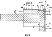
- the flange section 12 is formed into a planar shape and formed with a chamfer section 13 provided in a slanted manner so as to become gradually thin toward an inner side (a tube section 11 side) at a corner on the inner side (the tube section 11 side).
- the flange section 12 has a smooth flat section 12a and a chamfer section 13.
- the lining member 20 has a cylindrical tube section lining section 21 provided on an inner surface 11 a of the tube section 11 of the base material member 10 and a disc-shaped flange lining section 22 provided on the flange section 12 of the base material member 10, and is formed of a lining material, such as Ta (tantalum). Further, the tube section lining section 21 and the flange lining section 22 are integrated via the lining structure 1.
- the tube section lining section 21 is provided that one end section 21a has substantially the same height as a flat upper surface 22a of the flange lining section 22.
- the flange lining section 22 is provided along an upper surface of the flange section 12.
- the flange lining section 22 has a flat section 23 provided along the flat section 12a of the flange section 12 and a U-shaped or V-shaped curved surface section 24 bent toward a flange section 12 side (a lower side) and protruded on an inner side (a tube section lining section 21 side) of the flat section 23.
- the curved surface section 24 has a first curved surface section 24a provided along the chamfer section 13 and a second curved surface section 24b disposed over between the chamfer section 13 and a protruding section 21b.
- the protruding section 21b protrudes from a slant surface 13a of the chamfer section 13 on one end side of the tube section lining section 21.
- An end on the inner side (the tube section lining section 21 side) of the second curved surface section 24b is welded to the one end section 21a or the protruding section 21b of the tube section lining section 21, and the second curved surface section 24b is integrally provided with the tube section lining section 21.
- the tube section lining section 21 and the flange lining section 22 are integrally provided by the above-described lining structure 1. Further, the tube section lining section 21 and the flange lining section 22 are integrally provided by the lining structure 1, and the lining member 20, to which bending work has been applied, is installed in the base material member 10 by welding or the like and not by conventional explosive welding.
- the conventional lining structure has a structure in which the flange lining section 122 of the lining member 120 is explosively welded to the flange section 112 of the base material member 110 and is joined to the tube section lining section 121, and the tube section lining section 121 and the flange lining section 122 are joined substantially orthogonally.
- the chamfer section 13 is formed on the flange section 12, and the tube section lining section 21 is protruded to the same height as the flat upper surface 22a of the flange lining section 22.
- the flange lining section 22 has the curved surface section 24 protruded toward a base material member 10 side on the chamfer section 13 and welded with the protruding section 21b of the tube section lining section 21. Accordingly, even when the insertion tube 3 for adding a chemical is thermally expanded under high temperature and high pressure, the lining member 20 having a small coefficient of thermal expansion can follow the expansion and can absorb a difference in thermal expansion even in a reaction under high temperature and high pressure.
- the lining structure 1 even when the lining member 20 formed of the lining material having a coefficient of expansion smaller than that of the metal base material of the base material member 10 is used in an environment where high temperature and high pressure and normal temperature and normal pressure are repeated, occurrence of stress concentration in which a crack occurs in the lining member 20 can be prevented.
- the lining structure 1 can prevent occurrence of a crack in the lining member 20 than before. Accordingly, the lining structure 1 can suppress a risk of jetting out high pressure steam or a chemical and a risk, such as a loss caused by stopping a production facility due to replacement work or repair work of the insertion tube for adding a chemical accompanied by the occurrence of the crack in the lining member 20.
- a width range w of the chamfer section 13 of the base material member 10 may be set within a range from 1/4W to 1/2W.
- the width range is smaller than or equal to 1/2W, strength of the base material member 10 can be sufficiently secured during machining or during installation, and when the width range is greater than or equal to 1/4W, the curved surface section 24 can be made large to a degree that alleviation of stress can be sufficiently secured.
- a depth ranged of the chamfer section 13 of the base material member 10 may be set within a range from 1/3D to 1/2D.
- the depth range is smaller than or equal to 1/2D, strength of the base material member 10 can be sufficiently secured during machining or during installation, and that, when the depth range is greater than or equal to 1/3D, the curved surface section 24 can be made large to a degree that alleviation of stress can be sufficiently secured.
- reaction vessel 2 should not be limited to the one for leaching nickel from nickel oxide ore slurry, and can be the one for leaching the other metal from another slurry.
- insertion tube 3 for adding a chemical should not be limited to the one for adding an acidic chemical to the reaction vessel, and can be the one for adding another chemical to the reaction vessel.
Landscapes
- Chemical & Material Sciences (AREA)
- Organic Chemistry (AREA)
- Chemical Kinetics & Catalysis (AREA)
- Manufacture And Refinement Of Metals (AREA)
- Rigid Pipes And Flexible Pipes (AREA)
- Physical Or Chemical Processes And Apparatus (AREA)
- Pressure Vessels And Lids Thereof (AREA)
- Protection Of Pipes Against Damage, Friction, And Corrosion (AREA)
Applications Claiming Priority (2)
| Application Number | Priority Date | Filing Date | Title |
|---|---|---|---|
| JP2013127541A JP5729421B2 (ja) | 2013-06-18 | 2013-06-18 | ライニング構造 |
| PCT/JP2014/053130 WO2014203557A1 (ja) | 2013-06-18 | 2014-02-12 | ライニング構造 |
Publications (3)
| Publication Number | Publication Date |
|---|---|
| EP3012017A1 true EP3012017A1 (de) | 2016-04-27 |
| EP3012017A4 EP3012017A4 (de) | 2017-03-29 |
| EP3012017B1 EP3012017B1 (de) | 2018-01-03 |
Family
ID=52104306
Family Applications (1)
| Application Number | Title | Priority Date | Filing Date |
|---|---|---|---|
| EP14813063.6A Not-in-force EP3012017B1 (de) | 2013-06-18 | 2014-02-12 | Auskleidungsstruktur |
Country Status (8)
| Country | Link |
|---|---|
| US (1) | US9381482B2 (de) |
| EP (1) | EP3012017B1 (de) |
| JP (1) | JP5729421B2 (de) |
| CN (1) | CN105307764B (de) |
| AU (1) | AU2014282613B2 (de) |
| CA (1) | CA2912812C (de) |
| PH (1) | PH12015502476B1 (de) |
| WO (1) | WO2014203557A1 (de) |
Families Citing this family (5)
| Publication number | Priority date | Publication date | Assignee | Title |
|---|---|---|---|---|
| CN109028959B (zh) * | 2016-11-16 | 2019-08-20 | 乐清市川嘉电气科技有限公司 | 一种防脱离硬质合金维护工具 |
| KR102759000B1 (ko) | 2018-09-18 | 2025-01-22 | 에이에스엠엘 네델란즈 비.브이. | 고압 연결 장치 |
| JP7380264B2 (ja) * | 2020-01-29 | 2023-11-15 | 住友金属鉱山株式会社 | オートクレーブの冷却器具及び冷却方法 |
| CN111594700B (zh) * | 2020-06-08 | 2025-02-25 | 临沂丰瓷新材料科技有限公司 | 管道及管道系统 |
| WO2026083396A1 (en) * | 2024-10-14 | 2026-04-23 | Pt Esg New Energy Material | Acid addition device and high-pressure vessel |
Family Cites Families (19)
| Publication number | Priority date | Publication date | Assignee | Title |
|---|---|---|---|---|
| US2216033A (en) * | 1938-06-01 | 1940-09-24 | Kellogg M W Co | Method of forming lined connectors |
| US3651558A (en) * | 1970-06-08 | 1972-03-28 | Dow Chemical Co | Method of repairing a ceramic-lined nozzle |
| JPS5853955U (ja) * | 1981-10-09 | 1983-04-12 | 株式会社神戸製鋼所 | 圧力容器におけるフランジ用鍔板取付構造 |
| JPS62267405A (ja) * | 1986-05-13 | 1987-11-20 | Nippon Steel Corp | 高温・高圧配管の熱膨張吸収方法 |
| US6543811B1 (en) * | 1996-12-02 | 2003-04-08 | Robert W. Campbell | Pipe flange assembly |
| JP2001050475A (ja) * | 1999-08-05 | 2001-02-23 | Osaka Gas Co Ltd | ライニング管とそのライニング管の製造方法 |
| JP2003254478A (ja) * | 2002-02-28 | 2003-09-10 | Kubota Corp | 管切断端面の防食部材 |
| KR100840953B1 (ko) | 2002-04-29 | 2008-06-24 | 까르본 로렌 에끼브망 제니 키미끄 | 금속 지지 부품과 부식방지 금속 코팅을 포함하는 화학 장치 구성요소를 제조하는 방법 |
| DE60210510T2 (de) * | 2002-08-09 | 2006-08-24 | Hatch Ltd., Mississauga | Isolierender einsatz für verfahrensbehälter mit erhöhten temperaturen |
| CN2572189Y (zh) * | 2002-09-28 | 2003-09-10 | 宜兴市宙斯泵业有限公司 | 一种改进的耐磨衬里管道弯头 |
| CN1415888A (zh) * | 2002-10-04 | 2003-05-07 | 宜兴市宙斯泵业有限公司 | 一种耐磨衬里管道弯头及衬里方法 |
| CN2646515Y (zh) * | 2003-10-30 | 2004-10-06 | 陈海渊 | 耐高温耐磨复合管 |
| US7922065B2 (en) * | 2004-08-02 | 2011-04-12 | Ati Properties, Inc. | Corrosion resistant fluid conducting parts, methods of making corrosion resistant fluid conducting parts and equipment and parts replacement methods utilizing corrosion resistant fluid conducting parts |
| JP4840690B2 (ja) * | 2006-02-22 | 2011-12-21 | 日立金属株式会社 | 管端防食部材および配管構造 |
| JP4779153B2 (ja) | 2006-11-16 | 2011-09-28 | 独立行政法人産業技術総合研究所 | 配管用継手 |
| JP5548477B2 (ja) * | 2010-02-23 | 2014-07-16 | 株式会社水道技術開発機構 | 金属管の端部防蝕構造及びそれに用いられる被覆カバー |
| JP5485774B2 (ja) * | 2010-04-07 | 2014-05-07 | カルボヌ ロレーヌ エキプマン ジェニ シミック | 金属製の支持部品および防食金属被覆を具備する化学装置の構成要素の製造方法 |
| DE102010024495A1 (de) * | 2010-06-21 | 2011-12-22 | Schott Ag | Auskleidungs- oder Reflektormaterial für Hochtemperaturanwendungen |
| CN102734589B (zh) * | 2012-06-02 | 2014-05-28 | 温州市氟塑设备制造厂 | 一种耐高正、负压聚四氟乙烯-金属复合补偿器制造方法及其产品 |
-
2013
- 2013-06-18 JP JP2013127541A patent/JP5729421B2/ja active Active
-
2014
- 2014-02-12 WO PCT/JP2014/053130 patent/WO2014203557A1/ja not_active Ceased
- 2014-02-12 AU AU2014282613A patent/AU2014282613B2/en active Active
- 2014-02-12 EP EP14813063.6A patent/EP3012017B1/de not_active Not-in-force
- 2014-02-12 US US14/891,872 patent/US9381482B2/en not_active Expired - Fee Related
- 2014-02-12 CN CN201480035113.3A patent/CN105307764B/zh not_active Expired - Fee Related
- 2014-02-12 CA CA2912812A patent/CA2912812C/en not_active Expired - Fee Related
-
2015
- 2015-10-27 PH PH12015502476A patent/PH12015502476B1/en unknown
Also Published As
| Publication number | Publication date |
|---|---|
| CA2912812A1 (en) | 2014-12-24 |
| EP3012017A4 (de) | 2017-03-29 |
| PH12015502476A1 (en) | 2016-02-22 |
| US9381482B2 (en) | 2016-07-05 |
| EP3012017B1 (de) | 2018-01-03 |
| CN105307764B (zh) | 2017-03-08 |
| JP2015000391A (ja) | 2015-01-05 |
| CA2912812C (en) | 2016-07-05 |
| AU2014282613A1 (en) | 2015-11-12 |
| US20160129412A1 (en) | 2016-05-12 |
| WO2014203557A1 (ja) | 2014-12-24 |
| PH12015502476B1 (en) | 2016-02-22 |
| JP5729421B2 (ja) | 2015-06-03 |
| AU2014282613B2 (en) | 2016-01-07 |
| CN105307764A (zh) | 2016-02-03 |
Similar Documents
| Publication | Publication Date | Title |
|---|---|---|
| EP3012017B1 (de) | Auskleidungsstruktur | |
| CN103502558B (zh) | 用于连接用于井底组件的管状元件的联接件 | |
| KR20170113648A (ko) | 버링 가공 방법 | |
| JP6873150B2 (ja) | 高外圧下で用いられるフィードスルーおよびその製造方法 | |
| KR102694081B1 (ko) | 고압 라인용 센서 및 그 제조 방법 | |
| JP5102908B1 (ja) | 金属ガスケット | |
| CN108120545B (zh) | 膜片、使用膜片的压力传感器、膜片的制造方法 | |
| KR102099384B1 (ko) | 씰부재 및 씰부재의 제조방법 | |
| EP3483489B1 (de) | Geprägter sitz für metall-metall-sitz | |
| JP5800102B2 (ja) | ライニング構造 | |
| JP2018035832A (ja) | 逆止弁 | |
| KR20110050116A (ko) | 파이프 연결구의 플랜지 가공방법 | |
| JP6977913B1 (ja) | プレス部品の製造方法、及びブランク材の製造方法 | |
| US20150062837A1 (en) | Lead frame for a premold sensor housing | |
| JP6037621B2 (ja) | 栓部材の取付構造 | |
| EP3483422B1 (de) | Endkappe | |
| EP3110575B1 (de) | Verfahren und kit zum verbinden eines rohrförmigen elements und einer rohrleitung zum fördern korrosiver produkte | |
| KR20180127925A (ko) | 진공장치용 전열판 및 그의 제조방법 | |
| US10520118B2 (en) | Tube fitting assembly | |
| JP5260773B1 (ja) | 金属ガスケット | |
| KR101653653B1 (ko) | 원자력 증기발생기의 튜브 지지막대 제조방법 | |
| KR101556102B1 (ko) | 열교환기 전열관의 기계식 관막음 장치 | |
| JP4051390B2 (ja) | アニーリング用治具 | |
| KR20130006329A (ko) | 냉간 압접 공법 및 냉간 압접 장치 |
Legal Events
| Date | Code | Title | Description |
|---|---|---|---|
| PUAI | Public reference made under article 153(3) epc to a published international application that has entered the european phase |
Free format text: ORIGINAL CODE: 0009012 |
|
| 17P | Request for examination filed |
Effective date: 20151029 |
|
| AK | Designated contracting states |
Kind code of ref document: A1 Designated state(s): AL AT BE BG CH CY CZ DE DK EE ES FI FR GB GR HR HU IE IS IT LI LT LU LV MC MK MT NL NO PL PT RO RS SE SI SK SM TR |
|
| AX | Request for extension of the european patent |
Extension state: BA ME |
|
| DAX | Request for extension of the european patent (deleted) | ||
| A4 | Supplementary search report drawn up and despatched |
Effective date: 20170301 |
|
| RIC1 | Information provided on ipc code assigned before grant |
Ipc: F16L 57/00 20060101ALI20170223BHEP Ipc: F16L 51/00 20060101ALI20170223BHEP Ipc: F16J 15/12 20060101ALI20170223BHEP Ipc: C22B 23/00 20060101ALI20170223BHEP Ipc: C22B 3/04 20060101ALI20170223BHEP Ipc: B01J 4/00 20060101ALN20170223BHEP Ipc: F16L 58/08 20060101ALN20170223BHEP Ipc: F16J 12/00 20060101ALI20170223BHEP Ipc: B01J 19/02 20060101ALI20170223BHEP Ipc: B01J 3/02 20060101AFI20170223BHEP Ipc: B29C 63/34 20060101ALN20170223BHEP |
|
| RIC1 | Information provided on ipc code assigned before grant |
Ipc: C22B 3/04 20060101ALI20170803BHEP Ipc: B01J 3/02 20060101AFI20170803BHEP Ipc: F16L 58/08 20060101ALN20170803BHEP Ipc: F16L 57/00 20060101ALI20170803BHEP Ipc: F16L 51/00 20060101ALI20170803BHEP Ipc: B01J 4/00 20060101ALN20170803BHEP Ipc: F16J 12/00 20060101ALI20170803BHEP Ipc: C22B 23/00 20060101ALI20170803BHEP Ipc: F16J 15/12 20060101ALI20170803BHEP Ipc: B01J 19/02 20060101ALI20170803BHEP Ipc: B29C 63/34 20060101ALN20170803BHEP |
|
| RIC1 | Information provided on ipc code assigned before grant |
Ipc: B01J 3/02 20060101AFI20170811BHEP Ipc: B01J 4/00 20060101ALN20170811BHEP Ipc: B01J 19/02 20060101ALI20170811BHEP Ipc: F16L 58/08 20060101ALN20170811BHEP Ipc: F16J 15/12 20060101ALI20170811BHEP Ipc: F16L 57/00 20060101ALI20170811BHEP Ipc: C22B 23/00 20060101ALI20170811BHEP Ipc: B29C 63/34 20060101ALN20170811BHEP Ipc: F16J 12/00 20060101ALI20170811BHEP Ipc: F16L 51/00 20060101ALI20170811BHEP Ipc: C22B 3/04 20060101ALI20170811BHEP |
|
| GRAP | Despatch of communication of intention to grant a patent |
Free format text: ORIGINAL CODE: EPIDOSNIGR1 |
|
| INTG | Intention to grant announced |
Effective date: 20171011 |
|
| GRAS | Grant fee paid |
Free format text: ORIGINAL CODE: EPIDOSNIGR3 |
|
| GRAA | (expected) grant |
Free format text: ORIGINAL CODE: 0009210 |
|
| AK | Designated contracting states |
Kind code of ref document: B1 Designated state(s): AL AT BE BG CH CY CZ DE DK EE ES FI FR GB GR HR HU IE IS IT LI LT LU LV MC MK MT NL NO PL PT RO RS SE SI SK SM TR |
|
| REG | Reference to a national code |
Ref country code: GB Ref legal event code: FG4D |
|
| REG | Reference to a national code |
Ref country code: CH Ref legal event code: EP Ref country code: AT Ref legal event code: REF Ref document number: 959718 Country of ref document: AT Kind code of ref document: T Effective date: 20180115 |
|
| REG | Reference to a national code |
Ref country code: IE Ref legal event code: FG4D |
|
| REG | Reference to a national code |
Ref country code: DE Ref legal event code: R096 Ref document number: 602014019535 Country of ref document: DE Ref country code: FR Ref legal event code: PLFP Year of fee payment: 5 |
|
| REG | Reference to a national code |
Ref country code: NL Ref legal event code: MP Effective date: 20180103 |
|
| REG | Reference to a national code |
Ref country code: LT Ref legal event code: MG4D |
|
| REG | Reference to a national code |
Ref country code: AT Ref legal event code: MK05 Ref document number: 959718 Country of ref document: AT Kind code of ref document: T Effective date: 20180103 |
|
| PG25 | Lapsed in a contracting state [announced via postgrant information from national office to epo] |
Ref country code: NL Free format text: LAPSE BECAUSE OF FAILURE TO SUBMIT A TRANSLATION OF THE DESCRIPTION OR TO PAY THE FEE WITHIN THE PRESCRIBED TIME-LIMIT Effective date: 20180103 |
|
| PG25 | Lapsed in a contracting state [announced via postgrant information from national office to epo] |
Ref country code: CY Free format text: LAPSE BECAUSE OF FAILURE TO SUBMIT A TRANSLATION OF THE DESCRIPTION OR TO PAY THE FEE WITHIN THE PRESCRIBED TIME-LIMIT Effective date: 20180103 Ref country code: LT Free format text: LAPSE BECAUSE OF FAILURE TO SUBMIT A TRANSLATION OF THE DESCRIPTION OR TO PAY THE FEE WITHIN THE PRESCRIBED TIME-LIMIT Effective date: 20180103 Ref country code: FI Free format text: LAPSE BECAUSE OF FAILURE TO SUBMIT A TRANSLATION OF THE DESCRIPTION OR TO PAY THE FEE WITHIN THE PRESCRIBED TIME-LIMIT Effective date: 20180103 Ref country code: NO Free format text: LAPSE BECAUSE OF FAILURE TO SUBMIT A TRANSLATION OF THE DESCRIPTION OR TO PAY THE FEE WITHIN THE PRESCRIBED TIME-LIMIT Effective date: 20180403 Ref country code: ES Free format text: LAPSE BECAUSE OF FAILURE TO SUBMIT A TRANSLATION OF THE DESCRIPTION OR TO PAY THE FEE WITHIN THE PRESCRIBED TIME-LIMIT Effective date: 20180103 Ref country code: HR Free format text: LAPSE BECAUSE OF FAILURE TO SUBMIT A TRANSLATION OF THE DESCRIPTION OR TO PAY THE FEE WITHIN THE PRESCRIBED TIME-LIMIT Effective date: 20180103 |
|
| PG25 | Lapsed in a contracting state [announced via postgrant information from national office to epo] |
Ref country code: IS Free format text: LAPSE BECAUSE OF FAILURE TO SUBMIT A TRANSLATION OF THE DESCRIPTION OR TO PAY THE FEE WITHIN THE PRESCRIBED TIME-LIMIT Effective date: 20180503 Ref country code: BG Free format text: LAPSE BECAUSE OF FAILURE TO SUBMIT A TRANSLATION OF THE DESCRIPTION OR TO PAY THE FEE WITHIN THE PRESCRIBED TIME-LIMIT Effective date: 20180403 Ref country code: AT Free format text: LAPSE BECAUSE OF FAILURE TO SUBMIT A TRANSLATION OF THE DESCRIPTION OR TO PAY THE FEE WITHIN THE PRESCRIBED TIME-LIMIT Effective date: 20180103 Ref country code: PL Free format text: LAPSE BECAUSE OF FAILURE TO SUBMIT A TRANSLATION OF THE DESCRIPTION OR TO PAY THE FEE WITHIN THE PRESCRIBED TIME-LIMIT Effective date: 20180103 Ref country code: RS Free format text: LAPSE BECAUSE OF FAILURE TO SUBMIT A TRANSLATION OF THE DESCRIPTION OR TO PAY THE FEE WITHIN THE PRESCRIBED TIME-LIMIT Effective date: 20180103 Ref country code: LV Free format text: LAPSE BECAUSE OF FAILURE TO SUBMIT A TRANSLATION OF THE DESCRIPTION OR TO PAY THE FEE WITHIN THE PRESCRIBED TIME-LIMIT Effective date: 20180103 Ref country code: SE Free format text: LAPSE BECAUSE OF FAILURE TO SUBMIT A TRANSLATION OF THE DESCRIPTION OR TO PAY THE FEE WITHIN THE PRESCRIBED TIME-LIMIT Effective date: 20180103 Ref country code: GR Free format text: LAPSE BECAUSE OF FAILURE TO SUBMIT A TRANSLATION OF THE DESCRIPTION OR TO PAY THE FEE WITHIN THE PRESCRIBED TIME-LIMIT Effective date: 20180404 |
|
| REG | Reference to a national code |
Ref country code: DE Ref legal event code: R119 Ref document number: 602014019535 Country of ref document: DE |
|
| REG | Reference to a national code |
Ref country code: CH Ref legal event code: PL |
|
| PG25 | Lapsed in a contracting state [announced via postgrant information from national office to epo] |
Ref country code: IT Free format text: LAPSE BECAUSE OF FAILURE TO SUBMIT A TRANSLATION OF THE DESCRIPTION OR TO PAY THE FEE WITHIN THE PRESCRIBED TIME-LIMIT Effective date: 20180103 Ref country code: EE Free format text: LAPSE BECAUSE OF FAILURE TO SUBMIT A TRANSLATION OF THE DESCRIPTION OR TO PAY THE FEE WITHIN THE PRESCRIBED TIME-LIMIT Effective date: 20180103 Ref country code: RO Free format text: LAPSE BECAUSE OF FAILURE TO SUBMIT A TRANSLATION OF THE DESCRIPTION OR TO PAY THE FEE WITHIN THE PRESCRIBED TIME-LIMIT Effective date: 20180103 Ref country code: MC Free format text: LAPSE BECAUSE OF FAILURE TO SUBMIT A TRANSLATION OF THE DESCRIPTION OR TO PAY THE FEE WITHIN THE PRESCRIBED TIME-LIMIT Effective date: 20180103 Ref country code: AL Free format text: LAPSE BECAUSE OF FAILURE TO SUBMIT A TRANSLATION OF THE DESCRIPTION OR TO PAY THE FEE WITHIN THE PRESCRIBED TIME-LIMIT Effective date: 20180103 |
|
| PLBE | No opposition filed within time limit |
Free format text: ORIGINAL CODE: 0009261 |
|
| STAA | Information on the status of an ep patent application or granted ep patent |
Free format text: STATUS: NO OPPOSITION FILED WITHIN TIME LIMIT |
|
| REG | Reference to a national code |
Ref country code: IE Ref legal event code: MM4A |
|
| REG | Reference to a national code |
Ref country code: BE Ref legal event code: MM Effective date: 20180228 |
|
| PG25 | Lapsed in a contracting state [announced via postgrant information from national office to epo] |
Ref country code: LI Free format text: LAPSE BECAUSE OF NON-PAYMENT OF DUE FEES Effective date: 20180228 Ref country code: DK Free format text: LAPSE BECAUSE OF FAILURE TO SUBMIT A TRANSLATION OF THE DESCRIPTION OR TO PAY THE FEE WITHIN THE PRESCRIBED TIME-LIMIT Effective date: 20180103 Ref country code: SM Free format text: LAPSE BECAUSE OF FAILURE TO SUBMIT A TRANSLATION OF THE DESCRIPTION OR TO PAY THE FEE WITHIN THE PRESCRIBED TIME-LIMIT Effective date: 20180103 Ref country code: LU Free format text: LAPSE BECAUSE OF NON-PAYMENT OF DUE FEES Effective date: 20180212 Ref country code: SK Free format text: LAPSE BECAUSE OF FAILURE TO SUBMIT A TRANSLATION OF THE DESCRIPTION OR TO PAY THE FEE WITHIN THE PRESCRIBED TIME-LIMIT Effective date: 20180103 Ref country code: CH Free format text: LAPSE BECAUSE OF NON-PAYMENT OF DUE FEES Effective date: 20180228 Ref country code: CZ Free format text: LAPSE BECAUSE OF FAILURE TO SUBMIT A TRANSLATION OF THE DESCRIPTION OR TO PAY THE FEE WITHIN THE PRESCRIBED TIME-LIMIT Effective date: 20180103 |
|
| 26N | No opposition filed |
Effective date: 20181005 |
|
| PG25 | Lapsed in a contracting state [announced via postgrant information from national office to epo] |
Ref country code: DE Free format text: LAPSE BECAUSE OF NON-PAYMENT OF DUE FEES Effective date: 20180901 Ref country code: IE Free format text: LAPSE BECAUSE OF NON-PAYMENT OF DUE FEES Effective date: 20180212 |
|
| PG25 | Lapsed in a contracting state [announced via postgrant information from national office to epo] |
Ref country code: SI Free format text: LAPSE BECAUSE OF FAILURE TO SUBMIT A TRANSLATION OF THE DESCRIPTION OR TO PAY THE FEE WITHIN THE PRESCRIBED TIME-LIMIT Effective date: 20180103 Ref country code: BE Free format text: LAPSE BECAUSE OF NON-PAYMENT OF DUE FEES Effective date: 20180228 |
|
| PGFP | Annual fee paid to national office [announced via postgrant information from national office to epo] |
Ref country code: RO Payment date: 20190703 Year of fee payment: 11 |
|
| PG25 | Lapsed in a contracting state [announced via postgrant information from national office to epo] |
Ref country code: MT Free format text: LAPSE BECAUSE OF NON-PAYMENT OF DUE FEES Effective date: 20180212 |
|
| PG25 | Lapsed in a contracting state [announced via postgrant information from national office to epo] |
Ref country code: TR Free format text: LAPSE BECAUSE OF FAILURE TO SUBMIT A TRANSLATION OF THE DESCRIPTION OR TO PAY THE FEE WITHIN THE PRESCRIBED TIME-LIMIT Effective date: 20180103 |
|
| PG25 | Lapsed in a contracting state [announced via postgrant information from national office to epo] |
Ref country code: PT Free format text: LAPSE BECAUSE OF FAILURE TO SUBMIT A TRANSLATION OF THE DESCRIPTION OR TO PAY THE FEE WITHIN THE PRESCRIBED TIME-LIMIT Effective date: 20180103 |
|
| PG25 | Lapsed in a contracting state [announced via postgrant information from national office to epo] |
Ref country code: HU Free format text: LAPSE BECAUSE OF FAILURE TO SUBMIT A TRANSLATION OF THE DESCRIPTION OR TO PAY THE FEE WITHIN THE PRESCRIBED TIME-LIMIT; INVALID AB INITIO Effective date: 20140212 Ref country code: MK Free format text: LAPSE BECAUSE OF NON-PAYMENT OF DUE FEES Effective date: 20180103 |
|
| GBPC | Gb: european patent ceased through non-payment of renewal fee |
Effective date: 20200212 |
|
| PG25 | Lapsed in a contracting state [announced via postgrant information from national office to epo] |
Ref country code: GB Free format text: LAPSE BECAUSE OF NON-PAYMENT OF DUE FEES Effective date: 20200212 |
|
| PGFP | Annual fee paid to national office [announced via postgrant information from national office to epo] |
Ref country code: FR Payment date: 20210113 Year of fee payment: 8 |
|
| PG25 | Lapsed in a contracting state [announced via postgrant information from national office to epo] |
Ref country code: FR Free format text: LAPSE BECAUSE OF NON-PAYMENT OF DUE FEES Effective date: 20220228 |