EP3011625B1 - Gasdiffusionselektrode und verfahren zur herstellung davon - Google Patents
Gasdiffusionselektrode und verfahren zur herstellung davon Download PDFInfo
- Publication number
- EP3011625B1 EP3011625B1 EP14813603.9A EP14813603A EP3011625B1 EP 3011625 B1 EP3011625 B1 EP 3011625B1 EP 14813603 A EP14813603 A EP 14813603A EP 3011625 B1 EP3011625 B1 EP 3011625B1
- Authority
- EP
- European Patent Office
- Prior art keywords
- electrically conductive
- gdl
- carbon material
- conductive carbon
- polymeric binder
- Prior art date
- Legal status (The legal status is an assumption and is not a legal conclusion. Google has not performed a legal analysis and makes no representation as to the accuracy of the status listed.)
- Active
Links
- 238000000034 method Methods 0.000 title claims description 41
- 230000008569 process Effects 0.000 title claims description 34
- 238000009792 diffusion process Methods 0.000 title claims description 33
- 239000002245 particle Substances 0.000 claims description 57
- 239000011230 binding agent Substances 0.000 claims description 42
- 239000003575 carbonaceous material Substances 0.000 claims description 41
- 239000003054 catalyst Substances 0.000 claims description 41
- 239000007789 gas Substances 0.000 claims description 40
- 238000002156 mixing Methods 0.000 claims description 26
- 239000007788 liquid Substances 0.000 claims description 21
- OKTJSMMVPCPJKN-UHFFFAOYSA-N Carbon Chemical compound [C] OKTJSMMVPCPJKN-UHFFFAOYSA-N 0.000 claims description 20
- 239000000446 fuel Substances 0.000 claims description 19
- 229910052799 carbon Inorganic materials 0.000 claims description 18
- 229920001343 polytetrafluoroethylene Polymers 0.000 claims description 13
- 239000004810 polytetrafluoroethylene Substances 0.000 claims description 13
- 239000000758 substrate Substances 0.000 claims description 11
- 239000011148 porous material Substances 0.000 claims description 10
- UFHFLCQGNIYNRP-UHFFFAOYSA-N Hydrogen Chemical compound [H][H] UFHFLCQGNIYNRP-UHFFFAOYSA-N 0.000 claims description 8
- 239000001257 hydrogen Substances 0.000 claims description 7
- 229910052739 hydrogen Inorganic materials 0.000 claims description 7
- -1 polytetrafluoroethylene Polymers 0.000 claims description 7
- 239000007787 solid Substances 0.000 claims description 6
- QVGXLLKOCUKJST-UHFFFAOYSA-N atomic oxygen Chemical compound [O] QVGXLLKOCUKJST-UHFFFAOYSA-N 0.000 claims description 5
- 239000001301 oxygen Substances 0.000 claims description 5
- 229910052760 oxygen Inorganic materials 0.000 claims description 5
- 238000005096 rolling process Methods 0.000 claims description 5
- 238000001035 drying Methods 0.000 claims description 4
- 238000003825 pressing Methods 0.000 claims description 3
- 238000000926 separation method Methods 0.000 claims description 2
- PHOQVHQSTUBQQK-SQOUGZDYSA-N D-glucono-1,5-lactone Chemical compound OC[C@H]1OC(=O)[C@H](O)[C@@H](O)[C@@H]1O PHOQVHQSTUBQQK-SQOUGZDYSA-N 0.000 claims 7
- 239000010410 layer Substances 0.000 description 24
- 239000000463 material Substances 0.000 description 20
- 239000006229 carbon black Substances 0.000 description 16
- 235000019241 carbon black Nutrition 0.000 description 16
- 239000002609 medium Substances 0.000 description 15
- XLYOFNOQVPJJNP-UHFFFAOYSA-N water Substances O XLYOFNOQVPJJNP-UHFFFAOYSA-N 0.000 description 13
- 239000003792 electrolyte Substances 0.000 description 12
- 230000002209 hydrophobic effect Effects 0.000 description 11
- 238000004519 manufacturing process Methods 0.000 description 11
- 238000009826 distribution Methods 0.000 description 9
- 230000008901 benefit Effects 0.000 description 6
- 229910052751 metal Inorganic materials 0.000 description 6
- 239000002184 metal Substances 0.000 description 6
- 239000000376 reactant Substances 0.000 description 6
- LFQSCWFLJHTTHZ-UHFFFAOYSA-N Ethanol Chemical compound CCO LFQSCWFLJHTTHZ-UHFFFAOYSA-N 0.000 description 5
- 238000006243 chemical reaction Methods 0.000 description 5
- 238000013461 design Methods 0.000 description 5
- 230000003197 catalytic effect Effects 0.000 description 4
- 239000008367 deionised water Substances 0.000 description 4
- 229910021641 deionized water Inorganic materials 0.000 description 4
- 239000011244 liquid electrolyte Substances 0.000 description 4
- 239000012071 phase Substances 0.000 description 4
- 239000000725 suspension Substances 0.000 description 4
- 230000032258 transport Effects 0.000 description 4
- XEKOWRVHYACXOJ-UHFFFAOYSA-N Ethyl acetate Chemical compound CCOC(C)=O XEKOWRVHYACXOJ-UHFFFAOYSA-N 0.000 description 3
- XEEYBQQBJWHFJM-UHFFFAOYSA-N Iron Chemical compound [Fe] XEEYBQQBJWHFJM-UHFFFAOYSA-N 0.000 description 3
- OKKJLVBELUTLKV-UHFFFAOYSA-N Methanol Chemical compound OC OKKJLVBELUTLKV-UHFFFAOYSA-N 0.000 description 3
- HEMHJVSKTPXQMS-UHFFFAOYSA-M Sodium hydroxide Chemical compound [OH-].[Na+] HEMHJVSKTPXQMS-UHFFFAOYSA-M 0.000 description 3
- 238000010586 diagram Methods 0.000 description 3
- 238000001914 filtration Methods 0.000 description 3
- 239000012528 membrane Substances 0.000 description 3
- 229910000510 noble metal Inorganic materials 0.000 description 3
- BASFCYQUMIYNBI-UHFFFAOYSA-N platinum Chemical compound [Pt] BASFCYQUMIYNBI-UHFFFAOYSA-N 0.000 description 3
- 238000002360 preparation method Methods 0.000 description 3
- 230000009467 reduction Effects 0.000 description 3
- ZWEHNKRNPOVVGH-UHFFFAOYSA-N 2-Butanone Chemical compound CCC(C)=O ZWEHNKRNPOVVGH-UHFFFAOYSA-N 0.000 description 2
- CSCPPACGZOOCGX-UHFFFAOYSA-N Acetone Chemical compound CC(C)=O CSCPPACGZOOCGX-UHFFFAOYSA-N 0.000 description 2
- KFZMGEQAYNKOFK-UHFFFAOYSA-N Isopropanol Chemical compound CC(C)O KFZMGEQAYNKOFK-UHFFFAOYSA-N 0.000 description 2
- 229910045601 alloy Inorganic materials 0.000 description 2
- 239000000956 alloy Substances 0.000 description 2
- 229910017052 cobalt Inorganic materials 0.000 description 2
- 239000010941 cobalt Substances 0.000 description 2
- GUTLYIVDDKVIGB-UHFFFAOYSA-N cobalt atom Chemical compound [Co] GUTLYIVDDKVIGB-UHFFFAOYSA-N 0.000 description 2
- 239000010949 copper Substances 0.000 description 2
- 230000003247 decreasing effect Effects 0.000 description 2
- 238000007606 doctor blade method Methods 0.000 description 2
- 238000003487 electrochemical reaction Methods 0.000 description 2
- 238000005516 engineering process Methods 0.000 description 2
- 239000000835 fiber Substances 0.000 description 2
- 235000012209 glucono delta-lactone Nutrition 0.000 description 2
- 229920001477 hydrophilic polymer Polymers 0.000 description 2
- 229910052742 iron Inorganic materials 0.000 description 2
- 239000007791 liquid phase Substances 0.000 description 2
- 239000000203 mixture Substances 0.000 description 2
- 239000003960 organic solvent Substances 0.000 description 2
- 229910052697 platinum Inorganic materials 0.000 description 2
- 239000010970 precious metal Substances 0.000 description 2
- 238000007639 printing Methods 0.000 description 2
- 239000011369 resultant mixture Substances 0.000 description 2
- 239000007784 solid electrolyte Substances 0.000 description 2
- 238000005507 spraying Methods 0.000 description 2
- 239000000126 substance Substances 0.000 description 2
- NWUYHJFMYQTDRP-UHFFFAOYSA-N 1,2-bis(ethenyl)benzene;1-ethenyl-2-ethylbenzene;styrene Chemical class C=CC1=CC=CC=C1.CCC1=CC=CC=C1C=C.C=CC1=CC=CC=C1C=C NWUYHJFMYQTDRP-UHFFFAOYSA-N 0.000 description 1
- 230000005653 Brownian motion process Effects 0.000 description 1
- 229920000049 Carbon (fiber) Polymers 0.000 description 1
- RYGMFSIKBFXOCR-UHFFFAOYSA-N Copper Chemical compound [Cu] RYGMFSIKBFXOCR-UHFFFAOYSA-N 0.000 description 1
- MYMOFIZGZYHOMD-UHFFFAOYSA-N Dioxygen Chemical compound O=O MYMOFIZGZYHOMD-UHFFFAOYSA-N 0.000 description 1
- 229920006362 Teflon® Polymers 0.000 description 1
- 239000006230 acetylene black Substances 0.000 description 1
- 230000002378 acidificating effect Effects 0.000 description 1
- 239000012670 alkaline solution Substances 0.000 description 1
- 239000012736 aqueous medium Substances 0.000 description 1
- 238000009835 boiling Methods 0.000 description 1
- 238000005537 brownian motion Methods 0.000 description 1
- 238000003490 calendering Methods 0.000 description 1
- 239000004917 carbon fiber Substances 0.000 description 1
- 150000004649 carbonic acid derivatives Chemical class 0.000 description 1
- 238000005119 centrifugation Methods 0.000 description 1
- 239000000919 ceramic Substances 0.000 description 1
- 239000007795 chemical reaction product Substances 0.000 description 1
- UHZZMRAGKVHANO-UHFFFAOYSA-M chlormequat chloride Chemical compound [Cl-].C[N+](C)(C)CCCl UHZZMRAGKVHANO-UHFFFAOYSA-M 0.000 description 1
- 150000001875 compounds Chemical class 0.000 description 1
- 239000004020 conductor Substances 0.000 description 1
- 239000000470 constituent Substances 0.000 description 1
- 238000010276 construction Methods 0.000 description 1
- 238000010924 continuous production Methods 0.000 description 1
- 229910052802 copper Inorganic materials 0.000 description 1
- 230000007797 corrosion Effects 0.000 description 1
- 238000005260 corrosion Methods 0.000 description 1
- 230000001419 dependent effect Effects 0.000 description 1
- 230000008021 deposition Effects 0.000 description 1
- 238000011161 development Methods 0.000 description 1
- 229910001882 dioxygen Inorganic materials 0.000 description 1
- 239000007772 electrode material Substances 0.000 description 1
- 238000006056 electrooxidation reaction Methods 0.000 description 1
- 239000003822 epoxy resin Substances 0.000 description 1
- 150000002148 esters Chemical class 0.000 description 1
- 238000001125 extrusion Methods 0.000 description 1
- 239000012065 filter cake Substances 0.000 description 1
- UQSQSQZYBQSBJZ-UHFFFAOYSA-N fluorosulfonic acid Chemical compound OS(F)(=O)=O UQSQSQZYBQSBJZ-UHFFFAOYSA-N 0.000 description 1
- 239000006232 furnace black Substances 0.000 description 1
- 239000011521 glass Substances 0.000 description 1
- 239000010439 graphite Substances 0.000 description 1
- 229910002804 graphite Inorganic materials 0.000 description 1
- LNEPOXFFQSENCJ-UHFFFAOYSA-N haloperidol Chemical compound C1CC(O)(C=2C=CC(Cl)=CC=2)CCN1CCCC(=O)C1=CC=C(F)C=C1 LNEPOXFFQSENCJ-UHFFFAOYSA-N 0.000 description 1
- 229920001600 hydrophobic polymer Polymers 0.000 description 1
- 238000010348 incorporation Methods 0.000 description 1
- 239000011872 intimate mixture Substances 0.000 description 1
- 230000037427 ion transport Effects 0.000 description 1
- 229920000554 ionomer Polymers 0.000 description 1
- 150000002576 ketones Chemical class 0.000 description 1
- 239000011344 liquid material Substances 0.000 description 1
- 150000002678 macrocyclic compounds Chemical class 0.000 description 1
- 239000011159 matrix material Substances 0.000 description 1
- 230000007246 mechanism Effects 0.000 description 1
- 229910001092 metal group alloy Inorganic materials 0.000 description 1
- 239000007769 metal material Substances 0.000 description 1
- 239000006262 metallic foam Substances 0.000 description 1
- 229910052763 palladium Inorganic materials 0.000 description 1
- KDLHZDBZIXYQEI-UHFFFAOYSA-N palladium Substances [Pd] KDLHZDBZIXYQEI-UHFFFAOYSA-N 0.000 description 1
- 230000037361 pathway Effects 0.000 description 1
- 229920002492 poly(sulfone) Polymers 0.000 description 1
- 229920000647 polyepoxide Polymers 0.000 description 1
- 229920000642 polymer Polymers 0.000 description 1
- 239000005518 polymer electrolyte Substances 0.000 description 1
- 239000000843 powder Substances 0.000 description 1
- 230000002265 prevention Effects 0.000 description 1
- 239000000047 product Substances 0.000 description 1
- 239000011241 protective layer Substances 0.000 description 1
- 229910052709 silver Inorganic materials 0.000 description 1
- 239000010944 silver (metal) Substances 0.000 description 1
- 239000011343 solid material Substances 0.000 description 1
- 239000000243 solution Substances 0.000 description 1
- 229910052566 spinel group Inorganic materials 0.000 description 1
- 238000010561 standard procedure Methods 0.000 description 1
- 239000007858 starting material Substances 0.000 description 1
- YNHJECZULSZAQK-UHFFFAOYSA-N tetraphenylporphyrin Chemical class C1=CC(C(=C2C=CC(N2)=C(C=2C=CC=CC=2)C=2C=CC(N=2)=C(C=2C=CC=CC=2)C2=CC=C3N2)C=2C=CC=CC=2)=NC1=C3C1=CC=CC=C1 YNHJECZULSZAQK-UHFFFAOYSA-N 0.000 description 1
- 229910052723 transition metal Inorganic materials 0.000 description 1
- 150000003624 transition metals Chemical class 0.000 description 1
Images

Classifications
-
- H—ELECTRICITY
- H01—ELECTRIC ELEMENTS
- H01M—PROCESSES OR MEANS, e.g. BATTERIES, FOR THE DIRECT CONVERSION OF CHEMICAL ENERGY INTO ELECTRICAL ENERGY
- H01M4/00—Electrodes
- H01M4/86—Inert electrodes with catalytic activity, e.g. for fuel cells
-
- H—ELECTRICITY
- H01—ELECTRIC ELEMENTS
- H01M—PROCESSES OR MEANS, e.g. BATTERIES, FOR THE DIRECT CONVERSION OF CHEMICAL ENERGY INTO ELECTRICAL ENERGY
- H01M4/00—Electrodes
- H01M4/86—Inert electrodes with catalytic activity, e.g. for fuel cells
- H01M4/88—Processes of manufacture
- H01M4/8803—Supports for the deposition of the catalytic active composition
- H01M4/8807—Gas diffusion layers
-
- H—ELECTRICITY
- H01—ELECTRIC ELEMENTS
- H01M—PROCESSES OR MEANS, e.g. BATTERIES, FOR THE DIRECT CONVERSION OF CHEMICAL ENERGY INTO ELECTRICAL ENERGY
- H01M4/00—Electrodes
- H01M4/86—Inert electrodes with catalytic activity, e.g. for fuel cells
- H01M4/88—Processes of manufacture
- H01M4/8878—Treatment steps after deposition of the catalytic active composition or after shaping of the electrode being free-standing body
- H01M4/8896—Pressing, rolling, calendering
-
- H—ELECTRICITY
- H01—ELECTRIC ELEMENTS
- H01M—PROCESSES OR MEANS, e.g. BATTERIES, FOR THE DIRECT CONVERSION OF CHEMICAL ENERGY INTO ELECTRICAL ENERGY
- H01M8/00—Fuel cells; Manufacture thereof
- H01M8/02—Details
- H01M8/0202—Collectors; Separators, e.g. bipolar separators; Interconnectors
- H01M8/023—Porous and characterised by the material
- H01M8/0234—Carbonaceous material
-
- H—ELECTRICITY
- H01—ELECTRIC ELEMENTS
- H01M—PROCESSES OR MEANS, e.g. BATTERIES, FOR THE DIRECT CONVERSION OF CHEMICAL ENERGY INTO ELECTRICAL ENERGY
- H01M8/00—Fuel cells; Manufacture thereof
- H01M8/08—Fuel cells with aqueous electrolytes
- H01M8/083—Alkaline fuel cells
-
- H—ELECTRICITY
- H01—ELECTRIC ELEMENTS
- H01M—PROCESSES OR MEANS, e.g. BATTERIES, FOR THE DIRECT CONVERSION OF CHEMICAL ENERGY INTO ELECTRICAL ENERGY
- H01M4/00—Electrodes
- H01M4/86—Inert electrodes with catalytic activity, e.g. for fuel cells
- H01M4/8663—Selection of inactive substances as ingredients for catalytic active masses, e.g. binders, fillers
- H01M4/8668—Binders
-
- H—ELECTRICITY
- H01—ELECTRIC ELEMENTS
- H01M—PROCESSES OR MEANS, e.g. BATTERIES, FOR THE DIRECT CONVERSION OF CHEMICAL ENERGY INTO ELECTRICAL ENERGY
- H01M4/00—Electrodes
- H01M4/86—Inert electrodes with catalytic activity, e.g. for fuel cells
- H01M4/8663—Selection of inactive substances as ingredients for catalytic active masses, e.g. binders, fillers
- H01M4/8673—Electrically conductive fillers
-
- Y—GENERAL TAGGING OF NEW TECHNOLOGICAL DEVELOPMENTS; GENERAL TAGGING OF CROSS-SECTIONAL TECHNOLOGIES SPANNING OVER SEVERAL SECTIONS OF THE IPC; TECHNICAL SUBJECTS COVERED BY FORMER USPC CROSS-REFERENCE ART COLLECTIONS [XRACs] AND DIGESTS
- Y02—TECHNOLOGIES OR APPLICATIONS FOR MITIGATION OR ADAPTATION AGAINST CLIMATE CHANGE
- Y02E—REDUCTION OF GREENHOUSE GAS [GHG] EMISSIONS, RELATED TO ENERGY GENERATION, TRANSMISSION OR DISTRIBUTION
- Y02E60/00—Enabling technologies; Technologies with a potential or indirect contribution to GHG emissions mitigation
- Y02E60/30—Hydrogen technology
- Y02E60/50—Fuel cells
-
- Y—GENERAL TAGGING OF NEW TECHNOLOGICAL DEVELOPMENTS; GENERAL TAGGING OF CROSS-SECTIONAL TECHNOLOGIES SPANNING OVER SEVERAL SECTIONS OF THE IPC; TECHNICAL SUBJECTS COVERED BY FORMER USPC CROSS-REFERENCE ART COLLECTIONS [XRACs] AND DIGESTS
- Y02—TECHNOLOGIES OR APPLICATIONS FOR MITIGATION OR ADAPTATION AGAINST CLIMATE CHANGE
- Y02P—CLIMATE CHANGE MITIGATION TECHNOLOGIES IN THE PRODUCTION OR PROCESSING OF GOODS
- Y02P70/00—Climate change mitigation technologies in the production process for final industrial or consumer products
- Y02P70/50—Manufacturing or production processes characterised by the final manufactured product
Definitions
- the present invention relates to a process for making a gas diffusion electrode for use in, e.g., an alkaline fuel cell and to a process for making the gas diffusion electrode.
- An alkaline fuel cell is an energy conversion device that converts the stored chemical energy of its fuel into electrical energy. Usually it uses hydrogen gas and oxygen gas to generate electrical power. The hydrogen is oxidized at the anode and oxygen (usually in the form of air) is reduced at the cathode. The product of the overall reaction is water.
- AFCs were first employed by NASA for Apollo missions. Recently, Proton Exchange Membrane (PEM) fuel cells have found greater commercialization for a variety of reasons.
- PEM Proton Exchange Membrane
- the advantages and disadvantages of AFCs are associated mainly with the use of an alkaline electrolyte, usually 7 M KOH or NaOH. With respect to advantages involved, circulating KOH helps to maintain the temperature and water balance and allows a simple design of the fuel cell. Further, the rate of electrochemical reactions in alkaline media is much higher than in acidic media (PEM), which makes it possible to use non-noble metal catalysts. Also, alkaline electrolyte permits broader operating temperatures than those of PEM fuel cells.
- AFCs can be operated over a wide temperature range, at temperatures as low as -10°C and as high as +80°C.
- the construction of an AFC allows the liquid alkaline electrolyte to leave the cell after being shut down, and the overall lifetime of the electrodes is much higher than in the case of PEM fuel cells because corrosion occurs mainly when the cell is left at open circuit without load. Accordingly, the predicted service life of an alkaline fuel cell electrode is about 4000 hours.
- a disadvantage of an AFC is that the alkaline solution reacts with CO 2 from air and forms carbonates, thereby plugging the pores of the electrode and decreasing the ionic conductivity of the electrolyte.
- Fuel cells comprise a solid or liquid electrolyte and two electrodes, an anode and a cathode, at which the desired electrochemical reactions take place. Both electrodes are of the special porous type, called gas diffusion electrode (GDE).
- GDE gas diffusion electrode
- a GDE is in contact with reactant gas (e.g., hydrogen or oxygen (air)) at one side and with solid or liquid electrolyte at the other side.
- the electrolyte is in contact with both electrodes.
- the GDE allows the reactant gas to enter the electrode from the side of the electrode that is exposed to the gas supply, and to diffuse through the electrode to the reaction sites which contain catalyst for accelerating the electrochemical oxidation of hydrogen and reduction of oxygen.
- GDEs are usually double-layered, with a gas diffusion layer (GDL) that is to come into contact with reactant gas and an active layer (AL) that is to come into contact with the electrolyte.
- GDL gas diffusion layer
- AL active layer
- the GDL is designed to supply gas to the AL and at the same time to prevent the electrolyte from leaking through it.
- Fick diffusion molecular or transport diffusion
- Knudsen diffusion occurs when the mean free path is relatively short compared to the pore size. It is applicable to Brownian motion, where the movement of each molecule is random and not dependent on its previous motion.
- Knudsen diffusion occurs when the mean free path is relatively long compared to the pore size, so the gas molecules collide frequently with the pore wall. Knudsen diffusion is dominant for pores having diameters between 2 and 50 nm and ensures a higher rate of gas supply to the AL than Fick diffusion.
- the AL of a GDE is designed to optimize the contact between reactant gas, electrolyte and catalyst in a so-called three-phase boundary (solid-liquid-gas in the case of liquid electrolyte) to maximize the reaction rate.
- Catalysts are incorporated into AL structures to increase the rates of the desired reactions. Catalysts are often precious metals, particularly platinum or alloys thereof in a very high surface area form, dispersed and supported on high surface area electrically conducting porous carbon black or graphite (see, for example U.S. Patent No. 4,447,505 , the entire disclosure of which is incorporated by reference herein).
- the catalyst component may also comprise a non-precious metal, such as one of the transition metals.
- the cathode may comprise catalysts based on, e.g., macrocyclic compounds of cobalt (see, for example U.S. Patent No. 4,179,359 , the entire disclosure of which is incorporated by reference herein).
- the ALs also comprise non-catalytic components in addition to the catalyst material, usually polymeric materials which act as binders to hold the layer together and may also have the additional function of adjusting the hydrophobic/hydrophilic balance of the final structure.
- the hydrophobic binder frequently polytetrafluoroethylene (PTFE), commercially known as Teflon®, is employed mainly in two forms, i.e., as a dry powder or as a suspension.
- PTFE polytetrafluoroethylene
- Teflon® polytetrafluoroethylene
- One of the best ways is the preparation of a material called teflonized carbon black. This is done by mixing carbon black and a PTFE suspension. As a result a highly hydrophobic material with a high rate of gas diffusion is obtained.
- This material is described in, for example, U.S. Patent Nos. 3,537,906 and 4,031,033 , the entire disclosures of which are incorporated by reference herein, and has been used for the preparation of GDLs and as addition to ALs of GDEs.
- GDLs consist essentially of hydrophobized carbon materials such as carbon blacks.
- hydrophobic material such as PTFE, which also serves as binding agent.
- a thicker GDL on the other hand, means a lower rate of gas supply to the AL.
- the stability of the three-phase boundary in the AL also depends on conflicting parameters: a higher concentration of hydrophobic binder will keep the pores dry to thereby ensure a sufficient supply of reactant gas, but it will also increase the thickness of the AL, thereby increasing the transport hindrances of reaction products in the liquid phase.
- Thin layered GDEs are desirable also in order to provide a sufficient flexibility thereof. Lack of flexibility makes GDEs easily damaged on handling which leads to high reject rates during manufacturing of the electrode. This obviously has an impact on production costs.
- the present invention provides a process according to claim 1 for making a gas diffusion electrode that comprises an electrically conductive substrate, a gas diffusion layer (GDL) comprising at least a first electrically conductive carbon material and a first polymeric binder, and an active layer (AL) comprising at least a second electrically conductive carbon material, a second polymeric binder, and an electroactive catalyst.
- GDL gas diffusion layer
- A active layer
- US 2006/078784 A1 relates to a method for preparing a gas diffusion electrode, wherein the electrode comprises a mechanically stable, electrically-conductive support layer, a first cushioning layer positioned on top of the support layer, a second cushioning layer positioned on top of the first cushioning layer, and a catalyst layer positioned on top of the second cushioning layer.
- EP 0791974 A1 relates to a gas diffusion electrode and a manufacturing process of producing the electrode, wherein the gas diffusion electrode comprises a non-woven network of fibres, one or more catalyst components and at least one polymeric substance wherein the catalyst component is embedded within the fibre network.
- Fibres which are suitable include carbon, glass, polymer, metal or ceramic fibres.
- US 2011/039189 A1 describes a membrane/electrode assembly comprising a cathode having a catalyst layer and a gas diffusion layer, an anode having a catalyst layer and a gas diffusion layer, and a polymer electrolyte membrane interposed between the catalyst layer of the cathode and the catalyst layer of the anode, wherein each of the cathode and the anode further has a protective layer comprising carbon fibers having an average fiber diameter of from 1 to 30 ⁇ m and a fluorinated ion exchange resin, between the catalyst layer and the gas diffusion layer.
- the process for making a gas diffusion electrode according to claim 1 comprises high shear mixing of a liquid medium that may comprise water.
- the weight ratio electrically conductive carbon material : polymeric binder may be from about 0.75 : 1 to about 5 : 1 and/or the weight ratio liquid medium : (electrically conductive carbon material + polymeric binder) may be from about 200 : 1 to about 20 : 1.
- the high shear mixing may be carried out for a period of at least about 10 minutes.
- the electrically conductive carbon material may be subjected to (high energy) mixing in at least a part of the liquid medium for a first period of time to reduce the average particle size of the carbon material, and may thereafter be combined with the polymeric binder (and optionally, electroactive catalyst) and subjected to high energy mixing for a second period of time.
- the (high energy) mixing may result in a reduction of the average particle size of the electrically conductive carbon material, e.g., in an increased percentage of particles of electrically conductive carbon material having a size of less than 1 ⁇ m.
- the first electrically conductive carbon material and/or the second electrically conductive carbon material may have a BET surface area of at least about 250 m 2 /g and/or may comprise carbon black.
- the first polymeric binder comprises PTFE and the second polymeric binder comprises PTFE.
- the first and second polymeric binders may be identical.
- the process of the present invention may further comprise arranging the electrically conductive substrate (for example, in the form of a mesh) on the side of the GDL that is opposite to the side that is in contact with the AL.
- the electrically conductive substrate may at least partially be embedded in the GDL.
- the present invention also provides a GDL that is obtainable by the process of the present invention as set forth above (including the various aspects thereof).
- the GDL may have an average pore size of from about 7 nm to about 9 nm.
- the GDL may have a thickness of not higher than about 0.75 mm and/or the combined thickness of GDL and AL may not be higher than about 0.85 mm.
- the present invention also provides a fuel cell and in particular, an alkaline fuel cell that comprises the gas diffusion electrode of the present invention as set forth above (including the various aspects thereof) as an anode and/or a cathode, as well as a method of generating electric energy that comprises feeding hydrogen and oxygen to this fuel cell and applying a load thereto.
- the present invention provides a process for making a gas diffusion electrode that comprises an electrically conductive substrate, a GDL comprising (e.g., consisting essentially of) at least a first electrically conductive carbon material and a first polymeric (and usually hydrophobic) binder, and an AL comprising (e.g., consisting essentially of) at least a second electrically conductive carbon material, a second polymeric binder, and an electroactive catalyst.
- a GDL comprising (e.g., consisting essentially of) at least a first electrically conductive carbon material and a first polymeric (and usually hydrophobic) binder
- an AL comprising (e.g., consisting essentially of) at least a second electrically conductive carbon material, a second polymeric binder, and an electroactive catalyst.
- the process comprises forming the GDL and/or the AL (e.g., both the GDL and the AL) by pressing and/or rolling (i.e., making a sheet of) a mass that has been obtained by subjecting electrically conductive carbon material and polymeric binder or electrically conductive carbon material, polymeric binder, and electroactive catalyst to (high energy) mixing in a liquid (often aqueous) medium, followed by a separation of the solid matter from the liquid medium (e.g., by filtration or centrifugation) and, optionally, drying of the separated solid matter (e.g., a resultant filter cake).
- a liquid (often aqueous) medium e.g., by filtration or centrifugation
- a preferred embodiment of mixing in the process of the present invention is high shear mixing in a liquid medium such as water, for example with a commercially available or self-made high shear mixer.
- High shear mixers are commercially available from several companies, for example, from Charles Ross & Son Company of Hauppage NY.
- An example of a high shear mixer that is available from this company and suitable for use in the process of the present invention is Model 100LCI.
- High shear mixers frequently feature rotation speeds of at least 500 rpm (and up to 10,000 rpm or even higher).
- the rotors and stator heads of high shear mixers can have many different designs that are adapted to specific applications and materials to be mixed.
- High shear mixing in a liquid medium results in an intimate mixture of the solid or at least non-liquid materials subjected to high shear mixing.
- it results in an intimate and homogeneous contact between the polymeric binder (PTFE) and carbon particles, producing carbon particles with polymeric binder uniformly spread thereon.
- High shear mixing usually will also reduce the particle size of solid materials such as the electrically conductive carbon material used in the present invention.
- the carbon material used in the process of the present invention (before being combined in the liquid medium with the polymeric binder) to have such a particle size distribution that it comprises a significant percentage of particles having a particle size of less than 1 ⁇ m, for example, at least about 30 vol. %, at least about 35 vol. %, at least about 40 vol. %, at least about 45 vol. %, or even at least about 50 vol. %, and/or that it comprises a significant percentage of particles having a particle size of less than 0.5 ⁇ m, for example, at least about 25 vol. %, at least about 30 vol. %, at least about 35 vol. %, at least about 40 vol.
- the carbon material used as starting material in the process of the present invention may have a particle size distribution which comprises least about 30 vol. % of particles having a particle size of less than 1 ⁇ m, at least about 25 vol. % of particles having a particle size of less than 0.5 ⁇ m, and at least about 15 vol.
- % of particles having a particle size of less than 0.3 ⁇ m e.g., a particle size distribution which comprises least about 35 vol. % of particles having a particle size of less than 1 ⁇ m, at least about 30 vol. % of particles having a particle size of less than 0.5 ⁇ m, and at least about 20 vol. % of particles having a particle size of less than 0.3 ⁇ m, a particle size distribution which comprises least about 40 vol. % of particles having a particle size of less than 1 ⁇ m, at least about 30 vol. % of particles having a particle size of less than 0.5 ⁇ m, and at least about 20 vol.
- the particle size can be reduced by, for example, subjecting the carbon material to high shear mixing in the absence of polymeric binder, i.e., by adding the polymeric binder only after the desired particle size or particle size distribution of the carbon particles has been achieved.
- the starting electrically conductive carbon material will preferably comprise not more than about 0.5 vol. %, e.g., not more than about 0.1 vol. % of particles having a size of more than 100 ⁇ m. It further is preferred for the starting electrically conductive carbon material to comprise not more than about 5 vol. %, e.g., not more than about 3 vol. % of particles having a size of more than 10 ⁇ m.
- the liquid medium for the (e.g., high shear) mixing in the process of the present invention will frequently be water.
- other liquids such as, for example, organic solvents which do not dissolve the polymeric binder to any significant extent may also be used, optionally in combination with water.
- suitable (preferably polar) protic or aprotic organic solvents include alkanols such as isopropanol, ethanol, and methanol, ketones such as acetone and butanone, and esters such as ethyl acetate.
- the weight ratio electrically conductive carbon material: one or more polymeric binders in the GDL will be at least about 0.75 : 1, e.g., at least about 1 : 1, and will be not higher than 2.5 : 1.
- the weight ratio electrically conductive carbon material : one or more polymeric binders in the AL will be at least about 1 : 1, e.g., at least about 2 : 1, and will not be higher than about 5 : 1, e.g., not higher than about 4 : 1.
- This weight ratio excludes the carbon that may be present as electroactive catalyst or support for an electroactive (metal) catalyst in the AL.
- the weight ratio liquid medium : (electrically conductive carbon material + polymeric binder) will usually not be higher than about 200 : 1, e.g., not higher than about 150 : 1, or not higher than about 100 : 1 and will usually not be lower than to about 20 : 1, e.g., not lower than about 50 : 1, or not lower than about 75 : 1.
- This weight ratio excludes the carbon that may be present as electroactive catalyst or support of an electroactive (metal) catalyst in the AL.
- the high shear mixing of electrically conductive carbon material and polymeric binder will usually be carried out for a period of at least about 10 minutes, e.g., at least about 20 minutes, at least about 25 minutes, or at least about 30 minutes, at rotation speeds in a high shear mixer of at least about 500 rpm, e.g., at least about 1,000 rpm, at least about 1,500 rpm, or at least about 2,000 rpm (depending upon, inter alia, the design of the high shear mixer and the materials employed).
- the catalyst e.g., catalytically active carbon or carbon-supported metal catalyst
- mixing times of at least about 10 minutes, e.g., at least about 15 minutes, or at least about 20 minutes, at rotation speeds in a high shear mixer of at least about 4,000 rpm, e.g., at least about 6,000 rpm, or at least about 8,000 rpm (depending upon, inter alia, the design of the high shear mixer and the materials employed) may often advantageously be employed.
- a suitable (pre)mixing time in a high shear mixer will often be at least about 5 minutes, e.g., at least about 10 minutes, or at least about 20 minutes, at rotation speeds in a high shear mixer of at least about 4,000 rpm, e.g., at least about 6,000 rpm, or at least about 8,000 rpm.
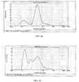
- FIG. 2b illustrate particle size distributions of a carbon black material (Vulcan XC-72R from Cabot) before and after treatment in a high shear mixer at room temperature (treatment time: 20 min; rotation speed: 6000 rpm; liquid medium: water/ethanol (weight ratio 200/1); weight ratio liquid medium : carbon black: 60 : 1)
- a carbon black material Vulcan XC-72R from Cabot
- the electrically conductive carbon material employed in the GDL (and also in the AL) can be amorphous or crystalline and preferably is or comprises a carbon black such as furnace black or acetylene black.
- the electrically conductive carbon material preferably has a BET surface area of at least about 250 m 2 /g, and usually not higher than about 1500 m 2 /g.
- Corresponding materials are commercially available.
- a non-limiting example of a commercially available material is carbon black Vulcan XC-72R from Cabot.
- the mixing temperatures in the process of the present invention will usually be ambient temperatures (from about 20°C to about 30°C), although lower and higher temperatures may be used as well, as long as the temperature does not exceed the boiling point of the liquid medium employed.
- the mixing will usually carried out in an open container under ambient pressure, although higher and lower pressures may be used as well.
- the polymeric binder for the AL may also be a mixture of one or more hydrophobic polymers and one or more hydrophilic polymers to adjust the hydrophilic/hydrophobic balance of the AL to an appropriate value (to provide a sufficiently stable three-phase boundary).
- suitable hydrophilic polymers for this purpose include polysulfones, perfluorosulfonate ionomers, and epoxy resins.
- the binders for in particular, the AL of the GDE of the present invention may be selected for use in combination that assures the proper hydrophobic/hydrophilic balance of the electrode, which provides the optimum ionic conduction pathways in the electrode.
- An additional advantage of this method is that the incorporation of polymeric materials into the structure can be carefully controlled. This provides the ability to tailor the hydrophobic/hydrophilic nature of the matrix to give improved performance characteristics.
- the electroactive catalyst for use in the AL of the GDE of the present invention may be selected from, e.g., the catalysts which are known to be suitable for use in a GDE.
- Non-limiting examples thereof include noble metal catalysts such as Pt, Pd, Ag, and alloys thereof (optionally supported on, e.g., carbon particles) and non-noble metal catalysts such as, e.g., spinels, perovskites, and macrocylic compounds such as Co-porphyrines, cobalt and iron phthalocyanines, tetra-aza annulene complexes, and tetraphenylporphyrine complexes of Co and Fe (optionally supported on, e.g., carbon particles).
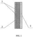
- the electrically conductive substrate may be placed on the gas side of the GDE, as is shown in FIG. 1 .
- the numeral 1 indicates the GDL (with current collector 2 embedded therein in a part thereof) and the numeral 3 indicates the AL.
- the conductive substrate may be selected from, e.g., the electrically conductive support structure that are known for this purpose and may, for example, be selected from, but not limited to, an electrically conductive mesh, a grid, a metal foam, an expanded metal, and any combinations thereof.
- a preferred electrically conductive substrate for use in the GDE of the present invention is an electrically conductive mesh having about 40 wires per inch horizontally and about 20 wires per inch vertically, although other mesh structures may work equally well.
- the wires constituting the mesh may have a diameter of from about 0.005 inches to about 0.01 inches, preferably from 0.005 inches to 0.008 inches. This design provides optimal current distribution due to the reduction of the ohmic resistance. If more than 20 vertical wires per inch are present, problems may be encountered when affixing the GDL material to the electrically conductive substrate.
- the electrically conductive substrate may be made of any electrically conductive material and is preferably made of a metallic material such as pure metal or a metal alloy. For example, if the GDL assures sufficiently dry conditions (keeping liquid electrolyte from reaching the gas side of the GDL) inexpensive materials such as copper gauze covered by Pb or conductive organics may be used.
- the GDL of the GDE obtained by the process of the present invention preferably has an average pore size of from about 7 nm to about 9 nm and thus makes it possible to achieve more than about 50 % of Knudsen diffusion.
- the GDL preferably has a thickness of not more than about 0.75 mm, e.g., from about 0.3 mm to about 0.7 mm. In combination with the pore size this provides a high rate of gas supply to the AL and makes the GDL stable enough against leaking of electrolyte.
- the AL of the GDE obtained by the process of the present invention preferably has a thickness of not more than about 0.3 mm, e.g., a thickness of from about 0.05 mm to about 0.1 mm. Due to the obtained intimate and homogeneous contact between catalytic particles and binder if the process of the present invention is used for producing the AL of the GDE, a lower amount of binder is needed and a thinner AL can be achieved, ensuring a high gas diffusion rate, high electronic conductivity and good ion transport in the liquid phase.
- the total thickness of the GDE of the present invention preferably is not higher than about 0.85 mm, and may be as low as about 0.5 mm.
- a further advantage of this GDE is improved performance due to reduced mass transport losses.
- the specific catalyst density of a GDE of the present invention usually will be from about 0.8 mg/cm 3 to about 50 mg/cm 3 or from about 0.1 mg/cm 2 to about 20 mg/cm 2 , and the overall density of the GDE usually will be from about 50 mg/cm 2 to about 150 mg/cm 2 .
- the GDE of the present invention may be made by procedures that are well known to those of skill in the art.
- the mass for the GDL may be spread on the electrically conductive substrate (current collector). This may be done by wet or dry technology, such as printing, rolling, K-bar or doctor blade methods or by spraying, etc.
- the basic structure of a GDE as shown in FIG. 1 , is obtained.
- the final step may include rolling and/or pressing of the entire structure, preferably at an elevated temperature up to about 320°C.
- a major advantage of the process of the present invention is that a dimensionally stable and highly flexible GDE can be obtained.
- the incidence of damage to the electrode on handling during manufacture is therefore minimized, thereby reducing the number of faulty or rejected electrodes, and consequently the manufacturing costs.
- the intrinsic material cost is significantly reduced.
- the electrode of the present invention is more amenable to high volume continuous production processes due to its high dimensional stability.
- GDEs of the present invention are suitable for low cost manufacture. They may be prepared by every known wet or dry technology, such as printing, rolling, K-bar or doctor blade methods or spraying, etc., as well as by continuous manufacturing processes, for example paper-making, calendaring or extrusion.
- a GDE according to the present invention for use as a cathode in an AFC was prepared as follows.
- a mass for the production of the GDL was prepared by using a self-made high shear mixer (500 - 10,000 rpm) with a 40 L reservoir.
- 200 g of carbon black (Vulcan XC-72R) was suspended and ground in 34 L of deionized water inside the reservoir for about 20 minutes, using a mixer speed of 8,000 rpm. 317 g of PTFE suspension (63 wt.
- % PTFE available from DuPont
- deionized water was diluted with deionized water to a total volume of 2 L, added to the reservoir containing water and previously treated carbon black and thereafter was subjected to high shear mixing at a rotation speed of 2,000 rpm for 30 minutes, followed by filtration and drying at 90°C for 4 hours.
- the obtained material (teflonized carbon black) was rolled at room temperature onto a current collector (Cu mesh covered by conductive organics) through a gap of 350 - 400 ⁇ m up to a thickness of 700 ⁇ 20 ⁇ m, thus preparing the GDL.
- the density of teflonized carbon black in the GDL was 60 mg/cm 2 .
- the mass for the production of the AL of the GDE was prepared by using the above high shear mixer with 40 L reservoir. First, 200 g of carbon black (Vulcan XC-72R) was suspended and ground in 34 L of deionized water inside the reservoir for about 20 minutes, using a mixer speed of 8,000 rpm. 200 g of catalyst (Ag/CoTMPP/carbon) was added to and suspended in the water + carbon mixture at 8,000 rpm for 20 minutes, followed by the addition of 70 g of PTFE suspension (63 wt. % PTFE, available from DuPont) that had been diluted with deionized water to a volume of 1 L, and subjecting the resultant mixture to high shear mixing for 30 minutes at 2,000 rpm.
- PTFE suspension 63 wt. % PTFE, available from DuPont
- the produced catalytic mass was rolled at room temperature through a gap of 200 ⁇ 10 ⁇ m up to thickness of the AL of 300 ⁇ 10 ⁇ m.
- the density of the catalytic mass in the AL was 25 mg/cm 2 .
- the GDL and AL prepared as described above were cut into pieces of desired size and then combined, with the AL on the side of the GDL opposite to that of the current collector.
- This sandwich structure was rolled consecutively through decreasing gaps from 900 ⁇ m down to 500 ⁇ 20 ⁇ m.
- the temperature of the rollers was 305 ⁇ 10°C.
- the final thickness of the GDE was 800 ⁇ 20 ⁇ m.
- the produced GDE showed very stable performance with a low overpotential, as illustrated in FIG. 3 .
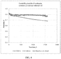
- the GDE was prepared in the same way as described in Example 1, but replacing the catalyst by CoTMPP/carbon.
- the performance of the resultant electrode is graphically represented in FIG. 4 .
Claims (13)
- Verfahren zur Herstellung einer Gasdiffusionselektrode, die ein elektrisch leitendes Substrat (2), eine Gasdiffusionsschicht, GDL, (1) und eine aktive Schicht, AL, (3) umfasst, wobei die GDL (1) mindestens ein erstes elektrisch leitendes Kohlenstoffmaterial und Polytetrafluorethylen als erstes polymeres Bindemittel umfasst und die AL (3) mindestens ein zweites elektrisch leitendes Kohlenstoffmaterial, Polytetrafluorethylen als zweites polymeres Bindemittel und elektroaktiven Katalysator umfasst, wobei das Verfahren das Bilden von sowohl der GDL (1) als auch der AL (3) durch mindestens eines von Pressen und Walzen einer Masse umfasst, die erhalten wird durch Unterwerfen von elektrisch leitendem Kohlenstoffmaterial und polymerem Bindemittel oder elektrisch leitendem Kohlenstoffmaterial, polymerem Bindemittel und elektroaktivem Katalysator in einem Gewichtsverhältnis elektrisch leitendes Kohlenstoffmaterial : polymeres Bindemittel von 0,75:1 bis 2,5:1 im Fall der GDL (1) und in einem Gewichtsverhältnis elektrisch leitendes Kohlenstoffmaterial : polymeres Bindemittel von 1:1 bis 5:1 im Fall der AL (3), ausgenommen des Kohlenstoffs, der als elektroaktiver Katalysator oder als Träger für einen elektroaktiven Katalysator in der AL (3) vorhanden sein kann, einem Mischen mit hoher Scherung in einem flüssigen Medium, gefolgt von der Abtrennung von Feststoff vom flüssigen Medium und gegebenenfalls Trocknen von abgetrenntem Feststoff.
- Verfahren nach Anspruch 1, wobei der abgetrennte Feststoff getrocknet wird.
- Verfahren nach einem der Ansprüche 1 und 2, wobei das gleiche elektrisch leitende Kohlenstoffmaterial in der GDL (1) und der AL (3) verwendet wird.
- Verfahren nach einem der Ansprüche 1 bis 3, wobei ein Gewichtsverhältnis flüssiges Medium : (elektrisch leitendes Kohlenstoffmaterial + polymeres Bindemittel) 200:1 bis 50:1 beträgt.
- Verfahren nach einem der Ansprüche 1 bis 4, wobei das Mischen für einen Zeitraum von mindestens etwa 10 Minuten durchgeführt wird.
- Verfahren nach einem der Ansprüche 1 bis 5, wobei das elektrisch leitende Kohlenstoffmaterial einem Mischen in mindestens einem Teil des flüssigen Mediums für einen ersten Zeitraum unterworfen wird, um eine mittlere Teilchengröße des elektrisch leitenden Kohlenstoffmaterials zu verringern, und danach mit dem polymeren Bindemittel kombiniert und einem Mischen mit hoher Scherung für einen zweiten Zeitraum unterworfen wird.
- Verfahren nach einem der Ansprüche 1 bis 6, wobei die GDL (1) eine mittlere Porengröße von 7 nm bis 9 nm aufweist.
- Verfahren nach einem der Ansprüche 1 bis 7, wobei die GDL (1) eine Dicke von nicht mehr als 0,75 mm aufweist.
- Verfahren nach einem der Ansprüche 1 bis 8, wobei die AL (3) eine Dicke von nicht mehr als 0,3 mm aufweist.
- Verfahren nach einem der Ansprüche 1 bis 9, wobei die kombinierte Dicke von GDL (1) und AL (3) nicht mehr als 0,85 mm beträgt.
- Gasdiffusionselektrode, die nach dem Verfahren nach einem der Ansprüche 1 bis 10 erhältlich ist.
- Brennstoffzelle, wobei die Brennstoffzelle die Gasdiffusionselektrode nach Anspruch 11 umfasst.
- Verfahren zur Erzeugung elektrischer Energie, wobei das Verfahren das Zuführen von Wasserstoff und Sauerstoff zur Brennstoffzelle nach Anspruch 12 und das Anlegen einer Last umfasst.
Applications Claiming Priority (2)
| Application Number | Priority Date | Filing Date | Title |
|---|---|---|---|
| US201361837319P | 2013-06-20 | 2013-06-20 | |
| PCT/US2014/043248 WO2014205259A1 (en) | 2013-06-20 | 2014-06-19 | Gas diffusion electrode and process for making same |
Publications (3)
| Publication Number | Publication Date |
|---|---|
| EP3011625A1 EP3011625A1 (de) | 2016-04-27 |
| EP3011625A4 EP3011625A4 (de) | 2016-11-30 |
| EP3011625B1 true EP3011625B1 (de) | 2021-05-05 |
Family
ID=52105304
Family Applications (1)
| Application Number | Title | Priority Date | Filing Date |
|---|---|---|---|
| EP14813603.9A Active EP3011625B1 (de) | 2013-06-20 | 2014-06-19 | Gasdiffusionselektrode und verfahren zur herstellung davon |
Country Status (4)
| Country | Link |
|---|---|
| US (1) | US9966609B2 (de) |
| EP (1) | EP3011625B1 (de) |
| IL (1) | IL243217B (de) |
| WO (1) | WO2014205259A1 (de) |
Cited By (1)
| Publication number | Priority date | Publication date | Assignee | Title |
|---|---|---|---|---|
| EP4343898A1 (de) | 2022-09-21 | 2024-03-27 | iGas energy GmbH | Kombination von poröser transportschicht und bipolarplatte für elektrochemische zellen |
Citations (1)
| Publication number | Priority date | Publication date | Assignee | Title |
|---|---|---|---|---|
| US5895542A (en) * | 1994-11-23 | 1999-04-20 | Appleton Papers Incorporated | Coater and a method for coating a substrate |
Family Cites Families (20)
| Publication number | Priority date | Publication date | Assignee | Title |
|---|---|---|---|---|
| US3537906A (en) | 1966-01-05 | 1970-11-03 | Allis Chalmers Mfg Co | Process for producing a fuel cell electrode |
| US4031033A (en) | 1971-03-29 | 1977-06-21 | Zlehit Pri Ban | Method for producing powdered wetproofed material useful in making gas-diffusion electrodes |
| US4179359A (en) | 1975-11-14 | 1979-12-18 | Uop Inc. | Hydrocarbon conversion with an acidic multimetallic catalytic composite |
| NL8006774A (nl) | 1980-12-13 | 1982-07-01 | Electrochem Energieconversie | Brandstofcelelectrode en werkwijze voor het vervaardigen van een brandstofcelelectrode. |
| US5110693A (en) | 1989-09-28 | 1992-05-05 | Hyperion Catalysis International | Electrochemical cell |
| US5480735A (en) | 1990-06-25 | 1996-01-02 | International Fuel Cells Corporation | High current alkaline fuel cell electrodes |
| IL116376A (en) * | 1994-12-15 | 2001-03-19 | Cabot Corp | Aqueous ink jet ink compositions containing modified carbon products |
| DE69709784T2 (de) | 1996-02-28 | 2002-08-08 | Johnson Matthey Plc | Verwendung von katalytisch aktiven Gasdiffusionselektroden mit Faservliessubstrat in einer Direkt-Methanol-Brennstoffzelle |
| US6103077A (en) | 1998-01-02 | 2000-08-15 | De Nora S.P.A. | Structures and methods of manufacture for gas diffusion electrodes and electrode components |
| US6517962B1 (en) * | 1999-08-23 | 2003-02-11 | Ballard Power Systems Inc. | Fuel cell anode structures for voltage reversal tolerance |
| US6280871B1 (en) * | 1999-10-12 | 2001-08-28 | Cabot Corporation | Gas diffusion electrodes containing modified carbon products |
| WO2001080342A1 (en) | 2000-04-17 | 2001-10-25 | Johnson Matthey Pulic Limited Company | Gas diffusion substrate |
| AU2001279308A1 (en) | 2000-07-25 | 2002-02-05 | Apollo Energy Systems, Incorporated | Electrodes for alkaline fuel cells with circulating electrolyte |
| JP2003006963A (ja) | 2001-06-26 | 2003-01-10 | Sony Corp | 記録再生装置 |
| US20030134178A1 (en) * | 2001-12-21 | 2003-07-17 | 3M Innovative Properties Company | Precompressed gas diffusion layers for electrochemical cells |
| KR101037592B1 (ko) * | 2002-06-14 | 2011-05-27 | 하이페리온 커탤리시스 인터내셔널 인코포레이티드 | 전기전도성 탄소 원섬유계 잉크 및 코팅 |
| US6977135B2 (en) | 2003-07-10 | 2005-12-20 | Marc David Levenson | Photosensitive material for immersion photolithography |
| US7259126B2 (en) | 2004-03-11 | 2007-08-21 | Ceramatec, Inc. | Gas diffusion electrode and catalyst for electrochemical oxygen reduction and method of dispersing the catalyst |
| US7629071B2 (en) | 2004-09-29 | 2009-12-08 | Giner Electrochemical Systems, Llc | Gas diffusion electrode and method of making the same |
| WO2009151013A1 (ja) | 2008-06-09 | 2009-12-17 | 旭硝子株式会社 | 固体高分子形燃料電池用膜電極接合体 |
-
2014
- 2014-06-19 EP EP14813603.9A patent/EP3011625B1/de active Active
- 2014-06-19 US US14/898,707 patent/US9966609B2/en active Active
- 2014-06-19 WO PCT/US2014/043248 patent/WO2014205259A1/en active Application Filing
-
2015
- 2015-12-17 IL IL243217A patent/IL243217B/en active IP Right Grant
Patent Citations (1)
| Publication number | Priority date | Publication date | Assignee | Title |
|---|---|---|---|---|
| US5895542A (en) * | 1994-11-23 | 1999-04-20 | Appleton Papers Incorporated | Coater and a method for coating a substrate |
Cited By (1)
| Publication number | Priority date | Publication date | Assignee | Title |
|---|---|---|---|---|
| EP4343898A1 (de) | 2022-09-21 | 2024-03-27 | iGas energy GmbH | Kombination von poröser transportschicht und bipolarplatte für elektrochemische zellen |
Also Published As
| Publication number | Publication date |
|---|---|
| US20160141629A1 (en) | 2016-05-19 |
| IL243217B (en) | 2019-02-28 |
| WO2014205259A1 (en) | 2014-12-24 |
| EP3011625A4 (de) | 2016-11-30 |
| US9966609B2 (en) | 2018-05-08 |
| EP3011625A1 (de) | 2016-04-27 |
Similar Documents
| Publication | Publication Date | Title |
|---|---|---|
| JP4629699B2 (ja) | 担持触媒とその製造方法、これを利用した電極及び燃料電池 | |
| JP5055788B2 (ja) | 電極触媒 | |
| JP5332429B2 (ja) | 電極触媒 | |
| EP3467922A1 (de) | Kohlenstoffträger | |
| EP2031683A1 (de) | Elektrodenmaterial | |
| JP6793136B2 (ja) | 電極触媒 | |
| CN108475791B (zh) | 催化剂 | |
| CA2677837C (en) | Method for the electrochemical deposition of catalyst particles onto carbon fibre-containing substrates and apparatus therefor | |
| EP3734728A1 (de) | Katalysator, herstellungsverfahren dafür, elektrode damit, membran-elektroden-anordnung und brennstoffzelle | |
| EP2634850B1 (de) | Verbundstoff, Katalysator damit, Brennstoffzelle und Lithium-Luftbatterie damit | |
| CN106415905B (zh) | 膜电极组件 | |
| KR20190009805A (ko) | 촉매 | |
| JP2008186798A (ja) | 電解質膜−電極接合体 | |
| US20150207153A1 (en) | Process for preparing a catalytic material | |
| KR20190129746A (ko) | 연료 전지용 촉매층 및 그 제조 방법 | |
| JP2009026501A (ja) | 電解質膜−電極接合体 | |
| JP2007188768A (ja) | 固体高分子型燃料電池 | |
| KR20140103178A (ko) | 연료 전지 | |
| EP3011625B1 (de) | Gasdiffusionselektrode und verfahren zur herstellung davon | |
| AU2022315863A1 (en) | Oxygen evolution reaction catalyst | |
| JP2005183263A (ja) | 多孔質構造体 | |
| JP2008047472A (ja) | 電極触媒 | |
| JP2008140703A (ja) | 電池用組成物およびそれを含む膜 | |
| JP2006086037A (ja) | 燃料電池用電極触媒、および、これを用いた燃料電池用電極触媒層 | |
| JP7303805B2 (ja) | 触媒 |
Legal Events
| Date | Code | Title | Description |
|---|---|---|---|
| PUAI | Public reference made under article 153(3) epc to a published international application that has entered the european phase |
Free format text: ORIGINAL CODE: 0009012 |
|
| 17P | Request for examination filed |
Effective date: 20151209 |
|
| AK | Designated contracting states |
Kind code of ref document: A1 Designated state(s): AL AT BE BG CH CY CZ DE DK EE ES FI FR GB GR HR HU IE IS IT LI LT LU LV MC MK MT NL NO PL PT RO RS SE SI SK SM TR |
|
| AX | Request for extension of the european patent |
Extension state: BA ME |
|
| DAX | Request for extension of the european patent (deleted) | ||
| A4 | Supplementary search report drawn up and despatched |
Effective date: 20161028 |
|
| RIC1 | Information provided on ipc code assigned before grant |
Ipc: H01M 8/0234 20160101ALI20161024BHEP Ipc: H01M 8/023 20160101ALI20161024BHEP Ipc: H01M 4/86 20060101AFI20161024BHEP Ipc: H01M 8/083 20160101ALI20161024BHEP Ipc: H01M 4/88 20060101ALI20161024BHEP |
|
| STAA | Information on the status of an ep patent application or granted ep patent |
Free format text: STATUS: EXAMINATION IS IN PROGRESS |
|
| 17Q | First examination report despatched |
Effective date: 20171027 |
|
| GRAP | Despatch of communication of intention to grant a patent |
Free format text: ORIGINAL CODE: EPIDOSNIGR1 |
|
| STAA | Information on the status of an ep patent application or granted ep patent |
Free format text: STATUS: GRANT OF PATENT IS INTENDED |
|
| INTG | Intention to grant announced |
Effective date: 20201119 |
|
| GRAS | Grant fee paid |
Free format text: ORIGINAL CODE: EPIDOSNIGR3 |
|
| GRAA | (expected) grant |
Free format text: ORIGINAL CODE: 0009210 |
|
| STAA | Information on the status of an ep patent application or granted ep patent |
Free format text: STATUS: THE PATENT HAS BEEN GRANTED |
|
| AK | Designated contracting states |
Kind code of ref document: B1 Designated state(s): AL AT BE BG CH CY CZ DE DK EE ES FI FR GB GR HR HU IE IS IT LI LT LU LV MC MK MT NL NO PL PT RO RS SE SI SK SM TR |
|
| REG | Reference to a national code |
Ref country code: GB Ref legal event code: FG4D |
|
| REG | Reference to a national code |
Ref country code: CH Ref legal event code: EP |
|
| REG | Reference to a national code |
Ref country code: AT Ref legal event code: REF Ref document number: 1390954 Country of ref document: AT Kind code of ref document: T Effective date: 20210515 |
|
| REG | Reference to a national code |
Ref country code: IE Ref legal event code: FG4D |
|
| REG | Reference to a national code |
Ref country code: DE Ref legal event code: R096 Ref document number: 602014077252 Country of ref document: DE |
|
| REG | Reference to a national code |
Ref country code: LT Ref legal event code: MG9D |
|
| REG | Reference to a national code |
Ref country code: AT Ref legal event code: MK05 Ref document number: 1390954 Country of ref document: AT Kind code of ref document: T Effective date: 20210505 |
|
| PG25 | Lapsed in a contracting state [announced via postgrant information from national office to epo] |
Ref country code: LT Free format text: LAPSE BECAUSE OF FAILURE TO SUBMIT A TRANSLATION OF THE DESCRIPTION OR TO PAY THE FEE WITHIN THE PRESCRIBED TIME-LIMIT Effective date: 20210505 Ref country code: FI Free format text: LAPSE BECAUSE OF FAILURE TO SUBMIT A TRANSLATION OF THE DESCRIPTION OR TO PAY THE FEE WITHIN THE PRESCRIBED TIME-LIMIT Effective date: 20210505 Ref country code: BG Free format text: LAPSE BECAUSE OF FAILURE TO SUBMIT A TRANSLATION OF THE DESCRIPTION OR TO PAY THE FEE WITHIN THE PRESCRIBED TIME-LIMIT Effective date: 20210805 Ref country code: AT Free format text: LAPSE BECAUSE OF FAILURE TO SUBMIT A TRANSLATION OF THE DESCRIPTION OR TO PAY THE FEE WITHIN THE PRESCRIBED TIME-LIMIT Effective date: 20210505 Ref country code: HR Free format text: LAPSE BECAUSE OF FAILURE TO SUBMIT A TRANSLATION OF THE DESCRIPTION OR TO PAY THE FEE WITHIN THE PRESCRIBED TIME-LIMIT Effective date: 20210505 |
|
| PG25 | Lapsed in a contracting state [announced via postgrant information from national office to epo] |
Ref country code: GR Free format text: LAPSE BECAUSE OF FAILURE TO SUBMIT A TRANSLATION OF THE DESCRIPTION OR TO PAY THE FEE WITHIN THE PRESCRIBED TIME-LIMIT Effective date: 20210806 Ref country code: IS Free format text: LAPSE BECAUSE OF FAILURE TO SUBMIT A TRANSLATION OF THE DESCRIPTION OR TO PAY THE FEE WITHIN THE PRESCRIBED TIME-LIMIT Effective date: 20210905 Ref country code: LV Free format text: LAPSE BECAUSE OF FAILURE TO SUBMIT A TRANSLATION OF THE DESCRIPTION OR TO PAY THE FEE WITHIN THE PRESCRIBED TIME-LIMIT Effective date: 20210505 Ref country code: ES Free format text: LAPSE BECAUSE OF FAILURE TO SUBMIT A TRANSLATION OF THE DESCRIPTION OR TO PAY THE FEE WITHIN THE PRESCRIBED TIME-LIMIT Effective date: 20210505 Ref country code: NO Free format text: LAPSE BECAUSE OF FAILURE TO SUBMIT A TRANSLATION OF THE DESCRIPTION OR TO PAY THE FEE WITHIN THE PRESCRIBED TIME-LIMIT Effective date: 20210805 Ref country code: PL Free format text: LAPSE BECAUSE OF FAILURE TO SUBMIT A TRANSLATION OF THE DESCRIPTION OR TO PAY THE FEE WITHIN THE PRESCRIBED TIME-LIMIT Effective date: 20210505 Ref country code: PT Free format text: LAPSE BECAUSE OF FAILURE TO SUBMIT A TRANSLATION OF THE DESCRIPTION OR TO PAY THE FEE WITHIN THE PRESCRIBED TIME-LIMIT Effective date: 20210906 Ref country code: RS Free format text: LAPSE BECAUSE OF FAILURE TO SUBMIT A TRANSLATION OF THE DESCRIPTION OR TO PAY THE FEE WITHIN THE PRESCRIBED TIME-LIMIT Effective date: 20210505 Ref country code: SE Free format text: LAPSE BECAUSE OF FAILURE TO SUBMIT A TRANSLATION OF THE DESCRIPTION OR TO PAY THE FEE WITHIN THE PRESCRIBED TIME-LIMIT Effective date: 20210505 |
|
| REG | Reference to a national code |
Ref country code: NL Ref legal event code: MP Effective date: 20210505 |
|
| PG25 | Lapsed in a contracting state [announced via postgrant information from national office to epo] |
Ref country code: NL Free format text: LAPSE BECAUSE OF FAILURE TO SUBMIT A TRANSLATION OF THE DESCRIPTION OR TO PAY THE FEE WITHIN THE PRESCRIBED TIME-LIMIT Effective date: 20210505 |
|
| PG25 | Lapsed in a contracting state [announced via postgrant information from national office to epo] |
Ref country code: SK Free format text: LAPSE BECAUSE OF FAILURE TO SUBMIT A TRANSLATION OF THE DESCRIPTION OR TO PAY THE FEE WITHIN THE PRESCRIBED TIME-LIMIT Effective date: 20210505 Ref country code: SM Free format text: LAPSE BECAUSE OF FAILURE TO SUBMIT A TRANSLATION OF THE DESCRIPTION OR TO PAY THE FEE WITHIN THE PRESCRIBED TIME-LIMIT Effective date: 20210505 Ref country code: CZ Free format text: LAPSE BECAUSE OF FAILURE TO SUBMIT A TRANSLATION OF THE DESCRIPTION OR TO PAY THE FEE WITHIN THE PRESCRIBED TIME-LIMIT Effective date: 20210505 Ref country code: DK Free format text: LAPSE BECAUSE OF FAILURE TO SUBMIT A TRANSLATION OF THE DESCRIPTION OR TO PAY THE FEE WITHIN THE PRESCRIBED TIME-LIMIT Effective date: 20210505 Ref country code: EE Free format text: LAPSE BECAUSE OF FAILURE TO SUBMIT A TRANSLATION OF THE DESCRIPTION OR TO PAY THE FEE WITHIN THE PRESCRIBED TIME-LIMIT Effective date: 20210505 Ref country code: RO Free format text: LAPSE BECAUSE OF FAILURE TO SUBMIT A TRANSLATION OF THE DESCRIPTION OR TO PAY THE FEE WITHIN THE PRESCRIBED TIME-LIMIT Effective date: 20210505 |
|
| REG | Reference to a national code |
Ref country code: CH Ref legal event code: PL |
|
| REG | Reference to a national code |
Ref country code: DE Ref legal event code: R097 Ref document number: 602014077252 Country of ref document: DE |
|
| REG | Reference to a national code |
Ref country code: BE Ref legal event code: MM Effective date: 20210630 |
|
| PLBE | No opposition filed within time limit |
Free format text: ORIGINAL CODE: 0009261 |
|
| STAA | Information on the status of an ep patent application or granted ep patent |
Free format text: STATUS: NO OPPOSITION FILED WITHIN TIME LIMIT |
|
| PG25 | Lapsed in a contracting state [announced via postgrant information from national office to epo] |
Ref country code: MC Free format text: LAPSE BECAUSE OF FAILURE TO SUBMIT A TRANSLATION OF THE DESCRIPTION OR TO PAY THE FEE WITHIN THE PRESCRIBED TIME-LIMIT Effective date: 20210505 Ref country code: LU Free format text: LAPSE BECAUSE OF NON-PAYMENT OF DUE FEES Effective date: 20210619 |
|
| 26N | No opposition filed |
Effective date: 20220208 |
|
| PG25 | Lapsed in a contracting state [announced via postgrant information from national office to epo] |
Ref country code: LI Free format text: LAPSE BECAUSE OF NON-PAYMENT OF DUE FEES Effective date: 20210630 Ref country code: IE Free format text: LAPSE BECAUSE OF NON-PAYMENT OF DUE FEES Effective date: 20210619 Ref country code: CH Free format text: LAPSE BECAUSE OF NON-PAYMENT OF DUE FEES Effective date: 20210630 |
|
| PG25 | Lapsed in a contracting state [announced via postgrant information from national office to epo] |
Ref country code: IS Free format text: LAPSE BECAUSE OF FAILURE TO SUBMIT A TRANSLATION OF THE DESCRIPTION OR TO PAY THE FEE WITHIN THE PRESCRIBED TIME-LIMIT Effective date: 20210905 Ref country code: AL Free format text: LAPSE BECAUSE OF FAILURE TO SUBMIT A TRANSLATION OF THE DESCRIPTION OR TO PAY THE FEE WITHIN THE PRESCRIBED TIME-LIMIT Effective date: 20210505 |
|
| PG25 | Lapsed in a contracting state [announced via postgrant information from national office to epo] |
Ref country code: BE Free format text: LAPSE BECAUSE OF NON-PAYMENT OF DUE FEES Effective date: 20210630 |
|
| PG25 | Lapsed in a contracting state [announced via postgrant information from national office to epo] |
Ref country code: HU Free format text: LAPSE BECAUSE OF FAILURE TO SUBMIT A TRANSLATION OF THE DESCRIPTION OR TO PAY THE FEE WITHIN THE PRESCRIBED TIME-LIMIT; INVALID AB INITIO Effective date: 20140619 |
|
| PG25 | Lapsed in a contracting state [announced via postgrant information from national office to epo] |
Ref country code: CY Free format text: LAPSE BECAUSE OF FAILURE TO SUBMIT A TRANSLATION OF THE DESCRIPTION OR TO PAY THE FEE WITHIN THE PRESCRIBED TIME-LIMIT Effective date: 20210505 |
|
| PGFP | Annual fee paid to national office [announced via postgrant information from national office to epo] |
Ref country code: FR Payment date: 20230622 Year of fee payment: 10 Ref country code: DE Payment date: 20230629 Year of fee payment: 10 |
|
| PGFP | Annual fee paid to national office [announced via postgrant information from national office to epo] |
Ref country code: IT Payment date: 20230620 Year of fee payment: 10 Ref country code: GB Payment date: 20230620 Year of fee payment: 10 |
|
| PG25 | Lapsed in a contracting state [announced via postgrant information from national office to epo] |
Ref country code: MK Free format text: LAPSE BECAUSE OF FAILURE TO SUBMIT A TRANSLATION OF THE DESCRIPTION OR TO PAY THE FEE WITHIN THE PRESCRIBED TIME-LIMIT Effective date: 20210505 |