EP3009754B1 - Unité extérieure pour climatiseur et procédé de production pour unité extérieure pour climatiseur - Google Patents
Unité extérieure pour climatiseur et procédé de production pour unité extérieure pour climatiseur Download PDFInfo
- Publication number
- EP3009754B1 EP3009754B1 EP13886679.3A EP13886679A EP3009754B1 EP 3009754 B1 EP3009754 B1 EP 3009754B1 EP 13886679 A EP13886679 A EP 13886679A EP 3009754 B1 EP3009754 B1 EP 3009754B1
- Authority
- EP
- European Patent Office
- Prior art keywords
- bottom plate
- lowermost column
- column tube
- outdoor unit
- filling member
- Prior art date
- Legal status (The legal status is an assumption and is not a legal conclusion. Google has not performed a legal analysis and makes no representation as to the accuracy of the status listed.)
- Active
Links
Images

Classifications
-
- F—MECHANICAL ENGINEERING; LIGHTING; HEATING; WEAPONS; BLASTING
- F24—HEATING; RANGES; VENTILATING
- F24F—AIR-CONDITIONING; AIR-HUMIDIFICATION; VENTILATION; USE OF AIR CURRENTS FOR SCREENING
- F24F1/00—Room units for air-conditioning, e.g. separate or self-contained units or units receiving primary air from a central station
- F24F1/06—Separate outdoor units, e.g. outdoor unit to be linked to a separate room comprising a compressor and a heat exchanger
- F24F1/14—Heat exchangers specially adapted for separate outdoor units
- F24F1/16—Arrangement or mounting thereof
-
- F—MECHANICAL ENGINEERING; LIGHTING; HEATING; WEAPONS; BLASTING
- F24—HEATING; RANGES; VENTILATING
- F24F—AIR-CONDITIONING; AIR-HUMIDIFICATION; VENTILATION; USE OF AIR CURRENTS FOR SCREENING
- F24F1/00—Room units for air-conditioning, e.g. separate or self-contained units or units receiving primary air from a central station
- F24F1/06—Separate outdoor units, e.g. outdoor unit to be linked to a separate room comprising a compressor and a heat exchanger
- F24F1/46—Component arrangements in separate outdoor units
- F24F1/48—Component arrangements in separate outdoor units characterised by air airflow, e.g. inlet or outlet airflow
- F24F1/50—Component arrangements in separate outdoor units characterised by air airflow, e.g. inlet or outlet airflow with outlet air in upward direction
Definitions
- the present invention relates to an outdoor unit of an air-conditioning apparatus, and a method for manufacturing the same.
- a heat exchanger is disposed on a back surface and a side surface, and a fan is further disposed on an upper surface.
- fins for radiating heat transferred from circular tubes or flat tubes are vertically skewered to the circular tubes or the flat tubes through which refrigerant moves.
- a distance between the bottom plate and a tube disposed on a lowermost column (hereinafter, referred to as a "lowermost column tube”) among the tubes for allowing the refrigerant to flow into the heat exchanger is short.
- dew condensation water formed by condensing moisture containing air heat-exchanged by the heat exchanger sometimes stays between the lowermost column tube and the bottom plate.
- the staying dew condensation water causes the corrosion of the lowermost column tube. Additionally, when the staying dew condensation water is frozen, the volume of the dew condensation water is expanded, which causes the breakage and the damage of the lowermost column tube. Additionally, in a case where the lowermost column tube and the bottom plate are made of different kinds of materials, dissimilar metal corrosion (galvanic corrosion) is likely to be generated.
- connection tubes for supplying the refrigerant to the heat exchanger or connection tubes such as U-bend tubes for mutually connecting a plurality of the tubes of the heat exchanger are connected by brazing.
- the brazing parts sometimes swell compared to the diameters of the tubes, and a distance between the bottom plate and the tube is further reduced. Therefore, the above problem is more remarkable.
- an outlet is provided at a position, facing a lower surface of a heat exchanger, of a bottom plate, and dew condensation water from the heat exchanger is discharged from the outlet.
- an outlet is provided at a position, corresponding to a compressor, of a bottom plate, and a water passage having a gradient for guiding water toward the outlet is provided.
- Patent Literature 3 a plurality of louver-like cut-raised parts are provided at a position, corresponding to a heat exchanger, of a bottom plate, and dew condensation water is discharged.
- Patent Literature 4 discloses an outdoor unit of an air-conditioning apparatus according to the preamble of claim 1.
- the bottom plate is a member for supporting a structure such as the heat exchanger, and there is a problem that the strength of the bottom plate is lowered when the outlet is formed in the bottom plate.
- the plurality of louver-like cut-raised parts are provided in the bottom plate, and therefore the opening area of the bottom plate increases. Therefore, there is a problem that air flowing into the outdoor unit flows out from openings of the bottom plate, the air volume of air passing through the heat exchanger reduces, and heat exchange performance lowers. Additionally, the opening area of the bottom plate is large, and therefore there is a possibility that a small animal, snow, or the like are inclined to invade therein through the openings of the bottom plate.
- the heat exchanger In the outdoor unit of the air-conditioning apparatus, when the heat exchanger is disposed on the bottom plate, the heat exchanger is disposed at a desired position, and therefore a member for positioning the heat exchanger (positioning member) is required.
- a member for positioning the heat exchanger positioning member
- a claw is formed in a metal plate provided in the heat exchanger, and this claw is inserted into an opening of the bottom plate, so that the positioning of the heat exchanger is performed.
- a manufacturing cost increases due to provision of such a positioning member.
- the present invention has been made to solve the above problems, and a first object is to obtain an outdoor unit of an air-conditioning apparatus capable of making it difficult that dew condensation water stays between a lowermost column tube of a heat exchanger and a bottom plate, and a method for manufacturing an outdoor unit of an air-conditioning apparatus.
- a second object is to obtain an outdoor unit of an air-conditioning apparatus capable of preventing contact between the lowermost column tube of the heat exchanger and the bottom plate, and a method for manufacturing an outdoor unit of an air-conditioning apparatus.
- a third object is to obtain an outdoor unit of an air-conditioning apparatus capable of suppressing dissimilar metal corrosion, and a method for manufacturing an outdoor unit of an air-conditioning apparatus.
- a fourth object is to obtain an outdoor unit of an air-conditioning apparatus capable of suppressing increase in a manufacturing cost, and a method for manufacturing an outdoor unit of an air-conditioning apparatus.
- An outdoor unit of an air-conditioning apparatus according to the present invention is set forth in claim 1.
- a method for manufacturing an outdoor unit of an air-conditioning apparatus according to the present invention is set forth in claim 5.
- the present invention is capable of making it difficult that dew condensation water stays between a lowermost column tube of a heat exchanger and a bottom plate. Additionally, it is possible to prevent contact between the lowermost column tube of the heat exchanger and the bottom plate.
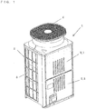
- Fig. 1 is a perspective view of an outdoor unit of an air-conditioning apparatus according to Embodiment 1 of the present invention.
- the outdoor unit 1 of the air-conditioning apparatus has a large oblong housing.
- air inlets 2 for taking air inside are provided in side surfaces and a back surface of the housing.
- the air inlets 2 are formed in three surfaces of the four side surfaces of the housing.
- a front upper panel 3_1 and a front lower panel 3_2 for opening and closing when the inside of the housing is maintained are provided.
- a heat exchanger 5 is disposed along the air inlets 2.
- air outlets 4 for blowing out air are provided in the upper surface of the housing.
- a fan is installed in the vicinity of the air outlets 4. When the fan rotates, air is sucked from the air inlets 2 to pass through the heat exchanger 5, and thereafter is blown out from the air outlets 4.
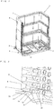
- Fig. 2 is a perspective view illustrating a state where the heat exchanger of the outdoor unit of the air-conditioning apparatus according to Embodiment 1 of the present invention is mounted on a bottom plate.
- Fig. 3 is an enlarged perspective view of a part A of Fig. 2.
- Fig. 3 illustrates a state where a gap filling member 15 described later is not mounted.
- the heat exchanger 5 is disposed on a bottom plate 6 made of, for example, iron.
- the heat exchanger 5 includes a plurality of radiation fins 8, and a plurality of heat transfer tubes 7.
- This heat exchanger 5 performs heat exchange between gas such as air that passes between the plurality of radiation fins 8, and the refrigerant that circulates inside the plurality of heat transfer tubes 7.
- the heat exchanger 5 is formed in, for example, a substantially U-shape, along the air inlets 2. The shape of the heat exchanger 5 is not limited to this.
- the radiation fins 8 each are made of, for example, aluminum, or an alloy containing aluminum, and each have a plate-like shape. A plurality of the radiation fins 8 are stacked at predetermined intervals, and gas such as air circulates between the radiation fins. Additionally, openings for inserting the plurality of heat transfer tubes 7 are formed in the radiation fins 8, and the heat transfer tubes 7 are inserted into the respective openings, so that the openings are joined to the plurality of heat transfer tubes 7.
- the plurality of heat transfer tubes 7 each are made of, for example, aluminum, or an alloy containing aluminum, and each are a heat transfer tube having a flat cross-sectional outline.
- the plurality of heat transfer tubes 7 are disposed at a plurality of columns in a column direction intersecting with an air circulating direction, and are disposed at a plurality of rows in a row direction along the air circulating direction.
- the heat transfer tubes 7 are disposed such that the direction of a long axis of each flat tube is parallel to the surface of the bottom plate 6.
- the direction of the long axis of each flat shape is the direction of the air circulating direction (row direction), and the plurality of heat transfer tubes 7 are disposed at intervals in a direction of a short axis of each flat shape (column direction).
- the heat transfer tubes 7 are connected to a plurality of tubes 10 for allowing the refrigerant to flow, at one end face 9 of the heat exchanger 5.
- the plurality of tubes 10 are made of, for example, aluminum, or an alloy containing aluminum.
- the tubes 10 are connected to the heat transfer tubes 7.
- the present invention is not limited to this, and the heat transfer tubes 7 and the tubes 10 may be integrally formed. That is, the heat transfer tubes 7 may extend beyond the end face 9 of the heat exchanger 5, and extending parts of the heat transfer tubes 7 may be formed as the tubes 10.
- the other end face side (right side of Fig. 2 ) of the heat exchanger 5 has a shape in which the heat transfer tubes 7 are each bent into a U-shape on an axial end side.
- the heat transfer tubes 7 are each bent into the U-shape herein, but the present invention is not limited to this.
- the axial ends of the heat transfer tubes 7 may be connected to the heat transfer tubes 7 disposed at other columns by using U-bend tubes or the like.
- Lead tubes 20 are connected to the plurality of tubes 10, respectively. These lead tubes 20 are made of, for example, aluminum, or an alloy containing aluminum. The lead tubes 20 each function as, for example, a joint for connecting the flat tube and the circular tube. The lead tubes 20 are connected to the tubes 10 by brazing 14. To these lead tubes 20, the U-bend tubes connected to the heat transfer tubes 7 disposed at other columns, distributors for distributing refrigerant, refrigerant tubes for connecting the heat exchanger 5 and other components, and the like are connected.
- the tube disposed at the lowermost column of the heat exchanger 5 (hereinafter, referred to as a "lowermost column tube 11 ") is located adjacent to the bottom plate 6.
- dew condensation water obtained by condensing moisture contained in heat-exchanged air sometimes stays in a gap 12 between the lowermost column tube 11 and the bottom plate 6.
- the staying dew condensation water causes corrosion of the lowermost column tube 11. Additionally, when the staying dew condensation water is frozen, the volume of the dew condensation water expands, which causes breakage and damage of the lowermost column tube 11.
- the area of a part located adjacent to the bottom plate 6 increases compared to a case of the circular tube. That is, the amount of dew condensation water staying between the flat lowermost column tube 11 and the bottom plate 6 increases. Accordingly, the corrosion of the lowermost column tube 11 is likely to be accelerated compared to the circular tube. Additionally, the frozen area of the dew condensation water increases, and a possibility that the lowermost column tube 11 is broken increases compared to the circular tube.
- the lowermost column tube 11 and the bottom plate 6 are made of different kinds of metals, the lowermost column tube 11 and the bottom plate 6 become conductive by the staying dew condensation water, and a potential difference occurs, which causes dissimilar metal corrosion.
- the lowermost column tube 11 and the lead tube 20 are connected by the brazing 14, and the brazing 14 swells beyond the tube diameter of the lowermost column tube 11. Therefore, the gap 12 between the brazing 14 and the bottom plate 6 further reduces. In a case where the lowermost column tube 11 is vibrated, the lowermost column tube 11 and the bottom plate 6 are likely to come into contact with each other.
- the outdoor unit 1 of the air-conditioning apparatus according to this Embodiment 1 is provided with the gap filling member 15 in the gap 12 between at least one of the lowermost column tube 11 and the lead tube 20 connected to the lowermost column tube 11, and the bottom plate 6.
- the gap filling member 15 will be described.
- the lowermost column tube 11 and the lead tube 20 connected to the lowermost column tube 11 are equivalent to a "lowermost column tube" of the present invention.
- Fig. 4 is a perspective view illustrating a state where the gap filling member is mounted on the lowermost column tube of the heat exchanger of the outdoor unit of the air-conditioning apparatus according to Embodiment 1 of the present invention.
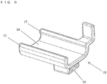
- Fig. 5 and Fig. 6 each are a perspective view of the gap filling member of the outdoor unit of the air-conditioning apparatus according to Embodiment 1 of the present invention.
- the gap filling member 15 is made of, for example, resin.
- the gap filling member 15 is provided in the gap between the lowermost column tube 11 and the bottom plate 6.
- the gap filling member 15 may be provided in a gap between the lead tube 20 connected to the lowermost column tube 11 and the bottom plate 6. Additionally, the gap filling member 15 may be provided in both the gap between the lowermost column tube 11 and the bottom plate 6, and the gap between the lead tube 20 connected to the lowermost column tube 11 and the bottom plate 6.
- the gap filling member 15 is provided in the gap between the lowermost column tube 11 and the bottom plate 6, so that it is possible to prevent dew condensation water from staying in the gap. Additionally, in a case where the lowermost column tube 11 is vibrated by the vibration during the operation or the conveyance of the outdoor unit 1, the gap filling member 15 functions as a buffer material, and can prevent contact between the lowermost column tube 11 and the bottom plate 6.
- the material of the gap filling member 15 is not limited to resin.
- the gap filling member 15 may be made of rubber.
- the gap filling member 15 is made of a material having an insulating property, so that the lowermost column tube 11 and the bottom plate 6 can be insulated, and dissimilar metal corrosion can be suppressed. Additionally, the gap filling member 15 is made of a material having elasticity, so that it is possible to suppress vibration of the lowermost column tube 11.
- the gap filling member 15 is formed with a recess 18 having a U-shaped cross-section. Returning parts 17 that form both side surfaces of the recess 18 are formed such that a width between upper parts is narrow corresponding to the shape of the lowermost column tube 11. When the lowermost column tube 11 is fitted in the recess 18 of the gap filling member 15, the gap filling member 15 holds the lowermost column tube 11 to be fixed by the returning parts 17.
- a fixing method of the gap filling member 15 is not limited to this.
- a width between the returning parts 17 forming the both side surfaces of the recess 18 may be made to be slightly narrower than the outline of the lowermost column tube 11, and the lowermost column tube 11 may be held by elastic force of the returning parts 17.
- a cylindrical part having a flat cross-section may be formed in place of the recess 18, and an end of the lowermost column tube 11 may be inserted into the cylindrical part of the gap filling member 15, so that the gap filling member 15 may be fixed to the lowermost column tube 11.
- the gap filling member 15 has a structure in which the gap filling member 15 can be fixed to the lowermost column tube 11 without using any tool.
- the gap filling member 15 is formed with a protrusion 16 on a side close to the bottom plate 6.
- the protrusion 16 has a shape corresponding to the opening 19 (see Fig. 3 ) formed at a position, facing the gap filling member 15, of the bottom plate 6.
- the opening 19 of the bottom plate 6 is formed in, for example, a quadrangle.
- the protrusion 16 of the gap filling member 15 is formed in a cube corresponding to the opening 19.
- the shapes of the opening 19 and the protrusion 16 are not limited to the above.
- the opening 19 may be formed in a circle, and the protrusion 16 may be formed in a columnar.
- the opening 19 may be formed in a circle, and the protrusion 16 may be formed in a columnar.
- each shape may be an arbitrary shape such as a trapezoid. That is, the shapes of the opening 19 and the protrusion 16 may be arbitrary shapes as long as the shapes can be satisfactorily used for positioning.
- the gap filling member 15 has a structure as a member for positioning when the heat exchanger 5 is disposed on the bottom plate 6.
- the method for manufacturing the outdoor unit 1 of the air-conditioning apparatus includes at least the following steps.
- the gap filling member 15 is fitted to at least one of the lowermost column tube 11, and the lead tube 20 connected to the lowermost column tube 11 to be fixed.
- the protrusion 16 of the gap filling member 15 is fitted in the opening 19 of the bottom plate 6, so that positioning of the heat exchanger 5 on the bottom plate 6 is implemented.
- the gap filling member 15 functions as a member for positioning when the heat exchanger 5 is disposed on the bottom plate 6. Accordingly, the member for positioning does not need to be separately provided, and a manufacturing cost can be suppressed.
- the gap filling member 15 is provided in the gap between the lowermost column tube 11 and the bottom plate 6.
- the gap filling member 15 is formed with the recess 18 having the U-shaped cross-section, and the lowermost column tube 11 is fitted in the recess 18 to be fixed.
- the gap filling member 15 can be fixed to the lowermost column tube 11 without using any tool. Accordingly, it is possible to suppress increase in a manufacturing cost.
- the bottom plate 6 is formed with the opening 19 at the position facing the gap filling member 15, and the gap filling member 15 is formed with the protrusion 16 fitted in the opening 19, on the side close to the bottom plate 6.
- the gap filling member 15 functions as the member for positioning when the heat exchanger 5 is disposed on the bottom plate 6. Accordingly, the member for positioning does not need to be separately provided, and a manufacturing cost can be suppressed.
- the gap filling member 15 is a material having an insulating property.
- the lowermost column tube 11 and the bottom plate 6 can be insulated. Even when the lowermost column tube 11 and the bottom plate 6 are made of different kinds of metals, it is possible to suppress dissimilar metal corrosion.
- the lowermost column tube 11 is a flat tube, and is disposed such that the direction of the long axis of the flat tube is parallel to the surface of the bottom plate 6.
- the gap filling member 15 is provided in the gap between the lowermost column tube 11 and the bottom plate 6, and therefore it is possible to make it difficult that dew condensation water from the heat exchanger 5 stays. Accordingly, it is possible to prevent the corrosion, the breakage, and the damage of the lowermost column tube 11.
Landscapes
- Engineering & Computer Science (AREA)
- Chemical & Material Sciences (AREA)
- Combustion & Propulsion (AREA)
- Mechanical Engineering (AREA)
- General Engineering & Computer Science (AREA)
- Other Air-Conditioning Systems (AREA)
- Heat-Exchange Devices With Radiators And Conduit Assemblies (AREA)
Claims (5)
- Unité extérieure d'un dispositif de climatisation, comprenant :un échangeur de chaleur (5) ayant une pluralité de tubes (10) ;une plaque inférieure (6) agencée sous l'échangeur de chaleur (5) ; etun élément de remplissage d'espace (15) agencé dans un espace entre un tube de colonne le plus inférieur (11) disposé à une extrémité inférieure de l'échangeur de chaleur (5), parmi la pluralité de tubes (10), et la plaque inférieure (6), et caractérisée en ce quele tube de colonne le plus inférieur (11) est un tube plat,le tube de colonne le plus inférieur (11) est disposé de telle sorte qu'une direction d'un axe longitudinal en coupe transversale du tube plat est parallèle à une surface de la plaque inférieure (6),l'élément de remplissage d'espace (15) est muni d'un évidement (18) ayant une coupe transversale en forme de U,l'évidement (18) est muni de parties de retour (17) sur ses deux surfaces latérales, une largeur entre des parties supérieures des parties de retour (17) est plus étroite qu'une largeur de l'axe longitudinal en coupe transversale du tube de colonne le plus inférieur (11), etles parties de retour (17) maintiennent le tube de colonne le plus inférieur (11), et le tube de colonne le plus inférieur (11) est agencé dans l'évidement (18).
- Unité extérieure d'un dispositif de climatisation selon la revendication 1, dans laquelle
la plaque inférieure (6) est munie d'une ouverture (19) dans une position faisant face à l'élément de remplissage d'espace (15), et
l'élément de remplissage d'espace (15) est muni d'une saillie (16) agencée dans l'ouverture (19), sur un côté proche de la plaque inférieure (6). - Unité extérieure d'un dispositif de climatisation selon la revendication 1 ou 2, dans laquelle
l'élément de remplissage d'espace (15) est constitué d'un matériau ayant une propriété isolante, et
le tube de colonne le plus inférieur (11) et la plaque inférieure (6) sont réalisés en des types de métaux différents. - Unité extérieure d'un dispositif de climatisation selon la revendication 3, dans laquelle
le tube de colonne le plus inférieur (11) est réalisé en aluminium, ou en un alliage contenant de l'aluminium, et
la plaque inférieure (6) est réalisée en fer. - Procédé de fabrication d'une unité extérieure d'un dispositif de climatisation selon la revendication 1, le procédé de fabrication de l'unité extérieure du dispositif de climatisation, dans lequel un tube de colonne le plus inférieur (11) est disposé de telle sorte qu'une direction d'un axe longitudinal en coupe transversal du tube plat est parallèle à une surface de la plaque inférieure (6), comprenant les étapes consistant à :raccorder un élément de remplissage d'espace (15) à un tube de colonne le plus inférieur (11) en maintenant le tube de colonne le plus inférieur (11) avec des parties de retour (17) pour fixer l'élément de remplissage d'espace (15), l'élément de remplissage d'espace (15) étant formé avec un évidement (18) ayant une coupe transversale en forme de U, et étant formé de telle sorte que l'évidement (18) est formé avec les parties de retour (17) sur ses deux surfaces latérales, une largeur entre des parties supérieures des parties de retour (17) étant plus étroite qu'une largeur de l'axe longitudinal en coupe transversale du tube de colonne le plus inférieur (11) disposé à une extrémité inférieure de l'échangeur de chaleur (5) parmi la pluralité de tubes plats ; etraccorder une saillie (16) dans une ouverture (19) de la plaque inférieure (6) pour mettre en oeuvre un positionnement de l'échangeur de chaleur (5) sur la plaque inférieure (6), la saillie (16) étant formée sur un côté, proche de la plaque inférieure (6), de l'élément de remplissage d'espace (15).
Applications Claiming Priority (1)
| Application Number | Priority Date | Filing Date | Title |
|---|---|---|---|
| PCT/JP2013/066476 WO2014199514A1 (fr) | 2013-06-14 | 2013-06-14 | Unité extérieure pour climatiseur et procédé de production pour unité extérieure pour climatiseur |
Publications (3)
| Publication Number | Publication Date |
|---|---|
| EP3009754A1 EP3009754A1 (fr) | 2016-04-20 |
| EP3009754A4 EP3009754A4 (fr) | 2017-01-18 |
| EP3009754B1 true EP3009754B1 (fr) | 2017-10-25 |
Family
ID=52021844
Family Applications (1)
| Application Number | Title | Priority Date | Filing Date |
|---|---|---|---|
| EP13886679.3A Active EP3009754B1 (fr) | 2013-06-14 | 2013-06-14 | Unité extérieure pour climatiseur et procédé de production pour unité extérieure pour climatiseur |
Country Status (3)
| Country | Link |
|---|---|
| EP (1) | EP3009754B1 (fr) |
| JP (1) | JP5963958B2 (fr) |
| WO (1) | WO2014199514A1 (fr) |
Families Citing this family (2)
| Publication number | Priority date | Publication date | Assignee | Title |
|---|---|---|---|---|
| JP2021167676A (ja) | 2018-07-25 | 2021-10-21 | ダイキン工業株式会社 | 継手 |
| JP2020165644A (ja) * | 2019-03-29 | 2020-10-08 | ダイキン工業株式会社 | 熱交換器、熱交換器の製造方法及びヘッダアッセンブリの製造方法 |
Family Cites Families (16)
| Publication number | Priority date | Publication date | Assignee | Title |
|---|---|---|---|---|
| JPS5821792U (ja) * | 1981-08-05 | 1983-02-10 | 三菱電機株式会社 | 熱交換器の支持装置 |
| JPS6014426U (ja) * | 1983-07-08 | 1985-01-31 | 株式会社富士通ゼネラル | 空気調和機 |
| JPS60103298A (ja) * | 1983-11-10 | 1985-06-07 | Nippon Denso Co Ltd | 熱交換器取付具 |
| JPH0250033A (ja) * | 1988-08-06 | 1990-02-20 | Mitsubishi Electric Corp | 熱交換器の取付構造 |
| JPH0741327A (ja) | 1993-07-28 | 1995-02-10 | Matsushita Electric Ind Co Ltd | 光学素子成形方法 |
| JPH09145095A (ja) | 1995-11-20 | 1997-06-06 | Fujitsu General Ltd | 空気調和機の室外機 |
| JP3842903B2 (ja) * | 1998-07-27 | 2006-11-08 | 三菱重工業株式会社 | 室外ユニット及び空気調和機 |
| JP2004183906A (ja) * | 2002-11-29 | 2004-07-02 | Fujitsu General Ltd | 空気調和機 |
| KR100988572B1 (ko) * | 2003-08-14 | 2010-10-18 | 삼성전자주식회사 | 공기조화기의 실외기 |
| JP2007010269A (ja) | 2005-07-01 | 2007-01-18 | Sharp Corp | 空気調和機の室外機 |
| JP5305945B2 (ja) * | 2009-01-26 | 2013-10-02 | 三菱電機株式会社 | フィンチューブ式熱交換器の保持装置 |
| JP2011007364A (ja) * | 2009-06-23 | 2011-01-13 | Sanyo Electric Co Ltd | 空気調和機 |
| JP2011145029A (ja) * | 2010-01-18 | 2011-07-28 | Sharp Corp | 空気調和機 |
| JP5510383B2 (ja) | 2011-04-19 | 2014-06-04 | 三菱電機株式会社 | ヒートポンプ装置の熱源機、空気調和機の室外機 |
| CN102494370B (zh) * | 2011-11-28 | 2013-08-28 | 宁波奥克斯空调有限公司 | 用于相邻两排冷凝器的固定装置 |
| JP5464207B2 (ja) * | 2011-12-28 | 2014-04-09 | ダイキン工業株式会社 | 冷凍装置の室外ユニット |
-
2013
- 2013-06-14 EP EP13886679.3A patent/EP3009754B1/fr active Active
- 2013-06-14 JP JP2015522370A patent/JP5963958B2/ja active Active
- 2013-06-14 WO PCT/JP2013/066476 patent/WO2014199514A1/fr active Application Filing
Non-Patent Citations (1)
| Title |
|---|
| None * |
Also Published As
| Publication number | Publication date |
|---|---|
| EP3009754A1 (fr) | 2016-04-20 |
| WO2014199514A1 (fr) | 2014-12-18 |
| EP3009754A4 (fr) | 2017-01-18 |
| JPWO2014199514A1 (ja) | 2017-02-23 |
| JP5963958B2 (ja) | 2016-08-03 |
Similar Documents
| Publication | Publication Date | Title |
|---|---|---|
| EP2930456B1 (fr) | Appareil d'échange thermique à tubes plats, et unité extérieure pour climatiseur le comportant | |
| EP3279598B1 (fr) | Échangeur de chaleur et climatiseur | |
| EP2594886B1 (fr) | Échangeur de chaleur | |
| US10113756B2 (en) | Air-conditioning-apparatus outdoor unit and method of manufacturing air-conditioning-apparatus outdoor unit | |
| EP3650798B1 (fr) | Échangeur de chaleur | |
| US10465924B2 (en) | Heat exchanger | |
| AU2018242434B2 (en) | Heat exchanger and air conditioner | |
| EP3561430A2 (fr) | Échangeur de chaleur | |
| EP3009754B1 (fr) | Unité extérieure pour climatiseur et procédé de production pour unité extérieure pour climatiseur | |
| EP3644002A1 (fr) | Échangeur de chaleur, dispositif à cycle frigorifique et climatiseur | |
| US10605467B2 (en) | Outdoor unit for air-conditioning apparatus and method of producing outdoor unit for air-conditioning apparatus | |
| US11384991B2 (en) | Heat exchanger | |
| JP2018162953A (ja) | 熱交換器 | |
| CN108361819B (zh) | 一种连接管固定件、具有其的换热器及空调室内机 | |
| EP3550247A1 (fr) | Échangeur de chaleur et climatiseur | |
| EP3330637B1 (fr) | Échangeur de chaleur et appareil à cycle de réfrigération | |
| EP3832244A1 (fr) | Échangeur de chaleur, unité d'échangeur de chaleur et dispositif à cycle de réfrigération | |
| EP3574277B1 (fr) | Échangeur de chaleur | |
| CN110945300B (zh) | 制冷剂分配器、热交换器及制冷循环装置 | |
| KR20080060580A (ko) | 열교환기 | |
| KR20120048170A (ko) | 열교환기 |
Legal Events
| Date | Code | Title | Description |
|---|---|---|---|
| PUAI | Public reference made under article 153(3) epc to a published international application that has entered the european phase |
Free format text: ORIGINAL CODE: 0009012 |
|
| 17P | Request for examination filed |
Effective date: 20151006 |
|
| AK | Designated contracting states |
Kind code of ref document: A1 Designated state(s): AL AT BE BG CH CY CZ DE DK EE ES FI FR GB GR HR HU IE IS IT LI LT LU LV MC MK MT NL NO PL PT RO RS SE SI SK SM TR |
|
| AX | Request for extension of the european patent |
Extension state: BA ME |
|
| DAX | Request for extension of the european patent (deleted) | ||
| A4 | Supplementary search report drawn up and despatched |
Effective date: 20161219 |
|
| RIC1 | Information provided on ipc code assigned before grant |
Ipc: F24F 1/46 20110101ALI20161213BHEP Ipc: F24F 1/16 20110101AFI20161213BHEP Ipc: F24F 13/30 20060101ALI20161213BHEP Ipc: F24F 1/50 20110101ALI20161213BHEP |
|
| GRAP | Despatch of communication of intention to grant a patent |
Free format text: ORIGINAL CODE: EPIDOSNIGR1 |
|
| INTG | Intention to grant announced |
Effective date: 20170609 |
|
| GRAS | Grant fee paid |
Free format text: ORIGINAL CODE: EPIDOSNIGR3 |
|
| GRAA | (expected) grant |
Free format text: ORIGINAL CODE: 0009210 |
|
| AK | Designated contracting states |
Kind code of ref document: B1 Designated state(s): AL AT BE BG CH CY CZ DE DK EE ES FI FR GB GR HR HU IE IS IT LI LT LU LV MC MK MT NL NO PL PT RO RS SE SI SK SM TR |
|
| REG | Reference to a national code |
Ref country code: GB Ref legal event code: FG4D |
|
| REG | Reference to a national code |
Ref country code: CH Ref legal event code: EP |
|
| REG | Reference to a national code |
Ref country code: AT Ref legal event code: REF Ref document number: 940297 Country of ref document: AT Kind code of ref document: T Effective date: 20171115 |
|
| REG | Reference to a national code |
Ref country code: IE Ref legal event code: FG4D |
|
| REG | Reference to a national code |
Ref country code: DE Ref legal event code: R096 Ref document number: 602013028604 Country of ref document: DE |
|
| REG | Reference to a national code |
Ref country code: NL Ref legal event code: MP Effective date: 20171025 |
|
| REG | Reference to a national code |
Ref country code: LT Ref legal event code: MG4D |
|
| REG | Reference to a national code |
Ref country code: AT Ref legal event code: MK05 Ref document number: 940297 Country of ref document: AT Kind code of ref document: T Effective date: 20171025 |
|
| PG25 | Lapsed in a contracting state [announced via postgrant information from national office to epo] |
Ref country code: NL Free format text: LAPSE BECAUSE OF FAILURE TO SUBMIT A TRANSLATION OF THE DESCRIPTION OR TO PAY THE FEE WITHIN THE PRESCRIBED TIME-LIMIT Effective date: 20171025 |
|
| PG25 | Lapsed in a contracting state [announced via postgrant information from national office to epo] |
Ref country code: FI Free format text: LAPSE BECAUSE OF FAILURE TO SUBMIT A TRANSLATION OF THE DESCRIPTION OR TO PAY THE FEE WITHIN THE PRESCRIBED TIME-LIMIT Effective date: 20171025 Ref country code: LT Free format text: LAPSE BECAUSE OF FAILURE TO SUBMIT A TRANSLATION OF THE DESCRIPTION OR TO PAY THE FEE WITHIN THE PRESCRIBED TIME-LIMIT Effective date: 20171025 Ref country code: SE Free format text: LAPSE BECAUSE OF FAILURE TO SUBMIT A TRANSLATION OF THE DESCRIPTION OR TO PAY THE FEE WITHIN THE PRESCRIBED TIME-LIMIT Effective date: 20171025 Ref country code: ES Free format text: LAPSE BECAUSE OF FAILURE TO SUBMIT A TRANSLATION OF THE DESCRIPTION OR TO PAY THE FEE WITHIN THE PRESCRIBED TIME-LIMIT Effective date: 20171025 Ref country code: NO Free format text: LAPSE BECAUSE OF FAILURE TO SUBMIT A TRANSLATION OF THE DESCRIPTION OR TO PAY THE FEE WITHIN THE PRESCRIBED TIME-LIMIT Effective date: 20180125 |
|
| PG25 | Lapsed in a contracting state [announced via postgrant information from national office to epo] |
Ref country code: RS Free format text: LAPSE BECAUSE OF FAILURE TO SUBMIT A TRANSLATION OF THE DESCRIPTION OR TO PAY THE FEE WITHIN THE PRESCRIBED TIME-LIMIT Effective date: 20171025 Ref country code: GR Free format text: LAPSE BECAUSE OF FAILURE TO SUBMIT A TRANSLATION OF THE DESCRIPTION OR TO PAY THE FEE WITHIN THE PRESCRIBED TIME-LIMIT Effective date: 20180126 Ref country code: AT Free format text: LAPSE BECAUSE OF FAILURE TO SUBMIT A TRANSLATION OF THE DESCRIPTION OR TO PAY THE FEE WITHIN THE PRESCRIBED TIME-LIMIT Effective date: 20171025 Ref country code: BG Free format text: LAPSE BECAUSE OF FAILURE TO SUBMIT A TRANSLATION OF THE DESCRIPTION OR TO PAY THE FEE WITHIN THE PRESCRIBED TIME-LIMIT Effective date: 20180125 Ref country code: HR Free format text: LAPSE BECAUSE OF FAILURE TO SUBMIT A TRANSLATION OF THE DESCRIPTION OR TO PAY THE FEE WITHIN THE PRESCRIBED TIME-LIMIT Effective date: 20171025 Ref country code: IS Free format text: LAPSE BECAUSE OF FAILURE TO SUBMIT A TRANSLATION OF THE DESCRIPTION OR TO PAY THE FEE WITHIN THE PRESCRIBED TIME-LIMIT Effective date: 20180225 Ref country code: LV Free format text: LAPSE BECAUSE OF FAILURE TO SUBMIT A TRANSLATION OF THE DESCRIPTION OR TO PAY THE FEE WITHIN THE PRESCRIBED TIME-LIMIT Effective date: 20171025 |
|
| REG | Reference to a national code |
Ref country code: DE Ref legal event code: R097 Ref document number: 602013028604 Country of ref document: DE |
|
| PG25 | Lapsed in a contracting state [announced via postgrant information from national office to epo] |
Ref country code: EE Free format text: LAPSE BECAUSE OF FAILURE TO SUBMIT A TRANSLATION OF THE DESCRIPTION OR TO PAY THE FEE WITHIN THE PRESCRIBED TIME-LIMIT Effective date: 20171025 Ref country code: DK Free format text: LAPSE BECAUSE OF FAILURE TO SUBMIT A TRANSLATION OF THE DESCRIPTION OR TO PAY THE FEE WITHIN THE PRESCRIBED TIME-LIMIT Effective date: 20171025 Ref country code: SK Free format text: LAPSE BECAUSE OF FAILURE TO SUBMIT A TRANSLATION OF THE DESCRIPTION OR TO PAY THE FEE WITHIN THE PRESCRIBED TIME-LIMIT Effective date: 20171025 Ref country code: CY Free format text: LAPSE BECAUSE OF FAILURE TO SUBMIT A TRANSLATION OF THE DESCRIPTION OR TO PAY THE FEE WITHIN THE PRESCRIBED TIME-LIMIT Effective date: 20171025 Ref country code: CZ Free format text: LAPSE BECAUSE OF FAILURE TO SUBMIT A TRANSLATION OF THE DESCRIPTION OR TO PAY THE FEE WITHIN THE PRESCRIBED TIME-LIMIT Effective date: 20171025 |
|
| PG25 | Lapsed in a contracting state [announced via postgrant information from national office to epo] |
Ref country code: IT Free format text: LAPSE BECAUSE OF FAILURE TO SUBMIT A TRANSLATION OF THE DESCRIPTION OR TO PAY THE FEE WITHIN THE PRESCRIBED TIME-LIMIT Effective date: 20171025 Ref country code: SM Free format text: LAPSE BECAUSE OF FAILURE TO SUBMIT A TRANSLATION OF THE DESCRIPTION OR TO PAY THE FEE WITHIN THE PRESCRIBED TIME-LIMIT Effective date: 20171025 Ref country code: RO Free format text: LAPSE BECAUSE OF FAILURE TO SUBMIT A TRANSLATION OF THE DESCRIPTION OR TO PAY THE FEE WITHIN THE PRESCRIBED TIME-LIMIT Effective date: 20171025 Ref country code: PL Free format text: LAPSE BECAUSE OF FAILURE TO SUBMIT A TRANSLATION OF THE DESCRIPTION OR TO PAY THE FEE WITHIN THE PRESCRIBED TIME-LIMIT Effective date: 20171025 |
|
| PLBE | No opposition filed within time limit |
Free format text: ORIGINAL CODE: 0009261 |
|
| STAA | Information on the status of an ep patent application or granted ep patent |
Free format text: STATUS: NO OPPOSITION FILED WITHIN TIME LIMIT |
|
| 26N | No opposition filed |
Effective date: 20180726 |
|
| PG25 | Lapsed in a contracting state [announced via postgrant information from national office to epo] |
Ref country code: SI Free format text: LAPSE BECAUSE OF FAILURE TO SUBMIT A TRANSLATION OF THE DESCRIPTION OR TO PAY THE FEE WITHIN THE PRESCRIBED TIME-LIMIT Effective date: 20171025 |
|
| REG | Reference to a national code |
Ref country code: DE Ref legal event code: R119 Ref document number: 602013028604 Country of ref document: DE |
|
| REG | Reference to a national code |
Ref country code: CH Ref legal event code: PL |
|
| REG | Reference to a national code |
Ref country code: BE Ref legal event code: MM Effective date: 20180630 |
|
| REG | Reference to a national code |
Ref country code: IE Ref legal event code: MM4A |
|
| PG25 | Lapsed in a contracting state [announced via postgrant information from national office to epo] |
Ref country code: MC Free format text: LAPSE BECAUSE OF FAILURE TO SUBMIT A TRANSLATION OF THE DESCRIPTION OR TO PAY THE FEE WITHIN THE PRESCRIBED TIME-LIMIT Effective date: 20171025 Ref country code: LU Free format text: LAPSE BECAUSE OF NON-PAYMENT OF DUE FEES Effective date: 20180614 |
|
| PG25 | Lapsed in a contracting state [announced via postgrant information from national office to epo] |
Ref country code: FR Free format text: LAPSE BECAUSE OF NON-PAYMENT OF DUE FEES Effective date: 20180630 Ref country code: DE Free format text: LAPSE BECAUSE OF NON-PAYMENT OF DUE FEES Effective date: 20190101 Ref country code: IE Free format text: LAPSE BECAUSE OF NON-PAYMENT OF DUE FEES Effective date: 20180614 Ref country code: LI Free format text: LAPSE BECAUSE OF NON-PAYMENT OF DUE FEES Effective date: 20180630 Ref country code: CH Free format text: LAPSE BECAUSE OF NON-PAYMENT OF DUE FEES Effective date: 20180630 |
|
| PG25 | Lapsed in a contracting state [announced via postgrant information from national office to epo] |
Ref country code: BE Free format text: LAPSE BECAUSE OF NON-PAYMENT OF DUE FEES Effective date: 20180630 |
|
| PG25 | Lapsed in a contracting state [announced via postgrant information from national office to epo] |
Ref country code: MT Free format text: LAPSE BECAUSE OF NON-PAYMENT OF DUE FEES Effective date: 20180614 |
|
| PG25 | Lapsed in a contracting state [announced via postgrant information from national office to epo] |
Ref country code: TR Free format text: LAPSE BECAUSE OF FAILURE TO SUBMIT A TRANSLATION OF THE DESCRIPTION OR TO PAY THE FEE WITHIN THE PRESCRIBED TIME-LIMIT Effective date: 20171025 |
|
| PG25 | Lapsed in a contracting state [announced via postgrant information from national office to epo] |
Ref country code: PT Free format text: LAPSE BECAUSE OF FAILURE TO SUBMIT A TRANSLATION OF THE DESCRIPTION OR TO PAY THE FEE WITHIN THE PRESCRIBED TIME-LIMIT Effective date: 20171025 |
|
| PG25 | Lapsed in a contracting state [announced via postgrant information from national office to epo] |
Ref country code: HU Free format text: LAPSE BECAUSE OF FAILURE TO SUBMIT A TRANSLATION OF THE DESCRIPTION OR TO PAY THE FEE WITHIN THE PRESCRIBED TIME-LIMIT; INVALID AB INITIO Effective date: 20130614 Ref country code: MK Free format text: LAPSE BECAUSE OF NON-PAYMENT OF DUE FEES Effective date: 20171025 |
|
| PG25 | Lapsed in a contracting state [announced via postgrant information from national office to epo] |
Ref country code: AL Free format text: LAPSE BECAUSE OF FAILURE TO SUBMIT A TRANSLATION OF THE DESCRIPTION OR TO PAY THE FEE WITHIN THE PRESCRIBED TIME-LIMIT Effective date: 20171025 |
|
| REG | Reference to a national code |
Ref country code: GB Ref legal event code: 746 Effective date: 20200817 |
|
| PGFP | Annual fee paid to national office [announced via postgrant information from national office to epo] |
Ref country code: GB Payment date: 20230427 Year of fee payment: 11 |