EP3009738A1 - Support de serrage - Google Patents
Support de serrage Download PDFInfo
- Publication number
- EP3009738A1 EP3009738A1 EP15188196.8A EP15188196A EP3009738A1 EP 3009738 A1 EP3009738 A1 EP 3009738A1 EP 15188196 A EP15188196 A EP 15188196A EP 3009738 A1 EP3009738 A1 EP 3009738A1
- Authority
- EP
- European Patent Office
- Prior art keywords
- clamping
- leg
- angle
- angle part
- legs
- Prior art date
- Legal status (The legal status is an assumption and is not a legal conclusion. Google has not performed a legal analysis and makes no representation as to the accuracy of the status listed.)
- Granted
Links
- 238000010168 coupling process Methods 0.000 claims abstract description 52
- 238000005859 coupling reaction Methods 0.000 claims abstract description 52
- 230000008878 coupling Effects 0.000 claims abstract description 50
- 238000006073 displacement reaction Methods 0.000 claims abstract description 10
- 210000002414 leg Anatomy 0.000 description 93
- 230000006978 adaptation Effects 0.000 description 2
- 238000010276 construction Methods 0.000 description 2
- 230000001419 dependent effect Effects 0.000 description 2
- 230000000694 effects Effects 0.000 description 2
- 230000013011 mating Effects 0.000 description 2
- 238000011161 development Methods 0.000 description 1
- 230000018109 developmental process Effects 0.000 description 1
- 210000003128 head Anatomy 0.000 description 1
- 238000009434 installation Methods 0.000 description 1
- 230000003993 interaction Effects 0.000 description 1
- 238000000034 method Methods 0.000 description 1
- 210000001331 nose Anatomy 0.000 description 1
- 230000002093 peripheral effect Effects 0.000 description 1
- 230000035939 shock Effects 0.000 description 1
- 210000000689 upper leg Anatomy 0.000 description 1
Images


Classifications
-
- F—MECHANICAL ENGINEERING; LIGHTING; HEATING; WEAPONS; BLASTING
- F16—ENGINEERING ELEMENTS AND UNITS; GENERAL MEASURES FOR PRODUCING AND MAINTAINING EFFECTIVE FUNCTIONING OF MACHINES OR INSTALLATIONS; THERMAL INSULATION IN GENERAL
- F16M—FRAMES, CASINGS OR BEDS OF ENGINES, MACHINES OR APPARATUS, NOT SPECIFIC TO ENGINES, MACHINES OR APPARATUS PROVIDED FOR ELSEWHERE; STANDS; SUPPORTS
- F16M13/00—Other supports for positioning apparatus or articles; Means for steadying hand-held apparatus or articles
- F16M13/02—Other supports for positioning apparatus or articles; Means for steadying hand-held apparatus or articles for supporting on, or attaching to, an object, e.g. tree, gate, window-frame, cycle
- F16M13/022—Other supports for positioning apparatus or articles; Means for steadying hand-held apparatus or articles for supporting on, or attaching to, an object, e.g. tree, gate, window-frame, cycle repositionable
-
- F—MECHANICAL ENGINEERING; LIGHTING; HEATING; WEAPONS; BLASTING
- F21—LIGHTING
- F21V—FUNCTIONAL FEATURES OR DETAILS OF LIGHTING DEVICES OR SYSTEMS THEREOF; STRUCTURAL COMBINATIONS OF LIGHTING DEVICES WITH OTHER ARTICLES, NOT OTHERWISE PROVIDED FOR
- F21V21/00—Supporting, suspending, or attaching arrangements for lighting devices; Hand grips
- F21V21/08—Devices for easy attachment to any desired place, e.g. clip, clamp, magnet
- F21V21/088—Clips; Clamps
-
- F—MECHANICAL ENGINEERING; LIGHTING; HEATING; WEAPONS; BLASTING
- F21—LIGHTING
- F21S—NON-PORTABLE LIGHTING DEVICES; SYSTEMS THEREOF; VEHICLE LIGHTING DEVICES SPECIALLY ADAPTED FOR VEHICLE EXTERIORS
- F21S6/00—Lighting devices intended to be free-standing
- F21S6/002—Table lamps, e.g. for ambient lighting
Definitions
- the invention relates to a clamp for fixing an object, preferably a table lamp, in particular on a table top, and a table lamp with such a clamp.
- the holder comprises two angle elements with back legs of different sizes, of which the angle element with the longer back leg on its back leg has a slot and the angle element with the smaller back leg on its back leg has a through hole for a mounting screw, with which the two angle elements are connected ,
- the distance between the two clamping legs from each other can be varied by changing the position of the fastening screw in the slot.
- this infinite variation possibility also causes the risk of shifting the relative position of the two angle elements by external forces over time, when the holder is mounted on the table.
- expensive objects that are held by the holder in position such as noble desk lamps or monitors, a release of the holder and thereby causing a fall of the object can lead to greater damage.
- a clamping bracket is described with a first angle element with slots in his back leg and with a second angle element with a short-sized back leg and a longer-sized clamping leg.
- the short-dimensioned back leg and the long-dimensioned clamping leg of the second angle element are provided with functionally identical threaded holes, in each cap screws for the slot connection between the first angle element and the second angle element can be screwed, so that either either the back leg or the clamping leg of the second angle element can be used as the one back leg which bears against the back leg of the first angle element.
- a disadvantage of a permanent strength of the holder is in this arrangement, the use of elongated holes, which is a displacement of the two angle elements in particular in the longitudinal direction relative to each other as in the DE 730 276 not sure excludes
- the clamp holder according to the invention comprises a first angle part and a second angle part.
- the two angle parts thus each represent a type of angled clamping bracket.
- lights or support elements for office equipment such as lights or lamp arms, holding elements for phones, mobile or stationary terminals, monitors or the like understood.
- the first angle part has a clamping leg, to which a coupling element for an object to be held is fastened, and a back leg, which comprises fastening elements for mounting a back leg of the second angle part.
- the coupling element is preferably, as will be explained later by way of examples, a coupling pin. In principle, however, it could also be a different coupling element, for example a type of upwardly extending cylinder whose interior forms a coupling pin receptacle for a coupling pin on the object.
- the assembly of the two back thighs to each other is such that in the mounted state certainly no displacement or rotation of the two back legs against each other (more) is possible, in particular by a positive connection (eg as explained later by interaction of the recesses and / or fastening jumps, by screws, bolts or the like and cooperating therewith fit holes etc.) in the longitudinal direction of the back legs or against a force or movement in the longitudinal direction of the back legs, ie in a direction in which the distance between the clamping leg of the first angle part and the clamping leg of the second angle part changed, in particular increased would.
- a positive connection eg as explained later by interaction of the recesses and / or fastening jumps, by screws, bolts or the like and cooperating therewith fit holes etc.
- the second angle part comprises a clamping leg on which a clamping element adjustable in the direction of the clamping leg of the first angle part is mounted, and a back leg which has corresponding fastening elements for mounting the back leg of the second angle part to the back leg of the first angle part, which are designed such that in the fixed state as mentioned above no displacement or rotation of the two back legs of the two angle parts against each other is possible.
- the adjustable clamping element serves the non-positive and frictional mounting of the clamp on a base element, such as a table top. When mounting the clamp on the base element, a frictional connection between the clamp and the base element is achieved by pressing the adjustable clamping element to the base element.
- the fastening elements on the two back legs are also designed and arranged such that the back legs are oriented mutually parallel in a first position, in which the two back legs are oriented parallel to one another in terms of their extension direction from their associated clamping leg of the respective angle part, or in a second one Position in which the two back legs are oriented antiparallel to each other, can be mounted.
- the first angle part and the second angle part are formed as L-shaped angle parts, preferably at right angles.
- Such a design corresponds to the geometry of most base elements, such as tabletops, to which the clamp can be attached.
- the coupling element in particular when it is a coupling pin, preferably oriented perpendicular to the clamping leg of the first angle part; Alternatively, however, depending on the application, a different orientation may be selected.
- the coupling element in particular the coupling pin, may have at its lower, adjacent to the clamping leg of the first angular part face a threaded bore into which a screwed through a matching hole in the clamping leg of the first angle screw is screwed to secure the coupling element on the clamping leg.
- This coupling element or the coupling pin are particularly preferably designed so that it / he has a locking element.
- a latching element can be a latching notch.
- This locking element or the notch is designed and arranged so that it / she interacts with a locking element in the corresponding mating coupling part of the object to be coupled.
- Such a locking element or the cooperating locking elements should ensure that uncoupling of the object from the coupling element only against one (preferably small) mechanical resistance is possible to more securely couple the object to the coupling element.
- the coupling element and the counter-coupling part of the object to be coupled may also each have a plurality of such locking elements.
- this coupling pin has at least two notches, which are arranged on two opposite sides in a lateral surface of the coupling pin.
- this coupling pin is preferably formed cylindrically symmetrical. These notches can be arranged so that the user, for example, a coupling sleeve or the like, which is attached to the coupling pin can rotate in a certain position in which the corresponding locking elements of the mating coupling part, which engage in the notches no longer engaged in the notches are, but lie in front of the cylindrical surface. In this position, a simple decoupling is then possible, whereas in positions in which engage the locking elements of the coupling sleeve of the object in the notches, no decoupling is possible.
- the clamping element is designed as a clamping pin with an outer thread arranged at least in a partial region in the longitudinal direction and a pressure element located at a front end, and the clamping leg of the second angular part has a threaded hole.
- Alternative embodiments of the clamping element are also possible, for example, an Exzenterklemmung.
- the pressure element of the clamping pin may be formed in particular as a pressure plate.
- clamping pin and the clamping element may further be arranged a ball joint, which allows an adaptation of the orientation of the pressure plate to an orientation of a base member, for example a table top.
- the fastening elements with which the two back legs of the two angle elements are fastened to one another, comprise recesses and / or fastening projections (such as latching noses or the like). It is important that the recesses and / or fastening projections cooperate so that they form a positive connection in the longitudinal direction of the back legs, so that even with an external force - for example, in the longitudinal direction - a shift the two angle parts of the clamping bracket in the longitudinal direction of the back legs is not possible.
- two cooperating fasteners on one of the two back legs as an internally threaded screw hole and on the other of the two back legs as a suitably arranged (round) through hole, preferably counterbore be designed for a fastening screw, wherein the fastening screw, when in the on the outer dimensions, z. B. the thread diameter and the head, the screw adapted through hole of one of the two back legs is inserted as a (releasable) mounting projection of this back leg is used.
- the back leg of the first angle element has a, preferably circular or slot-like, recess and the second angle element also has a recess.
- These can serve as a cable bushing to a cable, in particular a supply cable of the object to be held, for. As the table lamp, safely through the clamp through the table edge around under the table.
- the recess in the second angle element preferably has a slot which extends in the longitudinal direction through the back leg of the second angle element into the clamping leg of the second angle element. If the two angle elements are mounted on one another, the slot forms a guide channel together with the back leg of the first angle element.
- the arrangement is such that the second angle element on the base element, for. B. the table top, facing inside of the back leg of the first angle member is connected thereto and the back leg of the second Angular element is dimensioned so and is arranged relative to the back leg of the first angular element and the recess formed therein, that the slot at least partially covers this recess.
- This construction ensures that, for example, when the clamp is clamped to a thick table top and fixed so that the inner back edge facing the table edge is tight against the edge of the table, the slot still provides sufficient clearance to pass a cable.
- any objects that have a corresponding counter-coupling element are attached to the table, for example, pivot arms for phones, displays or the like.
- a clamp holder is particularly preferably used for mounting a table lamp or desk lamp, so that the invention also includes a corresponding table lamp with such a clamp holder.
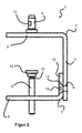
- FIGS. 1 and 2 show a clamp holder 1, as used for example to attach an office lamp to a desk (see FIG. 5 ) be used can, according to an embodiment of the invention, wherein the clamping bracket 1 in the FIGS. 1 and 2 is mounted in a first mounting variant so that it can be attached to tables with a particularly large thickness of the table top.
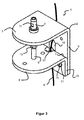
- FIGS. 1 and 2 show the in the FIGS. 1 and 2 illustrated clamping bracket 1, wherein the clamping bracket 1 in the Figures 3 and 4 mounted in a second mounting variant so that it can be attached to tables with a thin table top.
- the clamping bracket 1 has, as in the FIGS. 1 to 4 shown, an upper angle part 2 and a lower angle part 7 on.
- the upper angle part 2 comprises a clamping leg 3 and a back leg 5.
- the lower angle part 7 also has a clamping leg 8 and a back leg 10.
- the outer side of the clamping leg 3 of the upper angle part 2 should be considered as turned “up” and the outside of the clamping leg 8 of the lower angle part 7 are considered to be turned “down”.
- the two clamping legs 3, 8 are used to attach the clamping bracket 1 on a table top (not shown), whereas the two back legs 5, 10 of the attachment of the two angle parts 2, 7 serve each other.
- the back leg 5 of the upper angle part 2 in this embodiment two screw holes 6 with internal thread (see Figures 2 and 4 ) and the back leg 10 of the lower angle part 7 two round through holes 11, here sink holes 11 (see Figures 2 and 4 ) for each one fastening screw 15 (see FIGS. 1 to 4 ), wherein the diameter of the through holes 11 is adapted to the thread diameter of the screw and the reduction to the screw head.
- the back leg 5 of the upper angle part 2 has an annular recess 16 for the passage of a cable K in the inner region of the clamping bracket 1.
- the lower angle part 7 has a slot 17 in its back leg 10, which passes through the entire back leg 10 of the lower angle part 7 in the vertical direction and beyond the edge between the back leg 10 and the clamping leg 8 of the lower angle part 7 a piece far in the clamping leg 8 of the lower angle part 7 extends in, so that in the mounted state of the slot 17 together with the back leg 5 of the upper angle part 2 for the cable K a guide groove and a semicircular passage to the outside of the lower angle part 7 of the clamp 1 forms (see FIGS. 1 and 3 ).
- a coupling element 11 in the form of a coupling pin 11 is attached to the top of the clamping leg 1 of the upper angle part 2.
- a collar 12 is arranged below.
- This coupling pin 11 is cylindrical in shape, but has in its lateral surface on two opposite sides in each case notches 15, in which locking elements which are arranged in a coupling sleeve of the object to be coupled thereto - ie the desk lamp 100 - (not shown), can intervene.
- the coupling sleeve is freely rotatable about the longitudinal axis of the connecting bolt 10 on the coupling pin 11, so that correspondingly the desk lamp 100 can be pivoted into an arbitrary position.
- the locking elements in the interior of the coupling sleeve are formed so that they engage in most positions in the notches 15 on the coupling pin 11 and not rest in a certain position in the notches 15. In this position, the user can then relatively easily remove the lamp 100 with the coupling sleeve from above from the coupling pin 11.
- the coupling pin 11 has a chamfer 19 on its upper end face or on the circumferential peripheral edge of the end face.
- the clamping element 9 is in this Embodiment designed as a clamping pin 9 (or clamping bolt) with a pressure plate 13.
- the pressure plate 13 is mounted with respect to the clamping pin 9 with a ball joint 14.
- the clamping pin 9 is mounted in this embodiment on the clamping leg 8 of the lower angle part 7 by means of a screw thread (not shown) adjustable in the vertical direction.
- the clamping leg 8 of the lower angle part 7 has a vertically extending internal thread (not shown) and the clamping pin 9 on its outer side a longitudinally extending external thread (not shown).
- the entire clamping pin 9 may be formed as a threaded rod.
- the lower angle part 7 can be in two different orientations, namely anti-parallel to the upper angle part 2, as in the FIGS. 1 and 2 is shown, and parallel to the upper angle part 2, as in the Figures 3 and 4 is shown mounted on the upper angle part 2.
- the range of application of the clamp holder 1 extends to table tops with very different table top thicknesses.
- the clamp holder 1 is particularly suitable for attachment to tables with large table top thicknesses.
- FIG. 5 shows an insert of the clamp 1 for mounting a desk lamp 100 on a (relatively thin) table top T.
- the guided through the clamp 1 cable K can then z. B. connected to the lamp 100.
Applications Claiming Priority (1)
| Application Number | Priority Date | Filing Date | Title |
|---|---|---|---|
| DE102014115091.0A DE102014115091A1 (de) | 2014-10-16 | 2014-10-16 | Klemmhalterung |
Publications (2)
| Publication Number | Publication Date |
|---|---|
| EP3009738A1 true EP3009738A1 (fr) | 2016-04-20 |
| EP3009738B1 EP3009738B1 (fr) | 2018-12-05 |
Family
ID=54256642
Family Applications (1)
| Application Number | Title | Priority Date | Filing Date |
|---|---|---|---|
| EP15188196.8A Active EP3009738B1 (fr) | 2014-10-16 | 2015-10-02 | Support de serrage |
Country Status (2)
| Country | Link |
|---|---|
| EP (1) | EP3009738B1 (fr) |
| DE (1) | DE102014115091A1 (fr) |
Cited By (3)
| Publication number | Priority date | Publication date | Assignee | Title |
|---|---|---|---|---|
| US10610009B1 (en) | 2019-06-24 | 2020-04-07 | Berlin Dirgantara Ciputra | Removable table leg |
| USD920726S1 (en) | 2019-06-24 | 2021-06-01 | Berlin Dirgantara Ciputra | Removable table leg |
| CN113242781A (zh) * | 2018-12-21 | 2021-08-10 | 富兰卡爱米卡股份有限公司 | 用于将机器人机械手支承在工作台面上的机器人保持器 |
Families Citing this family (1)
| Publication number | Priority date | Publication date | Assignee | Title |
|---|---|---|---|---|
| DE102018003212A1 (de) * | 2018-04-20 | 2019-10-24 | Trilux Gmbh & Co. Kg | Leuchtensockelanordnung zur Befestigung einer Leuchte an einer Platte, insbesondere an einem Tisch |
Citations (11)
| Publication number | Priority date | Publication date | Assignee | Title |
|---|---|---|---|---|
| GB650282A (en) * | 1946-12-05 | 1951-02-21 | William Herscovitch | An improved clamp |
| DE730276C (de) | 1941-03-18 | 1953-03-02 | Franz Hanel | Als Tischklemme verwendbare buegelfoermige Schraubzwinge |
| US3328023A (en) * | 1964-12-29 | 1967-06-27 | Danko John | Clamp |
| DE9113012U1 (fr) | 1991-10-17 | 1991-12-19 | Haseke Gmbh & Co Kg, 4952 Porta Westfalica, De | |
| DE9204550U1 (fr) | 1992-04-04 | 1992-06-11 | Haseke Gmbh & Co Kg, 4952 Porta Westfalica, De | |
| DE9402835U1 (de) | 1994-02-22 | 1994-04-21 | Mertens Walter | Klemmhalter |
| WO2000025640A1 (fr) * | 1998-11-02 | 2000-05-11 | Innovative Office Products, Inc. | Monture configurable |
| US20050284995A1 (en) * | 2004-06-23 | 2005-12-29 | Physical Systems, Inc. | Adjustable mounting bracket |
| US20100207003A1 (en) * | 2008-10-05 | 2010-08-19 | Bruno Adrian A | Support Clamp |
| WO2014058126A1 (fr) * | 2012-10-08 | 2014-04-17 | Kim Jungrul | Dispositif de correction de posture |
| CN203731041U (zh) * | 2014-01-16 | 2014-07-23 | 余亦枢 | 一种平板电脑支架 |
Family Cites Families (1)
| Publication number | Priority date | Publication date | Assignee | Title |
|---|---|---|---|---|
| GB2298569A (en) * | 1995-03-01 | 1996-09-11 | Chuang Pi Yu | Support assembly for work station equipment |
-
2014
- 2014-10-16 DE DE102014115091.0A patent/DE102014115091A1/de active Pending
-
2015
- 2015-10-02 EP EP15188196.8A patent/EP3009738B1/fr active Active
Patent Citations (11)
| Publication number | Priority date | Publication date | Assignee | Title |
|---|---|---|---|---|
| DE730276C (de) | 1941-03-18 | 1953-03-02 | Franz Hanel | Als Tischklemme verwendbare buegelfoermige Schraubzwinge |
| GB650282A (en) * | 1946-12-05 | 1951-02-21 | William Herscovitch | An improved clamp |
| US3328023A (en) * | 1964-12-29 | 1967-06-27 | Danko John | Clamp |
| DE9113012U1 (fr) | 1991-10-17 | 1991-12-19 | Haseke Gmbh & Co Kg, 4952 Porta Westfalica, De | |
| DE9204550U1 (fr) | 1992-04-04 | 1992-06-11 | Haseke Gmbh & Co Kg, 4952 Porta Westfalica, De | |
| DE9402835U1 (de) | 1994-02-22 | 1994-04-21 | Mertens Walter | Klemmhalter |
| WO2000025640A1 (fr) * | 1998-11-02 | 2000-05-11 | Innovative Office Products, Inc. | Monture configurable |
| US20050284995A1 (en) * | 2004-06-23 | 2005-12-29 | Physical Systems, Inc. | Adjustable mounting bracket |
| US20100207003A1 (en) * | 2008-10-05 | 2010-08-19 | Bruno Adrian A | Support Clamp |
| WO2014058126A1 (fr) * | 2012-10-08 | 2014-04-17 | Kim Jungrul | Dispositif de correction de posture |
| CN203731041U (zh) * | 2014-01-16 | 2014-07-23 | 余亦枢 | 一种平板电脑支架 |
Cited By (4)
| Publication number | Priority date | Publication date | Assignee | Title |
|---|---|---|---|---|
| CN113242781A (zh) * | 2018-12-21 | 2021-08-10 | 富兰卡爱米卡股份有限公司 | 用于将机器人机械手支承在工作台面上的机器人保持器 |
| US20220024027A1 (en) * | 2018-12-21 | 2022-01-27 | Franka Emika Gmbh | Robot fixture for mounting a robot manipulator on a tabletop |
| US10610009B1 (en) | 2019-06-24 | 2020-04-07 | Berlin Dirgantara Ciputra | Removable table leg |
| USD920726S1 (en) | 2019-06-24 | 2021-06-01 | Berlin Dirgantara Ciputra | Removable table leg |
Also Published As
| Publication number | Publication date |
|---|---|
| EP3009738B1 (fr) | 2018-12-05 |
| DE102014115091A1 (de) | 2016-04-21 |
Similar Documents
| Publication | Publication Date | Title |
|---|---|---|
| EP3114359B1 (fr) | Dispositif servant à assembler un élément de structure à un élément de maintien selon un espacement l'un par rapport à l'autre | |
| EP3009738B1 (fr) | Support de serrage | |
| WO2008089870A2 (fr) | Rail de guidage pour un système de guidage linéaire | |
| DE102010033451A1 (de) | Stromschienenanordnung | |
| EP2579402B1 (fr) | Dispositif de fixation destiné à fixer un appareil d'installation sur un rail de support | |
| EP0237768A2 (fr) | Dispositif d'assemblage spatial d'éléments | |
| DE202013005582U1 (de) | System umfassend ein Trägerbauteil | |
| EP1222406B1 (fr) | Element de retenue pour vis a tete | |
| EP0407564A1 (fr) | Arret de vis | |
| DE202011005397U1 (de) | Klemmkörper zur Verbindung von mindestens zwei Gegenständen, insbesondere elektrischen Leitern | |
| EP1621781A1 (fr) | Dispositif de fixation pour profilé | |
| EP2138069B1 (fr) | Kit de production d'une table multifonctionnelle d'écriture ou de travail | |
| DE102007049513B4 (de) | Zirkel | |
| DE102012002525B4 (de) | Kondensator mit einem Gehäuse und einem am Gehäuseboden angeordneten Befestigungsbolzen | |
| DE4301975C1 (de) | Blechmutter zur Befestigung eines Losteils an einem Tragteil | |
| DE102015107245A1 (de) | Einstellvorrichtung für eine beleuchtungskomponente eines mikroskops, eine mikroskop-beleuchtungsvorrichtung und ein mikroskop | |
| EP3623698B1 (fr) | Luminaire | |
| DE102018105970B4 (de) | Variable Deckenbefestigung | |
| DE102010047502B4 (de) | Tischbein mit einem Verbindungssystem zum Verbinden von Tischplatten | |
| DE102006029826B4 (de) | Leuchtenbefestigungsvorrichtung | |
| EP3012504B1 (fr) | Adaptateur | |
| DE202009014827U1 (de) | Befestigungsvorrichtung für ein in einer Aussparung einer flachen Platte angeordnetes Gehäuse | |
| EP1873403A2 (fr) | Dispositif de fixation doté d'une base rotative | |
| DE202013102978U1 (de) | Möbelbeschlag | |
| DE202009004070U1 (de) | Deckenhalter zur hängenden Befestigung eines Gerätes, insbesondere eines Projektors |
Legal Events
| Date | Code | Title | Description |
|---|---|---|---|
| PUAI | Public reference made under article 153(3) epc to a published international application that has entered the european phase |
Free format text: ORIGINAL CODE: 0009012 |
|
| AK | Designated contracting states |
Kind code of ref document: A1 Designated state(s): AL AT BE BG CH CY CZ DE DK EE ES FI FR GB GR HR HU IE IS IT LI LT LU LV MC MK MT NL NO PL PT RO RS SE SI SK SM TR |
|
| AX | Request for extension of the european patent |
Extension state: BA ME |
|
| 17P | Request for examination filed |
Effective date: 20160930 |
|
| RBV | Designated contracting states (corrected) |
Designated state(s): AL AT BE BG CH CY CZ DE DK EE ES FI FR GB GR HR HU IE IS IT LI LT LU LV MC MK MT NL NO PL PT RO RS SE SI SK SM TR |
|
| STAA | Information on the status of an ep patent application or granted ep patent |
Free format text: STATUS: EXAMINATION IS IN PROGRESS |
|
| 17Q | First examination report despatched |
Effective date: 20170508 |
|
| GRAP | Despatch of communication of intention to grant a patent |
Free format text: ORIGINAL CODE: EPIDOSNIGR1 |
|
| STAA | Information on the status of an ep patent application or granted ep patent |
Free format text: STATUS: GRANT OF PATENT IS INTENDED |
|
| INTG | Intention to grant announced |
Effective date: 20171212 |
|
| GRAJ | Information related to disapproval of communication of intention to grant by the applicant or resumption of examination proceedings by the epo deleted |
Free format text: ORIGINAL CODE: EPIDOSDIGR1 |
|
| STAA | Information on the status of an ep patent application or granted ep patent |
Free format text: STATUS: EXAMINATION IS IN PROGRESS |
|
| GRAP | Despatch of communication of intention to grant a patent |
Free format text: ORIGINAL CODE: EPIDOSNIGR1 |
|
| STAA | Information on the status of an ep patent application or granted ep patent |
Free format text: STATUS: GRANT OF PATENT IS INTENDED |
|
| INTC | Intention to grant announced (deleted) | ||
| INTG | Intention to grant announced |
Effective date: 20180305 |
|
| GRAS | Grant fee paid |
Free format text: ORIGINAL CODE: EPIDOSNIGR3 |
|
| GRAJ | Information related to disapproval of communication of intention to grant by the applicant or resumption of examination proceedings by the epo deleted |
Free format text: ORIGINAL CODE: EPIDOSDIGR1 |
|
| GRAL | Information related to payment of fee for publishing/printing deleted |
Free format text: ORIGINAL CODE: EPIDOSDIGR3 |
|
| STAA | Information on the status of an ep patent application or granted ep patent |
Free format text: STATUS: EXAMINATION IS IN PROGRESS |
|
| GRAP | Despatch of communication of intention to grant a patent |
Free format text: ORIGINAL CODE: EPIDOSNIGR1 |
|
| STAA | Information on the status of an ep patent application or granted ep patent |
Free format text: STATUS: GRANT OF PATENT IS INTENDED |
|
| INTC | Intention to grant announced (deleted) | ||
| INTG | Intention to grant announced |
Effective date: 20180808 |
|
| GRAA | (expected) grant |
Free format text: ORIGINAL CODE: 0009210 |
|
| GRAA | (expected) grant |
Free format text: ORIGINAL CODE: 0009210 |
|
| STAA | Information on the status of an ep patent application or granted ep patent |
Free format text: STATUS: THE PATENT HAS BEEN GRANTED |
|
| AK | Designated contracting states |
Kind code of ref document: B1 Designated state(s): AL AT BE BG CH CY CZ DE DK EE ES FI FR GB GR HR HU IE IS IT LI LT LU LV MC MK MT NL NO PL PT RO RS SE SI SK SM TR |
|
| REG | Reference to a national code |
Ref country code: GB Ref legal event code: FG4D Free format text: NOT ENGLISH |
|
| REG | Reference to a national code |
Ref country code: CH Ref legal event code: EP |
|
| REG | Reference to a national code |
Ref country code: AT Ref legal event code: REF Ref document number: 1073519 Country of ref document: AT Kind code of ref document: T Effective date: 20181215 |
|
| REG | Reference to a national code |
Ref country code: IE Ref legal event code: FG4D Free format text: LANGUAGE OF EP DOCUMENT: GERMAN |
|
| REG | Reference to a national code |
Ref country code: DE Ref legal event code: R096 Ref document number: 502015007083 Country of ref document: DE |
|
| REG | Reference to a national code |
Ref country code: SE Ref legal event code: TRGR |
|
| REG | Reference to a national code |
Ref country code: NL Ref legal event code: MP Effective date: 20181205 |
|
| REG | Reference to a national code |
Ref country code: LT Ref legal event code: MG4D |
|
| PG25 | Lapsed in a contracting state [announced via postgrant information from national office to epo] |
Ref country code: ES Free format text: LAPSE BECAUSE OF FAILURE TO SUBMIT A TRANSLATION OF THE DESCRIPTION OR TO PAY THE FEE WITHIN THE PRESCRIBED TIME-LIMIT Effective date: 20181205 Ref country code: NO Free format text: LAPSE BECAUSE OF FAILURE TO SUBMIT A TRANSLATION OF THE DESCRIPTION OR TO PAY THE FEE WITHIN THE PRESCRIBED TIME-LIMIT Effective date: 20190305 Ref country code: LT Free format text: LAPSE BECAUSE OF FAILURE TO SUBMIT A TRANSLATION OF THE DESCRIPTION OR TO PAY THE FEE WITHIN THE PRESCRIBED TIME-LIMIT Effective date: 20181205 Ref country code: BG Free format text: LAPSE BECAUSE OF FAILURE TO SUBMIT A TRANSLATION OF THE DESCRIPTION OR TO PAY THE FEE WITHIN THE PRESCRIBED TIME-LIMIT Effective date: 20190305 Ref country code: HR Free format text: LAPSE BECAUSE OF FAILURE TO SUBMIT A TRANSLATION OF THE DESCRIPTION OR TO PAY THE FEE WITHIN THE PRESCRIBED TIME-LIMIT Effective date: 20181205 Ref country code: FI Free format text: LAPSE BECAUSE OF FAILURE TO SUBMIT A TRANSLATION OF THE DESCRIPTION OR TO PAY THE FEE WITHIN THE PRESCRIBED TIME-LIMIT Effective date: 20181205 Ref country code: LV Free format text: LAPSE BECAUSE OF FAILURE TO SUBMIT A TRANSLATION OF THE DESCRIPTION OR TO PAY THE FEE WITHIN THE PRESCRIBED TIME-LIMIT Effective date: 20181205 |
|
| PG25 | Lapsed in a contracting state [announced via postgrant information from national office to epo] |
Ref country code: RS Free format text: LAPSE BECAUSE OF FAILURE TO SUBMIT A TRANSLATION OF THE DESCRIPTION OR TO PAY THE FEE WITHIN THE PRESCRIBED TIME-LIMIT Effective date: 20181205 Ref country code: AL Free format text: LAPSE BECAUSE OF FAILURE TO SUBMIT A TRANSLATION OF THE DESCRIPTION OR TO PAY THE FEE WITHIN THE PRESCRIBED TIME-LIMIT Effective date: 20181205 Ref country code: GR Free format text: LAPSE BECAUSE OF FAILURE TO SUBMIT A TRANSLATION OF THE DESCRIPTION OR TO PAY THE FEE WITHIN THE PRESCRIBED TIME-LIMIT Effective date: 20190306 |
|
| PG25 | Lapsed in a contracting state [announced via postgrant information from national office to epo] |
Ref country code: NL Free format text: LAPSE BECAUSE OF FAILURE TO SUBMIT A TRANSLATION OF THE DESCRIPTION OR TO PAY THE FEE WITHIN THE PRESCRIBED TIME-LIMIT Effective date: 20181205 |
|
| PG25 | Lapsed in a contracting state [announced via postgrant information from national office to epo] |
Ref country code: IT Free format text: LAPSE BECAUSE OF FAILURE TO SUBMIT A TRANSLATION OF THE DESCRIPTION OR TO PAY THE FEE WITHIN THE PRESCRIBED TIME-LIMIT Effective date: 20181205 Ref country code: PL Free format text: LAPSE BECAUSE OF FAILURE TO SUBMIT A TRANSLATION OF THE DESCRIPTION OR TO PAY THE FEE WITHIN THE PRESCRIBED TIME-LIMIT Effective date: 20181205 Ref country code: PT Free format text: LAPSE BECAUSE OF FAILURE TO SUBMIT A TRANSLATION OF THE DESCRIPTION OR TO PAY THE FEE WITHIN THE PRESCRIBED TIME-LIMIT Effective date: 20190405 Ref country code: CZ Free format text: LAPSE BECAUSE OF FAILURE TO SUBMIT A TRANSLATION OF THE DESCRIPTION OR TO PAY THE FEE WITHIN THE PRESCRIBED TIME-LIMIT Effective date: 20181205 |
|
| PG25 | Lapsed in a contracting state [announced via postgrant information from national office to epo] |
Ref country code: EE Free format text: LAPSE BECAUSE OF FAILURE TO SUBMIT A TRANSLATION OF THE DESCRIPTION OR TO PAY THE FEE WITHIN THE PRESCRIBED TIME-LIMIT Effective date: 20181205 Ref country code: SM Free format text: LAPSE BECAUSE OF FAILURE TO SUBMIT A TRANSLATION OF THE DESCRIPTION OR TO PAY THE FEE WITHIN THE PRESCRIBED TIME-LIMIT Effective date: 20181205 Ref country code: RO Free format text: LAPSE BECAUSE OF FAILURE TO SUBMIT A TRANSLATION OF THE DESCRIPTION OR TO PAY THE FEE WITHIN THE PRESCRIBED TIME-LIMIT Effective date: 20181205 Ref country code: IS Free format text: LAPSE BECAUSE OF FAILURE TO SUBMIT A TRANSLATION OF THE DESCRIPTION OR TO PAY THE FEE WITHIN THE PRESCRIBED TIME-LIMIT Effective date: 20190405 Ref country code: SK Free format text: LAPSE BECAUSE OF FAILURE TO SUBMIT A TRANSLATION OF THE DESCRIPTION OR TO PAY THE FEE WITHIN THE PRESCRIBED TIME-LIMIT Effective date: 20181205 |
|
| REG | Reference to a national code |
Ref country code: DE Ref legal event code: R097 Ref document number: 502015007083 Country of ref document: DE |
|
| PLBE | No opposition filed within time limit |
Free format text: ORIGINAL CODE: 0009261 |
|
| STAA | Information on the status of an ep patent application or granted ep patent |
Free format text: STATUS: NO OPPOSITION FILED WITHIN TIME LIMIT |
|
| PG25 | Lapsed in a contracting state [announced via postgrant information from national office to epo] |
Ref country code: DK Free format text: LAPSE BECAUSE OF FAILURE TO SUBMIT A TRANSLATION OF THE DESCRIPTION OR TO PAY THE FEE WITHIN THE PRESCRIBED TIME-LIMIT Effective date: 20181205 Ref country code: SI Free format text: LAPSE BECAUSE OF FAILURE TO SUBMIT A TRANSLATION OF THE DESCRIPTION OR TO PAY THE FEE WITHIN THE PRESCRIBED TIME-LIMIT Effective date: 20181205 |
|
| 26N | No opposition filed |
Effective date: 20190906 |
|
| PG25 | Lapsed in a contracting state [announced via postgrant information from national office to epo] |
Ref country code: TR Free format text: LAPSE BECAUSE OF FAILURE TO SUBMIT A TRANSLATION OF THE DESCRIPTION OR TO PAY THE FEE WITHIN THE PRESCRIBED TIME-LIMIT Effective date: 20181205 |
|
| PG25 | Lapsed in a contracting state [announced via postgrant information from national office to epo] |
Ref country code: MC Free format text: LAPSE BECAUSE OF FAILURE TO SUBMIT A TRANSLATION OF THE DESCRIPTION OR TO PAY THE FEE WITHIN THE PRESCRIBED TIME-LIMIT Effective date: 20181205 |
|
| REG | Reference to a national code |
Ref country code: CH Ref legal event code: PL |
|
| PG25 | Lapsed in a contracting state [announced via postgrant information from national office to epo] |
Ref country code: LU Free format text: LAPSE BECAUSE OF NON-PAYMENT OF DUE FEES Effective date: 20191002 Ref country code: LI Free format text: LAPSE BECAUSE OF NON-PAYMENT OF DUE FEES Effective date: 20191031 Ref country code: CH Free format text: LAPSE BECAUSE OF NON-PAYMENT OF DUE FEES Effective date: 20191031 |
|
| REG | Reference to a national code |
Ref country code: BE Ref legal event code: MM Effective date: 20191031 |
|
| PG25 | Lapsed in a contracting state [announced via postgrant information from national office to epo] |
Ref country code: BE Free format text: LAPSE BECAUSE OF NON-PAYMENT OF DUE FEES Effective date: 20191031 |
|
| GBPC | Gb: european patent ceased through non-payment of renewal fee |
Effective date: 20191002 |
|
| PG25 | Lapsed in a contracting state [announced via postgrant information from national office to epo] |
Ref country code: IE Free format text: LAPSE BECAUSE OF NON-PAYMENT OF DUE FEES Effective date: 20191002 Ref country code: GB Free format text: LAPSE BECAUSE OF NON-PAYMENT OF DUE FEES Effective date: 20191002 Ref country code: FR Free format text: LAPSE BECAUSE OF NON-PAYMENT OF DUE FEES Effective date: 20191031 |
|
| PG25 | Lapsed in a contracting state [announced via postgrant information from national office to epo] |
Ref country code: CY Free format text: LAPSE BECAUSE OF FAILURE TO SUBMIT A TRANSLATION OF THE DESCRIPTION OR TO PAY THE FEE WITHIN THE PRESCRIBED TIME-LIMIT Effective date: 20181205 |
|
| PG25 | Lapsed in a contracting state [announced via postgrant information from national office to epo] |
Ref country code: MT Free format text: LAPSE BECAUSE OF FAILURE TO SUBMIT A TRANSLATION OF THE DESCRIPTION OR TO PAY THE FEE WITHIN THE PRESCRIBED TIME-LIMIT Effective date: 20181205 Ref country code: HU Free format text: LAPSE BECAUSE OF FAILURE TO SUBMIT A TRANSLATION OF THE DESCRIPTION OR TO PAY THE FEE WITHIN THE PRESCRIBED TIME-LIMIT; INVALID AB INITIO Effective date: 20151002 |
|
| REG | Reference to a national code |
Ref country code: AT Ref legal event code: MM01 Ref document number: 1073519 Country of ref document: AT Kind code of ref document: T Effective date: 20201002 |
|
| PG25 | Lapsed in a contracting state [announced via postgrant information from national office to epo] |
Ref country code: AT Free format text: LAPSE BECAUSE OF NON-PAYMENT OF DUE FEES Effective date: 20201002 |
|
| PG25 | Lapsed in a contracting state [announced via postgrant information from national office to epo] |
Ref country code: MK Free format text: LAPSE BECAUSE OF FAILURE TO SUBMIT A TRANSLATION OF THE DESCRIPTION OR TO PAY THE FEE WITHIN THE PRESCRIBED TIME-LIMIT Effective date: 20181205 |
|
| PGFP | Annual fee paid to national office [announced via postgrant information from national office to epo] |
Ref country code: SE Payment date: 20231019 Year of fee payment: 9 Ref country code: DE Payment date: 20231031 Year of fee payment: 9 |