EP3004864B1 - Procede d'inspection par transmission d'ultrasons ameliore - Google Patents
Procede d'inspection par transmission d'ultrasons ameliore Download PDFInfo
- Publication number
- EP3004864B1 EP3004864B1 EP14731705.1A EP14731705A EP3004864B1 EP 3004864 B1 EP3004864 B1 EP 3004864B1 EP 14731705 A EP14731705 A EP 14731705A EP 3004864 B1 EP3004864 B1 EP 3004864B1
- Authority
- EP
- European Patent Office
- Prior art keywords
- amplitude
- gain
- scanning
- point
- ultrasound beam
- Prior art date
- Legal status (The legal status is an assumption and is not a legal conclusion. Google has not performed a legal analysis and makes no representation as to the accuracy of the status listed.)
- Active
Links
Images


Classifications
-
- G—PHYSICS
- G01—MEASURING; TESTING
- G01H—MEASUREMENT OF MECHANICAL VIBRATIONS OR ULTRASONIC, SONIC OR INFRASONIC WAVES
- G01H1/00—Measuring characteristics of vibrations in solids by using direct conduction to the detector
- G01H1/003—Measuring characteristics of vibrations in solids by using direct conduction to the detector of rotating machines
-
- G—PHYSICS
- G01—MEASURING; TESTING
- G01N—INVESTIGATING OR ANALYSING MATERIALS BY DETERMINING THEIR CHEMICAL OR PHYSICAL PROPERTIES
- G01N29/00—Investigating or analysing materials by the use of ultrasonic, sonic or infrasonic waves; Visualisation of the interior of objects by transmitting ultrasonic or sonic waves through the object
- G01N29/04—Analysing solids
- G01N29/11—Analysing solids by measuring attenuation of acoustic waves
-
- G—PHYSICS
- G01—MEASURING; TESTING
- G01N—INVESTIGATING OR ANALYSING MATERIALS BY DETERMINING THEIR CHEMICAL OR PHYSICAL PROPERTIES
- G01N29/00—Investigating or analysing materials by the use of ultrasonic, sonic or infrasonic waves; Visualisation of the interior of objects by transmitting ultrasonic or sonic waves through the object
- G01N29/44—Processing the detected response signal, e.g. electronic circuits specially adapted therefor
- G01N29/4463—Signal correction, e.g. distance amplitude correction [DAC], distance gain size [DGS], noise filtering
-
- G—PHYSICS
- G01—MEASURING; TESTING
- G01N—INVESTIGATING OR ANALYSING MATERIALS BY DETERMINING THEIR CHEMICAL OR PHYSICAL PROPERTIES
- G01N2291/00—Indexing codes associated with group G01N29/00
- G01N2291/02—Indexing codes associated with the analysed material
- G01N2291/023—Solids
- G01N2291/0231—Composite or layered materials
-
- G—PHYSICS
- G01—MEASURING; TESTING
- G01N—INVESTIGATING OR ANALYSING MATERIALS BY DETERMINING THEIR CHEMICAL OR PHYSICAL PROPERTIES
- G01N2291/00—Indexing codes associated with group G01N29/00
- G01N2291/02—Indexing codes associated with the analysed material
- G01N2291/028—Material parameters
- G01N2291/0289—Internal structure, e.g. defects, grain size, texture
-
- G—PHYSICS
- G01—MEASURING; TESTING
- G01N—INVESTIGATING OR ANALYSING MATERIALS BY DETERMINING THEIR CHEMICAL OR PHYSICAL PROPERTIES
- G01N2291/00—Indexing codes associated with group G01N29/00
- G01N2291/04—Wave modes and trajectories
- G01N2291/044—Internal reflections (echoes), e.g. on walls or defects
-
- G—PHYSICS
- G01—MEASURING; TESTING
- G01N—INVESTIGATING OR ANALYSING MATERIALS BY DETERMINING THEIR CHEMICAL OR PHYSICAL PROPERTIES
- G01N2291/00—Indexing codes associated with group G01N29/00
- G01N2291/04—Wave modes and trajectories
- G01N2291/048—Transmission, i.e. analysed material between transmitter and receiver
Definitions
- the invention relates to the field of non-destructive inspection methods of objects by ultrasound transmission to detect internal anomalies, such as porosities, delaminations, cracks, etc. present in the volume of the inspected object or gluing defects in the event that the inspected object is formed by the association of several parts.
- the invention applies in particular to the inspection of parts with a complex geometry, such as blades and turbine engine blade housings.
- a known technique is the inspection by reflection, during which a scanning of an object to be inspected is carried out with an ultrasound beam at a determined gain, and the amplitude of the beam reflected by the object is measured in order to detect d 'possible alterations in the internal structure of the object.
- the ultrasound reflection test method is not suitable for objects made of a material which strongly absorbs ultrasound, such as for example composite materials.
- a material which strongly absorbs ultrasound such as for example composite materials.
- a more suitable inspection method is ultrasonic transmission inspection using the “C-Scan” type representation. This implies access to two opposite sides of the part to be inspected. The receiver is then placed in front of the transmitter and it collects the energy which has been transmitted through the room. Reflectors such as interfaces or anomalies will be detected by a decrease in this energy, but it is not possible to locate them in the thickness of the part.
- a map is then produced representing a projection of the inspected object along the direction of the ultrasound beam, each point of which is colored according to the amplitude.
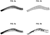
- Such a mapping carried out at a leading edge of a turbomachine blade, is represented in figure 4a .
- the darker areas correspond to areas where the amplitude of the transmitted ultrasound beam is low, that is to say where the attenuation is great.
- the reduction in the amplitude of the ultrasound beam depends both on the thickness of the material passed through and on any defects encountered; for example, if a cavity is in the inspected object, on the path of the ultrasound beam, the ultrasound beam is not transmitted through this cavity, and the amplitude transmitted at this cavity is therefore very reduced compared to the initial emission amplitude.
- the inspected object has a complex geometry, which is the case for example of turbine engine blades, or of blade housings, it is therefore impossible, with the method of inspection by transmission of ultrasound, to differentiate between an area with a defect and an area where the thickness of material to pass through is important, or even a misalignment of the probes due to the geometry of the part.
- the left part of the figure corresponds to the root of the blade and the right part corresponds to the head of the blade, this blade being represented on the figure 1 .
- the left end of the cartography on the figure 5a corresponding to the root of the vane has a dark coloration, indicating a strong absorption of ultrasound at this level of the vane.
- this strong absorption can be linked to a defect in this root or result from the thickness of the blade at this level, but it is not possible to determine it with this mapping.
- a method could include multiple scans of the same part with ultrasound beams having a different gain at each scan and each step.
- this process would waste too much time.
- the object of the invention is to provide a method for inspecting an object making it possible to immediately identify defects present in the structure of the object.
- Another object of the invention is to be able to be used whatever the geometry of the inspected object.
- the invention also relates to a use of the inspection method for inspecting a blade, in particular a blade formed of a composite material and further comprising a metal reinforcement bonded to its leading edge, said method making it possible to detect any gluing anomalies or for the inspection of a blading housing.
- the proposed inspection method makes it possible to do away with the geometry of an object, so that the reductions in energy represented on the map resulting from the inspection are linked only to structural defects of the object.
- the fact of using a reference part, which is known to be free from defects makes it possible to adapt the gain of the reception signal of the ultrasound beam to the thickness of the object inspected at the level from the point of exposure.
- the amplitude of the ultrasound beam is modified so that the object appears to have a constant thickness. It follows that the transmitted amplitude variations can only come from defects of the inspected object, the variations related to the thickness of the object being eliminated.
- This method therefore makes it possible to inspect parts with complex geometry more quickly and with improved reliability.
- FIG. 2 there is schematically shown a system 100 for inspecting an object O by transmission of ultrasound used for implementing the method described below.
- This system comprises a probe 110 for emitting an ultrasound beam, which is moved along a predetermined path by means 120 for controlling the scanning of said probe.
- the receiver 130 On the other side of the probed object O is positioned the receiver 130.
- the probe 110 and the receiver 130 are piezoelectric transducers, able to convert an electrical signal into a mechanical wave and vice versa. Therefore, the roles of the probe and the receptor can be reversed.
- the probe is electrically excited by a signal supplied by a generator 141 of a processing unit 140 to emit ultrasonic waves, and the receiver 130 converts the ultrasonic waves having propagated through the object being probed. into an electrical signal.
- the amplitude of the ultrasound beam transmitted through the object is measured as follows.
- the electrical signal converted by the receiver is transmitted to the processing unit 140, which includes an amplifier 142 to amplify the electrical signal with a desired gain, said gain corresponding to an amplitude gain of the ultrasound beam transmitted through the object O.
- the processing unit further comprises a control unit 143, which can advantageously be a processor, which then measures the amplitude of the electrical signal thus amplified, said amplitude corresponding to the amplitude of the ultrasound beam.
- the control unit 143 is further adapted to associate with each point of the scan of the object probed the amplitude of the ultrasound beam transmitted through the object at said point of the scan.
- the word "mapping” is understood to mean this linking of the points with the respective amplitude, whether or not it is followed by a display of the two-dimensional object representing each point of the scan in one. particular color depending on its transmitted amplitude.
- the inspection system 100 further comprises a display 150 making it possible to represent said map.
- the control unit 142 is also suitable for controlling the gain provided by the amplifier 142 to the ultrasound beam received by the receiver 130, as will be seen below.
- This method comprises the implementation of an object control by ultrasound transmission of the “C-Scan” type, comprising a first measurement step, during which an object to be inspected is scanned with a beam.
- ultrasound by amplifying the signal received from the ultrasound transmitted through the object a determined gain, and measuring the amplitude of the ultrasound beam transmitted through the object after amplification, and a second interpretation step , during which, from these amplitude measurements, a two-dimensional mapping of the object is established, this mapping being a projection of the inspected object along the direction of exposure of the ultrasound beam.
- the object is represented therein in colors or in shades of gray, each point of the map being associated, by its color, with the amplitude of the ultrasound beam transmitted through said object.
- This check is first implemented on a reference part during an initialization step 1000, to deduce therefrom, for this part, the gain corrections of the transmitted signal to be made to the gain of the amplifier 142, so that the amplitude of the ultrasound transmitted through said part is constant.
- the method comprises a step of inspection 2000 proper of each object O to be inspected, comprising the implementation of a “C-Scan” type control using the gain corrected from the corrections as ultrasound reception gain. determined during the initialization step.
- the reference part is a part with the same geometry, ie the same dimensions, as the object to be inspected.
- the object to be inspected is a turbine engine blade
- the reference part is a blade of the same design.
- the reference part must have been selected and checked by other means to verify that it does not contain any defect.
- the reference part is scanned by an ultrasound beam emitted by the probe with a predetermined amplitude A s .
- the receiver receives the ultrasound beam and transmits an electrical signal corresponding to the processing unit.
- the control unit 143 of the processing unit measures the transmitted amplitude A t of the ultrasound for a predetermined reference gain P ref of the amplifier 142 through said part at each point of the scan and in deduced during a sub-step 1200 a map associating with each point of the scan the amplitude transmitted at said point.
- the control unit determines during a sub-step 1300, at each point of the scan, the amplification gain of the received energy G c which should be selected so that the amplitude of the ultrasound transmitted through said part is constant for all the points of the scan, and deduces therefrom a list of corrections to be made to the reference gain G ref at each point of the scan in order to obtain the corrected gain G c .
- This determination of the gain corrections can be performed after the entire part scan has been completed. Alternatively, and preferably, the determination of the gain corrections can be carried out in real time, that is to say that the determination and application of a gain correction to be made to the reference gain G ref at level d A point of the scanning of the part is determined at the time of scanning of said point by the control unit 143.
- the constant amplitude A c transmitted with the corrected gain is preferably greater than 60% of the amplitude A s of the ultrasounds emitted by the probe, to then allow good resolution of the data acquired.
- the amplitude with the corrected gain is between 70 and 90% of the amplitude A s of the ultrasound emitted, and preferably of the order of 80%. This represents a good compromise between the amplitude and the resolution obtained.
- figure 4a a map obtained for the reference part by applying the reference gain G ref of the ultrasound, and by figure 4b the corrected gain G c . It is clearly observed on the map that the variations in the transmitted amplitude due to the variations in thickness of the part are suppressed, and that the transmitted amplitude A c after correction is constant.
- this object must have the same geometry and the same structure as the reference part, for the list of corrections established for the sweep points to be valid.
- the object is scanned by an ultrasound beam, the gain of which at each point of the scan is the corrected gain G c , that is to say the reference gain G ref to which the corrections determined above have been added.
- the receiver picks up the ultrasonic beam and the control unit measures the amplitude of the amplified signal with the corrected gain.
- the control unit 143 performs a mapping of the probed object, by associating with each point of the scan the amplitude of the ultrasound transmitted through the object and received by the receiver.
- this mapping is represented on the display during a step 2300, each point of the scan being represented with a color or a shade of gray representative of the attenuation rate of the transmitted amplitude, or of the transmitted amplitude. herself.
- This turbomachine blade 10 is made of a composite material and has a metal reinforcement 11 on its leading edge, as shown in figure 1 .
- the inspection method is used in particular to identify bonding defects of the reinforcement on the leading edge.
- bonding defects were simulated in the tested blade of the figures 5a and 5b by positioning inserts in absorbent material between the leading edge of the blade and the metal reinforcement.
- the analysis of the map obtained, carried out during a step 2400, either by an operator or automatically, for example by setting up a transmitted amplitude threshold and comparing the values acquired at the different points of the scanning with respect to said threshold, makes it possible to detect or visualize very easily in the figures anomalies from the amplitude transmitted through the part which may correspond to defects in the internal structure of the objects examined. This method therefore makes it possible to identify faults more quickly than the methods proposed so far.
- the inspection step 2000 can therefore be repeated for each new object to be inspected, without having to repeat the step 1000, as shown in the figure. figure 3 with steps 2000 'and 2000 ".
- the reference part and the inspected object are axisymmetric, that is to say symmetrical of revolution about an axis, their surface thus resulting from the revolution of a line around the axis of symmetry.
- This is the case, for example, of a turbomachine blading housing.
- step 1000 for initializing the method can be simplified by determining a list of gain corrections to be made. only for a radial profile of the part, these gain corrections being transposable to the entire circumference of the part.
- the direction of exposure of the ultrasound beam is radial with respect to the axis of symmetry, and the reference part is scanned along a line of said part at the intersection of the surface of the reference part with a radial plane.
- the reference part is scanned along a single line, but the scanning can also be repeated over several lines to check the gain corrections obtained.
- the whole of the axisymmetric object to be inspected is probed according to scanning lines of the ultrasound beam identical to the scanning line carried out to establish the corrections of gain, by applying the corresponding correction to each point of said line.
- the method is particularly suitable for the inspection of turbine engine blading housings made of composite material, to detect porosity and delamination type defects in the material, including at the level of the flange allowing the housing to be fixed to other elements. of the turbomachine, this flange having a bulk making it impossible to inspect it in the small radius (angle of 90 °) and causing misalignment of the probes leading to loss of the signal.
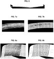
- FIG. 8a and 8b there is shown a map obtained for the casing, at the level of the flow of the latter, before and after application of the gain corrections.
- the square defects in the housing structure are also much more visible.
- the method of inspecting objects proposed is in no way limited to one type of object to be inspected in particular, but advantageously applies to turbine engine blades or to turbomachine blading housings, or to any other object. presenting a complex geometry with many variations in thickness.
- the invention is applicable to any object made of a material exhibiting a high rate of absorption of ultrasound such as a composite material, and in particular in a 3D woven or 3D interlock composite material, that is to say ie comprising a reinforcing structure taken from a matrix, for example made of polymer material.
- the method therefore makes it possible to easily check these objects, and even to immediately visualize the faults which they may contain.
Landscapes
- Physics & Mathematics (AREA)
- General Physics & Mathematics (AREA)
- Biochemistry (AREA)
- Life Sciences & Earth Sciences (AREA)
- Chemical & Material Sciences (AREA)
- Analytical Chemistry (AREA)
- Health & Medical Sciences (AREA)
- General Health & Medical Sciences (AREA)
- Immunology (AREA)
- Pathology (AREA)
- Engineering & Computer Science (AREA)
- Signal Processing (AREA)
- Acoustics & Sound (AREA)
- Investigating Or Analyzing Materials By The Use Of Ultrasonic Waves (AREA)
Applications Claiming Priority (2)
| Application Number | Priority Date | Filing Date | Title |
|---|---|---|---|
| FR1354956A FR3006447B1 (fr) | 2013-05-30 | 2013-05-30 | Procede d'inspection par transmission d'ultrasons ameliore |
| PCT/FR2014/051202 WO2014191661A1 (fr) | 2013-05-30 | 2014-05-22 | Procede d'inspection par transmission d'ultrasons ameliore |
Publications (2)
| Publication Number | Publication Date |
|---|---|
| EP3004864A1 EP3004864A1 (fr) | 2016-04-13 |
| EP3004864B1 true EP3004864B1 (fr) | 2021-01-13 |
Family
ID=49054754
Family Applications (1)
| Application Number | Title | Priority Date | Filing Date |
|---|---|---|---|
| EP14731705.1A Active EP3004864B1 (fr) | 2013-05-30 | 2014-05-22 | Procede d'inspection par transmission d'ultrasons ameliore |
Country Status (9)
Cited By (1)
| Publication number | Priority date | Publication date | Assignee | Title |
|---|---|---|---|---|
| FR3127813A1 (fr) * | 2021-10-05 | 2023-04-07 | Safran Aircraft Engines | Procede de mesure par ultrasons en transmission d’une piece mecanique d’une turbomachine d’aeronef |
Families Citing this family (18)
| Publication number | Priority date | Publication date | Assignee | Title |
|---|---|---|---|---|
| US10338036B2 (en) * | 2014-05-01 | 2019-07-02 | TecScan Systems Inc. | Method and apparatus for scanning a test object and correcting for gain |
| FR3068134B1 (fr) * | 2017-06-23 | 2021-01-08 | Vallourec Tubes France | Controle non destructif pour produit tubulaire a forme complexe |
| CN107677730A (zh) * | 2017-08-07 | 2018-02-09 | 中材科技(阜宁)风电叶片有限公司 | 风电叶片前缘粘接区的无损检测方法 |
| US10958843B2 (en) | 2018-05-04 | 2021-03-23 | Raytheon Technologies Corporation | Multi-camera system for simultaneous registration and zoomed imagery |
| US10943320B2 (en) | 2018-05-04 | 2021-03-09 | Raytheon Technologies Corporation | System and method for robotic inspection |
| US10685433B2 (en) | 2018-05-04 | 2020-06-16 | Raytheon Technologies Corporation | Nondestructive coating imperfection detection system and method therefor |
| US10473593B1 (en) | 2018-05-04 | 2019-11-12 | United Technologies Corporation | System and method for damage detection by cast shadows |
| US10928362B2 (en) | 2018-05-04 | 2021-02-23 | Raytheon Technologies Corporation | Nondestructive inspection using dual pulse-echo ultrasonics and method therefor |
| US11268881B2 (en) | 2018-05-04 | 2022-03-08 | Raytheon Technologies Corporation | System and method for fan blade rotor disk and gear inspection |
| US11079285B2 (en) | 2018-05-04 | 2021-08-03 | Raytheon Technologies Corporation | Automated analysis of thermally-sensitive coating and method therefor |
| US10902664B2 (en) | 2018-05-04 | 2021-01-26 | Raytheon Technologies Corporation | System and method for detecting damage using two-dimensional imagery and three-dimensional model |
| US10488371B1 (en) * | 2018-05-04 | 2019-11-26 | United Technologies Corporation | Nondestructive inspection using thermoacoustic imagery and method therefor |
| US10914191B2 (en) | 2018-05-04 | 2021-02-09 | Raytheon Technologies Corporation | System and method for in situ airfoil inspection |
| CN108645915A (zh) * | 2018-05-07 | 2018-10-12 | 广东工业大学 | 一种超声感声屏、超声检测系统及方法 |
| JP7112726B2 (ja) * | 2018-08-10 | 2022-08-04 | ヤマハファインテック株式会社 | 超音波検査装置、及び超音波検査方法 |
| CN110398503A (zh) * | 2019-02-27 | 2019-11-01 | 广西壮族自治区农业科学院 | 一种基于几何形态透射测量的植物病虫害检验方法 |
| US11717967B2 (en) | 2021-03-04 | 2023-08-08 | TecScan Systems Inc. | System and method for scanning an object using an array of ultrasonic transducers |
| FR3150295A1 (fr) * | 2023-06-21 | 2024-12-27 | Safran Aircraft Engines | Procédé de détection par ultrasons de défauts de type zone d’air dans une pièce |
Citations (1)
| Publication number | Priority date | Publication date | Assignee | Title |
|---|---|---|---|---|
| US20120101764A1 (en) * | 2010-10-20 | 2012-04-26 | Sonix, Inc. | Method and apparatus for adjusting the level of a response signal from an ultrasound transducer |
Family Cites Families (31)
| Publication number | Priority date | Publication date | Assignee | Title |
|---|---|---|---|---|
| US2378237A (en) * | 1942-09-02 | 1945-06-12 | Wingfoot Corp | Method and apparatus for ultrasonic testing |
| US4004454A (en) * | 1975-05-07 | 1977-01-25 | Trw Inc. | Ultrasonic inspection method of pulse reflection defect detection using a thru-transmission automatic distance-amplitude compensation |
| US4462082A (en) * | 1981-09-17 | 1984-07-24 | Rockwell International Corporation | Automatic calibration system for ultrasonic inspection |
| JPS599555A (ja) * | 1982-07-08 | 1984-01-18 | Toshiba Corp | 超音波探傷装置 |
| US4607341A (en) * | 1984-03-05 | 1986-08-19 | Canadian Patents And Development Limited | Device for determining properties of materials from a measurement of ultrasonic absorption |
| GB8423023D0 (en) * | 1984-09-12 | 1984-10-17 | Short Brothers Ltd | Ultrasonic scanning system |
| SU1350605A1 (ru) * | 1986-07-14 | 1987-11-07 | Всесоюзный научно-исследовательский и конструкторско-технологический институт трубной промышленности | Способ ультразвукового контрол качества соединений многослойных труб |
| JPS63263467A (ja) * | 1987-04-22 | 1988-10-31 | Mitsubishi Heavy Ind Ltd | 超音波探傷方法 |
| SU1649417A1 (ru) * | 1988-08-02 | 1991-05-15 | Предприятие П/Я А-7650 | Устройство дл ультразвукового контрол труб |
| JPH03205552A (ja) * | 1989-10-13 | 1991-09-09 | Fuji Electric Co Ltd | 飛行機翼の自動超音波探傷装置 |
| US5241473A (en) * | 1990-10-12 | 1993-08-31 | Ken Ishihara | Ultrasonic diagnostic apparatus for displaying motion of moving portion by superposing a plurality of differential images |
| WO1992019963A1 (en) * | 1991-05-07 | 1992-11-12 | Dapco Industries | Real-time ultrasonic testing system |
| JP3093054B2 (ja) * | 1992-09-22 | 2000-10-03 | 川崎重工業株式会社 | 超音波探傷装置の自動感度調整方法及びその装置 |
| CN1063848C (zh) * | 1996-08-23 | 2001-03-28 | 中国航天工业总公司第二研究院第二总体设计部 | 热钢板在线自动化电磁超声探伤系统 |
| US6220099B1 (en) * | 1998-02-17 | 2001-04-24 | Ce Nuclear Power Llc | Apparatus and method for performing non-destructive inspections of large area aircraft structures |
| US6394646B1 (en) * | 1999-04-16 | 2002-05-28 | General Electric Company | Method and apparatus for quantitative nondestructive evaluation of metal airfoils using high resolution transient thermography |
| DE10258336B3 (de) * | 2002-12-12 | 2004-04-15 | Eurocopter Deutschland Gmbh | Verfahren und Vorrichtung zur zerstörungsfreien Werkstoffprüfung mittels Ultraschall |
| JP4102710B2 (ja) * | 2003-06-04 | 2008-06-18 | 富士重工業株式会社 | 中空構造物の構造診断方法及びその装置 |
| US7819805B2 (en) * | 2004-09-20 | 2010-10-26 | Mgb Investments Limited Partnership | Sub-nyquist sampling of acoustic signals in ultrasound imaging |
| RU2295124C1 (ru) * | 2005-07-18 | 2007-03-10 | Федеральное государственное унитарное предприятие "Научно-исследовательский институт полимерных материалов" | Способ ультразвукового контроля |
| US7520172B2 (en) * | 2005-09-07 | 2009-04-21 | The Boeing Company | Inspection system for inspecting a structure and associated method |
| CN101495043B (zh) * | 2005-10-14 | 2012-02-22 | 奥林巴斯Ndt公司 | 利用具有4x内插器的可调数字滤波器的超声波检测测量系统 |
| US7606445B2 (en) * | 2005-11-30 | 2009-10-20 | General Electric Company | Methods and systems for ultrasound inspection |
| US8176786B2 (en) * | 2006-06-30 | 2012-05-15 | Carnegie Mellon University | Methods, apparatuses, and systems for damage detection |
| JP4910768B2 (ja) * | 2007-02-28 | 2012-04-04 | Jfeスチール株式会社 | 超音波探傷の校正方法及び管体の品質管理方法及び製造方法 |
| US7823451B2 (en) * | 2008-05-06 | 2010-11-02 | The Boeing Company | Pulse echo/through transmission ultrasonic testing |
| US8668434B2 (en) * | 2009-09-02 | 2014-03-11 | United Technologies Corporation | Robust flow parameter model for component-level dynamic turbine system control |
| FR2959817B1 (fr) * | 2010-05-10 | 2012-06-22 | Snecma | Procede de controle par ultrasons d'une piece composite. |
| CN101975821B (zh) * | 2010-09-03 | 2011-12-21 | 中国人民解放军装甲兵工程学院 | 发动机旧曲轴内部缺陷的自动化超声波检测方法及装置 |
| US8747321B2 (en) * | 2012-08-15 | 2014-06-10 | Scidea Research, Inc. | Structured random permutation pulse compression systems and methods |
| US10338036B2 (en) * | 2014-05-01 | 2019-07-02 | TecScan Systems Inc. | Method and apparatus for scanning a test object and correcting for gain |
-
2013
- 2013-05-30 FR FR1354956A patent/FR3006447B1/fr active Active
-
2014
- 2014-05-22 WO PCT/FR2014/051202 patent/WO2014191661A1/fr active Application Filing
- 2014-05-22 EP EP14731705.1A patent/EP3004864B1/fr active Active
- 2014-05-22 JP JP2016516218A patent/JP6441321B2/ja active Active
- 2014-05-22 CA CA2912809A patent/CA2912809C/fr active Active
- 2014-05-22 CN CN201480030796.3A patent/CN105247362B/zh active Active
- 2014-05-22 BR BR112015029618-1A patent/BR112015029618B1/pt active IP Right Grant
- 2014-05-22 RU RU2015156228A patent/RU2639585C2/ru active
- 2014-05-22 US US14/893,908 patent/US10041828B2/en active Active
Patent Citations (1)
| Publication number | Priority date | Publication date | Assignee | Title |
|---|---|---|---|---|
| US20120101764A1 (en) * | 2010-10-20 | 2012-04-26 | Sonix, Inc. | Method and apparatus for adjusting the level of a response signal from an ultrasound transducer |
Cited By (1)
| Publication number | Priority date | Publication date | Assignee | Title |
|---|---|---|---|---|
| FR3127813A1 (fr) * | 2021-10-05 | 2023-04-07 | Safran Aircraft Engines | Procede de mesure par ultrasons en transmission d’une piece mecanique d’une turbomachine d’aeronef |
Also Published As
| Publication number | Publication date |
|---|---|
| CN105247362A (zh) | 2016-01-13 |
| FR3006447A1 (fr) | 2014-12-05 |
| EP3004864A1 (fr) | 2016-04-13 |
| JP2016520202A (ja) | 2016-07-11 |
| CA2912809C (fr) | 2021-05-25 |
| RU2639585C2 (ru) | 2017-12-21 |
| BR112015029618B1 (pt) | 2020-12-01 |
| RU2015156228A (ru) | 2017-07-06 |
| BR112015029618A2 (pt) | 2017-07-25 |
| JP6441321B2 (ja) | 2018-12-19 |
| US10041828B2 (en) | 2018-08-07 |
| WO2014191661A1 (fr) | 2014-12-04 |
| US20160109283A1 (en) | 2016-04-21 |
| CN105247362B (zh) | 2017-06-13 |
| CA2912809A1 (fr) | 2014-12-04 |
| FR3006447B1 (fr) | 2015-05-29 |
Similar Documents
| Publication | Publication Date | Title |
|---|---|---|
| EP3004864B1 (fr) | Procede d'inspection par transmission d'ultrasons ameliore | |
| US12146858B2 (en) | System and method for real-time visualization of defects in a material | |
| EP3009836B1 (fr) | Procédé et ensemble de vérification de la calibration d'un système de contrôle non destructif de pièces | |
| US11860131B2 (en) | System and method for portable ultrasonic testing | |
| US9952185B1 (en) | Method of calibrating a phased array ultrasonic system without known test object sound speed | |
| EP2676130B1 (fr) | Dispositif et procédé de contrôle non destructif par ultrason utilisant un laser | |
| US20230251228A1 (en) | System and method for real-time visualization of defects in a material | |
| FR2825800A1 (fr) | Procede et systeme pour determiner et quantifier les defauts dus a la corrosion sur et dans les composants metalliques | |
| FR2992426A1 (fr) | Procede de determination de la contrainte a la rupture par cisaillement d'une piece d'epaisseur determinee | |
| FR3090106A1 (fr) | Procédé et dispositif pour détecter un évènement d’impact et véhicule associé | |
| EP3044580B1 (fr) | Procédé de contrôle non-destructif par ultrasons d'une pièce par analyses d'échos | |
| EP3532832A1 (fr) | Procédé de contrôle non destructif par ultrasons d'un assemblage collé | |
| EP2861977A1 (fr) | Contrôle non-destructif par ultrasons de structures en matériau composite | |
| FR2957418A1 (fr) | Dispositif et procede de controle par ultrason d'un alesage | |
| US20230280310A1 (en) | System and method for real-time visualization of defects in a material | |
| CN120629217A (zh) | 电磁检查系统和方法 | |
| FR2970337A1 (fr) | Procede de caracterisation ultrasonore conjointe de l'epaisseur et du taux de porosite de materiaux ayant des proprietes ultrasonores attenuantes | |
| WO2024261416A1 (fr) | Procédé de détection par ultrasons de défauts de type zone d'air dans une pièce | |
| FR3013454A1 (fr) | Procede de caracterisation d'une piece par ultrasons |
Legal Events
| Date | Code | Title | Description |
|---|---|---|---|
| PUAI | Public reference made under article 153(3) epc to a published international application that has entered the european phase |
Free format text: ORIGINAL CODE: 0009012 |
|
| 17P | Request for examination filed |
Effective date: 20151222 |
|
| AK | Designated contracting states |
Kind code of ref document: A1 Designated state(s): AL AT BE BG CH CY CZ DE DK EE ES FI FR GB GR HR HU IE IS IT LI LT LU LV MC MK MT NL NO PL PT RO RS SE SI SK SM TR |
|
| AX | Request for extension of the european patent |
Extension state: BA ME |
|
| DAX | Request for extension of the european patent (deleted) | ||
| RAP1 | Party data changed (applicant data changed or rights of an application transferred) |
Owner name: SAFRAN AIRCRAFT ENGINES |
|
| STAA | Information on the status of an ep patent application or granted ep patent |
Free format text: STATUS: EXAMINATION IS IN PROGRESS |
|
| 17Q | First examination report despatched |
Effective date: 20190301 |
|
| GRAP | Despatch of communication of intention to grant a patent |
Free format text: ORIGINAL CODE: EPIDOSNIGR1 |
|
| STAA | Information on the status of an ep patent application or granted ep patent |
Free format text: STATUS: GRANT OF PATENT IS INTENDED |
|
| INTG | Intention to grant announced |
Effective date: 20201015 |
|
| GRAS | Grant fee paid |
Free format text: ORIGINAL CODE: EPIDOSNIGR3 |
|
| GRAA | (expected) grant |
Free format text: ORIGINAL CODE: 0009210 |
|
| STAA | Information on the status of an ep patent application or granted ep patent |
Free format text: STATUS: THE PATENT HAS BEEN GRANTED |
|
| AK | Designated contracting states |
Kind code of ref document: B1 Designated state(s): AL AT BE BG CH CY CZ DE DK EE ES FI FR GB GR HR HU IE IS IT LI LT LU LV MC MK MT NL NO PL PT RO RS SE SI SK SM TR |
|
| REG | Reference to a national code |
Ref country code: GB Ref legal event code: FG4D Free format text: NOT ENGLISH |
|
| REG | Reference to a national code |
Ref country code: CH Ref legal event code: EP |
|
| REG | Reference to a national code |
Ref country code: IE Ref legal event code: FG4D Free format text: LANGUAGE OF EP DOCUMENT: FRENCH |
|
| REG | Reference to a national code |
Ref country code: DE Ref legal event code: R096 Ref document number: 602014074201 Country of ref document: DE |
|
| REG | Reference to a national code |
Ref country code: AT Ref legal event code: REF Ref document number: 1354950 Country of ref document: AT Kind code of ref document: T Effective date: 20210215 |
|
| REG | Reference to a national code |
Ref country code: SE Ref legal event code: TRGR |
|
| REG | Reference to a national code |
Ref country code: AT Ref legal event code: MK05 Ref document number: 1354950 Country of ref document: AT Kind code of ref document: T Effective date: 20210113 |
|
| REG | Reference to a national code |
Ref country code: NL Ref legal event code: MP Effective date: 20210113 |
|
| REG | Reference to a national code |
Ref country code: LT Ref legal event code: MG9D |
|
| PG25 | Lapsed in a contracting state [announced via postgrant information from national office to epo] |
Ref country code: GR Free format text: LAPSE BECAUSE OF FAILURE TO SUBMIT A TRANSLATION OF THE DESCRIPTION OR TO PAY THE FEE WITHIN THE PRESCRIBED TIME-LIMIT Effective date: 20210414 Ref country code: FI Free format text: LAPSE BECAUSE OF FAILURE TO SUBMIT A TRANSLATION OF THE DESCRIPTION OR TO PAY THE FEE WITHIN THE PRESCRIBED TIME-LIMIT Effective date: 20210113 Ref country code: HR Free format text: LAPSE BECAUSE OF FAILURE TO SUBMIT A TRANSLATION OF THE DESCRIPTION OR TO PAY THE FEE WITHIN THE PRESCRIBED TIME-LIMIT Effective date: 20210113 Ref country code: PT Free format text: LAPSE BECAUSE OF FAILURE TO SUBMIT A TRANSLATION OF THE DESCRIPTION OR TO PAY THE FEE WITHIN THE PRESCRIBED TIME-LIMIT Effective date: 20210513 Ref country code: LT Free format text: LAPSE BECAUSE OF FAILURE TO SUBMIT A TRANSLATION OF THE DESCRIPTION OR TO PAY THE FEE WITHIN THE PRESCRIBED TIME-LIMIT Effective date: 20210113 Ref country code: BG Free format text: LAPSE BECAUSE OF FAILURE TO SUBMIT A TRANSLATION OF THE DESCRIPTION OR TO PAY THE FEE WITHIN THE PRESCRIBED TIME-LIMIT Effective date: 20210413 Ref country code: NL Free format text: LAPSE BECAUSE OF FAILURE TO SUBMIT A TRANSLATION OF THE DESCRIPTION OR TO PAY THE FEE WITHIN THE PRESCRIBED TIME-LIMIT Effective date: 20210113 Ref country code: NO Free format text: LAPSE BECAUSE OF FAILURE TO SUBMIT A TRANSLATION OF THE DESCRIPTION OR TO PAY THE FEE WITHIN THE PRESCRIBED TIME-LIMIT Effective date: 20210413 |
|
| PG25 | Lapsed in a contracting state [announced via postgrant information from national office to epo] |
Ref country code: AT Free format text: LAPSE BECAUSE OF FAILURE TO SUBMIT A TRANSLATION OF THE DESCRIPTION OR TO PAY THE FEE WITHIN THE PRESCRIBED TIME-LIMIT Effective date: 20210113 Ref country code: LV Free format text: LAPSE BECAUSE OF FAILURE TO SUBMIT A TRANSLATION OF THE DESCRIPTION OR TO PAY THE FEE WITHIN THE PRESCRIBED TIME-LIMIT Effective date: 20210113 Ref country code: PL Free format text: LAPSE BECAUSE OF FAILURE TO SUBMIT A TRANSLATION OF THE DESCRIPTION OR TO PAY THE FEE WITHIN THE PRESCRIBED TIME-LIMIT Effective date: 20210113 Ref country code: RS Free format text: LAPSE BECAUSE OF FAILURE TO SUBMIT A TRANSLATION OF THE DESCRIPTION OR TO PAY THE FEE WITHIN THE PRESCRIBED TIME-LIMIT Effective date: 20210113 |
|
| PG25 | Lapsed in a contracting state [announced via postgrant information from national office to epo] |
Ref country code: IS Free format text: LAPSE BECAUSE OF FAILURE TO SUBMIT A TRANSLATION OF THE DESCRIPTION OR TO PAY THE FEE WITHIN THE PRESCRIBED TIME-LIMIT Effective date: 20210513 |
|
| REG | Reference to a national code |
Ref country code: DE Ref legal event code: R097 Ref document number: 602014074201 Country of ref document: DE |
|
| PG25 | Lapsed in a contracting state [announced via postgrant information from national office to epo] |
Ref country code: EE Free format text: LAPSE BECAUSE OF FAILURE TO SUBMIT A TRANSLATION OF THE DESCRIPTION OR TO PAY THE FEE WITHIN THE PRESCRIBED TIME-LIMIT Effective date: 20210113 Ref country code: CZ Free format text: LAPSE BECAUSE OF FAILURE TO SUBMIT A TRANSLATION OF THE DESCRIPTION OR TO PAY THE FEE WITHIN THE PRESCRIBED TIME-LIMIT Effective date: 20210113 Ref country code: SM Free format text: LAPSE BECAUSE OF FAILURE TO SUBMIT A TRANSLATION OF THE DESCRIPTION OR TO PAY THE FEE WITHIN THE PRESCRIBED TIME-LIMIT Effective date: 20210113 |
|
| PLBE | No opposition filed within time limit |
Free format text: ORIGINAL CODE: 0009261 |
|
| STAA | Information on the status of an ep patent application or granted ep patent |
Free format text: STATUS: NO OPPOSITION FILED WITHIN TIME LIMIT |
|
| PG25 | Lapsed in a contracting state [announced via postgrant information from national office to epo] |
Ref country code: SK Free format text: LAPSE BECAUSE OF FAILURE TO SUBMIT A TRANSLATION OF THE DESCRIPTION OR TO PAY THE FEE WITHIN THE PRESCRIBED TIME-LIMIT Effective date: 20210113 Ref country code: RO Free format text: LAPSE BECAUSE OF FAILURE TO SUBMIT A TRANSLATION OF THE DESCRIPTION OR TO PAY THE FEE WITHIN THE PRESCRIBED TIME-LIMIT Effective date: 20210113 Ref country code: DK Free format text: LAPSE BECAUSE OF FAILURE TO SUBMIT A TRANSLATION OF THE DESCRIPTION OR TO PAY THE FEE WITHIN THE PRESCRIBED TIME-LIMIT Effective date: 20210113 Ref country code: ES Free format text: LAPSE BECAUSE OF FAILURE TO SUBMIT A TRANSLATION OF THE DESCRIPTION OR TO PAY THE FEE WITHIN THE PRESCRIBED TIME-LIMIT Effective date: 20210113 |
|
| 26N | No opposition filed |
Effective date: 20211014 |
|
| REG | Reference to a national code |
Ref country code: CH Ref legal event code: PL |
|
| PG25 | Lapsed in a contracting state [announced via postgrant information from national office to epo] |
Ref country code: AL Free format text: LAPSE BECAUSE OF FAILURE TO SUBMIT A TRANSLATION OF THE DESCRIPTION OR TO PAY THE FEE WITHIN THE PRESCRIBED TIME-LIMIT Effective date: 20210113 Ref country code: CH Free format text: LAPSE BECAUSE OF NON-PAYMENT OF DUE FEES Effective date: 20210531 Ref country code: LU Free format text: LAPSE BECAUSE OF NON-PAYMENT OF DUE FEES Effective date: 20210522 Ref country code: LI Free format text: LAPSE BECAUSE OF NON-PAYMENT OF DUE FEES Effective date: 20210531 Ref country code: MC Free format text: LAPSE BECAUSE OF FAILURE TO SUBMIT A TRANSLATION OF THE DESCRIPTION OR TO PAY THE FEE WITHIN THE PRESCRIBED TIME-LIMIT Effective date: 20210113 |
|
| REG | Reference to a national code |
Ref country code: BE Ref legal event code: MM Effective date: 20210531 |
|
| PG25 | Lapsed in a contracting state [announced via postgrant information from national office to epo] |
Ref country code: SI Free format text: LAPSE BECAUSE OF FAILURE TO SUBMIT A TRANSLATION OF THE DESCRIPTION OR TO PAY THE FEE WITHIN THE PRESCRIBED TIME-LIMIT Effective date: 20210113 |
|
| PG25 | Lapsed in a contracting state [announced via postgrant information from national office to epo] |
Ref country code: IE Free format text: LAPSE BECAUSE OF NON-PAYMENT OF DUE FEES Effective date: 20210522 |
|
| PG25 | Lapsed in a contracting state [announced via postgrant information from national office to epo] |
Ref country code: IS Free format text: LAPSE BECAUSE OF FAILURE TO SUBMIT A TRANSLATION OF THE DESCRIPTION OR TO PAY THE FEE WITHIN THE PRESCRIBED TIME-LIMIT Effective date: 20210513 |
|
| PG25 | Lapsed in a contracting state [announced via postgrant information from national office to epo] |
Ref country code: BE Free format text: LAPSE BECAUSE OF NON-PAYMENT OF DUE FEES Effective date: 20210531 |
|
| PG25 | Lapsed in a contracting state [announced via postgrant information from national office to epo] |
Ref country code: HU Free format text: LAPSE BECAUSE OF FAILURE TO SUBMIT A TRANSLATION OF THE DESCRIPTION OR TO PAY THE FEE WITHIN THE PRESCRIBED TIME-LIMIT; INVALID AB INITIO Effective date: 20140522 |
|
| PG25 | Lapsed in a contracting state [announced via postgrant information from national office to epo] |
Ref country code: CY Free format text: LAPSE BECAUSE OF FAILURE TO SUBMIT A TRANSLATION OF THE DESCRIPTION OR TO PAY THE FEE WITHIN THE PRESCRIBED TIME-LIMIT Effective date: 20210113 |
|
| PG25 | Lapsed in a contracting state [announced via postgrant information from national office to epo] |
Ref country code: MK Free format text: LAPSE BECAUSE OF FAILURE TO SUBMIT A TRANSLATION OF THE DESCRIPTION OR TO PAY THE FEE WITHIN THE PRESCRIBED TIME-LIMIT Effective date: 20210113 |
|
| PG25 | Lapsed in a contracting state [announced via postgrant information from national office to epo] |
Ref country code: MT Free format text: LAPSE BECAUSE OF FAILURE TO SUBMIT A TRANSLATION OF THE DESCRIPTION OR TO PAY THE FEE WITHIN THE PRESCRIBED TIME-LIMIT Effective date: 20210113 |
|
| PGFP | Annual fee paid to national office [announced via postgrant information from national office to epo] |
Ref country code: DE Payment date: 20250519 Year of fee payment: 12 |
|
| PGFP | Annual fee paid to national office [announced via postgrant information from national office to epo] |
Ref country code: GB Payment date: 20250527 Year of fee payment: 12 |
|
| PGFP | Annual fee paid to national office [announced via postgrant information from national office to epo] |
Ref country code: IT Payment date: 20250530 Year of fee payment: 12 |
|
| PGFP | Annual fee paid to national office [announced via postgrant information from national office to epo] |
Ref country code: FR Payment date: 20250526 Year of fee payment: 12 |
|
| PGFP | Annual fee paid to national office [announced via postgrant information from national office to epo] |
Ref country code: SE Payment date: 20250522 Year of fee payment: 12 |