EP3004864B1 - Improved method for inspection by the transmission of ultrasounds - Google Patents
Improved method for inspection by the transmission of ultrasounds Download PDFInfo
- Publication number
- EP3004864B1 EP3004864B1 EP14731705.1A EP14731705A EP3004864B1 EP 3004864 B1 EP3004864 B1 EP 3004864B1 EP 14731705 A EP14731705 A EP 14731705A EP 3004864 B1 EP3004864 B1 EP 3004864B1
- Authority
- EP
- European Patent Office
- Prior art keywords
- amplitude
- gain
- scanning
- point
- ultrasound beam
- Prior art date
- Legal status (The legal status is an assumption and is not a legal conclusion. Google has not performed a legal analysis and makes no representation as to the accuracy of the status listed.)
- Active
Links
- 238000002604 ultrasonography Methods 0.000 title claims description 83
- 238000000034 method Methods 0.000 title claims description 43
- 238000007689 inspection Methods 0.000 title claims description 31
- 230000005540 biological transmission Effects 0.000 title claims description 15
- 238000012937 correction Methods 0.000 claims description 47
- 238000013507 mapping Methods 0.000 claims description 21
- 238000005259 measurement Methods 0.000 claims description 20
- 230000003321 amplification Effects 0.000 claims description 16
- 238000003199 nucleic acid amplification method Methods 0.000 claims description 16
- 239000000523 sample Substances 0.000 claims description 15
- 239000002131 composite material Substances 0.000 claims description 11
- 238000012545 processing Methods 0.000 claims description 7
- 230000002787 reinforcement Effects 0.000 claims description 5
- 239000002184 metal Substances 0.000 claims description 4
- 238000006243 chemical reaction Methods 0.000 claims 1
- 230000007547 defect Effects 0.000 description 16
- 239000000463 material Substances 0.000 description 6
- 238000010521 absorption reaction Methods 0.000 description 3
- 238000004026 adhesive bonding Methods 0.000 description 2
- 238000004458 analytical method Methods 0.000 description 2
- 230000032798 delamination Effects 0.000 description 2
- 230000008569 process Effects 0.000 description 2
- 230000009467 reduction Effects 0.000 description 2
- 230000002745 absorbent Effects 0.000 description 1
- 239000002250 absorbent Substances 0.000 description 1
- 230000004075 alteration Effects 0.000 description 1
- 238000012550 audit Methods 0.000 description 1
- 239000003086 colorant Substances 0.000 description 1
- 238000013461 design Methods 0.000 description 1
- 230000001066 destructive effect Effects 0.000 description 1
- 230000001747 exhibiting effect Effects 0.000 description 1
- 238000004519 manufacturing process Methods 0.000 description 1
- 239000011159 matrix material Substances 0.000 description 1
- 238000009659 non-destructive testing Methods 0.000 description 1
- 239000002861 polymer material Substances 0.000 description 1
- 230000000644 propagated effect Effects 0.000 description 1
- 230000003014 reinforcing effect Effects 0.000 description 1
- 230000004044 response Effects 0.000 description 1
- 230000007847 structural defect Effects 0.000 description 1
- 238000010998 test method Methods 0.000 description 1
- 239000002699 waste material Substances 0.000 description 1
Images


Classifications
-
- G—PHYSICS
- G01—MEASURING; TESTING
- G01H—MEASUREMENT OF MECHANICAL VIBRATIONS OR ULTRASONIC, SONIC OR INFRASONIC WAVES
- G01H1/00—Measuring characteristics of vibrations in solids by using direct conduction to the detector
- G01H1/003—Measuring characteristics of vibrations in solids by using direct conduction to the detector of rotating machines
-
- G—PHYSICS
- G01—MEASURING; TESTING
- G01N—INVESTIGATING OR ANALYSING MATERIALS BY DETERMINING THEIR CHEMICAL OR PHYSICAL PROPERTIES
- G01N29/00—Investigating or analysing materials by the use of ultrasonic, sonic or infrasonic waves; Visualisation of the interior of objects by transmitting ultrasonic or sonic waves through the object
- G01N29/04—Analysing solids
- G01N29/11—Analysing solids by measuring attenuation of acoustic waves
-
- G—PHYSICS
- G01—MEASURING; TESTING
- G01N—INVESTIGATING OR ANALYSING MATERIALS BY DETERMINING THEIR CHEMICAL OR PHYSICAL PROPERTIES
- G01N29/00—Investigating or analysing materials by the use of ultrasonic, sonic or infrasonic waves; Visualisation of the interior of objects by transmitting ultrasonic or sonic waves through the object
- G01N29/44—Processing the detected response signal, e.g. electronic circuits specially adapted therefor
- G01N29/4463—Signal correction, e.g. distance amplitude correction [DAC], distance gain size [DGS], noise filtering
-
- G—PHYSICS
- G01—MEASURING; TESTING
- G01N—INVESTIGATING OR ANALYSING MATERIALS BY DETERMINING THEIR CHEMICAL OR PHYSICAL PROPERTIES
- G01N2291/00—Indexing codes associated with group G01N29/00
- G01N2291/02—Indexing codes associated with the analysed material
- G01N2291/023—Solids
- G01N2291/0231—Composite or layered materials
-
- G—PHYSICS
- G01—MEASURING; TESTING
- G01N—INVESTIGATING OR ANALYSING MATERIALS BY DETERMINING THEIR CHEMICAL OR PHYSICAL PROPERTIES
- G01N2291/00—Indexing codes associated with group G01N29/00
- G01N2291/02—Indexing codes associated with the analysed material
- G01N2291/028—Material parameters
- G01N2291/0289—Internal structure, e.g. defects, grain size, texture
-
- G—PHYSICS
- G01—MEASURING; TESTING
- G01N—INVESTIGATING OR ANALYSING MATERIALS BY DETERMINING THEIR CHEMICAL OR PHYSICAL PROPERTIES
- G01N2291/00—Indexing codes associated with group G01N29/00
- G01N2291/04—Wave modes and trajectories
- G01N2291/044—Internal reflections (echoes), e.g. on walls or defects
-
- G—PHYSICS
- G01—MEASURING; TESTING
- G01N—INVESTIGATING OR ANALYSING MATERIALS BY DETERMINING THEIR CHEMICAL OR PHYSICAL PROPERTIES
- G01N2291/00—Indexing codes associated with group G01N29/00
- G01N2291/04—Wave modes and trajectories
- G01N2291/048—Transmission, i.e. analysed material between transmitter and receiver
Definitions
- the invention relates to the field of non-destructive inspection methods of objects by ultrasound transmission to detect internal anomalies, such as porosities, delaminations, cracks, etc. present in the volume of the inspected object or gluing defects in the event that the inspected object is formed by the association of several parts.
- the invention applies in particular to the inspection of parts with a complex geometry, such as blades and turbine engine blade housings.
- a known technique is the inspection by reflection, during which a scanning of an object to be inspected is carried out with an ultrasound beam at a determined gain, and the amplitude of the beam reflected by the object is measured in order to detect d 'possible alterations in the internal structure of the object.
- the ultrasound reflection test method is not suitable for objects made of a material which strongly absorbs ultrasound, such as for example composite materials.
- a material which strongly absorbs ultrasound such as for example composite materials.
- a more suitable inspection method is ultrasonic transmission inspection using the “C-Scan” type representation. This implies access to two opposite sides of the part to be inspected. The receiver is then placed in front of the transmitter and it collects the energy which has been transmitted through the room. Reflectors such as interfaces or anomalies will be detected by a decrease in this energy, but it is not possible to locate them in the thickness of the part.
- a map is then produced representing a projection of the inspected object along the direction of the ultrasound beam, each point of which is colored according to the amplitude.
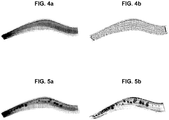
- Such a mapping carried out at a leading edge of a turbomachine blade, is represented in figure 4a .
- the darker areas correspond to areas where the amplitude of the transmitted ultrasound beam is low, that is to say where the attenuation is great.
- the reduction in the amplitude of the ultrasound beam depends both on the thickness of the material passed through and on any defects encountered; for example, if a cavity is in the inspected object, on the path of the ultrasound beam, the ultrasound beam is not transmitted through this cavity, and the amplitude transmitted at this cavity is therefore very reduced compared to the initial emission amplitude.
- the inspected object has a complex geometry, which is the case for example of turbine engine blades, or of blade housings, it is therefore impossible, with the method of inspection by transmission of ultrasound, to differentiate between an area with a defect and an area where the thickness of material to pass through is important, or even a misalignment of the probes due to the geometry of the part.
- the left part of the figure corresponds to the root of the blade and the right part corresponds to the head of the blade, this blade being represented on the figure 1 .
- the left end of the cartography on the figure 5a corresponding to the root of the vane has a dark coloration, indicating a strong absorption of ultrasound at this level of the vane.
- this strong absorption can be linked to a defect in this root or result from the thickness of the blade at this level, but it is not possible to determine it with this mapping.
- a method could include multiple scans of the same part with ultrasound beams having a different gain at each scan and each step.
- this process would waste too much time.
- the object of the invention is to provide a method for inspecting an object making it possible to immediately identify defects present in the structure of the object.
- Another object of the invention is to be able to be used whatever the geometry of the inspected object.
- the invention also relates to a use of the inspection method for inspecting a blade, in particular a blade formed of a composite material and further comprising a metal reinforcement bonded to its leading edge, said method making it possible to detect any gluing anomalies or for the inspection of a blading housing.
- the proposed inspection method makes it possible to do away with the geometry of an object, so that the reductions in energy represented on the map resulting from the inspection are linked only to structural defects of the object.
- the fact of using a reference part, which is known to be free from defects makes it possible to adapt the gain of the reception signal of the ultrasound beam to the thickness of the object inspected at the level from the point of exposure.
- the amplitude of the ultrasound beam is modified so that the object appears to have a constant thickness. It follows that the transmitted amplitude variations can only come from defects of the inspected object, the variations related to the thickness of the object being eliminated.
- This method therefore makes it possible to inspect parts with complex geometry more quickly and with improved reliability.
- FIG. 2 there is schematically shown a system 100 for inspecting an object O by transmission of ultrasound used for implementing the method described below.
- This system comprises a probe 110 for emitting an ultrasound beam, which is moved along a predetermined path by means 120 for controlling the scanning of said probe.
- the receiver 130 On the other side of the probed object O is positioned the receiver 130.
- the probe 110 and the receiver 130 are piezoelectric transducers, able to convert an electrical signal into a mechanical wave and vice versa. Therefore, the roles of the probe and the receptor can be reversed.
- the probe is electrically excited by a signal supplied by a generator 141 of a processing unit 140 to emit ultrasonic waves, and the receiver 130 converts the ultrasonic waves having propagated through the object being probed. into an electrical signal.
- the amplitude of the ultrasound beam transmitted through the object is measured as follows.
- the electrical signal converted by the receiver is transmitted to the processing unit 140, which includes an amplifier 142 to amplify the electrical signal with a desired gain, said gain corresponding to an amplitude gain of the ultrasound beam transmitted through the object O.
- the processing unit further comprises a control unit 143, which can advantageously be a processor, which then measures the amplitude of the electrical signal thus amplified, said amplitude corresponding to the amplitude of the ultrasound beam.
- the control unit 143 is further adapted to associate with each point of the scan of the object probed the amplitude of the ultrasound beam transmitted through the object at said point of the scan.
- the word "mapping” is understood to mean this linking of the points with the respective amplitude, whether or not it is followed by a display of the two-dimensional object representing each point of the scan in one. particular color depending on its transmitted amplitude.
- the inspection system 100 further comprises a display 150 making it possible to represent said map.
- the control unit 142 is also suitable for controlling the gain provided by the amplifier 142 to the ultrasound beam received by the receiver 130, as will be seen below.
- This method comprises the implementation of an object control by ultrasound transmission of the “C-Scan” type, comprising a first measurement step, during which an object to be inspected is scanned with a beam.
- ultrasound by amplifying the signal received from the ultrasound transmitted through the object a determined gain, and measuring the amplitude of the ultrasound beam transmitted through the object after amplification, and a second interpretation step , during which, from these amplitude measurements, a two-dimensional mapping of the object is established, this mapping being a projection of the inspected object along the direction of exposure of the ultrasound beam.
- the object is represented therein in colors or in shades of gray, each point of the map being associated, by its color, with the amplitude of the ultrasound beam transmitted through said object.
- This check is first implemented on a reference part during an initialization step 1000, to deduce therefrom, for this part, the gain corrections of the transmitted signal to be made to the gain of the amplifier 142, so that the amplitude of the ultrasound transmitted through said part is constant.
- the method comprises a step of inspection 2000 proper of each object O to be inspected, comprising the implementation of a “C-Scan” type control using the gain corrected from the corrections as ultrasound reception gain. determined during the initialization step.
- the reference part is a part with the same geometry, ie the same dimensions, as the object to be inspected.
- the object to be inspected is a turbine engine blade
- the reference part is a blade of the same design.
- the reference part must have been selected and checked by other means to verify that it does not contain any defect.
- the reference part is scanned by an ultrasound beam emitted by the probe with a predetermined amplitude A s .
- the receiver receives the ultrasound beam and transmits an electrical signal corresponding to the processing unit.
- the control unit 143 of the processing unit measures the transmitted amplitude A t of the ultrasound for a predetermined reference gain P ref of the amplifier 142 through said part at each point of the scan and in deduced during a sub-step 1200 a map associating with each point of the scan the amplitude transmitted at said point.
- the control unit determines during a sub-step 1300, at each point of the scan, the amplification gain of the received energy G c which should be selected so that the amplitude of the ultrasound transmitted through said part is constant for all the points of the scan, and deduces therefrom a list of corrections to be made to the reference gain G ref at each point of the scan in order to obtain the corrected gain G c .
- This determination of the gain corrections can be performed after the entire part scan has been completed. Alternatively, and preferably, the determination of the gain corrections can be carried out in real time, that is to say that the determination and application of a gain correction to be made to the reference gain G ref at level d A point of the scanning of the part is determined at the time of scanning of said point by the control unit 143.
- the constant amplitude A c transmitted with the corrected gain is preferably greater than 60% of the amplitude A s of the ultrasounds emitted by the probe, to then allow good resolution of the data acquired.
- the amplitude with the corrected gain is between 70 and 90% of the amplitude A s of the ultrasound emitted, and preferably of the order of 80%. This represents a good compromise between the amplitude and the resolution obtained.
- figure 4a a map obtained for the reference part by applying the reference gain G ref of the ultrasound, and by figure 4b the corrected gain G c . It is clearly observed on the map that the variations in the transmitted amplitude due to the variations in thickness of the part are suppressed, and that the transmitted amplitude A c after correction is constant.
- this object must have the same geometry and the same structure as the reference part, for the list of corrections established for the sweep points to be valid.
- the object is scanned by an ultrasound beam, the gain of which at each point of the scan is the corrected gain G c , that is to say the reference gain G ref to which the corrections determined above have been added.
- the receiver picks up the ultrasonic beam and the control unit measures the amplitude of the amplified signal with the corrected gain.
- the control unit 143 performs a mapping of the probed object, by associating with each point of the scan the amplitude of the ultrasound transmitted through the object and received by the receiver.
- this mapping is represented on the display during a step 2300, each point of the scan being represented with a color or a shade of gray representative of the attenuation rate of the transmitted amplitude, or of the transmitted amplitude. herself.
- This turbomachine blade 10 is made of a composite material and has a metal reinforcement 11 on its leading edge, as shown in figure 1 .
- the inspection method is used in particular to identify bonding defects of the reinforcement on the leading edge.
- bonding defects were simulated in the tested blade of the figures 5a and 5b by positioning inserts in absorbent material between the leading edge of the blade and the metal reinforcement.
- the analysis of the map obtained, carried out during a step 2400, either by an operator or automatically, for example by setting up a transmitted amplitude threshold and comparing the values acquired at the different points of the scanning with respect to said threshold, makes it possible to detect or visualize very easily in the figures anomalies from the amplitude transmitted through the part which may correspond to defects in the internal structure of the objects examined. This method therefore makes it possible to identify faults more quickly than the methods proposed so far.
- the inspection step 2000 can therefore be repeated for each new object to be inspected, without having to repeat the step 1000, as shown in the figure. figure 3 with steps 2000 'and 2000 ".
- the reference part and the inspected object are axisymmetric, that is to say symmetrical of revolution about an axis, their surface thus resulting from the revolution of a line around the axis of symmetry.
- This is the case, for example, of a turbomachine blading housing.
- step 1000 for initializing the method can be simplified by determining a list of gain corrections to be made. only for a radial profile of the part, these gain corrections being transposable to the entire circumference of the part.
- the direction of exposure of the ultrasound beam is radial with respect to the axis of symmetry, and the reference part is scanned along a line of said part at the intersection of the surface of the reference part with a radial plane.
- the reference part is scanned along a single line, but the scanning can also be repeated over several lines to check the gain corrections obtained.
- the whole of the axisymmetric object to be inspected is probed according to scanning lines of the ultrasound beam identical to the scanning line carried out to establish the corrections of gain, by applying the corresponding correction to each point of said line.
- the method is particularly suitable for the inspection of turbine engine blading housings made of composite material, to detect porosity and delamination type defects in the material, including at the level of the flange allowing the housing to be fixed to other elements. of the turbomachine, this flange having a bulk making it impossible to inspect it in the small radius (angle of 90 °) and causing misalignment of the probes leading to loss of the signal.
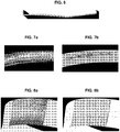
- FIG. 8a and 8b there is shown a map obtained for the casing, at the level of the flow of the latter, before and after application of the gain corrections.
- the square defects in the housing structure are also much more visible.
- the method of inspecting objects proposed is in no way limited to one type of object to be inspected in particular, but advantageously applies to turbine engine blades or to turbomachine blading housings, or to any other object. presenting a complex geometry with many variations in thickness.
- the invention is applicable to any object made of a material exhibiting a high rate of absorption of ultrasound such as a composite material, and in particular in a 3D woven or 3D interlock composite material, that is to say ie comprising a reinforcing structure taken from a matrix, for example made of polymer material.
- the method therefore makes it possible to easily check these objects, and even to immediately visualize the faults which they may contain.
Landscapes
- Physics & Mathematics (AREA)
- General Physics & Mathematics (AREA)
- Analytical Chemistry (AREA)
- Health & Medical Sciences (AREA)
- Life Sciences & Earth Sciences (AREA)
- Chemical & Material Sciences (AREA)
- Biochemistry (AREA)
- General Health & Medical Sciences (AREA)
- Immunology (AREA)
- Pathology (AREA)
- Engineering & Computer Science (AREA)
- Signal Processing (AREA)
- Acoustics & Sound (AREA)
- Investigating Or Analyzing Materials By The Use Of Ultrasonic Waves (AREA)
Description
L'invention concerne le domaine des procédés d'inspections non destructives d'objets par transmission d'ultrasons pour y déceler des anomalies internes, tels que des porosités, délaminages, fissures,... présentes dans le volume de l'objet inspecté ou des défauts de collage dans le cas où l'objet inspecté est formé par l'association de plusieurs pièces.The invention relates to the field of non-destructive inspection methods of objects by ultrasound transmission to detect internal anomalies, such as porosities, delaminations, cracks, etc. present in the volume of the inspected object or gluing defects in the event that the inspected object is formed by the association of several parts.
L'invention s'applique notamment à l'inspection de pièces à géométrie complexe telles que des aubes et des carters d'aubes de turbomachines.The invention applies in particular to the inspection of parts with a complex geometry, such as blades and turbine engine blade housings.
On connaît déjà différentes techniques de contrôle non destructif par ultrasons. Une technique connue est le contrôle par réflexion, au cours de laquelle on effectue un balayage d'un objet à inspecter avec un faisceau d'ultrasons à un gain déterminé, et on mesure l'amplitude du faisceau réfléchi par l'objet pour détecter d'éventuelles altérations dans la structure interne de l'objet.Various techniques of non-destructive testing by ultrasound are already known. A known technique is the inspection by reflection, during which a scanning of an object to be inspected is carried out with an ultrasound beam at a determined gain, and the amplitude of the beam reflected by the object is measured in order to detect d 'possible alterations in the internal structure of the object.
Cependant, le procédé de contrôle par réflexion d'ultrasons n'est pas adapté pour des objets réalisés en un matériau absorbant fortement les ultrasons, tel que par exemple les matériaux composites. Or on a désormais recours aux matériaux composites pour fabriquer des éléments de turbomachines, comme par exemple des aubes ou des carters d'aubes.However, the ultrasound reflection test method is not suitable for objects made of a material which strongly absorbs ultrasound, such as for example composite materials. Now, use is made of composite materials to manufacture components of turbomachines, such as, for example, blades or blade housings.
Dans ce cas, un procédé d'inspection plus adapté est le contrôle ultrasons par transmission en utilisant la représentation de type « C-Scan ».Cela implique un accès à deux faces opposées de la pièce à contrôler. Le récepteur est alors disposé en face de l'émetteur et il recueille l'énergie qui a été transmise à travers la pièce. Les réflecteurs tels que les interfaces ou anomalies, seront détectés par une diminution de cette énergie, mais il n'est pas possible de les localiser dans l'épaisseur de la pièce.In this case, a more suitable inspection method is ultrasonic transmission inspection using the “C-Scan” type representation. This implies access to two opposite sides of the part to be inspected. The receiver is then placed in front of the transmitter and it collects the energy which has been transmitted through the room. Reflectors such as interfaces or anomalies will be detected by a decrease in this energy, but it is not possible to locate them in the thickness of the part.
A partir de cette mesure d'amplitude, on réalise ensuite une cartographie représentant une projection de l'objet inspecté selon la direction du faisceau d'ultrasons, dont chaque point est coloré en fonction de l'amplitude. Une telle cartographie, réalisée au niveau d'un bord d'attaque d'aube de turbomachine, est représentée en
Or, la diminution de l'amplitude du faisceau d'ultrasons dépend à la fois de l'épaisseur de matériau traversé et des défauts éventuellement rencontrés ; par exemple, si une cavité se trouve dans l'objet inspecté, sur la trajectoire du faisceau d'ultrasons, le faisceau d'ultrasons n'est pas transmis au travers de cette cavité, et l'amplitude transmise au niveau de cette cavité est donc très diminuée par rapport à l'amplitude d'émission initiale.However, the reduction in the amplitude of the ultrasound beam depends both on the thickness of the material passed through and on any defects encountered; for example, if a cavity is in the inspected object, on the path of the ultrasound beam, the ultrasound beam is not transmitted through this cavity, and the amplitude transmitted at this cavity is therefore very reduced compared to the initial emission amplitude.
Dans le cas où l'objet inspecté présente une géométrie complexe, ce qui est le cas par exemple d'aubes de turbomachines, ou de carters d'aubes, il est donc impossible, avec le procédé d'inspection par transmission d'ultrasons, de faire la différence entre une zone présentant un défaut et une zone où l'épaisseur de matériau à traverser est importante, ou encore un désalignement des sondes dû à la géométrie de la pièce.In the case where the inspected object has a complex geometry, which is the case for example of turbine engine blades, or of blade housings, it is therefore impossible, with the method of inspection by transmission of ultrasound, to differentiate between an area with a defect and an area where the thickness of material to pass through is important, or even a misalignment of the probes due to the geometry of the part.
Par exemple, sur la
Par ailleurs le document
Il existe donc un besoin pour un procédé d'inspection d'un objet permettant de s'affranchir de la complexité de la géométrie de l'objet inspecté, et permettant d'identifier des défauts dans la structure de l'objet inspecté indépendamment de l'épaisseur de l'objet.There is therefore a need for a method of inspecting an object making it possible to overcome the complexity of the geometry of the inspected object, and making it possible to identify defects in the structure of the inspected object regardless of the size. thickness of the object.
Pour ce faire, un procédé pourrait comprendre des balayages multiples d'une même pièce avec des faisceaux d'ultrasons présentant à chaque balayage et chaque pas un gain différent. Cependant, puisque toutes les pièces doivent être inspectées avant d'être utilisées, ce procédé engendrerait une perte de temps trop importante.To do this, a method could include multiple scans of the same part with ultrasound beams having a different gain at each scan and each step. However, since all parts must be inspected before use, this process would waste too much time.
L'invention a pour but de proposer un procédé d'inspection d'un objet permettant d'identifier immédiatement des défauts présents dans la structure de l'objet.The object of the invention is to provide a method for inspecting an object making it possible to immediately identify defects present in the structure of the object.
Un autre but de l'invention est de pouvoir être utilisée quelle que soit la géométrie de l'objet inspecté.Another object of the invention is to be able to be used whatever the geometry of the inspected object.
A cet égard, l'invention a pour objet un procédé d'inspection d'un objet par transmission d'ultrasons, dans lequel on met en oeuvre un balayage dudit objet par un faisceau d'ultrasons et une mesure de l'amplitude du faisceau d'ultrasons transmis à travers ledit objet, ladite mesure comprenant la conversion du faisceau d'ultrasons en signal électrique, l'application d'un gain d'amplification audit signal et la mesure de l'amplitude dudit signal, afin d'en déduire une cartographie dans laquelle chaque point d'une surface de projection dudit objet selon la direction d'exposition est associé à l'amplitude du faisceau d'ultrasons transmise audit point à travers ledit objet, le procédé comprenant les étapes consistant à :
- mettre en oeuvre ledit balayage et ladite mesure d'amplitude sur une pièce de référence présentant une géométrie identique à l'objet à inspecter, afin d'en déduire une cartographie de ladite pièce, le gain d'amplification appliqué pour la mesure d'amplitude étant un gain de référence prédéterminé,
- déterminer, pour une pluralité de points de la cartographie de la pièce de référence, des corrections de gain à apporter au gain de référence aux points correspondants du balayage pour obtenir une amplitude du faisceau d'ultrasons transmise à travers la pièce de référence constante pour l'ensemble des points de la cartographie,
- mettre en oeuvre ledit balayage et ladite mesure d'amplitude sur l'objet à inspecter, en appliquant aux différents points du balayage un gain d'amplification correspondant au gain de référence corrigé à partir des corrections de gain précédemment déterminées.
- implementing said scanning and said amplitude measurement on a reference part having a geometry identical to the object to be inspected, in order to deduce therefrom a map of said part, the amplification gain applied for the amplitude measurement being a predetermined reference gain,
- determine, for a plurality of points in the map of the reference part, gain corrections to be made to the reference gain at the corresponding points of the scan to obtain an amplitude of the ultrasound beam transmitted through the reference part constant for l 'all the points of the cartography,
- implementing said scanning and said amplitude measurement on the object to be inspected, by applying to the various points of the scanning an amplification gain corresponding to the reference gain corrected from the gain corrections determined previously.
Avantageusement, mais facultativement, le procédé selon l'invention présente en outre au moins l'une des caractéristiques suivantes :
- on déduit de ladite mesure d'amplitude sur l'objet à inspecter une cartographie de l'objet et on analyse la cartographie ainsi obtenue afin de détecter une éventuelle anomalie quant à l'amplitude transmise à travers l'objet.
- l'objet à inspecter et la pièce de référence sont axisymétriques, la direction d'exposition du faisceau d'ultrasons est radiale par rapport à l'axe de symétrie, et la pièce de référence est balayée selon une ligne de ladite pièce à l'intersection de la surface de la pièce de référence avec un plan radial.
- l'objet à inspecter et la pièce de référence comprennent du matériau composite.
- l'amplitude constante transmise à travers la pièce de référence est supérieure à 60% de l'amplitude du faisceau d'ultrasons émis, et est avantageusement comprise entre 70 et 90% de ladite amplitude, et de préférence égale à 80% de ladite amplitude.
- la correction de gain à apporter au gain de référence en un point du balayage est déterminée simultanément au balayage du point correspondant de la pièce de référence.
- from said amplitude measurement on the object to be inspected, a mapping of the object is deduced and the mapping thus obtained is analyzed in order to detect any anomaly as to the amplitude transmitted through the object.
- the object to be inspected and the reference part are axisymmetric, the direction of exposure of the ultrasound beam is radial with respect to the axis of symmetry, and the reference part is scanned along a line from said part to the intersection of the reference part surface with a radial plane.
- the object to be inspected and the reference part consist of composite material.
- the constant amplitude transmitted through the reference part is greater than 60% of the amplitude of the ultrasound beam emitted, and is advantageously between 70 and 90% of said amplitude, and preferably equal to 80% of said amplitude .
- the gain correction to be made to the reference gain at a point of the scan is determined simultaneously with the scan of the corresponding point of the reference part.
L'invention porte également sur une utilisation du procédé d'inspection pour l'inspection d'une aube, notamment une aube formée en matériau composite et comprenant en outre un renfort en métal collé sur son bord d'attaque, ledit procédé permettant de détecter d'éventuelles anomalies de collage ou encore pour l'inspection d'un carter d'aubage.The invention also relates to a use of the inspection method for inspecting a blade, in particular a blade formed of a composite material and further comprising a metal reinforcement bonded to its leading edge, said method making it possible to detect any gluing anomalies or for the inspection of a blading housing.
L'invention a également pour objet un système d'inspection d'un objet par transmission d'ultrasons, pour la mise en oeuvre du procédé d'inspection qui précède, comprenant :
- une sonde d'émission d'un faisceau d'ultrasons et des moyens de pilotage du balayage de la sonde, adaptés pour mettre en oeuvre un balayage dudit objet par un faisceau d'ultrasons émis par la sonde,
- un récepteur d'ultrasons, adapté pour convertir le faisceau d'ultrasons transmis à travers ledit objet en signal électrique, et
- une unité de traitement, comprenant un amplificateur adapté pour appliquer un gain d'amplification au signal électrique obtenu par le récepteur, et une unité de commande configurée pour mesurer l'amplitude du signal amplifié et pour déduire de ladite mesure d'amplitude une cartographie dans laquelle chaque point d'une surface de projection dudit objet selon la direction d'exposition est associé à l'amplitude transmise audit point à travers ledit objet,
et pour commander l'amplificateur afin d'appliquer, lors du balayage et de ladite mesure d'amplitude sur l'objet à inspecter, aux différents points du balayage du faisceau d'ultrasons, un gain d'amplification correspondant au gain de référence corrigé en fonction des corrections de gain ainsi déterminées.The subject of the invention is also a system for inspecting an object by transmission of ultrasound, for implementing the above inspection method, comprising:
- a probe for emitting an ultrasound beam and means for controlling the scanning of the probe, adapted to carry out a scanning of said object by an ultrasound beam emitted by the probe,
- an ultrasound receiver, adapted to convert the ultrasound beam transmitted through said object into an electrical signal, and
- a processing unit, comprising an amplifier adapted to apply an amplification gain to the electrical signal obtained by the receiver, and a control unit configured to measure the amplitude of the amplified signal and to deduce from said amplitude measurement a map in in which each point of a projection surface of said object in the direction of exposure is associated with the amplitude transmitted to said point through said object,
and to control the amplifier so as to apply, during the scanning and said amplitude measurement on the object to be inspected, to the various points of the scanning of the ultrasound beam, an amplification gain corresponding to the corrected reference gain as a function of the gain corrections thus determined.
Le procédé d'inspection proposé permet de s'affranchir de la géométrie d'un objet, pour que des diminutions d'énergie représentées sur la cartographie résultant de l'inspection ne soient liées qu'à des défauts structuraux de l'objet.The proposed inspection method makes it possible to do away with the geometry of an object, so that the reductions in energy represented on the map resulting from the inspection are linked only to structural defects of the object.
En effet, le fait d'utiliser une pièce de référence, dont on sait qu'elle est exempte de défauts, permet d'adapter le gain du signal de réception du faisceau d'ultrasons à l'épaisseur de l'objet inspecté au niveau du point d'exposition. Ainsi, l'amplitude du faisceau d'ultrasons est modifiée pour que l'objet paraisse présenter une épaisseur constante. Il en résulte que les variations d'amplitude transmise ne peuvent provenir que de défauts de l'objet inspecté, les variations liées à l'épaisseur de l'objet étant supprimées.Indeed, the fact of using a reference part, which is known to be free from defects, makes it possible to adapt the gain of the reception signal of the ultrasound beam to the thickness of the object inspected at the level from the point of exposure. Thus, the amplitude of the ultrasound beam is modified so that the object appears to have a constant thickness. It follows that the transmitted amplitude variations can only come from defects of the inspected object, the variations related to the thickness of the object being eliminated.
Ce procédé permet donc d'inspecter plus rapidement et avec une fiabilité améliorée des pièces présentant une géométrie complexe.This method therefore makes it possible to inspect parts with complex geometry more quickly and with improved reliability.
D'autres caractéristiques, buts et avantages de la présente invention apparaîtront à la lecture de la description détaillée qui va suivre, au regard des figures annexées, données à titre d'exemples non limitatifs et sur lesquelles :
- La
figure 1 , déjà décrite, représente une aube de turbomachine, - La
figure 2 représente schématiquement un système d'inspection par transmission d'ultrasons, - La
figure 3 représente les principales étapes d'un procédé d'inspection par transmission d'ultrasons, - Les
figures 4a et 4b représentent respectivement les cartographies d'une aube de référence obtenues avant et après correction du gain du signal de réception des ultrasons, - Les
figures 5a et 5b (lafigure 5a étant déjà décrite) représentent respectivement les cartographies d'une aube inspectée obtenues avant et après correction du gain du signal de réception des ultrasons, - La
figure 6 représente un profil axial d'un carter d'aubage de turbomachine, - Les
figures 7a et 7b représentent respectivement les cartographies d'une bride de carter d'aubage obtenues avant et après correction du gain du signal de réception des ultrasons, - Les
figures 8a et 8b représentent respectivement les cartographies d'un carter d'aubage inspecté obtenues avant et après correction du gain du signal de réception des ultrasons.
- The
figure 1 , already described, represents a turbine engine blade, - The
figure 2 schematically represents an inspection system by transmission of ultrasound, - The
figure 3 represents the main stages of an ultrasound transmission inspection process, - The
figures 4a and 4b respectively represent the maps of a reference vane obtained before and after correction of the gain of the ultrasound reception signal, - The
figures 5a and 5b (thefigure 5a being already described) respectively represent the maps of an inspected blade obtained before and after correction of the gain of the ultrasound reception signal, - The
figure 6 shows an axial profile of a turbomachine blade casing, - The
figures 7a and 7b respectively represent the maps of a blading housing flange obtained before and after correction of the gain of the ultrasound reception signal, - The
figures 8a and 8b respectively represent the maps of an inspected blade casing obtained before and after correction of the gain of the ultrasound reception signal.
En référence à la
Ce système comprend une sonde 110 d'émission d'un faisceau d'ultrasons, qui est déplacée selon un trajet prédéterminé par des moyens de pilotage 120 du balayage de ladite sonde.This system comprises a
De l'autre côté de l'objet O sondé est positionné le récepteur 130.On the other side of the probed object O is positioned the
La sonde 110 et le récepteur 130 sont des transducteurs piézoélectriques, aptes à convertir un signal électrique en onde mécanique et réciproquement. Par conséquent, les rôles de la sonde et du récepteur peuvent être inversés.The
En l'occurrence, la sonde est excitée électriquement par un signal fourni par un générateur 141 d'une unité de traitement 140 pour émettre des ondes ultrasonores, et le récepteur 130 convertit les ondes ultrasonores s'étant propagées au travers de l'objet sondé en un signal électrique.In this case, the probe is electrically excited by a signal supplied by a
L'amplitude du faisceau d'ultrasons transmis à travers l'objet est mesurée comme suit. Le signal électrique converti par le récepteur est transmis à l'unité de traitement 140, qui comporte un amplificateur 142 pour amplifier le signal électrique avec un gain voulu, ledit gain correspondant à un gain en amplitude du faisceau d'ultrasons transmis à travers l'objet O. L'unité de traitement comporte en outre une unité de commande 143, pouvant être avantageusement un processeur, qui mesure ensuite l'amplitude du signal électrique ainsi amplifié, ladite amplitude correspondant à l'amplitude du faisceau d'ultrasons.The amplitude of the ultrasound beam transmitted through the object is measured as follows. The electrical signal converted by the receiver is transmitted to the processing unit 140, which includes an
L'unité de commande 143 est en outre adaptée pour associer à chaque point du balayage de l'objet sondé l'amplitude du faisceau d'ultrasons transmis à travers l'objet au niveau dudit point du balayage. Dans la présente, on entend par le mot « cartographie » cette mise en relation des points avec l'amplitude respective, qu'elle soit ou non suivie d'un affichage de l'objet en deux-dimensions représentant chaque point du balayage en une couleur particulière dépendant de son amplitude transmise.The
Avantageusement, mais facultativement, le système d'inspection 100 comprend en outre un afficheur 150 permettant de représenter ladite cartographie.Advantageously, but optionally, the inspection system 100 further comprises a
L'unité de commande 142 est également adaptée pour commander le gain apporté par l'amplificateur 142 au faisceau d'ultrasons reçu par le récepteur 130, comme on va le voir ci-après.The
En référence à la
Ce procédé comprend la mise en oeuvre d'un contrôle d'objet par transmission d'ultrasons de type « C-Scan », comprenant une première étape de mesure, au cours de laquelle on balaye un objet à inspecter avec un faisceau d'ultrasons, en amplifiant le signal reçu à partir des ultrasons transmis à travers l'objet un gain déterminé, et on mesure l'amplitude du faisceau d'ultrasons transmis à travers l'objet après amplification, et une seconde étape d'interprétation, au cours de laquelle, à partir de ces mesures d'amplitude, on établit une cartographie de l'objet en deux-dimensions, cette cartographie étant une projection de l'objet inspecté selon la direction d'exposition du faisceau d'ultrasons. L'objet y est représenté en couleurs ou en nuances de gris, chaque point de la cartographie étant associé, par sa couleur, à l'amplitude du faisceau d'ultrasons transmise à travers ledit objet.This method comprises the implementation of an object control by ultrasound transmission of the “C-Scan” type, comprising a first measurement step, during which an object to be inspected is scanned with a beam. ultrasound, by amplifying the signal received from the ultrasound transmitted through the object a determined gain, and measuring the amplitude of the ultrasound beam transmitted through the object after amplification, and a second interpretation step , during which, from these amplitude measurements, a two-dimensional mapping of the object is established, this mapping being a projection of the inspected object along the direction of exposure of the ultrasound beam. The object is represented therein in colors or in shades of gray, each point of the map being associated, by its color, with the amplitude of the ultrasound beam transmitted through said object.
Ce contrôle est d'abord mis en oeuvre sur une pièce de référence au cours d'une étape d'initialisation 1000, pour en déduire, pour cette pièce, des corrections de gain du signal transmis à apporter au gain de l'amplificateur 142, afin que l'amplitude des ultrasons transmis à travers ladite pièce soit constante.This check is first implemented on a reference part during an
Puis le procédé comprend une étape d'inspection 2000 proprement dite de chaque objet O à inspecter, comprenant la mise en oeuvre d'un contrôle de type « C-Scan » en utilisant comme gain de réception des ultrasons le gain corrigé à partir des corrections déterminées lors de l'étape d'initialisation.Then the method comprises a step of
On va maintenant décrire de manière détaillée l'étape d'initialisation 1000 réalisée sur une pièce de référence.We will now describe in detail the
La pièce de référence est une pièce présentant la même géométrie, c'est-à-dire les mêmes dimensions, que l'objet à inspecter. Par exemple, si l'objet à inspecter est une aube de turbomachine, la pièce de référence est une aube de même conception.The reference part is a part with the same geometry, ie the same dimensions, as the object to be inspected. For example, if the object to be inspected is a turbine engine blade, the reference part is a blade of the same design.
De plus la pièce de référence doit avoir été sélectionnée et contrôlée par d'autres moyens pour vérifier qu'elle ne comporte pas de défaut.In addition, the reference part must have been selected and checked by other means to verify that it does not contain any defect.
Au cours d'une première sous-étape 1100, la pièce de référence est balayée par un faisceau d'ultrasons émis par la sonde avec une amplitude As prédéterminée.During a first sub-step 1100, the reference part is scanned by an ultrasound beam emitted by the probe with a predetermined amplitude A s .
Le récepteur reçoit le faisceau d'ultrasons et transmet un signal électrique correspondant à l'unité de traitement.The receiver receives the ultrasound beam and transmits an electrical signal corresponding to the processing unit.
L'unité de commande 143 de l'unité de traitement mesure l'amplitude transmise At des ultrasons pour un gain de référence Pref prédéterminé de l'amplificateur 142 au travers de ladite pièce en chaque point du balayage et en déduit au cours d'une sous-étape 1200 une cartographie associant à chaque point du balayage l'amplitude transmise au niveau dudit point.The
L'unité de commande détermine alors au cours d'une sous-étape 1300, en chaque point du balayage, le gain d'amplification de l'énergie reçue Gc qui devrait être sélectionné pour que l'amplitude des ultrasons transmis à travers ladite pièce soit constante pour tous les points du balayage, et en déduit une liste de corrections à apporter au gain de référence Gref en chaque point du balayage pour obtenir le gain corrigé Gc.The control unit then determines during a sub-step 1300, at each point of the scan, the amplification gain of the received energy G c which should be selected so that the amplitude of the ultrasound transmitted through said part is constant for all the points of the scan, and deduces therefrom a list of corrections to be made to the reference gain G ref at each point of the scan in order to obtain the corrected gain G c .
Cette détermination des corrections de gain peut être réalisée une fois que l'ensemble du balayage de la pièce a été réalisé. Alternativement, et de préférence, la détermination des corrections de gain peut être réalisée en temps réel, c'est-à-dire que la détermination et l'application d'une correction de gain à apporter au gain de référence Gref au niveau d'un point du balayage de la pièce est déterminée au moment du balayage dudit point par l'unité de commande 143.This determination of the gain corrections can be performed after the entire part scan has been completed. Alternatively, and preferably, the determination of the gain corrections can be carried out in real time, that is to say that the determination and application of a gain correction to be made to the reference gain G ref at level d A point of the scanning of the part is determined at the time of scanning of said point by the
L'amplitude constante Ac transmise avec le gain corrigé est de préférence supérieure à 60% de l'amplitude As des ultrasons émis par la sonde, pour permettre ensuite une bonne résolution des données acquises. Avantageusement, l'amplitude avec le gain corrigé est comprise entre 70 et 90% de l'amplitude As des ultrasons émis, et préférablement de l'ordre de 80%. Ceci représente un bon compromis entre l'amplitude et la résolution obtenue.The constant amplitude A c transmitted with the corrected gain is preferably greater than 60% of the amplitude A s of the ultrasounds emitted by the probe, to then allow good resolution of the data acquired. Advantageously, the amplitude with the corrected gain is between 70 and 90% of the amplitude A s of the ultrasound emitted, and preferably of the order of 80%. This represents a good compromise between the amplitude and the resolution obtained.
Ainsi on obtient un tableau analogue à celui représenté ci-après, dans lequel on associe à chaque point du balayage une correction de gain en fonction de l'amplitude transmise lors du contrôle de la pièce de référence :
Le fait d'obtenir une amplitude transmise corrigée Ac constante pour la pièce de référence permet de s'affranchir des variations d'épaisseur de la pièce au niveau des différents points de balayage. Par conséquent, en appliquant ultérieurement un gain corrigé Gc à partir desdites corrections sur un objet à contrôler présentant la même géométrie que la pièce de référence, les seules variations de l'amplitude transmise résulteront directement de défauts dans la structure de l'objet contrôlé.The fact of obtaining a constant corrected transmitted amplitude A c for the reference part makes it possible to overcome variations in the thickness of the part at the various scanning points. Consequently, by subsequently applying a corrected gain G c from said corrections to an object to be inspected having the same geometry as the reference part, the only variations in the amplitude transmitted will result directly from defects in the structure of the object being tested .
On a représenté en
De retour à la
Comme indiqué précédemment, cet objet doit présenter la même géométrie et la même structure que la pièce de référence, pour que la liste des corrections établie pour les points de balayage soit valable.As indicated previously, this object must have the same geometry and the same structure as the reference part, for the list of corrections established for the sweep points to be valid.
Au cours d'une sous-étape 2100, l'objet est balayé par un faisceau d'ultrasons, dont le gain en chaque point du balayage est le gain corrigé Gc, c'est-à-dire le gain de référence Gref auquel on a ajouté les corrections déterminées ci-avant.During a sub-step 2100, the object is scanned by an ultrasound beam, the gain of which at each point of the scan is the corrected gain G c , that is to say the reference gain G ref to which the corrections determined above have been added.
Le récepteur capte le faisceau ultrasonore et l'unité de commande mesure l'amplitude du signal amplifié avec le gain corrigé.The receiver picks up the ultrasonic beam and the control unit measures the amplitude of the amplified signal with the corrected gain.
Au cours d'une sous-étape 2200, l'unité de commande 143 réalise une cartographie de l'objet sondé, en associant à chaque point du balayage l'amplitude des ultrasons transmis à travers l'objet et reçus par le récepteur. Avantageusement, cette cartographie est représentée sur l'afficheur au cours d'une étape 2300, chaque point du balayage étant représenté avec une couleur ou une nuance de gris représentative du taux d'atténuation de l'amplitude transmise, ou de l'amplitude transmise elle-même.During a sub-step 2200, the
On a représenté en
Cette aube de turbomachine 10 est réalisée en matériau composite et présente un renfort métallique 11 sur son bord d'attaque, comme représenté sur la
On observe sur la
L'analyse de la cartographie obtenue, réalisée au cours d'une étape 2400, soit par un opérateur, soit de manière automatique, par exemple par mise en place d'un seuil d'amplitude transmise et comparaison des valeurs acquises aux différents points du balayage par rapport audit seuil, permet de détecter ou de visualiser très facilement sur les figures des anomalies à partir de l'amplitude transmise à travers la pièce pouvant correspondre à des défauts dans la structure interne des objets examinés. Ce procédé permet donc de repérer des défauts plus rapidement que les procédés proposés jusqu'à présent.The analysis of the map obtained, carried out during a
De plus, une fois l'établissement des corrections de gain réalisées pour une géométrie donnée, ces corrections sont applicables à toutes les pièces de même géométrie. L'étape d'inspection 2000 peut donc être répétée pour chaque nouvel objet à inspecter, sans avoir besoin de réitérer l'étape 1000, comme représenté sur la
Selon un mode de réalisation particulier, la pièce de référence et l'objet inspecté sont axisymétriques, c'est-à-dire symétrique de révolution autour d'un axe, leur surface résultant ainsi de la révolution d'une ligne autour de l'axe de symétrie. C'est le cas par exemple d'un carter d'aubage de turbomachine.According to a particular embodiment, the reference part and the inspected object are axisymmetric, that is to say symmetrical of revolution about an axis, their surface thus resulting from the revolution of a line around the axis of symmetry. This is the case, for example, of a turbomachine blading housing.
Les variations d'épaisseur d'une telle pièce dans la direction radiale autour de l'axe sont donc identiques sur toute la circonférence de la pièce. On a à cet égard illustré en
Dans ce cas, on peut simplifier la mise en oeuvre de l'étape 1000 d'initialisation du procédé en déterminant une liste de corrections de gain à apporter seulement pour un profil radial de la pièce, ces corrections de gain étant transposables à toute la circonférence de la pièce.In this case, the implementation of
Par conséquent, au cours de l'étape 1100 de balayage de la pièce de référence par un faisceau d'ultrasons, la direction d'exposition du faisceau d'ultrasons est radiale par rapport à l'axe de symétrie, et la pièce de référence est balayée selon une ligne de ladite pièce à l'intersection de la surface de la pièce de référence avec un plan radial. Avantageusement, la pièce de référence est balayée selon une unique ligne, mais on peut également réitérer le balayage sur plusieurs lignes pour vérifier les corrections de gain obtenues.Therefore, during
Ensuite, lors de l'étape 2000 d'inspection de l'objet, l'ensemble de l'objet axisymétrique à inspecter est sondé selon des lignes de balayage du faisceau d'ultrasons identiques à la ligne de balayage réalisée pour établir les corrections de gain , en appliquant à chaque point de ladite ligne la correction correspondante.Then, during the
Le procédé est particulièrement adapté à l'inspection de carters d'aubage de turbomachine en matériau composite, pour détecter des défauts de type porosités et délaminages dans le matériau, y compris au niveau de la bride permettant de fixer le carter à d'autres éléments de la turbomachine, cette bride présentant un encombrement rendant impossible son inspection dans le rayon faible (angle de 90°) et provoquant un désalignement des sondes entrainant une perte du signal.The method is particularly suitable for the inspection of turbine engine blading housings made of composite material, to detect porosity and delamination type defects in the material, including at the level of the flange allowing the housing to be fixed to other elements. of the turbomachine, this flange having a bulk making it impossible to inspect it in the small radius (angle of 90 °) and causing misalignment of the probes leading to loss of the signal.
On a représenté en
De même, sur les
Le procédé d'inspection d'objets proposé n'est nullement limité à un type d'objets à inspecter en particulier, mais s'applique avantageusement à des aubes de turbomachines ou à des carters d'aubage de turbomachine, ou à tout autre objet présentant une géométrie complexe avec de nombreuses variations d'épaisseurs.The method of inspecting objects proposed is in no way limited to one type of object to be inspected in particular, but advantageously applies to turbine engine blades or to turbomachine blading housings, or to any other object. presenting a complex geometry with many variations in thickness.
Plus généralement, l'invention est applicable à tout objet réalisé en matériau présentant un fort taux d'absorption des ultrasons tel qu'en un matériau composite, et en particulier dans un matériau composite tissé 3D ou 3D interlock, c'est-à-dire comprenant une structure de renfort prise dans une matrice, par exemple en matériau polymère.More generally, the invention is applicable to any object made of a material exhibiting a high rate of absorption of ultrasound such as a composite material, and in particular in a 3D woven or 3D interlock composite material, that is to say ie comprising a reinforcing structure taken from a matrix, for example made of polymer material.
Le procédé permet donc de contrôler facilement ces objets, et même de visualiser immédiatement les défauts qu'ils peuvent comporter.The method therefore makes it possible to easily check these objects, and even to immediately visualize the faults which they may contain.
Claims (10)
- An inspection method of an object (O) by ultrasound transmission, wherein a scanning of said object by an ultrasound beam and measurement of the amplitude of the ultrasound beam transmitted via said object (O) are carried out, said measurement comprising conversion of the ultrasound beam into an electrical signal, the application of an amplification gain to said signal and measurement of the amplitude of said signal,
to deduce therefrom a mapping in which each point of a projection surface of said object according to the direction of exposure is associated to the amplitude of the ultrasound beam transmitted to said point via said object, the method comprising the steps consisting of:- carrying out said scanning and said amplitude measurement (1100) on a reference piece having a geometry identical to the object to be inspected, to deduce therefrom (1200) a mapping of said piece associating to each point of the scanning the transmitted amplitude at said point, the amplification gain applied for the amplitude measurement being a predetermined reference gain (Gref),- determining (1300), at each point of the mapping of the reference piece, gain corrections to be made to the reference gain (Gref) at each of the corresponding points of the scanning to obtain a constant amplitude of the ultrasound beam (Ac) transmitted via the reference piece for all the points of the mapping,- carrying out said scanning and said amplitude measurement (2100) on the object to be inspected (O), by applying to the different points of the scanning an amplification gain (Gc) corresponding to the reference gain (Gref) corrected from the gain corrections previously determined. - The method according to claim 1, wherein a mapping of the object (2200) is deduced from said amplitude measurement on the object to be inspected (O) and the resulting mapping is analysed (2300) to detect any anomaly as to the amplitude transmitted via the object.
- The inspection method according to one of the preceding claims, wherein the object to be inspected and the reference piece are axisymmetrical, the direction of exposure of the ultrasound beam is radial relative to the axis of symmetry, and the reference piece is scanned according to a line of said piece at the intersection of the surface of the reference piece with a radial plane.
- The inspection method according to one of the preceding claims, wherein the object to be inspected and the reference piece comprise composite material.
- The inspection method according to one of the preceding claims, wherein the constant amplitude (Ac) transmitted via the reference piece is greater than 60% of the amplitude of the ultrasound beam emitted (As), and is advantageously between 70 and 90% of said amplitude, and preferably equal to 80% of said amplitude.
- The inspection method according to one of the preceding claims, wherein the gain correction to be made to the reference gain (Gref) at a point of the scanning is determined simultaneously with scanning of the corresponding point of the reference piece.
- Use of the method according to one of the preceding claims, for inspection of a blade (10).
- Use of the method according to claim 3, for inspection of a blade casing.
- Use of the method according to one of claims 1 to 6, for the inspection of a blade (10) of a turbomachine fan, said blade being formed from composite material and also comprising a metal reinforcement (11) stuck on its leading edge, said method detecting any adhesion anomalies.
- An inspection system (100) of an object by ultrasound transmission, for carrying out the method according to one of claims 1 to 6, comprising:- an emission probe (110) of an ultrasound beam and control means (120) of the scanning of the probe, adapted for performing scanning of said object by an ultrasound beam emitted by the probe,- an ultrasound receiver (130), adapted to convert the ultrasound beam transmitted via said object into an electrical signal, and- a processing unit (140), comprising an amplifier (142) adapted to apply an amplification gain to the electrical signal obtained by the receiver (130), and a control unit (143) configured to measure the amplitude of the amplified signal and to deduce from said amplitude measurement a mapping in which each point of a projection surface of said object according to the direction of exposure is associated to the amplitude transmitted to said point via said object,the control unit (143) being further adapted to determine, for a plurality of points of a mapping performed from the scanning of a reference piece by an ultrasound beam at a predetermined reference gain (Gref), associating to each point of the scanning the amplitude transmitted at said point, gain corrections to be made to the reference gain (Gref) at each of the corresponding points of the scanning to obtain a constant amplitude (Ac) transmitted via the reference piece for all the points of the mapping,
and to control the amplifier (142) in order to apply, during the scanning and said amplitude measurement on the object to be inspected, to the different points of the scanning of the ultrasound beam, an amplification gain (Gc) corresponding to the reference gain (Gref) corrected as a function of the gain corrections thus determined.
Applications Claiming Priority (2)
| Application Number | Priority Date | Filing Date | Title |
|---|---|---|---|
| FR1354956A FR3006447B1 (en) | 2013-05-30 | 2013-05-30 | ULTRASOUND TRANSMISSION INSPECTION METHOD IMPROVED |
| PCT/FR2014/051202 WO2014191661A1 (en) | 2013-05-30 | 2014-05-22 | Improved method for inspection by the transmission of ultrasounds |
Publications (2)
| Publication Number | Publication Date |
|---|---|
| EP3004864A1 EP3004864A1 (en) | 2016-04-13 |
| EP3004864B1 true EP3004864B1 (en) | 2021-01-13 |
Family
ID=49054754
Family Applications (1)
| Application Number | Title | Priority Date | Filing Date |
|---|---|---|---|
| EP14731705.1A Active EP3004864B1 (en) | 2013-05-30 | 2014-05-22 | Improved method for inspection by the transmission of ultrasounds |
Country Status (9)
| Country | Link |
|---|---|
| US (1) | US10041828B2 (en) |
| EP (1) | EP3004864B1 (en) |
| JP (1) | JP6441321B2 (en) |
| CN (1) | CN105247362B (en) |
| BR (1) | BR112015029618B1 (en) |
| CA (1) | CA2912809C (en) |
| FR (1) | FR3006447B1 (en) |
| RU (1) | RU2639585C2 (en) |
| WO (1) | WO2014191661A1 (en) |
Cited By (1)
| Publication number | Priority date | Publication date | Assignee | Title |
|---|---|---|---|---|
| FR3127813A1 (en) * | 2021-10-05 | 2023-04-07 | Safran Aircraft Engines | METHOD FOR MEASUREMENT BY ULTRASONIC TRANSMISSION OF A MECHANICAL PART OF AN AIRCRAFT TURBOMACHINE |
Families Citing this family (17)
| Publication number | Priority date | Publication date | Assignee | Title |
|---|---|---|---|---|
| US10338036B2 (en) * | 2014-05-01 | 2019-07-02 | TecScan Systems Inc. | Method and apparatus for scanning a test object and correcting for gain |
| FR3068134B1 (en) * | 2017-06-23 | 2021-01-08 | Vallourec Tubes France | NON DESTRUCTIVE CONTROL FOR COMPLEX SHAPED TUBULAR PRODUCT |
| CN107677730A (en) * | 2017-08-07 | 2018-02-09 | 中材科技(阜宁)风电叶片有限公司 | The lossless detection method of wind electricity blade leading edge adhesion zone |
| US11079285B2 (en) | 2018-05-04 | 2021-08-03 | Raytheon Technologies Corporation | Automated analysis of thermally-sensitive coating and method therefor |
| US10943320B2 (en) | 2018-05-04 | 2021-03-09 | Raytheon Technologies Corporation | System and method for robotic inspection |
| US10488371B1 (en) * | 2018-05-04 | 2019-11-26 | United Technologies Corporation | Nondestructive inspection using thermoacoustic imagery and method therefor |
| US10928362B2 (en) | 2018-05-04 | 2021-02-23 | Raytheon Technologies Corporation | Nondestructive inspection using dual pulse-echo ultrasonics and method therefor |
| US10958843B2 (en) | 2018-05-04 | 2021-03-23 | Raytheon Technologies Corporation | Multi-camera system for simultaneous registration and zoomed imagery |
| US10902664B2 (en) | 2018-05-04 | 2021-01-26 | Raytheon Technologies Corporation | System and method for detecting damage using two-dimensional imagery and three-dimensional model |
| US10685433B2 (en) | 2018-05-04 | 2020-06-16 | Raytheon Technologies Corporation | Nondestructive coating imperfection detection system and method therefor |
| US10473593B1 (en) | 2018-05-04 | 2019-11-12 | United Technologies Corporation | System and method for damage detection by cast shadows |
| US11268881B2 (en) | 2018-05-04 | 2022-03-08 | Raytheon Technologies Corporation | System and method for fan blade rotor disk and gear inspection |
| US10914191B2 (en) | 2018-05-04 | 2021-02-09 | Raytheon Technologies Corporation | System and method for in situ airfoil inspection |
| CN108645915A (en) * | 2018-05-07 | 2018-10-12 | 广东工业大学 | A kind of ultrasound sense sound-screen, ultrasonic testing system and method |
| JP7112726B2 (en) * | 2018-08-10 | 2022-08-04 | ヤマハファインテック株式会社 | Ultrasonic inspection device and ultrasonic inspection method |
| CN110398503A (en) * | 2019-02-27 | 2019-11-01 | 广西壮族自治区农业科学院 | A kind of plant pest method of inspection based on geometric shape transmission measurement |
| US11717967B2 (en) | 2021-03-04 | 2023-08-08 | TecScan Systems Inc. | System and method for scanning an object using an array of ultrasonic transducers |
Citations (1)
| Publication number | Priority date | Publication date | Assignee | Title |
|---|---|---|---|---|
| US20120101764A1 (en) * | 2010-10-20 | 2012-04-26 | Sonix, Inc. | Method and apparatus for adjusting the level of a response signal from an ultrasound transducer |
Family Cites Families (31)
| Publication number | Priority date | Publication date | Assignee | Title |
|---|---|---|---|---|
| US2378237A (en) * | 1942-09-02 | 1945-06-12 | Wingfoot Corp | Method and apparatus for ultrasonic testing |
| US4004454A (en) * | 1975-05-07 | 1977-01-25 | Trw Inc. | Ultrasonic inspection method of pulse reflection defect detection using a thru-transmission automatic distance-amplitude compensation |
| US4462082A (en) * | 1981-09-17 | 1984-07-24 | Rockwell International Corporation | Automatic calibration system for ultrasonic inspection |
| JPS599555A (en) * | 1982-07-08 | 1984-01-18 | Toshiba Corp | Ultrasonic flaw detector |
| US4607341A (en) * | 1984-03-05 | 1986-08-19 | Canadian Patents And Development Limited | Device for determining properties of materials from a measurement of ultrasonic absorption |
| GB8423023D0 (en) * | 1984-09-12 | 1984-10-17 | Short Brothers Ltd | Ultrasonic scanning system |
| SU1350605A1 (en) * | 1986-07-14 | 1987-11-07 | Всесоюзный научно-исследовательский и конструкторско-технологический институт трубной промышленности | Method of ultrasonic check of quality of multilayer tube joints |
| JPS63263467A (en) * | 1987-04-22 | 1988-10-31 | Mitsubishi Heavy Ind Ltd | Ultrasonic flaw detecting method |
| SU1649417A1 (en) * | 1988-08-02 | 1991-05-15 | Предприятие П/Я А-7650 | Device for ultrasonic control of tube condition |
| JPH03205552A (en) * | 1989-10-13 | 1991-09-09 | Fuji Electric Co Ltd | Automatic ultrasonic flaw detector for aircraft wing |
| US5241473A (en) * | 1990-10-12 | 1993-08-31 | Ken Ishihara | Ultrasonic diagnostic apparatus for displaying motion of moving portion by superposing a plurality of differential images |
| WO1992019963A1 (en) * | 1991-05-07 | 1992-11-12 | Dapco Industries | Real-time ultrasonic testing system |
| JP3093054B2 (en) * | 1992-09-22 | 2000-10-03 | 川崎重工業株式会社 | Method and apparatus for automatically adjusting sensitivity of ultrasonic flaw detector |
| CN1063848C (en) * | 1996-08-23 | 2001-03-28 | 中国航天工业总公司第二研究院第二总体设计部 | On-line automatic electromagnetic supersonic flaw detecting system of hot steel plate |
| US6220099B1 (en) * | 1998-02-17 | 2001-04-24 | Ce Nuclear Power Llc | Apparatus and method for performing non-destructive inspections of large area aircraft structures |
| US6394646B1 (en) * | 1999-04-16 | 2002-05-28 | General Electric Company | Method and apparatus for quantitative nondestructive evaluation of metal airfoils using high resolution transient thermography |
| DE10258336B3 (en) * | 2002-12-12 | 2004-04-15 | Eurocopter Deutschland Gmbh | Non-destructive testing of components with monolithic and sandwich regions, e.g. aerospace parts, whereby transmission testing with water jet coupling is used with amplification adjusted for the different and transition regions |
| JP4102710B2 (en) * | 2003-06-04 | 2008-06-18 | 富士重工業株式会社 | Structure diagnosis method and apparatus for hollow structure |
| US7819805B2 (en) * | 2004-09-20 | 2010-10-26 | Mgb Investments Limited Partnership | Sub-nyquist sampling of acoustic signals in ultrasound imaging |
| RU2295124C1 (en) * | 2005-07-18 | 2007-03-10 | Федеральное государственное унитарное предприятие "Научно-исследовательский институт полимерных материалов" | Ultrasound control method |
| US7520172B2 (en) * | 2005-09-07 | 2009-04-21 | The Boeing Company | Inspection system for inspecting a structure and associated method |
| CN101331395B (en) * | 2005-10-14 | 2012-06-27 | 奥林巴斯Ndt公司 | Ultrasonic fault detection system |
| US7606445B2 (en) * | 2005-11-30 | 2009-10-20 | General Electric Company | Methods and systems for ultrasound inspection |
| WO2008005311A2 (en) * | 2006-06-30 | 2008-01-10 | Carnegie Mellon University | Methods, apparatuses, and systems for damage detection |
| JP4910768B2 (en) * | 2007-02-28 | 2012-04-04 | Jfeスチール株式会社 | Calibration method of ultrasonic flaw detection, tube quality control method and manufacturing method |
| US7823451B2 (en) * | 2008-05-06 | 2010-11-02 | The Boeing Company | Pulse echo/through transmission ultrasonic testing |
| US8668434B2 (en) * | 2009-09-02 | 2014-03-11 | United Technologies Corporation | Robust flow parameter model for component-level dynamic turbine system control |
| FR2959817B1 (en) * | 2010-05-10 | 2012-06-22 | Snecma | ULTRASONIC CONTROL METHOD OF A COMPOSITE PIECE. |
| CN101975821B (en) * | 2010-09-03 | 2011-12-21 | 中国人民解放军装甲兵工程学院 | Automatic ultrasonic detecting method and device of defects inside old crank of engine |
| US8747321B2 (en) * | 2012-08-15 | 2014-06-10 | Scidea Research, Inc. | Structured random permutation pulse compression systems and methods |
| US10338036B2 (en) * | 2014-05-01 | 2019-07-02 | TecScan Systems Inc. | Method and apparatus for scanning a test object and correcting for gain |
-
2013
- 2013-05-30 FR FR1354956A patent/FR3006447B1/en active Active
-
2014
- 2014-05-22 JP JP2016516218A patent/JP6441321B2/en active Active
- 2014-05-22 CA CA2912809A patent/CA2912809C/en active Active
- 2014-05-22 CN CN201480030796.3A patent/CN105247362B/en active Active
- 2014-05-22 EP EP14731705.1A patent/EP3004864B1/en active Active
- 2014-05-22 RU RU2015156228A patent/RU2639585C2/en active
- 2014-05-22 WO PCT/FR2014/051202 patent/WO2014191661A1/en active Application Filing
- 2014-05-22 US US14/893,908 patent/US10041828B2/en active Active
- 2014-05-22 BR BR112015029618-1A patent/BR112015029618B1/en active IP Right Grant
Patent Citations (1)
| Publication number | Priority date | Publication date | Assignee | Title |
|---|---|---|---|---|
| US20120101764A1 (en) * | 2010-10-20 | 2012-04-26 | Sonix, Inc. | Method and apparatus for adjusting the level of a response signal from an ultrasound transducer |
Cited By (1)
| Publication number | Priority date | Publication date | Assignee | Title |
|---|---|---|---|---|
| FR3127813A1 (en) * | 2021-10-05 | 2023-04-07 | Safran Aircraft Engines | METHOD FOR MEASUREMENT BY ULTRASONIC TRANSMISSION OF A MECHANICAL PART OF AN AIRCRAFT TURBOMACHINE |
Also Published As
| Publication number | Publication date |
|---|---|
| CA2912809A1 (en) | 2014-12-04 |
| CA2912809C (en) | 2021-05-25 |
| RU2015156228A (en) | 2017-07-06 |
| RU2639585C2 (en) | 2017-12-21 |
| US20160109283A1 (en) | 2016-04-21 |
| BR112015029618A2 (en) | 2017-07-25 |
| CN105247362B (en) | 2017-06-13 |
| FR3006447A1 (en) | 2014-12-05 |
| JP2016520202A (en) | 2016-07-11 |
| JP6441321B2 (en) | 2018-12-19 |
| CN105247362A (en) | 2016-01-13 |
| BR112015029618B1 (en) | 2020-12-01 |
| FR3006447B1 (en) | 2015-05-29 |
| EP3004864A1 (en) | 2016-04-13 |
| WO2014191661A1 (en) | 2014-12-04 |
| US10041828B2 (en) | 2018-08-07 |
Similar Documents
| Publication | Publication Date | Title |
|---|---|---|
| EP3004864B1 (en) | Improved method for inspection by the transmission of ultrasounds | |
| EP3077795B1 (en) | Testing of an industrial structure | |
| US11630084B2 (en) | System and method for real-time visualization of defects in a material | |
| CA2968487C (en) | Method for detecting and characterizing defects in a heterogeneous material via ultrasound | |
| US11860131B2 (en) | System and method for portable ultrasonic testing | |
| US9952185B1 (en) | Method of calibrating a phased array ultrasonic system without known test object sound speed | |
| EP3009836B1 (en) | Method and assembly for verifying the calibration of a system for non-destructive testing of workpieces | |
| US11726065B2 (en) | System and method for real-time visualization of defects in a material | |
| FR2992426A1 (en) | METHOD FOR DETERMINING SHEAR-BREAKING STRESS OF A PIECE OF A SPECIFIED THICKNESS | |
| FR3090106A1 (en) | Method and device for detecting an impact event and associated vehicle | |
| EP3532832B1 (en) | Method for nondestructive inspection by ultrasound of a bonded assembly | |
| WO2009130140A1 (en) | Method and device for the ultrasonic non‑destructive checking of the porosity of a part made of a composite material | |
| US20230251228A1 (en) | System and method for real-time visualization of defects in a material | |
| FR2971589A1 (en) | ULTRASONIC NON-DESTRUCTIVE CONTROL DEVICE AND METHOD USING A LASER | |
| EP2861977B1 (en) | Non destructive ultrasonic inspection of structures in composite material | |
| FR2957418A1 (en) | Ultrasonic control device for use in robot to control drilling during forming hole on multilayer assembly in fuselage of aircraft, has wedge removably fixed to end of case and comprising blind hole formed in ultrasonic wave absorbing part | |
| US12072315B2 (en) | System and method for real-time visualization of defects in a material | |
| FR2970337A1 (en) | Method for estimating porosity of e.g. composite material part of aircraft, involves utilizing joint ultrasonic characterization process for estimating value of porosity degree and thickness of material part | |
| EP4078165A1 (en) | Method for characterising the integrity of an object subjected to a mechanical, thermal or thermoelastic stress liable to generate elastic waves in the object | |
| FR3013454A1 (en) | METHOD FOR CHARACTERIZING A PIECE BY ULTRASOUND |
Legal Events
| Date | Code | Title | Description |
|---|---|---|---|
| PUAI | Public reference made under article 153(3) epc to a published international application that has entered the european phase |
Free format text: ORIGINAL CODE: 0009012 |
|
| 17P | Request for examination filed |
Effective date: 20151222 |
|
| AK | Designated contracting states |
Kind code of ref document: A1 Designated state(s): AL AT BE BG CH CY CZ DE DK EE ES FI FR GB GR HR HU IE IS IT LI LT LU LV MC MK MT NL NO PL PT RO RS SE SI SK SM TR |
|
| AX | Request for extension of the european patent |
Extension state: BA ME |
|
| DAX | Request for extension of the european patent (deleted) | ||
| RAP1 | Party data changed (applicant data changed or rights of an application transferred) |
Owner name: SAFRAN AIRCRAFT ENGINES |
|
| STAA | Information on the status of an ep patent application or granted ep patent |
Free format text: STATUS: EXAMINATION IS IN PROGRESS |
|
| 17Q | First examination report despatched |
Effective date: 20190301 |
|
| GRAP | Despatch of communication of intention to grant a patent |
Free format text: ORIGINAL CODE: EPIDOSNIGR1 |
|
| STAA | Information on the status of an ep patent application or granted ep patent |
Free format text: STATUS: GRANT OF PATENT IS INTENDED |
|
| INTG | Intention to grant announced |
Effective date: 20201015 |
|
| GRAS | Grant fee paid |
Free format text: ORIGINAL CODE: EPIDOSNIGR3 |
|
| GRAA | (expected) grant |
Free format text: ORIGINAL CODE: 0009210 |
|
| STAA | Information on the status of an ep patent application or granted ep patent |
Free format text: STATUS: THE PATENT HAS BEEN GRANTED |
|
| AK | Designated contracting states |
Kind code of ref document: B1 Designated state(s): AL AT BE BG CH CY CZ DE DK EE ES FI FR GB GR HR HU IE IS IT LI LT LU LV MC MK MT NL NO PL PT RO RS SE SI SK SM TR |
|
| REG | Reference to a national code |
Ref country code: GB Ref legal event code: FG4D Free format text: NOT ENGLISH |
|
| REG | Reference to a national code |
Ref country code: CH Ref legal event code: EP |
|
| REG | Reference to a national code |
Ref country code: IE Ref legal event code: FG4D Free format text: LANGUAGE OF EP DOCUMENT: FRENCH |
|
| REG | Reference to a national code |
Ref country code: DE Ref legal event code: R096 Ref document number: 602014074201 Country of ref document: DE |
|
| REG | Reference to a national code |
Ref country code: AT Ref legal event code: REF Ref document number: 1354950 Country of ref document: AT Kind code of ref document: T Effective date: 20210215 |
|
| REG | Reference to a national code |
Ref country code: SE Ref legal event code: TRGR |
|
| REG | Reference to a national code |
Ref country code: AT Ref legal event code: MK05 Ref document number: 1354950 Country of ref document: AT Kind code of ref document: T Effective date: 20210113 |
|
| REG | Reference to a national code |
Ref country code: NL Ref legal event code: MP Effective date: 20210113 |
|
| REG | Reference to a national code |
Ref country code: LT Ref legal event code: MG9D |
|
| PG25 | Lapsed in a contracting state [announced via postgrant information from national office to epo] |
Ref country code: GR Free format text: LAPSE BECAUSE OF FAILURE TO SUBMIT A TRANSLATION OF THE DESCRIPTION OR TO PAY THE FEE WITHIN THE PRESCRIBED TIME-LIMIT Effective date: 20210414 Ref country code: FI Free format text: LAPSE BECAUSE OF FAILURE TO SUBMIT A TRANSLATION OF THE DESCRIPTION OR TO PAY THE FEE WITHIN THE PRESCRIBED TIME-LIMIT Effective date: 20210113 Ref country code: HR Free format text: LAPSE BECAUSE OF FAILURE TO SUBMIT A TRANSLATION OF THE DESCRIPTION OR TO PAY THE FEE WITHIN THE PRESCRIBED TIME-LIMIT Effective date: 20210113 Ref country code: PT Free format text: LAPSE BECAUSE OF FAILURE TO SUBMIT A TRANSLATION OF THE DESCRIPTION OR TO PAY THE FEE WITHIN THE PRESCRIBED TIME-LIMIT Effective date: 20210513 Ref country code: LT Free format text: LAPSE BECAUSE OF FAILURE TO SUBMIT A TRANSLATION OF THE DESCRIPTION OR TO PAY THE FEE WITHIN THE PRESCRIBED TIME-LIMIT Effective date: 20210113 Ref country code: BG Free format text: LAPSE BECAUSE OF FAILURE TO SUBMIT A TRANSLATION OF THE DESCRIPTION OR TO PAY THE FEE WITHIN THE PRESCRIBED TIME-LIMIT Effective date: 20210413 Ref country code: NL Free format text: LAPSE BECAUSE OF FAILURE TO SUBMIT A TRANSLATION OF THE DESCRIPTION OR TO PAY THE FEE WITHIN THE PRESCRIBED TIME-LIMIT Effective date: 20210113 Ref country code: NO Free format text: LAPSE BECAUSE OF FAILURE TO SUBMIT A TRANSLATION OF THE DESCRIPTION OR TO PAY THE FEE WITHIN THE PRESCRIBED TIME-LIMIT Effective date: 20210413 |
|
| PG25 | Lapsed in a contracting state [announced via postgrant information from national office to epo] |
Ref country code: AT Free format text: LAPSE BECAUSE OF FAILURE TO SUBMIT A TRANSLATION OF THE DESCRIPTION OR TO PAY THE FEE WITHIN THE PRESCRIBED TIME-LIMIT Effective date: 20210113 Ref country code: LV Free format text: LAPSE BECAUSE OF FAILURE TO SUBMIT A TRANSLATION OF THE DESCRIPTION OR TO PAY THE FEE WITHIN THE PRESCRIBED TIME-LIMIT Effective date: 20210113 Ref country code: PL Free format text: LAPSE BECAUSE OF FAILURE TO SUBMIT A TRANSLATION OF THE DESCRIPTION OR TO PAY THE FEE WITHIN THE PRESCRIBED TIME-LIMIT Effective date: 20210113 Ref country code: RS Free format text: LAPSE BECAUSE OF FAILURE TO SUBMIT A TRANSLATION OF THE DESCRIPTION OR TO PAY THE FEE WITHIN THE PRESCRIBED TIME-LIMIT Effective date: 20210113 |
|
| PG25 | Lapsed in a contracting state [announced via postgrant information from national office to epo] |
Ref country code: IS Free format text: LAPSE BECAUSE OF FAILURE TO SUBMIT A TRANSLATION OF THE DESCRIPTION OR TO PAY THE FEE WITHIN THE PRESCRIBED TIME-LIMIT Effective date: 20210513 |
|
| REG | Reference to a national code |
Ref country code: DE Ref legal event code: R097 Ref document number: 602014074201 Country of ref document: DE |
|
| PG25 | Lapsed in a contracting state [announced via postgrant information from national office to epo] |
Ref country code: EE Free format text: LAPSE BECAUSE OF FAILURE TO SUBMIT A TRANSLATION OF THE DESCRIPTION OR TO PAY THE FEE WITHIN THE PRESCRIBED TIME-LIMIT Effective date: 20210113 Ref country code: CZ Free format text: LAPSE BECAUSE OF FAILURE TO SUBMIT A TRANSLATION OF THE DESCRIPTION OR TO PAY THE FEE WITHIN THE PRESCRIBED TIME-LIMIT Effective date: 20210113 Ref country code: SM Free format text: LAPSE BECAUSE OF FAILURE TO SUBMIT A TRANSLATION OF THE DESCRIPTION OR TO PAY THE FEE WITHIN THE PRESCRIBED TIME-LIMIT Effective date: 20210113 |
|
| PLBE | No opposition filed within time limit |
Free format text: ORIGINAL CODE: 0009261 |
|
| STAA | Information on the status of an ep patent application or granted ep patent |
Free format text: STATUS: NO OPPOSITION FILED WITHIN TIME LIMIT |
|
| PG25 | Lapsed in a contracting state [announced via postgrant information from national office to epo] |
Ref country code: SK Free format text: LAPSE BECAUSE OF FAILURE TO SUBMIT A TRANSLATION OF THE DESCRIPTION OR TO PAY THE FEE WITHIN THE PRESCRIBED TIME-LIMIT Effective date: 20210113 Ref country code: RO Free format text: LAPSE BECAUSE OF FAILURE TO SUBMIT A TRANSLATION OF THE DESCRIPTION OR TO PAY THE FEE WITHIN THE PRESCRIBED TIME-LIMIT Effective date: 20210113 Ref country code: DK Free format text: LAPSE BECAUSE OF FAILURE TO SUBMIT A TRANSLATION OF THE DESCRIPTION OR TO PAY THE FEE WITHIN THE PRESCRIBED TIME-LIMIT Effective date: 20210113 Ref country code: ES Free format text: LAPSE BECAUSE OF FAILURE TO SUBMIT A TRANSLATION OF THE DESCRIPTION OR TO PAY THE FEE WITHIN THE PRESCRIBED TIME-LIMIT Effective date: 20210113 |
|
| 26N | No opposition filed |
Effective date: 20211014 |
|
| REG | Reference to a national code |
Ref country code: CH Ref legal event code: PL |
|
| PG25 | Lapsed in a contracting state [announced via postgrant information from national office to epo] |
Ref country code: AL Free format text: LAPSE BECAUSE OF FAILURE TO SUBMIT A TRANSLATION OF THE DESCRIPTION OR TO PAY THE FEE WITHIN THE PRESCRIBED TIME-LIMIT Effective date: 20210113 Ref country code: CH Free format text: LAPSE BECAUSE OF NON-PAYMENT OF DUE FEES Effective date: 20210531 Ref country code: LU Free format text: LAPSE BECAUSE OF NON-PAYMENT OF DUE FEES Effective date: 20210522 Ref country code: LI Free format text: LAPSE BECAUSE OF NON-PAYMENT OF DUE FEES Effective date: 20210531 Ref country code: MC Free format text: LAPSE BECAUSE OF FAILURE TO SUBMIT A TRANSLATION OF THE DESCRIPTION OR TO PAY THE FEE WITHIN THE PRESCRIBED TIME-LIMIT Effective date: 20210113 |
|
| REG | Reference to a national code |
Ref country code: BE Ref legal event code: MM Effective date: 20210531 |
|
| PG25 | Lapsed in a contracting state [announced via postgrant information from national office to epo] |
Ref country code: SI Free format text: LAPSE BECAUSE OF FAILURE TO SUBMIT A TRANSLATION OF THE DESCRIPTION OR TO PAY THE FEE WITHIN THE PRESCRIBED TIME-LIMIT Effective date: 20210113 |
|
| PG25 | Lapsed in a contracting state [announced via postgrant information from national office to epo] |
Ref country code: IE Free format text: LAPSE BECAUSE OF NON-PAYMENT OF DUE FEES Effective date: 20210522 |
|
| PG25 | Lapsed in a contracting state [announced via postgrant information from national office to epo] |
Ref country code: IS Free format text: LAPSE BECAUSE OF FAILURE TO SUBMIT A TRANSLATION OF THE DESCRIPTION OR TO PAY THE FEE WITHIN THE PRESCRIBED TIME-LIMIT Effective date: 20210513 |
|
| PG25 | Lapsed in a contracting state [announced via postgrant information from national office to epo] |
Ref country code: BE Free format text: LAPSE BECAUSE OF NON-PAYMENT OF DUE FEES Effective date: 20210531 |
|
| PG25 | Lapsed in a contracting state [announced via postgrant information from national office to epo] |
Ref country code: HU Free format text: LAPSE BECAUSE OF FAILURE TO SUBMIT A TRANSLATION OF THE DESCRIPTION OR TO PAY THE FEE WITHIN THE PRESCRIBED TIME-LIMIT; INVALID AB INITIO Effective date: 20140522 |
|
| PG25 | Lapsed in a contracting state [announced via postgrant information from national office to epo] |
Ref country code: CY Free format text: LAPSE BECAUSE OF FAILURE TO SUBMIT A TRANSLATION OF THE DESCRIPTION OR TO PAY THE FEE WITHIN THE PRESCRIBED TIME-LIMIT Effective date: 20210113 |
|
| PG25 | Lapsed in a contracting state [announced via postgrant information from national office to epo] |
Ref country code: MK Free format text: LAPSE BECAUSE OF FAILURE TO SUBMIT A TRANSLATION OF THE DESCRIPTION OR TO PAY THE FEE WITHIN THE PRESCRIBED TIME-LIMIT Effective date: 20210113 |
|
| PGFP | Annual fee paid to national office [announced via postgrant information from national office to epo] |
Ref country code: GB Payment date: 20240419 Year of fee payment: 11 |
|
| PGFP | Annual fee paid to national office [announced via postgrant information from national office to epo] |
Ref country code: DE Payment date: 20240418 Year of fee payment: 11 |
|
| PGFP | Annual fee paid to national office [announced via postgrant information from national office to epo] |
Ref country code: IT Payment date: 20240418 Year of fee payment: 11 Ref country code: FR Payment date: 20240418 Year of fee payment: 11 |
|
| PGFP | Annual fee paid to national office [announced via postgrant information from national office to epo] |
Ref country code: SE Payment date: 20240418 Year of fee payment: 11 |